TENANT DESIGN MANUAL - Simon Property Group · 5.0 MEP & HVAC DETAILS 49 HVAC - Level 1 of 2 50...
54
TENANT DESIGN MANUAL JUNE, 2019
Transcript of TENANT DESIGN MANUAL - Simon Property Group · 5.0 MEP & HVAC DETAILS 49 HVAC - Level 1 of 2 50...

TENANT DESIGN MANUALJUNE, 2019

TABLE OF CONTENTS
1.0 GENERAL INFORMATION
03 Project Location & Overview05 Tenant Information Package06 Base Building Data07 Overall Site Plan
2.0 STORE DESIGN
09 Design Overview10 Tenant Design Expression11 General Design Criteria11 Storefront Design Control Zone12 Entries & Windows12 Store Display & Merchandising12 Low Ceilings or Soffits Within the Control Zone13 Transparency 13 Acoustics and Sound Control, Retail13 Storefront Lighting14 L.E.D. Screens15 Storefront Design Examples17 Service Doors17 Storefront Materials19 Patio Rails & Overhead Enclosures
20 Patio Furniture21 Heating Elements21 Outdoor Furnishings & Planters21 Indoor/Outdoor Experience 21 Restaurant Music and Loudspeaker Management22 Acceptable Storefront Primary Signage 23 Acceptable Secondary Signage/Graphic24 General Signage Criteria26 Storefront Primary Signage26 Rear Service Door Signage27 Temporary Barricade
3.0 BUILDING CONDITIONS
29 Overall Center Plan - First Level30 Overall Center Plan - Second Level31 Overall Center Plan - Basement Level32 Tenant Storefront Heights Level 133 Tenant Storefront Heights Level 2 34 Luxury Tenant Storefront Heights Level 135 Tenant Elevation36 Tenant Details - Double Doors
Renderings and images throughout are for illustrative purposes only. Dimensions and conditions noted may vary and must be verified on the Base Building drawings.
TENANT DESIGN MANUAL
37 Tenant Details - Single Door38 Tenant Details - Interior Corridor Door39 Tenant Details - Concrete Slab on Foam Deck40 Tenant Details - Depressed Slab41 Tenant Details - Storefront Grade Beam42 Tenant Details - Slab at 25' Height Storefront43 Tenant Details - Turned Down Slab
4.0 ARCHITECTURAL DETAILS
45 Demising Pier Types (Level 1) 46 Demising Pier Types (Level 2) 47 Neutral Pier
5.0 MEP & HVAC DETAILS
49 HVAC - Level 1 of 2 50 HVAC - Level 2 of 251 Plumbing52 Fire Protection53 Electrical54 MEP Calculation Forms

3 1.0 GENERAL INFORMATION
TENANT DESIGN MANUAL
The Shops at Riverside is located in Hackensack, New Jersey at the intersection of Route 4 and Hackensack Avenue, in the heart of Bergen County. The center is midway between the George Washington Bridge and the Garden State Parkway, only minutes away from Manhattan.
PROJECTOVERVIEW

4 1.0 GENERAL INFORMATION
The Shops at Riverside will offer a retail experience unlike any other in New Jersey with a carefully curated mix of shops, restaurants, and entertainment from a blend of international, national, regional, and local retailers. The Shops at Riverside is anchored by Bloomingdale's and includes high-end specialty stores, AMC premium luxury theater, and distinctive restaurants offering a unique shopping and dining experience in New Jersey.
A PLACE FOR YOUR GO- TO SHOPPING, DINING & ENTERTAINMENT
TENANT DESIGN MANUAL

5 1.0 GENERAL INFORMATION
TENANT DESIGN MANUAL
The Tenant Information Package (TIP) is intended to provide you with the project’s design and construction criteria and consists of several parts:
TENANTINFORMATION PACKAGE
COMPONENT DESCRIPTION
TIP Index Will provide a comprehensive list of topics to help locate information
Tenant Design Manual Provide mall-specific architectural, sign and engineering design criteria
Architectural Criteria Outline submission requirements and will provide necessary guidelines to design your store
MEP/FP Criteria (Same as architectural criteria)
Bulletins Bulletins & Updates
To access the Tenant information package:
– The Tenant Information Package can be accessed from Simon’s website www.simon.com.– Select the “Business” tab, search for the property name, click on the “Tenant Info Package”
link on the lower right side of the page.– If you have difficulties working with the website, please contact your Tenant Coordinator.– Tenant design professionals may access design criteria, base building drawings and other
information required to develop and complete tenant drawings on Buzzsaw by contacting their Tenant Coordinator.
* For questions regarding the Landlord design and construction requirements, please contact your Tenant Coordinator. Tenant to field-verify all lease conditions.

6 1.0 GENERAL INFORMATION
TENANT DESIGN MANUAL
BASE BUILDINGDATAOccupancy/Use: Mercantile Covered Building Construction Classification: Type 1B Construction 2-hour-rated spray-on fire proofing is required on all steel columns, beams, joists, and deck throughout the mall.
Building Levels: Three (3) levels
Sprinkler System: Fully sprinklered, Non-combustible

OVERALL SITE PLAN
TENANT DESIGN MANUAL
DOWN RAMP
UP RAMP
DOWN RAMP
UP RAMP
DOWN RAMP
UP RAMP
DO
WN
RA
MP
UP
RA
MP
UP
RA
MP
DO
WN
RA
MP
PROJECT:
DESCRIPTION:
DRAWING FILE NAME:
DRAWING:
SCALE:
DATE LAST MODIFIED:
COMPANION DRAWING:
WORK ORDER #:
CORP. #
DRAWN BY:
LOCATION:
Other revision information could be available - See CAD Department for details
REVISION HISTORY:
225 W. Washington StreetIndianapolis, IN 46204
(317) 636-1600
Indicates Upper Level Mall Common Area
Indicates Lower Level Mall Common Area
60300
THE SHOPSAT RIVERSIDEHACKENSACKNEW JERSEY
SITEPLAN
355473 ...\5257\DP\41-1
ERWOOD January 04, 2018
DP41-2
5257
MALL LEVEL 01 & PARKING DECK 'A'
configuration and occupants of the Center at any time.exhibit will at any time be occupants of the Center. Landlord reserves the right to modify size,stores will be as illustrated on this exhibit, or that any tenants which may be referenced on thisrepresentation or agreement by Landlord that the Center, Common Areas, buildings and/orThis exhibit is provided for illustrative purposes only, and shall not be deemed to be a warranty,
EX TDM SITE PLAN

2.0 STORE DESIGN
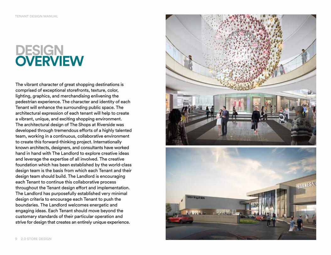
The vibrant character of great shopping destinations is comprised of exceptional storefronts, texture, color, lighting, graphics, and merchandising enlivening the pedestrian experience. The character and identity of each Tenant will enhance the surrounding public space. The architectural expression of each tenant will help to create a vibrant, unique, and exciting shopping environment. The architectural design of The Shops at Riverside was developed through tremendous efforts of a highly talented team, working in a continuous, collaborative environment to create this forward-thinking project. Internationally known architects, designers, and consultants have worked hand in hand with The Landlord to explore creative ideas and leverage the expertise of all involved. The creative foundation which has been established by the world-class design team is the basis from which each Tenant and their design team should build. The Landlord is encouraging each Tenant to continue this collaborative process throughout the Tenant design effort and implementation. The Landlord has purposefully established very minimal design criteria to encourage each Tenant to push the boundaries. The Landlord welcomes energetic and engaging ideas. Each Tenant should move beyond the customary standards of their particular operation and strive for design that creates an entirely unique experience.
DESIGNOVERVIEW
9 2.0 STORE DESIGN
TENANT DESIGN MANUAL

Tenant design professionals are encouraged to view these renderings as inspiration to create storefronts that enhance the shopping experience at The Shops at Riverside. Tenants are encouraged to exceed and not simply replicate mall prototype storefronts. High-quality materials, trendsetting design and balanced composition shall be a high priority of the Tenant design professional and will be carefully reviewed, encouraged, and enforcedby the Tenant Coordinator.
TENANT DESIGN EXPRESSION
10 2.0 STORE DESIGN
TENANT DESIGN MANUAL

TENANT DESIGN MANUAL
11 2.0 STORE DESIGN
The general design philosophy is to conceive newstores and new storefronts with maximum height and transparency using a refreshingly new design approach, resulting in innovative, state-of-the-art storefront and signage design. Tenants are encouraged to express their individuality and their brand identity through their originality in store design and merchandising.
This Tenant Design Manual is intended to work in conjunction with The Architectural Criteria Book and MEP Criteria Drawings. Please refer to the Tenant Design Manual for important property-specific details and design information. In the event of a discrepancy between this criteria, mall criteria, lease, and lease exhibits, the most stringent shall take precedence. Tenant, Tenant’s design professional, and/or Tenant’s general contractor shall confirm the criteria in question with the Tenant Coordinator before execution of work (or such work shall be corrected by Tenant at Tenant’s expense). All components of the Tenant Information Package can be found at www.simon.com, Leasing/ Property Name/Property Information.
GENERAL DESIGN CRITERIA STOREFRONT DESIGN CONTROL ZONE
The Tenant Storefront Design Control Zone is the area of the store extending from the storefront lease line into the store a minimum of five feet (5’-0”) across the entire width of the store. Since the appearance of this zone is critical to the overall store appearance, design solutions, and materials are expected to be of the highest quality.The design zone will be closely reviewed by Landlord for design and use.
Ceiling materials shall consist of gypsum board, wood, metal, or other types of hard surface materials. Acoustical ceilings and open ceilings will not be permitted in this zone.
Sprinkler heads shall be fully recessed with cover plates at entry vestibule and storefront show windows.
Any speakers within 5’-0” of the entry shall have a separate volume control that can be set to the Mall Manager’s specified level.

TENANT DESIGN MANUAL
STOREFRONT DESIGN CONTROL ZONE
The backs of Emergency Exit signage/lights (over the entry doors) must not be visible from the common area.
Security systems shall be fully concealed. Gate style or stanchion security systems are not permitted if visible from the exterior common area. Security cameras, vision panels, or “bubbles” shall not be exposed to public view in the Design Control Zone.
All walls within this zone shall be provided with high-quality finish material—plain painted surfaces are not permitted. Materials such as stone, tile, wood panels, the use of trim, and other decorative treatments shall be utilized. Slat wall and grid wall are not permitted.
No previous Tenant storefront, or storefront materials, fixtures, or finishes shall be reused.
12 2.0 STORE DESIGN
Extending 5’-0” back from the storefront glazing, the side walls and show windows shall be dedicated for use as a high-quality show window display. A creative display is required for standard merchandise racks, and wall finishing materials such as slat wall and prepackaged wall mounted grid systems are prohibited.
Distinctive, high-quality, and appropriate display techniques, which best showcase the Tenant’s merchandise, must be used.
At the storefront entry, display fixtures and merchandise must be placed at least 3’-0” behind the Tenant’s entry door. Merchandise rack and display features must not block customer traffic flow in and out of the store.
STORE DISPLAY & MERCHANDISING
LOW CEILINGS OR SOFFITS WITHIN THE CONTROL ZONE
There are occurrences within some of the Tenant spaces in which there is a drop-in ceiling height within the Tenant Design Control Zone. In this case, Tenants are encouraged to minimize this transition as much as possible. The use of similar or same ceiling or Control Zone materials is recommended and anything that would bring attention to this condition such as color or lighting is discouraged.
ENTRIES & WINDOWS
Doorways are celebrated and made monumental by a series of special elements added to the frame around the wall. All window and door openings shall be square or vertical in proportion, and any other divisions of openings shall happen as a system of squares or vertically proportioned rectangles.
TENANT DESIGN MANUAL
13 2.0 STORE DESIGN
TRANSPARENCY
Retail ground floors shall have between 60% and 80% glazing, as measured from the finished floor. Colored or mirrored glazing and glass block are inappropriate.
ACOUSTICS AND SOUND CONTROLProper sound control will be required for all Tenants, including retail and restaurant. Additional information on sound and noise control for all Tenants is on page 21.
Display window lighting shall be LED or similar light source, as approved by the Landlord. Light sources and track lighting must not be visible from the common area. Sodium lamps are prohibited in storefront areas.
Show windows and display areas should be adequately lighted and ventilated. Exposed fixture lamps are prohibited without prior Landlord approval. No lamp shall extend below the ceiling or below the display window heads in the Design Control Zone. Displays, show windows and entrances shall be illuminated during Shopping Center’s hours of operation, and shall be controlled by an automatic time-clock or control system connected to the Tenant’s power supply.
All emergency and exit lighting for the Tenant premises shall be by the Tenant and shall be provided with emergency battery power backup.
The Tenant is prohibited from providing any sign, light, or other building feature, extension, or attachment that will interfere with the Landlord’s common area lighting. Strobe, spinner, chase, or moving type of lighting will not be allowed.
STOREFRONT LIGHTING

TENANT DESIGN MANUAL
14 2.0 STORE DESIGN
L.E.D. SCREENS
L.E.D. screens proposed to be installed at the storefront or within the Design Control Zone require approval by the Landlord, and will be reviewed on a case-by-case basis. If approved, L.E.D. screens shall be incorporated into the overall storefront design and are to be encased within attractive display fixtures to conceal all surfaces except for the screen surface.
They must be mounted a minimum of 3’-0” behind the storefront glass and must incorporate slow-fade-type graphics with no sound, animation, fast movement, strobing, or flashing. Maximum screen size is 42” measured diagonally. All cables and wiring must beconcealed from view.
Approved LED samples

TENANT DESIGN MANUAL
STOREFRONT DESIGN EXAMPLES
7Renderings & images for illustrative purposes only. Dimensions and conditions noted on this rendering may vary and must be veri� ed on the Base Building drawings.
TYPE A, B, & C STOREFRONT EXAMPLES
OPEN GLAZED EXPOSURE
CLASSIC PORTAL
GRAPHIC FACADE

TENANT DESIGN MANUAL
STOREFRONT DESIGN EXAMPLES
10Renderings & images for illustrative purposes only. Dimensions and conditions noted on this rendering may vary and must be veri� ed on the Base Building drawings.
TYPE D, E, F, G & H STOREFRONT EXAMPLES
QUALITY FINISHES
ILLUMINATED PANELS
OPEN STOREFRONT

TENANT DESIGN MANUAL
17 2.0 STORE DESIGN
Tenant’s storefront design shall maximize the use of glazing and will be subject to Landlord approval. Full height opaque areas of the storefront shall be minimal. A constant height opaque sign band, that extends flat across the entire storefront width, is not acceptable. Varied glazed show window heights and/or projections should be incorporated.
All storefront glazing shall be tempered. Butt joint glazing gaps shall not exceed 3/8”. Glazing clips shall be utilized for stability per manufacturers/structural recommendations. Silicone joints are not permitted.
All storefront materials shall be high-quality, durable finishes with minimal maintenance requirements.
NOTE: Artificial finishes, faux products, or synthetic stone, brick, wood, etc. will be carefully reviewed for application, durability, and authenticity.
Storefront and glazing graphics, film, and projection techniques shall be clearly shown on Tenant’s drawings and are subject to Landlord’s approval.
STOREFRONT MATERIALS
ACCEPTABLE — Brick, Stone, Marble, Granite, Hardwood, Wood Veneer
(commercial grade products for use in high-traffic areas)— Powder-Coated Metal or High-Tech Finishes— Glazing (tempered)— Precast/GFRC/GFRG
UNACCEPTABLE — Plastic Laminates/Metal Laminates/Plastic Panels— Painted Drywall (below 8’-0” AFF)— Slat Wall or Pegboard, Mill Finish— Aluminum Storefront/Curtain Wall Systems— Metal Finishes, Anodized Aluminum, Mirror Finishes— Field-Painted Metals— Plexiglas or Plastics, Vinyl or Fabric Wall Coverings— Soft Woods or Wood Veneers (except for commercial grade
products for use in high-traffic areas)— Lay-In Tile Entrance Ceilings (entry ceilings shall be hard
surface such as drywall throughout the Design Control Zone)— Surface-Mounted Track Lighting in Entrances or Show
Windows (track shall be recessed)— Reinforced EIFS (Exterior Finish Systems) or Stucco
In general, service doors are a Tenant responsibility. Where these doors are visible from the common area, Tenant shall thoughtfully coordinate door into design of the Tenant's facade area.
SERVICE DOORS

TENANT DESIGN MANUAL
18 2.0 STORE DESIGN
STOREFRONT MATERIALS

TENANT DESIGN MANUAL
When allowed in the lease, tenants who are permitted to have outdoor patios may design and install a perimeter fence or enclosure, subject to Landlord approval. Rails and enclosures shall be self-supporting (not attached to Landlord’s facade) and shall be integrated with the Tenant’s exterior expression.
Rails and enclosures shall meet all applicable requirements of the local jurisdiction. All concrete fasteners must be concealed and alteration of Landlord’s concrete sidewalk is not permitted.
Overhead structures must also display a design consistent with a high-end center and compliment the aesthetic of the overall facade exterior and when used, design of overhead structure must be fully integrated with the rail system. Transparency through the Tenant’s enclosure is important - a solid full height railing system is not permitted.
ACCEPTABLE — Glass Panels— Stainless Steel Posts, Cables, and Rails — Wood Posts and Rails— Painted Metal Posts and Rails (fully welded
construction - no exposed fasteners)— Louvered Roof System, including vertical enclosure
walls, similar to an Arcadia louvered roof system
UNACCEPTABLE — Roll-Down Canvas and Plastic Enclosures for the
Vertical Enclosure— Signage on Rails or Enclosures— Temporary Structures— Canvas
PATIO RAILS & OVERHEAD ENCLOSURES
RETAIL TEN
AN
T DESIG
N C
RITERIATH
E SHO
PS AT C
LEARFO
RK
20IN PROGRESS
Renderings & images for illustrative purposes only
2.0 Store Design
When allowed in the lease, tenants who are permitted to have outdoor patios may design and install a perimeter fence or enclosure, subject to Landlord approval. Rails and enclosures shall be self supporting (not attached to Landlord’s facade) and shall be integrated with the tenant’s exterior expression.
Rails and enclosures shall meet all applicable requirements of the local jurisdiction and supports must be surface mounted to the Landlord’s concrete sidewalk within the zone identified on the TSD for rails and overhead structures and shall not utilize a cantilever support the columns along the continuous footing (the rail and overhead support zone) shall be limited to 10’-0” o.c. maximum which is about 75 S/F of tributary area of canopy for each column. All concrete fasteners must be concealed and alteration of Landlord’s concrete sidewalk is not permitted. Horizontal rail picket design is preferred but a vertical picket design will be considered provided that it is of a high design caliber.
Overhead structures must also display a design consistent with a high end center and compliment the aesthetic of the overall facade exterior and when used, design of overhead structure must be fully integrated with the rail system. Transparency through the Tenant’s enclosure is important - a solid full height railing system is not permitted.
PATIO RAILS & OVERHEAD ENCLOSURES ACCEPTABLE MATERIALS
• Glass panels
• Stainless steel posts, cables and rails
• Wood posts and rails
• Painted metal posts and rails (fully welded construction - no exposed fasteners)
• Canvas for overhead canopy only - provided that the profile, massing and detailing are of a high caliber of design
• Louvered roof system, including vertical enclosure walls, similar to an arcadia louvered roof system
UNACCEPTABLE MATERIALS
• Wrought iron
• Roll down canvas and plastic enclosures for the vertical enclosure
• Signage on rails or enclosures
• Temporary structures

TENANT DESIGN MANUAL
20 2.0 STORE DESIGN
Furniture for outdoor dining should be built for outdoor use and should be sufficiently sturdy to withstand reasonable variations of weather and wind. Both chairs and tables should be compact to allow the greatest flexibility in seating options.
PATIO FURNITURE
ACCEPTABLE — Chairs of metal (aluminum, steel, or wrought iron), wood,
natural materials (wicker or rattan), or metal frames with natural, wood, or plastic parts (resin-woven wicker). All chairs must match. Colors should be natural or dark colors.
— Tables of natural materials (wicker, rattan), metal (aluminum, steel, or wrought iron), with metal, stone, wood, or resin tops. Tables should be natural or dark colors. Although more than one size and shape of table can be used, all tables should match in style.
— Umbrellas made of outdoor fabric with metal stands. Umbrellas should be compact in size and square is preferred over round. Plain colors rather than stripes are preferred. All parts of any umbrella (including the fabric and supporting ribs) must be contained entirely within the outdoor seating area. When extended, the umbrella must measure at least 7’ above the surface of the outdoor dining area in order to provide adequate circulation space below. Any part of the umbrella may not exceed 10’ above the level of the sidewalk. No plastic fabrics, plastic/vinyl-laminated fabrics are permitted.
— All outdoor lighting, if provided, must be approved by Landlord.
UNACCEPTABLE — Any furniture or accessories other than chairs and tables (no
warming tables, bus tables, etc.)
RETAIL TEN
AN
T DESIG
N C
RITERIATH
E SHO
PS AT C
LEARFO
RK
20IN PROGRESS
Renderings & images for illustrative purposes only
2.0 Store Design
When allowed in the lease, tenants who are permitted to have outdoor patios may design and install a perimeter fence or enclosure, subject to Landlord approval. Rails and enclosures shall be self supporting (not attached to Landlord’s facade) and shall be integrated with the tenant’s exterior expression.
Rails and enclosures shall meet all applicable requirements of the local jurisdiction and supports must be surface mounted to the Landlord’s concrete sidewalk within the zone identified on the TSD for rails and overhead structures and shall not utilize a cantilever support the columns along the continuous footing (the rail and overhead support zone) shall be limited to 10’-0” o.c. maximum which is about 75 S/F of tributary area of canopy for each column. All concrete fasteners must be concealed and alteration of Landlord’s concrete sidewalk is not permitted. Horizontal rail picket design is preferred but a vertical picket design will be considered provided that it is of a high design caliber.
Overhead structures must also display a design consistent with a high end center and compliment the aesthetic of the overall facade exterior and when used, design of overhead structure must be fully integrated with the rail system. Transparency through the Tenant’s enclosure is important - a solid full height railing system is not permitted.
PATIO RAILS & OVERHEAD ENCLOSURES ACCEPTABLE MATERIALS
• Glass panels
• Stainless steel posts, cables and rails
• Wood posts and rails
• Painted metal posts and rails (fully welded construction - no exposed fasteners)
• Canvas for overhead canopy only - provided that the profile, massing and detailing are of a high caliber of design
• Louvered roof system, including vertical enclosure walls, similar to an arcadia louvered roof system
UNACCEPTABLE MATERIALS
• Wrought iron
• Roll down canvas and plastic enclosures for the vertical enclosure
• Signage on rails or enclosures
• Temporary structures

TENANT DESIGN MANUAL
Food Service Tenants may install natural gas heaters, and ceiling fans that are rated for outdoor use, are permanently installed, and are designed to be fully integrated into the character of the Tenant’s exterior presentation. No items may be supported from Landlord’s walls, all conduit and piping must be concealed from public view, and mobile propane heating units are not allowed. Exterior fire features may be proposed and are subject to the requirements of this section and Landlord’s approval.
HEATING ELEMENTS
Tenants are encouraged to select outdoor furnishings that enhance the guest experience of their facility and complement the overall look of the center. Pieces must be commercially rated, comply with all local jurisdictional requirements, and are subject to Landlord’s approval. All pieces must be located within the Tenant’s patio area described in the lease documents. Planters are not permitted to drain onto or stain hardscape.
OUTDOOR FURNISHINGS & PLANTERS
Tenants that are permitted patios are encouraged to design their patios to allow the inside of the restaurant to open out onto the patio by using Nanastyle sliding, bi-fold, or overhead garage-style doors or overhead structures.
RESTAURANT MUSIC AND LOUDSPEAKER MANAGEMENT
Tenants with outdoor seating wishing to provide music must provide accessible volume controls that can be managed by the Tenant's reception desk and sound levels will be coordinated with Property Management requirements. Notification of seating should be electronically through hand-held devices or text.
Tenants should not hang speakers on concrete columns or building components that can cause reverberation in adjoining spaces or above. If this is unavoidable then the speakers will need vibration isolation with transmission not to exceed 1% at a driving frequency of 30 Hz.
Tenants will be required to add specialty gypsum board (ASTM C 1396/C 1396M) and/or sound attenuation blankets (ASTM C 665) along with acoustical sound sealants and/or acoustical sound baffling panels or materials in or on and above their demising walls if they play music or have internal loudspeakers. Retail to restaurant STC should be rated at STC 65. Maximum interior sound decibels should be no more than 85 dBA.
INDOOR/OUTDOOR EXPERIENCE
21 2.0 STORE DESIGN
TENANT DESIGN MANUAL
22 2.0 STORE DESIGN
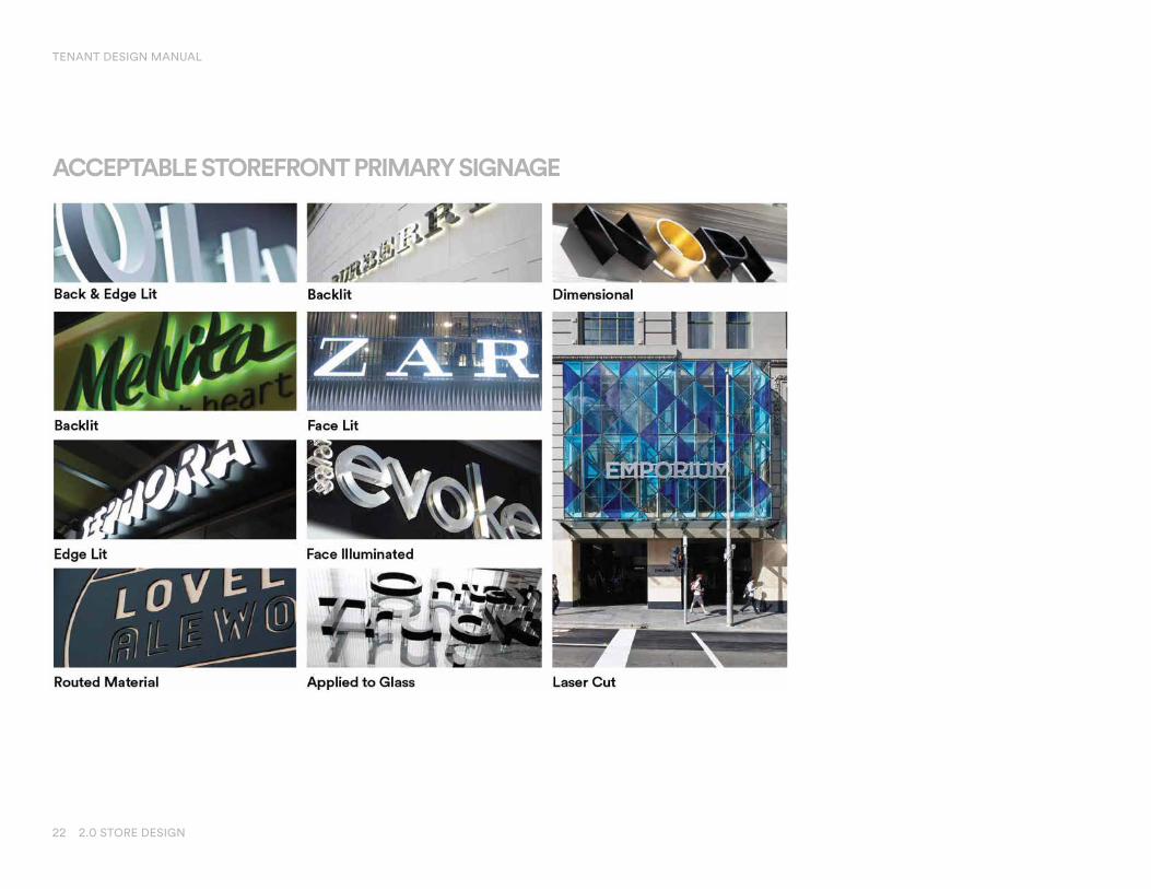
ACCEPTABLE STOREFRONT PRIMARY SIGNAGE

TENANT DESIGN MANUAL
23 2.0 STORE DESIGN
ACCEPTABLE SECONDARY SIGNAGE/GRAPHIC
30Renderings & images for illustrative purposes only. Dimensions and conditions noted on this rendering may vary and must be veri� ed on the Base Building drawings.
ACCEPTABLE SECONDARY SIGNAGE/GRAPHIC
Vinyl Graphic
Graphic Pattern
Brand Graphic
Floor Sign
Graphic Pattern
Brand Graphic

TENANT DESIGN MANUAL
24 2.0 STORE DESIGN
All interior signs that are within 5’-0” of the Tenant storefront lease line shall be specifically approved in writing by the Landlord.
All signage is to be of the highest quality design and construction. Tenant signage shall be designed to be proportionate in scale to the elevation to which it is affixed. Use of the national corporate logos and/or insignia is encouraged. All attachments, labels, fasteners, mounting brackets, wiring, clips, transformers, disconnects, lamps (except exposed neon tubes), and other mechanisms required for all signage shall be concealed from view. Light leaks are not permitted. Weep holes are permitted only on exterior signs.
Illuminated signs must be connected to a 7-day, 24-hour time clock set to the hours specified by the Mall Management.
GENERAL SIGNAGE CRITERIA
The following types of signs and sign components are a sample of signs that are permitted:
— Internally illuminated individual channel letters with opaque metal sides and acrylic plastic face, illuminated within by 3700-K-3500-K neon or LED lighting systems.
— Metal letters backlit to produce a “halo” effect, illuminated with 3700-K-3500-K neon or LED lighting systems.
— Light boxes may be permitted if recessed and integrated into the overall design of the storefront. Exposed lighted surfaces are limited to the letters. The background shall be opaque, and of high-quality natural materials (i.e. brushed metal, opaque glass, etc.).
— Edge-lit, sandblasted glass.
— Gold leaf or silk screened on front of backlit tempered glazing.
— All letters shall be of fully welded construction.
— All electrical signage shall bear the UL label and must comply with all governing codes.
— All conduit, raceways, crossovers, wiring, ballast boxes, transformers, and other equipment necessary for sign connection shall be concealed.
— Channeled letters, belts, fastenings, and clips shall be of enameling iron with porcelain enamel finish; stainless steel, polished brass or copper, or carbon baring steel with painted finish. No black iron material will be allowed.

TENANT DESIGN MANUAL
25 2.0 STORE DESIGN
The following types of signs and sign components are strictly prohibited:
— Taglines (regardless of DBA) and signs advertising products, services, or vendors.
— Box or cabinet-type construction where the outline of the box or cabinet is visible (the box or cabinet must be fully embedded into the storefront framing and finish).
— Signs employing audible equipment, and/or moving, flashing, or blinking lights.
— Signs employing exposed raceways, ballast boxes, or transformers.
— Sign manufacturers’ names, stamps, or decal.
— Signs employing luminous vacuum-formed-type plastic letter signs.
— Signs employing unedged or uncapped plastic letters with no returns and exposed fastenings.
— Paper or cardboard signs, stickers, or decals hung around, on, or behind storefront.
— Exposed tube neon signs (except for open face channel letters).
— Freestanding, moving, rotating, flashing, noise making, or odor producing signs.
— Signs which are not professional in appearance.
— Blade signs.
GENERAL SIGNAGE CRITERIA

TENANT DESIGN MANUAL
26 2.0 STORE DESIGN
Tenant shall provide and install a storefront identification sign for the premises. Each individual Tenant’s storefront identification sign shall be installed on the Tenant’s storefront surface and shall be integrated into the overall storefront design.
Storefront identification signage shall not be located closer than two feet six inches (2’-6”) from the edge of each neutral pier or side lease line.
One primary sign per store elevation to comply with all local codes. Sign size, proportion, and placement to be designed to integrate into facade.
STOREFRONT PRIMARY SIGNAGE
REAR SERVICE DOOR SIGNAGE
The Landlord has established a standard design for service door signage, naming the Tenant and suite number. No additional signage shall be permitted unless approved by the Landlord.

TENANT DESIGN MANUAL
27 2.0 STORE DESIGN
— If a construction barricade does not exist in front of the Tenant space, the Tenant is required to install a 5/8” plywood board enclosure. The barricade may be placed 3 feet in front of the Lease Line as long as a ten-foot minimum clearance is maintained between the barricade and the nearest obstruction.
— It is the Tenant contractor’s responsibility to ensure barricade placement meets egress, life safety, and building code requirements.
— Barricades should be finish painted 5/8” plywood with 2x4 metal studs at 16” on center. A 6 mil. clear plastic cover is to be installed over the top of the barricade to prevent dust transmission. A 3’-0” x 6’-8” hollow core access door with an “in” swing is permitted only when the premises do not have a rear service entrance.
— Barricades should be braced to maintain stability. Bracing should be made to Tenant materials inside the Lease Line. Do not attach any framing to Landlord finishes. Precautions should be taken to protect Landlord finishes.
— 3M full-color, peel-and-stick graphics are required and must cover the entire surface of the enclosure. Prior to printing and installation, the Tenant shall submit full-color graphic content to the Landlord for approval. Contractor signs are not permitted.
— Temporary barricade graphics offer the Tenant an opportunity to showcase their brand.
TEMPORARY BARRICADE

5.0 MEP & HVAC PLANS 28
RETAIL TENANT DESIGN CRITERIA
3.0 BUILDINGCONDITIONS

29 3.0 BUILDING CONDITIONS
THE FOUNTAIN SPA
WOMEN'S RESTROOM
SECURITY
VAULT
VAULT
STORAGE
VALVE #5
MR
LEVEL ONE
ABOVE
LEVEL ONE
ABOVE
ELEC #2BLUEPRINT
MR
L.A. 1MAINT
EMR
VEST
LOADING
L.A. #2
TRUCKCOURT
TRUCKCOURT
TRUCKCOURT
TRUCKCOURT
LOBBY
MEN'S RESTROOM
STOR
DECK ONE
ABOVE
CRAWL SPACE ELEC #5
SHOP
EMR
VALVE RM #2
SECSTOR
POTTERYBARN
ELEVATOR
MORTON'SELEVATOR
EMRSTORAGE
DAS
TRUCK DOCK
SPRINKLER
ELEC
LOBBY
CONFERENCECENTER
MANAGEMENTOFFICE
EMR
MR
FAMRR
STORAGE
STORAGE
ST
ST
WATER FEATURE
ELEC
PUMP ROOM
CRAWLSPACE
EMR
CRAWL SPACE
ST
015
4 5 6 7 8 9 10 11 12 13 1 18 20 23 27 28 29 30 31 32
1V
U
T
S
R
Q
P
M
K
J
G
1V
U
T
S
R
Q
N
L
H
F
4 4.1 5.1 6.1 7.9 8.48.1 9.1
27 28 29 30 31 32
5
LUXE
OPE
N
OPEN
OPEN
OPEN
OPE
N
OPEN
ELEC #7ELEC #6
STOR
VEST
OPE
N
VEST
ROOF
JAN
VEST
STOR
OPEN
JAN
MORTON'SELEVATOR
POTTERYBARN
ELEVATOR
OPEN
OP
EN
OPEN OPEN OPEN OPENOPEN
BALCONY
MEN'S RESTROOM
WOMEN'S RESTROOMJ
FAMRR
OPEN
BALCONY
OP
EN
TO
BE
LOW
OP
EN
TO
BE
LOW
OPEN
OPEN TORESTAURANT
BELOW
ELEC
ATM
MORTON'SELEVATOR
ELEC
VEST
NUSR
313
086
209
231
237A 245A 253 259
274
272262256250244A240
212
310 201306
200
225
4 5 6 7 8 9 10 11 12 13 15 18 20 23
U
T
S
R
P.8
P
M
K
J
V
U
T
S
R
Q
N
L
H
F
E
D
C
B
A
16 17 19 21 24 26 27 28 29 30 31 32
G.3
1211
1098.1
OPEN
OPEN
ELEC #5
JAN
STOR
EMR
MEN'S RESTROOM
WOMEN'S RESTROOM
VEST
VEST
VEST
VEST
VESTIBULE
ELEC #8 ELEC #9
JAN
VEST
R
OPEN
OPEN
JAN
MORTON'SELEVATOR
POTTERYBARN
ELEVATOR
NURRM
J
ME
N'S
RR
WO
MEN
'SRR
FAMRR
OPEN
EQVEST
E
MORTON'SELEVATOR
050
060
070
084A
090 092 094
098
101
105
147
149A
169
171
175
181
168
113
086
155
123A 123AB
109A
129A 131
136A128B122114
110
106
127A
194C 193
180A
146B
146A
192A
182A
140A
183
135 137 143B143A
194D
150
186
100191B
274
185
188A
173B
173A
4 5 6 7 8 9 10 11 12 13 15 18 20 23
U
T
S
R
Q
P
M
K
J
U
T
S
R
Q
N
L
H
F
E
D
C
B
A
14 16 19 21 22 24 26 27 28 29 30 31 3217
2 3 4 5 6 7
D
E
1.5
G
7.8
C
B
1211
1098.1
PROJECT:
DESCRIPTION:
DRAWING FILE NAME:
DRAWING:
SCALE:
DATE LAST MODIFIED:
COMPANION DRAWING:
WORK ORDER #:
CORP. #
DRAWN BY:
LOCATION:
Other revision information could be available - See CAD Department for details
REVISION HISTORY:
225 W. Washington StreetIndianapolis, IN 46204
(317) 636-1600
THE SHOPSAT RIVERSIDEHACKENSACKNEW JERSEY
FLOORPLANS
355473 \DP\41-2
ERWOOD January 04, 2018
DP41-1
5257
50250
First Level
Second Level
Basement LevelEX TDM FLOOR PLANS
configuration and occupants of the Center at any time.exhibit will at any time be occupants of the Center. Landlord reserves the right to modify size,stores will be as illustrated on this exhibit, or that any tenants which may be referenced on thisrepresentation or agreement by Landlord that the Center, Common Areas, buildings and/orThis exhibit is provided for illustrative purposes only, and shall not be deemed to be a warranty,
OVERALL CENTER PLAN
TENANT DESIGN MANUAL
FIRST LEVEL
30 3.0 BUILDING CONDITIONS
THE FOUNTAIN SPA
WOMEN'S RESTROOM
SECURITY
VAULT
VAULT
STORAGE
VALVE #5
MR
LEVEL ONE
ABOVE
LEVEL ONE
ABOVE
ELEC #2BLUEPRINT
MR
L.A. 1MAINT
EMR
VEST
LOADING
L.A. #2
TRUCKCOURT
TRUCKCOURT
TRUCKCOURT
TRUCKCOURT
LOBBY
MEN'S RESTROOM
STOR
DECK ONE
ABOVE
CRAWL SPACE ELEC #5
SHOP
EMR
VALVE RM #2
SECSTOR
POTTERYBARN
ELEVATOR
MORTON'SELEVATOR
EMRSTORAGE
DAS
TRUCK DOCK
SPRINKLER
ELEC
LOBBY
CONFERENCECENTER
MANAGEMENTOFFICE
EMR
MR
FAMRR
STORAGE
STORAGE
ST
ST
WATER FEATURE
ELEC
PUMP ROOM
CRAWLSPACE
EMR
CRAWL SPACE
ST
015
4 5 6 7 8 9 10 11 12 13 1 18 20 23 27 28 29 30 31 32
1V
U
T
S
R
Q
P
M
K
J
G
1V
U
T
S
R
Q
N
L
H
F
4 4.1 5.1 6.1 7.9 8.48.1 9.1
27 28 29 30 31 32
5
LUXE
OPE
N
OPEN
OPEN
OPEN
OPE
N
OPEN
ELEC #7ELEC #6
STOR
VEST
OPE
N
VEST
ROOF
JAN
VEST
STOR
OPEN
JAN
MORTON'SELEVATOR
POTTERYBARN
ELEVATOR
OPEN
OP
EN
OPEN OPEN OPEN OPENOPEN
BALCONY
MEN'S RESTROOM
WOMEN'S RESTROOMJ
FAMRR
OPEN
BALCONY
OP
EN
TO
BE
LOW
OP
EN
TO
BE
LOW
OPEN
OPEN TORESTAURANT
BELOW
ELEC
ATM
MORTON'SELEVATOR
ELEC
VEST
NUSR
313
086
209
231
237A 245A 253 259
274
272262256250244A240
212
310 201306
200
225
4 5 6 7 8 9 10 11 12 13 15 18 20 23
U
T
S
R
P.8
P
M
K
J
V
U
T
S
R
Q
N
L
H
F
E
D
C
B
A
16 17 19 21 24 26 27 28 29 30 31 32
G.3
1211
1098.1
OPEN
OPEN
ELEC #5
JAN
STOR
EMR
MEN'S RESTROOM
WOMEN'S RESTROOM
VEST
VEST
VEST
VEST
VESTIBULE
ELEC #8 ELEC #9
JAN
VEST
R
OPEN
OPEN
JAN
MORTON'SELEVATOR
POTTERYBARN
ELEVATOR
NURRM
J
ME
N'S
RR
WO
MEN
'SRR
FAMRR
OPEN
EQVEST
E
MORTON'SELEVATOR
050
060
070
084A
090 092 094
098
101
105
147
149A
169
171
175
181
168
113
086
155
123A 123AB
109A
129A 131
136A128B122114
110
106
127A
194C 193
180A
146B
146A
192A
182A
140A
183
135 137 143B143A
194D
150
186
100191B
274
185
188A
173B
173A
4 5 6 7 8 9 10 11 12 13 15 18 20 23
U
T
S
R
Q
P
M
K
J
U
T
S
R
Q
N
L
H
F
E
D
C
B
A
14 16 19 21 22 24 26 27 28 29 30 31 3217
2 3 4 5 6 7
D
E
1.5
G
7.8
C
B
1211
1098.1
PROJECT:
DESCRIPTION:
DRAWING FILE NAME:
DRAWING:
SCALE:
DATE LAST MODIFIED:
COMPANION DRAWING:
WORK ORDER #:
CORP. #
DRAWN BY:
LOCATION:
Other revision information could be available - See CAD Department for details
REVISION HISTORY:
225 W. Washington StreetIndianapolis, IN 46204
(317) 636-1600
THE SHOPSAT RIVERSIDEHACKENSACKNEW JERSEY
FLOORPLANS
355473 \DP\41-2
ERWOOD January 04, 2018
DP41-1
5257
50250
First Level
Second Level
Basement LevelEX TDM FLOOR PLANS
configuration and occupants of the Center at any time.exhibit will at any time be occupants of the Center. Landlord reserves the right to modify size,stores will be as illustrated on this exhibit, or that any tenants which may be referenced on thisrepresentation or agreement by Landlord that the Center, Common Areas, buildings and/orThis exhibit is provided for illustrative purposes only, and shall not be deemed to be a warranty,
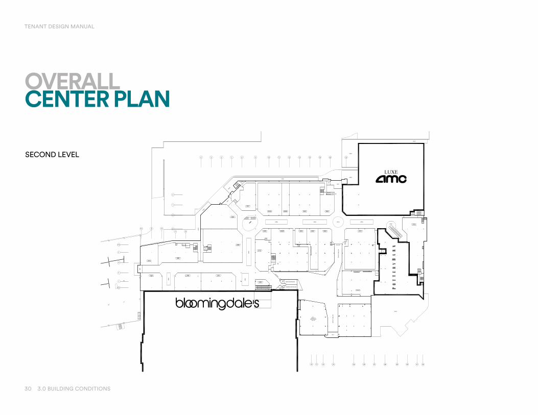
OVERALL CENTER PLAN
TENANT DESIGN MANUAL
SECOND LEVEL
31 3.0 BUILDING CONDITIONS
THE FOUNTAIN SPA
WOMEN'S RESTROOM
SECURITY
VAULT
VAULT
STORAGE
VALVE #5
MR
LEVEL ONE
ABOVE
LEVEL ONE
ABOVE
ELEC #2BLUEPRINT
MR
L.A. 1MAINT
EMR
VEST
LOADING
L.A. #2
TRUCKCOURT
TRUCKCOURT
TRUCKCOURT
TRUCKCOURT
LOBBY
MEN'S RESTROOM
STOR
DECK ONE
ABOVE
CRAWL SPACE ELEC #5
SHOP
EMR
VALVE RM #2
SECSTOR
POTTERYBARN
ELEVATOR
MORTON'SELEVATOR
EMRSTORAGE
DAS
TRUCK DOCK
SPRINKLER
ELEC
LOBBY
CONFERENCECENTER
MANAGEMENTOFFICE
EMR
MR
FAMRR
STORAGE
STORAGE
ST
ST
WATER FEATURE
ELEC
PUMP ROOM
CRAWLSPACE
EMR
CRAWL SPACE
ST
015
4 5 6 7 8 9 10 11 12 13 1 18 20 23 27 28 29 30 31 32
1V
U
T
S
R
Q
P
M
K
J
G
1V
U
T
S
R
Q
N
L
H
F
4 4.1 5.1 6.1 7.9 8.48.1 9.1
27 28 29 30 31 32
5
LUXE
OPE
N
OPEN
OPEN
OPEN
OPE
N
OPEN
ELEC #7ELEC #6
STOR
VEST
OPE
N
VEST
ROOF
JAN
VEST
STOR
OPEN
JAN
MORTON'SELEVATOR
POTTERYBARN
ELEVATOR
OPEN
OP
EN
OPEN OPEN OPEN OPENOPEN
BALCONY
MEN'S RESTROOM
WOMEN'S RESTROOMJ
FAMRR
OPEN
BALCONY
OP
EN
TO
BE
LOW
OP
EN
TO
BE
LOW
OPEN
OPEN TORESTAURANT
BELOW
ELEC
ATM
MORTON'SELEVATOR
ELEC
VEST
NUSR
313
086
209
231
237A 245A 253 259
274
272262256250244A240
212
310 201306
200
225
4 5 6 7 8 9 10 11 12 13 15 18 20 23
U
T
S
R
P.8
P
M
K
J
V
U
T
S
R
Q
N
L
H
F
E
D
C
B
A
16 17 19 21 24 26 27 28 29 30 31 32
G.3
1211
1098.1
OPEN
OPEN
ELEC #5
JAN
STOR
EMR
MEN'S RESTROOM
WOMEN'S RESTROOM
VEST
VEST
VEST
VEST
VESTIBULE
ELEC #8 ELEC #9
JAN
VEST
R
OPEN
OPEN
JAN
MORTON'SELEVATOR
POTTERYBARN
ELEVATOR
NURRM
J
ME
N'S
RR
WO
MEN
'SRR
FAMRR
OPEN
EQVEST
E
MORTON'SELEVATOR
050
060
070
084A
090 092 094
098
101
105
147
149A
169
171
175
181
168
113
086
155
123A 123AB
109A
129A 131
136A128B122114
110
106
127A
194C 193
180A
146B
146A
192A
182A
140A
183
135 137 143B143A
194D
150
186
100191B
274
185
188A
173B
173A
4 5 6 7 8 9 10 11 12 13 15 18 20 23
U
T
S
R
Q
P
M
K
J
U
T
S
R
Q
N
L
H
F
E
D
C
B
A
14 16 19 21 22 24 26 27 28 29 30 31 3217
2 3 4 5 6 7
D
E
1.5
G
7.8
C
B
1211
1098.1
PROJECT:
DESCRIPTION:
DRAWING FILE NAME:
DRAWING:
SCALE:
DATE LAST MODIFIED:
COMPANION DRAWING:
WORK ORDER #:
CORP. #
DRAWN BY:
LOCATION:
Other revision information could be available - See CAD Department for details
REVISION HISTORY:
225 W. Washington StreetIndianapolis, IN 46204
(317) 636-1600
THE SHOPSAT RIVERSIDEHACKENSACKNEW JERSEY
FLOORPLANS
355473 \DP\41-2
ERWOOD January 04, 2018
DP41-1
5257
50250
First Level
Second Level
Basement LevelEX TDM FLOOR PLANS
configuration and occupants of the Center at any time.exhibit will at any time be occupants of the Center. Landlord reserves the right to modify size,stores will be as illustrated on this exhibit, or that any tenants which may be referenced on thisrepresentation or agreement by Landlord that the Center, Common Areas, buildings and/orThis exhibit is provided for illustrative purposes only, and shall not be deemed to be a warranty,
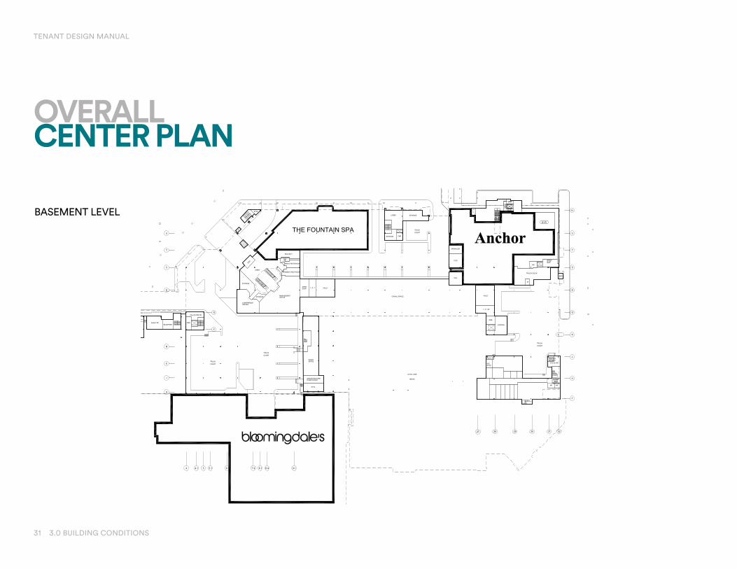
OVERALL CENTER PLAN
TENANT DESIGN MANUAL
BASEMENT LEVEL

32 3.0 BUILDING CONDITIONS
23’-8”
TENANT STOREFRONT HEIGHTSLEVEL 1
TENANT DESIGN MANUAL

33 3.0 BUILDING CONDITIONS
23’-8”
TENANT STOREFRONT HEIGHTSLEVEL 2
TENANT DESIGN MANUAL

TENANT DESIGN MANUAL
34 3.0 BUILDING CONDITIONS
LUXURY TENANT STOREFRONT HEIGHTSLEVEL 1
DN
DN
DN
TENANT180A
TENANT183
TENANT184A
TENANT192
TENANT191B
TENANT193
TENANT194
TENANT195
TENANT182A
kainc.co
m216.781.9144
Progress Date
Checked By:KA/jn:
Shee
t Des
crip
tion:
Authorized Use:
Design Development
Progress
Bidding
Building Permit
Construction
X
Des
ign
Pro
fess
iona
l,RA
#12
3456
7E
xpira
tion:
MM
/DD
/YYY
Y
gene
sis b
uild
ing
6000
lom
bard
o ce
nter
#50
0cl
evel
and,
oh
4413
1
KANJ
ARC
HITE
CTS,
PCA
NELS
ON Br
and
BASE
D ON
TEM
PLAT
E: 2
017.0
617
8/7/
2017
8:3
2:59
AM
C:\U
sers
\kco
rnet
t\Doc
umen
ts\1
7012
_Bas
e_kc
orne
tt.rv
t
THE
SHO
PS A
T R
IVER
SID
ELU
XUR
Y R
ENO
VATI
ON
(PH
ASE
III)
390
Hac
kens
ack
Ave
nue
Hac
kens
ack,
New
Jer
sey
07/AUG/17
#####
Checker
PHA
SE II
I - F
LOO
RPL
AN
SK02
REVISIONS
No. Date Description
PROJ
ECT N
ORTHPLAN
1/16" = 1'-0"SK02
1LEVEL 01 (TOC) (0'-0") Diagramatical Plan
ELEVATION A
ELEVATION B
ELEVATION C
LEGEND
TYPICALTENANT SLABLEAVEOUT

TENANT DESIGN MANUAL
35 3.0 BUILDING CONDITIONS
BO LUXE CEILING COLLAR (+29'-8")CIVIL 55.64'
LEVEL 02 (TOC)(+17'-1 1/8")CIVIL 43.06'
LEVEL 01 (TOC) (0'-0")CIVIL 25.97'
T/STOREFRONT (+23'-8")CIVIL 49.64'
B/ST
RUCT
URE
+/- 1
4'-6"
LEASE LINE
1' - 9"1' - 9"
D
SimSK03
TENANT FACADE-NO STOREFRONT VISION GLASS
BO LUXE CEILING COLLAR (+29'-8")CIVIL 55.64'
LEVEL 02 (TOC)(+17'-1 1/8")CIVIL 43.06'
LEVEL 01 (TOC) (0'-0")CIVIL 25.97'
B-5
T/STOREFRONT (+23'-8")CIVIL 49.64'
TENANT LEASE LINE
17' -
1 1/8"
6' - 6
7/8"
6' - 0
"
1' - 9"
7"
B/ST
RUCT
URE
+/-
14'-6
"
TENANT SPACECONCOURSE
BO LUXE CEILING COLLAR (+29'-8")CIVIL 55.64'
LEVEL 02 (TOC)(+17'-1 1/8")CIVIL 43.06'
LEVEL 01 (TOC) (0'-0")CIVIL 25.97'
B-6
T/STOREFRONT (+23'-8")CIVIL 49.64'
L-8
1' - 9"
TENANT LEASE LINE
VARIES
TENANT SPACECONCOURSE
BO LUXE CEILING COLLAR (+29'-8")CIVIL 55.64'
LEVEL 02 (TOC)(+17'-1 1/8")CIVIL 43.06'
LEVEL 01 (TOC) (0'-0")CIVIL 25.97'
T/STOREFRONT (+23'-8")CIVIL 49.64'
LEASE LINE1' - 9"1' - 9"
E
SimSK03
BO LUXE CEILING COLLAR (+29'-8")CIVIL 55.64'
LEVEL 02 (TOC)(+17'-1 1/8")CIVIL 43.06'
LEVEL 01 (TOC) (0'-0")CIVIL 25.97'
T/STOREFRONT (+23'-8")CIVIL 49.64'
ESK03
1' - 9" 1' - 9"LEASE LINE
kainc.co
m216.781.9144
Progress Date
Checked By:KA/jn:
Shee
t Des
crip
tion:
Authorized Use:
Design Development
Progress
Bidding
Building Permit
Construction
X
Des
ign
Pro
fess
iona
l,RA
#12
3456
7E
xpira
tion:
MM
/DD
/YYY
Y
gene
sis b
uild
ing
6000
lom
bard
o ce
nter
#50
0cl
evel
and,
oh
4413
1
KANJ
ARC
HITE
CTS,
PCA
NELS
ON Br
and
BASE
D ON
TEM
PLAT
E: 2
017.0
617
8/7/
2017
3:2
5:52
PM
C:\U
sers
\kco
rnet
t\Doc
umen
ts\1
7012
_Bas
e_kc
orne
tt.rv
t
THE
SHO
PS A
T R
IVER
SID
ELU
XUR
Y R
ENO
VATI
ON
(PH
ASE
III)
390
Hac
kens
ack
Ave
nue
Hac
kens
ack,
New
Jer
sey
07 AUG 17
#####
Checker
PHA
SE II
I - T
YPIC
AL
TEN
ANT
ELEV
ATIO
NS &
SECT
IONS
SK03
REVISIONS
No. Date Description
ELEVATIONSK03 1/4" = 1'-0"
AD60.01
ATYPICAL TENANT ELEVATION W/ 2ND FLOOR SLAB
SECTIONSK03 1/2" = 1'-0"
A10.03
DTENANT STOREFRONT @ 2ND FLOOR SLAB
SECTIONSK03 1/2" = 1'-0"
A10.03
ETENANT STOREFRONT W/O 2ND FLOOR SLAB
ELEVATIONSK03 1/4" = 1'-0"
AD60.01
BTYPICAL ELEVATION W/O 2ND FLOOR SLAB
ELEVATIONSK03 1/4" = 1'-0"
CELEVATION @ CORNER CONDITION
TENANTELEVATION

TENANT DESIGN MANUAL
36 3.0 BUILDING CONDITIONS
TENANT DETAILS DOUBLE DOORS

TENANT DESIGN MANUAL
37 3.0 BUILDING CONDITIONS
TENANT DETAILSSINGLE DOOR

TENANT DESIGN MANUAL
38 3.0 BUILDING CONDITIONS
TENANT DETAILSINTERIOR CORRIDOR DOOR

TENANT DESIGN MANUAL
39 3.0 BUILDING CONDITIONS
TENANT DETAILSCONCRETE SLAB ONFOAM DECK
(BY TENANT)

TENANT DESIGN MANUAL
40 3.0 BUILDING CONDITIONS
TENANT DETAILSDEPRESSED SLAB

TENANT DESIGN MANUAL
41 3.0 BUILDING CONDITIONS
TENANT DETAILSSTOREFRONT GRADE BEAM

TENANT DESIGN MANUAL
42 3.0 BUILDING CONDITIONS
TENANT DETAILSSLAB AT 25 ́HEIGHT STOREFRONT

43 3.0 BUILDING CONDITIONS
TENANT DETAILSTURNED DOWN SLAB
TENANT DESIGN MANUAL

4.0 ARCHITECTURAL DETAILS 44
RETAIL TENANT DESIGN CRITERIA
4.0 ARCHITECTURALDETAILS

TENANT DESIGN MANUAL
45 3.0 BUILDING CONDITIONS
DEMISING PIER TYPES LEVEL 1
Demising Pier Types (Level 1)Extra tall, wide luxury pierStone/wallcovering luxury pierLifestyle reveal pier

TENANT DESIGN MANUAL
46 3.0 BUILDING CONDITIONS
DEMISING PIER TYPES LEVEL 2
Demising Pier Types (Level 2)
Extra tall, wide luxury pier Stone/wallcovering luxury pier Lifestyle reveal pier

NEUTRAL PIERExamples of neutral pier conditions for The Shops at Riverside. Tenant should refer to the construction drawings for more information.
47 4.0 ARCHITECTURAL DETAILS
TENANT DESIGN MANUAL
i-1 •---LEASE LINE, TYPICAL
/_
�---�---TYPICAL TENANT DEMISING WALL:o/a" TYPE 'X' GYPSUM BOARD EA. SIDE OF 6"x20ga. METAL STUDS @16" O.C. TO STRUCTURE ABOVE. 6" METAL STUDS BY G.C., GYPSUM
1------....-------------,,---1 BOARD BY TENANT.
I -- - -- - --ct_ DEMISING WALL
o/a" DEEP,¾" WIDE ALUMINUM REVEAL (FRY REGLET DRM-625-75) BY TENANT
�- TENANT STOREFRONT FINISHES TO EXTEND TO EDGE OF REVEAL, TYP.
Lifestyle reveal pier

5.0 MEP & HVAC PLANS 48
RETAIL TENANT DESIGN CRITERIA
5.0 MEP & HVACDETAILS

HVAC—LEVEL 1 OF 2
TENANT DESIGN MANUAL
49 5.0 MEP & HVAC PLANS
— Equipment Packaged Split System units shall be provided and installed by the Tenant to condition the leased space. Equipment shall be sized based on Tenant’s HVAC space load calculations. – Condensing units for main mall Tenants to be
located in structurally approved locations in conjunction with Landlord’s roof plan. Tenant to be aware of the economizer mode requirements.
— Condensate Drain Tenant shall provide a condensate drain trap at the AHU drain connection above the ceiling. Tenant shall terminate to an approved waste system within the Tenant space. All condensate piping shall be copper and insulated below roof line.
— DX Pipe Routing Utilize Landlord chases to route DX piping through the roof, or to lower level for Tenants.
— Return Air Open plenum for non-odor-producing Tenants. Ducted return is subject to Landlord’s approval.
— Supply Air Design for constant volume, low velocity pressure.
— Smoke Exhaust/Relief None required.
— Odor, Thermal & Process Equipment Exhaust Odor producers (pets, hairstyling, manicures) and Food Use Tenants must maintain a minimum of 20% negative air pressure between their space and the mall. Pollution Control Unit (PCU) may be required to mitigate odors.
— Grease Exhaust Food Tenants shall provide a Grease Exhaust and Make Up Air system. Maintain negative air pressure between Tenant space and the mall. Protect roof with “Grease Guard” containment system.
— Outside/Relief Air Tenants must install intake and exhaust louvers in an adjacent exterior wall to utilize an economizer cycle. Tenants without exterior wall exposure shall connect to Landlord-provided ducts. All Tenants with roof access are thru roof by Tenant.
— Toilet Exhaust Tenants without roof access shall connect to the Landlord-provided Toilet Exhaust duct.
— Temperature Controls Tenant supplied HVAC is stand alone.
— Test & Balance Tenant shall employ a NEBB or AABC certified air system contractor to perform final testing and balancing.
— See Criteria Sheet MEP-1 for further information.

50 5.0 MEP & HVAC PLANS
HVAC—LEVEL 2 OF 2
TENANT DESIGN MANUAL
— Equipment Tenant shall furnish and install rooftop unit(s) sized per sensible/total load calculations. Heating shall be electric. All roofing by Landlord’s authorized contractor at Tenant’s expense. Air distribution within leased space is Tenant’s responsibility. Rooftop unit(s) shall be constant volume, variable temperature, self-contained and air-cooled type with air-side economizers where required by ASHRAE and AHJ.
— Condensate Drain Condensate line to drain within Tenant space (if permitted by local Code) through separate roof penetration using pipe portal. All condensate piping shall be copper and insulated below roof line. Power connection, ductwork to RTU to be within the perimeter of the roof curb.
— Return Air Open plenum for non-odor-producing Tenants. Ducted return is subject to Landlord’s approval.
— Supply Air Design for constant volume, low velocity pressure.
— Smoke Exhaust/Relief None required.
— Odor, Thermal & Process Equipment Exhaust Odor producers (pets, hairstyling, manicures) and Food Use Tenants must maintain a minimum of 20% negative air pressure between their space and the mall. Pollution Control Unit (PCU) may be required to mitigate odors.
— Grease Exhaust Food Tenants shall provide a Grease Exhaust and Make Up Air system. Maintain negative air pressure between Tenant space and the mall. Protect roof with “Grease Guard” containment system.
— Outside/Relief Air All Tenants with roof access are thru roof by Tenant.
— Toilet Exhaust By Tenant including fan, ductwork, and roof cap.
— Temperature Controls Tenant-supplied HVAC is stand alone.
— Test & Balance Tenant shall employ a NEBB or AABC certified air system contractor to perform final testing and balancing.
— See Criteria Sheet MEP-1 for further information.

51 5.0 MEP & HVAC PLANS
PLUMBING
TENANT DESIGN MANUAL
— Water Redistributed by Landlord via overhead mains. Designated connection point within or adjacent to space. Tenant-supplied meter w/remote reader.
— Waste 4˝ wye connection off Landlord main. Designated connection point within or adjacent to space.
— Vent A central sanitary vent system for Tenant use on Level 1 only for Tenant connection will be provided, otherwise, Tenant to install sanitary vent through roof by Landlord’s roofing contractor at Tenant’s expense.
— Grease Waste Landlord has provided central grease interceptor piping and designated grease interceptor locations for Tenants to install future interceptors with grease waste lines to specific in-line restaurants.
— Drinking Fountain Per code.
— Natural Gas Low pressure gas is available from the utility for Restaurants cooking use only at exterior meter bank in limited locations. Gas service is not available for Retail Tenants.
— Toilet Rooms Per code.
— Cooking Oil Management Cooking oil shall be captured in a waste oil containment tank.
— See Criteria Sheet MEP-1 for further information.

52 5.0 MEP & HVAC PLANS
FIRE PROTECTION
TENANT DESIGN MANUAL
— Implementation Tenant shall modify existing grid system in compliance with local codes and Landlord’s insurance requirements. Tenant shall directly employ the Landlord-designated contractor.
— Tenant Flow and Tamper Switch Landlord tie-in notification. Tenant’s fire alarm panel and smoke detectors must comply with mall and AHJ criteria. Tenants shall connect to the Tenant zone located in the area of their premises.
— See Criteria Sheet MEP-1 for further information.

53 5.0 MEP & HVAC PLANS
ELECTRICAL
TENANT DESIGN MANUAL
— Voltage Maximum design capacity of Tenant’s electrical system is 277/480-volt, 3-phase, 4-wire. Tenant will provide their own dry-type transformer to provide 120/208-volt, 3-phase, 4-wire for their own use as required.
— Power Tenant shall connect to the Landlord's electrical distribution system through Landlord-provided conduit and pull string. Tenant has option of providing check meter at own expense.
— Capacity Tenant maximum connection is 20 watts per square foot for Retail, 50 watts for Food Tenants. Submit connected and demand electrical load data to support electric service size requested.
— Telephone A 1” empty conduit with pull string or sleeve will be provided from the demised premises to a back of house corridor containing an IDF. J-hooks will be provided to allow the Tenant to install communication cabling, at Tenant expense. Tenant provides all tel/data wiring, hardware, and connections.
— Fire Alarm Landlord provides a connection point to each Tenant space. Tenant to utilize Landlord-approved control panel and contractor to tie in to mall's fire alarm at Tenant’s expense. Tenant's fire alarm panel and smoke detectors must comply with mall and AHJ criteria. Tenant required to install both audio & visual alarm devices per the AHJ.
— Lighting Control Tenant shall provide 24/7 time-clock control for storefront signage, storefront lighting, and storefront receptacles.
— See Criteria Sheet MEP-1 for further information.

TENANT DESIGN MANUAL
54 5.0 MEP & HVAC PLANS
Tenant’s engineer shall use their own form for HVAC Load Calculations:
— Appliance Heat Gain— Electrical Load Summary— Kitchen Exhaust Fan Specifications— Kitchen Make-Up Air Unit Specification— RTU/Split System Specification— Maintenance
MEP CALCULATION FORMS