Temporal Shape Super-Resolution by Intra-Frame Motion...
9
Temporal shape super-resolution by intra-frame motion encoding using high-fps structured light Yuki Shiba, Satoshi Ono Kagoshima University, Japan Ryo Furukawa, Shinsaku Hiura Hiroshima City University, Japan Hiroshi Kawasaki Kyushu University, Japan Abstract One of the solutions of depth imaging of moving scene is to project a static pattern on the object and use just a single image for reconstruction. However, if the motion of the object is too fast with respect to the exposure time of the image sensor, patterns on the captured image are blurred and reconstruction fails. In this paper, we impose multiple projection patterns into each single captured image to real- ize temporal super resolution of the depth image sequences. With our method, multiple patterns are projected onto the object with higher fps than possible with a camera. In this case, the observed pattern varies depending on the depth and motion of the object, so we can extract temporal infor- mation of the scene from each single image. The decoding process is realized using a learning-based approach where no geometric calibration is needed. Experiments confirm the effectiveness of our method where sequential shapes are reconstructed from a single image. Both quantitative eval- uations and comparisons with recent techniques were also conducted. 1. Introduction Active depth imaging systems for capturing dynamic scenes have been intensively investigated in response to strong demands from various fields. Previous work on dynamic scene-capture mainly used light projectors which project a static structured light pattern onto the object. Re- cently, time of flight (TOF) sensors have improved the capa- bility of real-time and high resolution capturing [13]. How- ever, from the wide variety of real-time 3D scanning sys- tems available, including commercial products, it is still a difficult task to realize high-speed 3D scans of fast-moving objects. One main reason for this difficulty comes from se- vere limitations on the light intensity of pattern projectors to sufficiently expose all the pixels of the image sensor in a short period of time. This is a common problem for all active scanning systems including both structured light and TOF sensors. Another reason is that it is still not common for imaging sensors to be capable of high speed capturing due to hardware limitations. On the other hand, based on recent progress on pre- cision devices fundamental to Digital Light Processing (DLP) technology, such as micro-electromechanical sys- tems (MEMS), extremely high fps (e.g. 10,000fps) is read- ily available. Therefore, in general, the switching speed of patterns on a projector is much faster than that of a cam- era. Based on this fact, we propose a new solution to re- construct 3D shapes of fast moving objects by projecting multiple patterns onto the object with a higher fps than that of a camera. Since it is possible to alter patterns with ex- tremely high fps, the projected pattern on a moving object is not easily blurred out and a sharp patterns are effectively preserved (Fig. 1(b)). By using these sharp patterns with our reconstruction algorithm, not only a single shape, but also sequential shapes can be recovered; we call this temporal shape super-resolution. The basic idea of a reconstruction algorithm is straight- forward; we simultaneously search the depth as well as the velocity of the object’s surface in order to best describe the captured image for each pixel by synthesizing the image us- ing an image database which is captured in advance. This is a multi-dimensional search of all pixels and the calculation time becomes enormous if brute-force search is applied. To reduce the computational time, we first obtain initial depth and velocity estimation under constant velocity assumption, then, we refine the estimation allowing varying velocities. Several experiments were conducted using an off-the- shelf DLP projector module [24] to confirm the effective- ness of our method with quantitative and qualitative eval- uation, proving that our system can recover the shape of a fast moving object with better accuracy than previous tech- niques. This paper proposed the following: 1. Multiple patterns projected into a single frame to en- code both depth and motion information, in order to recover sequential shapes of fast moving objects from a single captured image. 2. Learning-based reconstruction algorithm to avoid geo- metric calibration as well as efficient search algorithm to reduce calculation time. 3. An actual system be built with an off-the-shelf DLP projector module with an ordinary camera to realize 1,800fps reconstruction. Note that no special setup, synchronization nor extra devices are required. 115
Transcript of Temporal Shape Super-Resolution by Intra-Frame Motion...

Temporal shape super-resolution by intra-frame motion encoding
using high-fps structured light
Yuki Shiba, Satoshi Ono
Kagoshima University, Japan
Ryo Furukawa, Shinsaku Hiura
Hiroshima City University, Japan
Hiroshi Kawasaki
Kyushu University, Japan
Abstract
One of the solutions of depth imaging of moving scene
is to project a static pattern on the object and use just a
single image for reconstruction. However, if the motion of
the object is too fast with respect to the exposure time of the
image sensor, patterns on the captured image are blurred
and reconstruction fails. In this paper, we impose multiple
projection patterns into each single captured image to real-
ize temporal super resolution of the depth image sequences.
With our method, multiple patterns are projected onto the
object with higher fps than possible with a camera. In this
case, the observed pattern varies depending on the depth
and motion of the object, so we can extract temporal infor-
mation of the scene from each single image. The decoding
process is realized using a learning-based approach where
no geometric calibration is needed. Experiments confirm
the effectiveness of our method where sequential shapes are
reconstructed from a single image. Both quantitative eval-
uations and comparisons with recent techniques were also
conducted.
1. Introduction
Active depth imaging systems for capturing dynamic
scenes have been intensively investigated in response to
strong demands from various fields. Previous work on
dynamic scene-capture mainly used light projectors which
project a static structured light pattern onto the object. Re-
cently, time of flight (TOF) sensors have improved the capa-
bility of real-time and high resolution capturing [13]. How-
ever, from the wide variety of real-time 3D scanning sys-
tems available, including commercial products, it is still a
difficult task to realize high-speed 3D scans of fast-moving
objects. One main reason for this difficulty comes from se-
vere limitations on the light intensity of pattern projectors
to sufficiently expose all the pixels of the image sensor in
a short period of time. This is a common problem for all
active scanning systems including both structured light and
TOF sensors. Another reason is that it is still not common
for imaging sensors to be capable of high speed capturing
due to hardware limitations.
On the other hand, based on recent progress on pre-
cision devices fundamental to Digital Light Processing
(DLP) technology, such as micro-electromechanical sys-
tems (MEMS), extremely high fps (e.g. 10,000fps) is read-
ily available. Therefore, in general, the switching speed of
patterns on a projector is much faster than that of a cam-
era. Based on this fact, we propose a new solution to re-
construct 3D shapes of fast moving objects by projecting
multiple patterns onto the object with a higher fps than that
of a camera. Since it is possible to alter patterns with ex-
tremely high fps, the projected pattern on a moving object
is not easily blurred out and a sharp patterns are effectively
preserved (Fig. 1(b)). By using these sharp patterns with our
reconstruction algorithm, not only a single shape, but also
sequential shapes can be recovered; we call this temporal
shape super-resolution.
The basic idea of a reconstruction algorithm is straight-
forward; we simultaneously search the depth as well as the
velocity of the object’s surface in order to best describe the
captured image for each pixel by synthesizing the image us-
ing an image database which is captured in advance. This is
a multi-dimensional search of all pixels and the calculation
time becomes enormous if brute-force search is applied. To
reduce the computational time, we first obtain initial depth
and velocity estimation under constant velocity assumption,
then, we refine the estimation allowing varying velocities.
Several experiments were conducted using an off-the-
shelf DLP projector module [24] to confirm the effective-
ness of our method with quantitative and qualitative eval-
uation, proving that our system can recover the shape of a
fast moving object with better accuracy than previous tech-
niques. This paper proposed the following:
1. Multiple patterns projected into a single frame to en-
code both depth and motion information, in order to
recover sequential shapes of fast moving objects from
a single captured image.
2. Learning-based reconstruction algorithm to avoid geo-
metric calibration as well as efficient search algorithm
to reduce calculation time.
3. An actual system be built with an off-the-shelf DLP
projector module with an ordinary camera to realize
1,800fps reconstruction. Note that no special setup,
synchronization nor extra devices are required.
1115
In section 2, we explain the related work. Then, in sec-
tion 3, system configuration and overview of the algorithm
are explained followed by a detailed explanation in section
4. Finally, we evaluate the accuracy of the method followed
by limitations, and conclude the paper.
Camera’se
xposuretim
e
Projector
Object motion
Captured image
Projection pattern Observed image
Camera
Stationary
Frame 2 t
Frame 1
(a) Static pattern projection on fast moving object
Frame 1
Object motion
Captured image
Projection pattern Observed image
Projector
Camera
code 1
code 2
code 3
Frame 2 t
code 1
code 2
code 3
Camera’se
xposuretim
e
(b) Multiple pattern projection on fast moving object
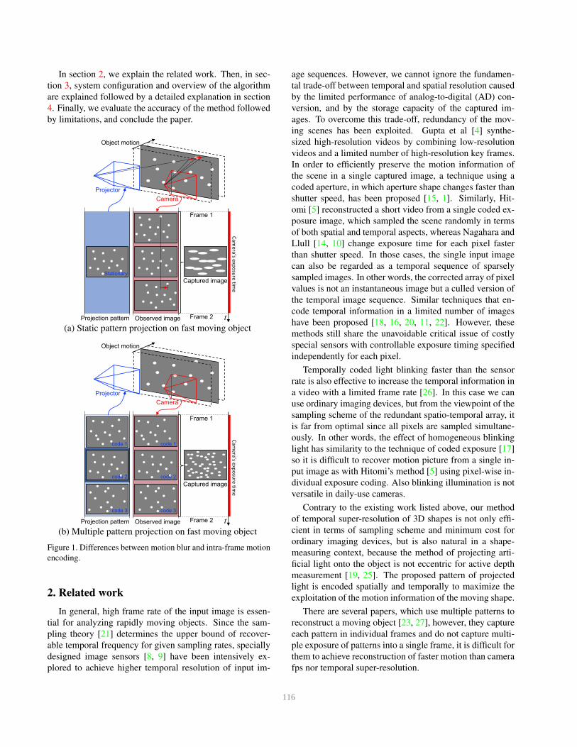
Figure 1. Differences between motion blur and intra-frame motion
encoding.
2. Related work
In general, high frame rate of the input image is essen-
tial for analyzing rapidly moving objects. Since the sam-
pling theory [21] determines the upper bound of recover-
able temporal frequency for given sampling rates, specially
designed image sensors [8, 9] have been intensively ex-
plored to achieve higher temporal resolution of input im-
age sequences. However, we cannot ignore the fundamen-
tal trade-off between temporal and spatial resolution caused
by the limited performance of analog-to-digital (AD) con-
version, and by the storage capacity of the captured im-
ages. To overcome this trade-off, redundancy of the mov-
ing scenes has been exploited. Gupta et al [4] synthe-
sized high-resolution videos by combining low-resolution
videos and a limited number of high-resolution key frames.
In order to efficiently preserve the motion information of
the scene in a single captured image, a technique using a
coded aperture, in which aperture shape changes faster than
shutter speed, has been proposed [15, 1]. Similarly, Hit-
omi [5] reconstructed a short video from a single coded ex-
posure image, which sampled the scene randomly in terms
of both spatial and temporal aspects, whereas Nagahara and
Llull [14, 10] change exposure time for each pixel faster
than shutter speed. In those cases, the single input image
can also be regarded as a temporal sequence of sparsely
sampled images. In other words, the corrected array of pixel
values is not an instantaneous image but a culled version of
the temporal image sequence. Similar techniques that en-
code temporal information in a limited number of images
have been proposed [18, 16, 20, 11, 22]. However, these
methods still share the unavoidable critical issue of costly
special sensors with controllable exposure timing specified
independently for each pixel.
Temporally coded light blinking faster than the sensor
rate is also effective to increase the temporal information in
a video with a limited frame rate [26]. In this case we can
use ordinary imaging devices, but from the viewpoint of the
sampling scheme of the redundant spatio-temporal array, it
is far from optimal since all pixels are sampled simultane-
ously. In other words, the effect of homogeneous blinking
light has similarity to the technique of coded exposure [17]
so it is difficult to recover motion picture from a single in-
put image as with Hitomi’s method [5] using pixel-wise in-
dividual exposure coding. Also blinking illumination is not
versatile in daily-use cameras.
Contrary to the existing work listed above, our method
of temporal super-resolution of 3D shapes is not only effi-
cient in terms of sampling scheme and minimum cost for
ordinary imaging devices, but is also natural in a shape-
measuring context, because the method of projecting arti-
ficial light onto the object is not eccentric for active depth
measurement [19, 25]. The proposed pattern of projected
light is encoded spatially and temporally to maximize the
exploitation of the motion information of the moving shape.
There are several papers, which use multiple patterns to
reconstruct a moving object [23, 27], however, they capture
each pattern in individual frames and do not capture multi-
ple exposure of patterns into a single frame, it is difficult for
them to achieve reconstruction of faster motion than camera
fps nor temporal super-resolution.
116
CMOS Camera
DLP projector
Close up view of
a DLP projector.
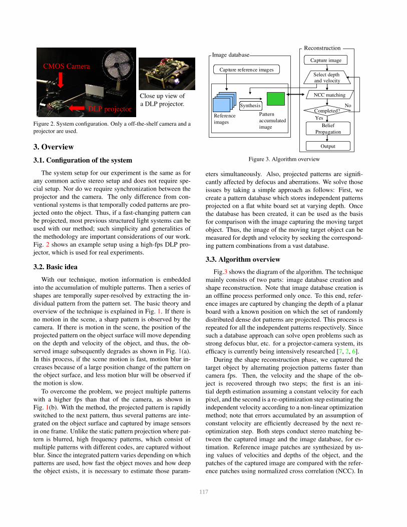
Figure 2. System configuration. Only a off-the-shelf camera and a
projector are used.
3. Overview
3.1. Configuration of the system
The system setup for our experiment is the same as for
any common active stereo setup and does not require spe-
cial setup. Nor do we require synchronization between the
projector and the camera. The only difference from con-
ventional systems is that temporally coded patterns are pro-
jected onto the object. Thus, if a fast-changing pattern can
be projected, most previous structured light systems can be
used with our method; such simplicity and generalities of
the methodology are important considerations of our work.
Fig. 2 shows an example setup using a high-fps DLP pro-
jector, which is used for real experiments.
3.2. Basic idea
With our technique, motion information is embedded
into the accumulation of multiple patterns. Then a series of
shapes are temporally super-resolved by extracting the in-
dividual pattern from the pattern set. The basic theory and
overview of the technique is explained in Fig. 1. If there is
no motion in the scene, a sharp pattern is observed by the
camera. If there is motion in the scene, the position of the
projected pattern on the object surface will move depending
on the depth and velocity of the object, and thus, the ob-
served image subsequently degrades as shown in Fig. 1(a).
In this process, if the scene motion is fast, motion blur in-
creases because of a large position change of the pattern on
the object surface, and less motion blur will be observed if
the motion is slow.
To overcome the problem, we project multiple patterns
with a higher fps than that of the camera, as shown in
Fig. 1(b). With the method, the projected pattern is rapidly
switched to the next pattern, thus several patterns are inte-
grated on the object surface and captured by image sensors
in one frame. Unlike the static pattern projection where pat-
tern is blurred, high frequency patterns, which consist of
multiple patterns with different codes, are captured without
blur. Since the integrated pattern varies depending on which
patterns are used, how fast the object moves and how deep
the object exists, it is necessary to estimate those param-
NCC matching
Image database
Reference
images
Capture reference images
Belief
Propagation
Pattern
accumulated
image
Output
Reconstruction
SynthesisSynthesis
Capture image
Select depth
and velocity
Completed?
Yes
No
Figure 3. Algorithm overview
eters simultaneously. Also, projected patterns are signifi-
cantly affected by defocus and aberrations. We solve those
issues by taking a simple approach as follows: First, we
create a pattern database which stores independent patterns
projected on a flat white board set at varying depth. Once
the database has been created, it can be used as the basis
for comparison with the image capturing the moving target
object. Thus, the image of the moving target object can be
measured for depth and velocity by seeking the correspond-
ing pattern combinations from a vast database.
3.3. Algorithm overview
Fig.3 shows the diagram of the algorithm. The technique
mainly consists of two parts: image database creation and
shape reconstruction. Note that image database creation is
an offline process performed only once. To this end, refer-
ence images are captured by changing the depth of a planar
board with a known position on which the set of randomly
distributed dense dot patterns are projected. This process is
repeated for all the independent patterns respectively. Since
such a database approach can solve open problems such as
strong defocus blur, etc. for a projector-camera system, its
efficacy is currently being intensively researched [7, 2, 6].
During the shape reconstruction phase, we captured the
target object by alternating projection patterns faster than
camera fps. Then, the velocity and the shape of the ob-
ject is recovered through two steps; the first is an ini-
tial depth estimation assuming a constant velocity for each
pixel, and the second is a re-optimization step estimating the
independent velocity according to a non-linear optimization
method; note that errors accumulated by an assumption of
constant velocity are efficiently decreased by the next re-
optimization step. Both steps conduct stereo matching be-
tween the captured image and the image database, for es-
timation. Reference image patches are synthesized by us-
ing values of velocities and depths of the object, and the
patches of the captured image are compared with the refer-
ence patches using normalized cross correlation (NCC). In
117

Code 1
Code 2
Code 3
Depth 1 Depth 2 Depth 3 Depth 4 Depth 5 Depth 6
+ + + …. =
Image patches sampled from the database Synthesized image
Constant number of samples from each patternDisparity
Figure 4. Synthesis of reference image patches for constant veloc-
ities.
our experiments, 16x16 and 24x24 pixels windows are used
for calculation. As for the pattern design, we adopted a stan-
dard dense random dot pattern used by real-time scanning
systems [12].
4. Implementation
4.1. Motion compensation database construction
In our method, learning-based approach is adopted in-
stead of geometric calibration. As mentioned in Sec.3.3, the
huge data size for learning-based approach is not just sim-
ply a weakness, but should be considered with a trade-off
between accuracy, and we take accuracy in our method.
The image database is created by capturing the actual
scene where a planar reference board on a motorized stage
is moved from dmin to dmax between the projector and the
camera. Each pattern is projected on the board and captured
each time the board is moved one predefined unit length
(0.5 mm in our experiment for sufficient accuracy in relation
to data size), thus the captured static reference images do
not involve motion blur. Because of the baseline between
the projector and the camera, the observed pattern is shifted
with disparities depending on the distance to the board. This
capturing process is repeated Npmaxtimes.
As for the projection pattern, we use multiple dense ran-
dom dot patterns to make the projected pattern as unique as
possible and to make blur clearly visible in all directions.
4.2. Initial depth and velocity estimation assumingconstant velocity
The proposed technique simultaneously estimates depth
and velocity using a multidimensional search with the ref-
erence image database. The reference images that can be
observed depends on depths and velocity. However, gen-
erating reference image patches in advance requires huge
amounts of memory and computational time for matching
Code 1
Code 2
Code 3
+ + + …. =
Image patches sampled from the database Synthesized image
Depth 1 Depth 2 Depth 3 Depth 4 Depth 5 Depth 6
Varying number of samples from each pattern
Figure 5. Synthesize of reference image patches for varying veloc-
ities.
because the combination of depth (|dmax − dmin| levels)
and velocity (vmax levels) creates enormous amounts of
data, even if constant velocity is assumed.
To reduce the computational cost, we first obtain coarse
initial solution by assuming constant velocity of the surface.
The initial solution is refined later. The velocity is changed
from −vmax to vmax and the depth is changed from dmin
to dmax. In total, 2× vmax × |dmax − dmin| the reference
image patches are generated for the captured pattern set.
In the initial estimation process, reference image patches
Iconst(v, d0) of depth at the start point d0 and constant ve-
locity v are generated by collecting image patches from the
image database and integrating them as shown in Fig. 4.
Note that, since constant velocity is assumed, the same
number of patches are sampled from each pattern code. We
calculate Iconst(v, d0) by:
Iconst(v, d0) =1
Np
TE
TrefE
Np∑
n=1
d0+n∆d∑
d=d0+(n−1)∆d
Istaticp(n+Nstart),d
∆d+ 1
(1)
where TE and TrefE are exposure time at measurement and
database construction, respectively. p(n) is n-th observed
pattern, Istaticp(n),d is static reference image of pattern p(n) at
depth d in the image database, and ∆d is the moving dis-
tance while the pattern is projected, i.e., ∆d = v TE
Np. Then,
all the generated reference images are compared to the cap-
tured image, and initial estimated values of depth and ve-
locities are computed by
d, v = argmaxd,v
NCC(
Iconst(v, d), Icap)
(2)
where Icap is a captured image.
4.3. Refinement of depth and velocity estimation
After obtaining the initial solution, the depth and ve-
locity estimation is further refined. In the refinement pro-
118

Figure 6. Captured image examples of projected pattern mark-
ers, e.g. examples 1 and 2 involve p(3), p(4), . . . , p(8) and
p(8), p(9), . . . , p(3), respectively. In example 2, p(8) is captured
with about 25% ofTE
TrefE
, respectively.
cess, nonuniform motion of the object is estimated. Veloc-
ities for each interval between the projected patterns v =(vp1
, vp2, . . . , vpNp
) are assumed to be inconstant and their
values are simultaneously estimated. Reference images for
refinement process are generated in the same way as the
coarse process with the only difference on time-variant ve-
locity as shown in Fig. 5, except that the number of samples
from each code patterns may not be constant. Then, the
reference image patch Ifine(v, d0) at initial depth d0 and
velocities v are calculated as follows:
Ifine(v, d0) =1
Np
TE
TrefE
Np∑
n=1
dn∑
d=dn−1
Istaticp(n+Nstart),d
dn − dn−1 + 1(3)
where dn =∑n
1 vpn∗ ∆t. Then, the refined depth and
velocity of each pattern are determined as follows:
d,v = argmaxd,v
NCC(
Ifine(v, d), Icap)
. (4)
To reduce the combination number of velocity values, a
constraint between velocities at adjacent intervals is im-
posed so that the difference between these values should
be less than threshold (i.e., continuous velocities).
Finally, belief propagation (BP) [3] is applied to refine
the initial shape. The cost volume obtained by NCC is used
for data terms and the absolute value of depth difference
between adjacent pixels is used for regularization terms.
4.4. Passive synchronization using markers
Although the aforementioned steps work effectively
without synchronization, the search space is vast. If the
system is synchronized, the search space can be greatly re-
duced. We propose a simple method to achieve synchro-
nization without any hardware modifications. We impose
markers corresponding to each projected pattern in the pe-
ripheral region of the projected pattern, which are not used
for measurement. The markers are captured as shown in
Fig. 6 and the intensity of each marker is calculated in order
to accurately estimate which and for how long each pattern
is captured. This allows users to use existing structured light
systems without special re-configuration.
Figure 7. Synthesized patterns with a different number of projected
patterns used. Since we assume that the object is moving, motion
blurs are observed on the synthesized images; blur is stronger in
the single pattern case than the others.
4.5. Temporal super-resolved shape reconstruction
By using the output data from the fine level, the proposed
technique produces Np shapes from a single image. Since
the shape of the first frame and a velocity of each pixel at
each frame is already estimated, a temporal super-resolved
shape at n-th pattern can be reconstructed by accumulating
∆d from 1 to n − 1 for all the pixels. To reduce accumu-
lation error, we conduct a re-optimization step with reverse
direction and average the depths from both directions.
5. Experiment
5.1. Evaluation with planar board
The first experiment was conducted by using a video pro-
jector and a CCD camera. Reference database was cap-
tured by moving the target screen by motorized stage be-
tween 500mm-800mm from the projector and the camera,
and the capturing interval was 1.0mm. Fps and a resolution
of the camera was 3Hz and 1600*1200 pixels and 30Hz and
1024*768 pixels for the video projector.
For evaluation, we attached a target board onto the mo-
torized stage, and captured it with the camera while the
board was moving under different conditions, such as with
different numbers of projected patterns, different velocity
and different material of the target object. Here, the case of
using one pattern is same as the conventional active stereo
method, therefore, to equalize the experimental conditions
between the measurement using different numbers of pat-
terns, we adjusted pattern density so that the density of the
integrated patterns becomes the same, as shown in Fig. 7.
We applied our algorithm to the captured images using
the stored database with matching window size 12*12 pix-
els. The depth value was also estimated by the commercial
device Kinect v1 [12] to show the standard ability on scan-
ning moving objects. Results are shown in Fig. 8 and 10.
119

0
0.002
0.004
0.006
0.008
0.01
0.012
0.014
0.016
1 3 6
RMSE [m]
Pattern num
Plane
Crumpled paper
Checker
Wooden board
News paper
Figure 8. Accuracy evaluation by reconstructing a planar board
with different texture using a different number of projected pat-
terns. RMSEs of reconstructed points from the fitted planes are
shown. Horizontal axis represents the number of pattern. It is
clearly shown that increased number realize better RMSE with all
the textures.
Inp
ut
Th
en
um
ber
of
use
dp
atte
rn 1
3
6
(a) (b) (c) (d)Figure 9. Example input data for the experiment of Fig. 8. (a)
crumpled paper, (b) checker pattern, (c) newspaper and (d) wood
under the condition of slow velocity in Fig. 10.
In the first graph in Fig.8, we can clearly observe that
the increase in the number of projected patterns improves
the RMSE for all textures and materials. Of all textures and
materials, checker pattern has the worst RMSE; we con-
sider that this is caused by the small size of checker pattern
used, which is a similar size to the matching window, thus
interference occurs during NCC calculation. Fig.9 shows
examples of the actual captured images. As can be seen, a
larger number of patterns result in a sharper captured image,
which in turn results in better RMSE.
In the next graph of Fig.10, we can clearly see that an in-
crease in velocity degrades the RMSE especially when the
number of the patterns is small. Since we used an ordi-
nary video projector for this experiment and the fps is just
3Hz, captured patterns are significantly blurred for a single
pattern (as shown in Fig. 11,) whereas sharp patterns are
preserved with multiple pattern projection. This results in
0.000
0.001
0.002
0.003
0.004
0.005
0.006
0.007
0.008
0.009
0.010
stoped slow normal fast
RMSE [m]
Speed
1
3
6
Kinect
Figure 10. Accuracy evaluation by reconstructing a plane board
with different velocity of target object. RMSEs of reconstructed
points from the fitted planes are shown. Horizontal axis repre-
sents the velocity of the object. It is clearly shown that accuracy
degrades when velocity become faster; typically the number of
pattern is small.
Th
en
um
ber
of
use
dp
atte
rn 1
3
6
(a) (b) (c) (d)Figure 11. Example input data for the experiment of Fig. 10. (a)
stop, (b) slow, (c) normal and (d) fast motion, respectively.
the maintenance of the lowest RMSE of all, at all velocities.
The reason why Kinect has almost constant error values at
various velocities is that the motorized stage is so slow even
at the maximum speed that no motion blur occurred with
Kinect.
5.2. Temporal super-resolution of nonuniform ve-locity
Next, super-resolved shapes were reconstructed from a
single image input. To confirm the effectiveness of the re-
finement algorithm which can estimate nonuniform veloc-
ity, we impose a constant acceleration to the target board
using the motorized stage. Reconstruction results are shown
in Fig.12 and 13. As shown in the figures, we can confirm
that the flat boards were not reconstructed at constant inter-
vals, but at squared intervals.
5.3. Arbitrary shape reconstruction
Then, we applied our method to shapes with curved
surfaces and non-uniform texture using off-the-shelf DLP
projectors [24] with monochrome CMOS sensor. The fps
of the camera was 300Hz with 1024*768 resolution and
120

Figure 12. Super-resolved
shape of moving board with
acceleration. Different in-
tervals are clearly shown.
Figure 13. The graph of velocity of
each board in Fig.12. Constant accel-
eration is confirmed.
1800Hz for the projector with 912*1140 resolution. Note
that 300Hz is almost the maximum fps among readily avail-
able CMOS sensors, whereas potential fps of consumer
DLP projector is yet much higher than 1800Hz.
The target objects were placed between 500mm and
800mm from the projector. Captured images are shown
in Fig.14(a) and the middle column (b) shows the recon-
struction results with depth image. 3D mesh and the cross
section of super-resolved multiple shapes are shown in (c)
and (d). From the results, we can confirm that the multiple
shapes of curved surfaces are recovered accurately.
5.4. Simultaneous estimation of depths and veloci-ties
To show the ability of the proposed system to estimate
both depth and velocities simultaneously, we captured two
balls in the both hands, shaken as fast as possible. Fig. 15
shows the results, where (a) shows the capturing scene, (b)
shows the actually captured image for reconstruction, (c)
shows the reconstructed shapes, and (d) and (e) show the
color-mapped velocity for the direction along the optical
axis. Note that these velocities are estimated from each sin-
gle frame, rather than from multiple images. From the color
maps, we can confirm that the left ball is moving toward the
camera, and the right ball is moving from the camera in the
frame (d), and the velocities are altered in frame (e).
5.5. Fast motion reconstruction
Finally, we captured the fast moving object by both our
technique and Kinect v1 [12]; the board was swung as fast
as possible by hand and the same scene was captured by
both devices as shown in Fig. 16(a). Since Kinect is not
designed for scanning a fast moving object, the purpose of
using Kinect is to show the potential of our method com-
pared with standard 3D scanning technique, but not to in-
tend to say that our technique is better than Kinect. The
fps of the camera and the projector is as same as the pre-
vious experiment, i.e. 300Hz and 1800Hz, respectively. As
can be seen in Fig. 16(b), there is no blur captured by our
method, and accumulated sharp patterns are observed. As
the results shown in Fig. 16(c-e), only corrupted shapes are
reconstructed with Kinect, whereas our method can recover
the temporally super-resolved shapes with high accuracy as
shown in Fig. 16(f-h).
6. Limitations
Since our method detects the change rate of distance on
the line of sight corresponding to each pixel, not all object
movements can be recovered, especially, the motion per-
pendicular to the optical axis. One simple solution to detect
3D motion along the optical axis is to use multiple bands;
another camera for visible light for estimating optical flow
added to the IR pattern and IR camera for our method.
Similar to the previous limitation, if the object shifts in
X-Y directions with textures of high spatial frequency and
high contrast, negative effects can be caused. However,
these are open problems for all the active 3D scanning tech-
niques, and not specific to our method. Using IR illumina-
tions could also be a practical solution.
Another limitation is occluding boundaries in the X-Y
direction. With the current implementation, the first and
last patterns are fixed for all the pixels, and the shape recon-
struction sometimes fails or gets worse. We tested a simple
solution of enlarging the search space, however, it signifi-
cantly increases the processing time and sometimes causes
unstable results. Therefore, to prioritize the stability, we did
not adopt this technique in the experiments and a finding a
practical solution is an important next step in our research.
7. Conclusion
In this paper, we propose a temporal super resolution
technique for structured light systems to recover a series
of 3D shapes from a single image. To achieve this, we
project multiple patterns with higher fps than the camera
can capture, to embed temporal information of object depth
into a single captured image. Since the projected pattern
on the surface varies depending on the depth and motion of
the object, those parameters should be estimated simulta-
neously. Object depth as well as velocity for each pattern
are sought to best explain the captured image, by synthe-
sizing the image from an image database which is created
in advance. Experiments were conducted to confirm the
effectiveness our high-fps multiple pattern projection tech-
nique through quantitative evaluation using a planar board
with various materials. We also show that temporally super-
resolved shapes not captured in between frames can be suc-
cessfully reconstructed using our method.
AcknowledgmentThis work was supported in part by JSPS KAKENHI
Grant No. 15H02758, 15H02779 and 16H02849, MIC
SCOPE 171507010 and MSR CORE12.
121

(a) (b) (c) (d)Figure 14. Results of temporal super-resolution of moving objects. (a) captured image, (b) depth image, (c) reconstructed shape and (d)
cross section of (c).
(a) (b) (c) (d) (e)Figure 15. Velocity estimation: (a) the experimental scene, (b) the captured image, (c) the reconstructed shape, (d,e) velocity maps for two
frames.
(a) (b) (c) (d)
(e) (f) (g) (h)Figure 16. Capturing fast moving object. (a) Actual set-up with Kinect and our system. (b) Captured image of fast moving board with
normal CMOS camera of 300 fps and no blur observed. Result of fast motion with Kinect in depthmap (c) and (d,e) 3D shapes. Result of
the proposed system in depthmap (f) and (g,h) 3D shapes colored by intra-frames.
122

References
[1] G. Bub, M. Tecza, M. Helmes, P. Lee, and P. Kohl. Tem-
poral pixel multiplexing for simultaneous high-speed, high-
resolution imaging. Nature Methods, 7(3):209–211, 2010.
2
[2] S. Fanello, C. Rhemann, V. Tankovich, A. Kowdle, S. Es-
colano, D. Kim, and S. Izadi. Hyperdepth: Learning depth
from structured light without matching. In Proc. IEEE Conf.
on Computer Vision and Pattern Recognition, pages 5441–
5450, 2016. 3
[3] P. Felzenszwalb and D. Huttenlocher. Efficient belief propa-
gation for early vision. IJCV, 70:41–54, 2006. 5
[4] A. Gupta, P. Bhat, M. Dontcheva, B. Curless, O. Deussen,
and M. Cohen. Enhancing and experiencing spacetime reso-
lution with videos and stills. In International Conference on
Computational Photography. IEEE, 2009. 2
[5] Y. Hitomi, J. Gu, M. Gupta, T. Mitsunaga, and S. K. Na-
yar. Video from a single coded exposure photograph us-
ing a learned over-complete dictionary. In 2011 Inter-
national Conference on Computer Vision, pages 287–294.
IEEE, 2011. 2
[6] K. Karsch, C. Liu, and S. B. Kang. Depth extraction from
video using non-parametric sampling. In European Confer-
ence on Computer Vision, pages 775–788. Springer, 2012.
3
[7] H. Kawasaki, S. Ono, Y. Horita, Y. Shiba, R. Furukawa, and
S. Hiura. Active one-shot scan for wide depth range using a
light field projector based on coded aperture. In Proceedings
of the IEEE International Conference on Computer Vision,
pages 3568–3576, 2015. 3
[8] S. Kleinfelder, S. Lim, X. Liu, and A. El Gamal. A 10000
frames/s cmos digital pixel sensor. IEEE Journal of Solid-
State Circuits, 36(12):2049–2059, 2001. 2
[9] R. Kuroda, Y. Tochigi, K. Miyauchi, T. Takeda, R. Hirose,
H. Tominaga, K. Takubo, Y. Kondo, and S. Sugawa. Ultra-
high speed image sensors for scientific imaging. In Inter-
national Conference on Solid State Devices and Materials,
pages 872–873, 2013. 2
[10] P. Llull, X. Liao, X. Yuan, J. Yang, D. Kittle, L. Carin,
G. Sapiro, and D. J. Brady. Coded aperture compressive tem-
poral imaging. Optics express, 21(9):10526–10545, 2013. 2
[11] Y. Makihara, A. Mori, and Y. Yagi. Temporal super resolu-
tion from a single quasi-periodic image sequence based on
phase registration. In Asian Conference on Computer Vision,
pages 107–120. Springer, 2010. 2
[12] Microsoft. Xbox 360 Kinect, 2010. http://www.xbox.com/
en-US/kinect. 4, 5, 7
[13] Microsoft. Kinect for Windows, 2013.
http://www.microsoft.com/en-us/kinectforwindows. 1
[14] H. Nagahara, T. Sonoda, K. Endo, Y. Sugiyama, and R.-i.
Taniguchi. High-speed imaging using cmos image sensor
with quasi pixel-wise exposure. In Computational Photogra-
phy (ICCP), 2016 IEEE International Conference on, pages
1–11. IEEE, 2016. 2
[15] H. Nagahara, C. Zhou, T. Watanabe, H. Ishiguro, and S. K.
Nayar. Programmable aperture camera using lcos. In Eu-
ropean Conference on Computer Vision, pages 337–350.
Springer, 2010. 2
[16] J. Y. Park and M. B. Wakin. A multiscale framework for
compressive sensing of video. In Picture Coding Symposium,
2009. PCS 2009, pages 1–4. IEEE, 2009. 2
[17] R. Raskar, A. Agrawal, and J. Tumblin. Coded exposure
photography: motion deblurring using fluttered shutter. ACM
Transactions on Graphics (TOG), 25(3):795–804, 2006. 2
[18] D. Reddy, A. Veeraraghavan, and R. Chellappa. P2c2: Pro-
grammable pixel compressive camera for high speed imag-
ing. In Computer Vision and Pattern Recognition (CVPR),
2011 IEEE Conference on, pages 329–336. IEEE, 2011. 2
[19] R. Sagawa, H. Kawasaki, R. Furukawa, and S. Kiyota. Dense
one-shot 3D reconstruction by detecting continuous regions
with parallel line projection. In Proc. 13th IEEE Interna-
tional Conference on Conputer Vison(ICCV 2011), pages
1911–1918, 2011. 2
[20] A. C. Sankaranarayanan, P. K. Turaga, R. G. Baraniuk, and
R. Chellappa. Compressive acquisition of dynamic scenes.
In European Conference on Computer Vision, pages 129–
142. Springer, 2010. 2
[21] C. E. Shannon. Communication in the presence of noise.
Proc. Institute of Radio Engineers, 37(1):10–21, 1949. 2
[22] E. Shechtman, Y. Caspi, and M. Irani. Space-time super-
resolution. Pattern Analysis and Machine Intelligence, IEEE
Transactions on, 27(4):531–545, 2005. 2
[23] Y. Taguchi, A. Agrawal, and O. Tuzel. Motion-Aware
Structured Light Using Spatio-Temporal Decodable Pat-
terns, pages 832–845. Springer Berlin Heidelberg, Berlin,
Heidelberg, 2012. 2
[24] Texas Instruments. DLP LightCrafter 4500, 2015.
http://www.ti.com/tool/dlplcr4500evm. 1, 6
[25] A. Ulusoy, F. Calakli, and G. Taubin. One-shot scanning
using de bruijn spaced grids. In Proc. The 2009 IEEE Inter-
national Workshop on 3-D Digital Imaging and Modeling,
2009. 2
[26] A. Veeraraghavan, D. Reddy, and R. Raskar. Coded strobing
photography: Compressive sensing of high speed periodic
videos. IEEE Transactions on Pattern Analysis and Machine
Intelligence, 33(4):671–686, 2011. 2
[27] T. Weise, B. Leibe, and L. V. Gool. Fast 3D scanning with au-
tomatic motion compensation. In Proc. IEEE Conference on
Computer Vision and Pattern Recognition, pages 1–8, 2007.
2
123


![A Coarse-to-fine Deep CNN for Frame Duplication …localization on the MFC datase. Confusion bars in vdieo temporal localization. [Lin 2012] G. Lin et al. Detection of frame duplication](https://static.fdocuments.in/doc/165x107/5f36b68fa591052a78250180/a-coarse-to-fine-deep-cnn-for-frame-duplication-localization-on-the-mfc-datase.jpg)