%Template for producing VLSI Symposia proceedings · Web viewTitle %Template for producing VLSI...
5
Implementation of Indoor Positioning System using ID-Based VLC Beacon Cheol-Min Kim, Min-Woo Jung, Seok-Joo Koh School of Computer Science and Engineering, Kyungpook National University 80 Daehakro Bukgu, Daegu, South Korea [email protected] , [email protected] , [email protected] Abstract Finding a location of human or things accurately is a key function of modern location-based service architectures. Global Positioning System (GPS) has good accuracy (~50m) in outdoor environments, and it is used by most of service providers. Indoor environments, however, GPS is not reliable because the signal of GPS may not be reachable especially underground, inside a building, and urban areas, and so on. This paper proposes an indoor positioning system using ID-based Visible Light Communication (VLC) beacon. Our scheme uses commercial LED lights with VLC module as VLC transmitter, photodiode based VLC receiver, and light- mapped indoor map. The VLC frame was designed and implemented for the proposed system. Key Word: Visible Light Communication and Indoor Positioning I. Introduction Acquiring a location of human or thing is accomplished by Radio Frequency (RF) such as Cell Tower, WiFi, and Global Positioning System (GPS) [1-3]. The GPS and hybrid method of them are reliable to get one’s position at outdoor environments [4-6]. In some cases, however, getting a location of someone is not reliable in urban areas where much of huge buildings may act as obstacles for RF signal, inside buildings, underground areas, and so on. These problems can be solved by using multiple WiFi Access Points (AP) [7-10], Bluetooth [11-13], and Radio Frequency Identification (RFID) [14-16]. Service providers who need to use positioning systems at indoor have difficulties to use these solutions because these solutions require additional infrastructures and have relatively low accuracy than GPS. Also, they can interfere existing RF-based communications. On the other hand, Visible Light Communication (VLC) can be an adequate solution to that problem. With the wide use of Light Emitting Diode (LED) lights, it is much easier to implement VLC. The LED-based VLC is not changing existing infrastructures but changing existing lights to VLC-supported LED bulbs. In addition, the VLC does not interfere existing RF-based communications. Therefore, we propose the indoor positioning system using the ID-based VLC beacon and implementation. This paper is organized as follows. Section II deals with the proposed system architecture. Design of VLC format and light-mapped indoor map are also described. Section III presents implementation details on the testbed environment. Finally, Section IV concludes this paper. II. System Architecture A. Overview
Transcript of %Template for producing VLSI Symposia proceedings · Web viewTitle %Template for producing VLSI...
Implementation of Indoor Positioning System using ID-Based VLC Beacon
Cheol-Min Kim, Min-Woo Jung, Seok-Joo Koh
School of Computer Science and Engineering, Kyungpook National University80 Daehakro
Bukgu, Daegu, South [email protected], [email protected], [email protected]
Abstract
Finding a location of human or things accurately is a key function of modern location-based service architectures. Global Positioning System (GPS) has good accuracy (~50m) in outdoor environments, and it is used by most of service providers. Indoor environments, however, GPS is not reliable because the signal of GPS may not be reachable especially underground, inside a building, and urban areas, and so on. This paper proposes an indoor positioning system using ID-based Visible Light Communication (VLC) beacon. Our scheme uses commercial LED lights with VLC module as VLC transmitter, photodiode based VLC receiver, and light-mapped indoor map. The VLC frame was designed and implemented for the proposed system.
Key Word: Visible Light Communication and Indoor Positioning
I. Introduction
Acquiring a location of human or thing is accomplished by Radio Frequency (RF) such as Cell Tower, WiFi, and Global Positioning System (GPS) [1-3]. The GPS and hybrid method of them are reliable to get one’s position at outdoor environments [4-6]. In some cases, however, getting a location of someone is not reliable in urban areas where much of huge buildings may act as obstacles for RF signal, inside buildings, underground areas, and so on. These problems can be solved by using multiple WiFi Access Points (AP) [7-10], Bluetooth [11-13], and Radio Frequency Identification (RFID) [14-16]. Service providers who need to use positioning systems at indoor have difficulties to use these solutions because these solutions require additional infrastructures and have relatively low accuracy than GPS. Also, they can interfere existing RF-based communications. On the other hand, Visible Light Communication (VLC) can be an adequate solution to that problem. With the wide use of Light Emitting Diode (LED) lights, it is much easier to implement VLC. The LED-based VLC is not changing existing infrastructures but changing existing lights to VLC-supported LED bulbs. In addition, the VLC does not interfere existing RF-based communications.
Therefore, we propose the indoor positioning system using the ID-based VLC beacon and implementation. This paper is organized as follows. Section II deals with the proposed system architecture. Design of VLC format and light-mapped indoor map are also described. Section III presents
implementation details on the testbed environment. Finally, Section IV concludes this paper.
II. System Architecture
A. Overview
Fig. 1 shows the protocol stack of proposed System. Every component except VLC receiver should be registered to the server.
Fig. 1 The protocol stack of proposed system
The server manages a status of aggregation agents and LED lights. It can manipulate ID, dimming rates, and on/off state of lights through the aggregation agent. The aggregation agent, or AA manages LED lights. It manages all connected lights locally and sends registration messages to the server, also receives management messages from server to execute commands. The LED light uses Pulse Width Modulation (PWM) based VLC. It transmits their ID value which can be configured by the server, and also receives management messages sent from aggregation agents.
In order to provide ID and dimming rate configuration, the AA and LED light communicate through IEEE 802.15.4 as a configuration channel [17]. The LED light and VLC receiver use IEEE 802.15.7 for communicating through visible light [18].
The server and aggregation agent communicates using Constrained Application Protocol (CoAP) [19]. CoAP helps aggregation agent to be more lightweight other than HyperText Transfer Protocol (HTTP) based communication [20]. Moreover, it gives developers to implement their applications fast and reliable because it provides reliable transfer and resource observation.

B. Light mapped indoor map
Fig. 2 shows the light-mapped indoor map. Every light has its own ID value. It is configured by the server using device management messages.
Once every light is configured, the light-mapped indoor map should be created to know where the user exists. The map uses existing indoor map. Except for VLC component, it describes every components including rooms, restrooms, elevators, and so on. We add an approximate position of lights to the map.
Fig. 2 The light-mapped indoor map
C. Message flow
Fig. 3 shows the message flow of the proposed system. Every device initializes its device.
Fig. 3 The message flow of proposed system
After device initialization, the server waits for a device registration request message from aggregation agent. The agent creates own IEEE 802.15.4 communication network and waits for the LED light to join it. The LED light runs two separate module: lighting module and VLC module. Whenever the VLC module is ready, the light runs its LED array to light an area. The bulb keeps searching IEEE
802.15.4 Network to join for every 5 seconds. Once a network is found, it joins the network and sends the aggregation agent hello message. When the aggregation agent receives the hello message, it registers the light locally, which has the address of IEEE 802.15.4 MAC of the light and available function list. For example, the list may have VLC and dimming function. After registering the light locally, the agent responds aggregation agent hello ack message. Every time the aggregation agent registers a light, it sends LED light registration message to the server. The message includes the MAC address of light and an ID number which will be the data of VLC beacon. The server saves the information of light then responds with LED light registration ack message. When the agent receives the ACK message, it configures VLC function of the LED light with VLC configuration message. After receiving the VLC configuration message, the light configures its VLC module and starts VLC module. Then, finally, it responds with VLC configuration ack message.
D. VLC frame format
TABLE I shows the VLC frame format and example. The frame consists of 3 parts: Preamble, Data, and CRC16.
TABLE I THE VLC FRAME FORMAT AND EXAMPLE
Preamble Data CRC160x0102 0xAABBCCDDEEFFGGHH 0x94EC
The preamble part is the header of a VLC frame. It distinguishes a frame from lots of received VLC frames. The data part contains the ID of LED lights. The example uses the MAC address of IEEE 802.15.4 of LED light. The CRC16 is used to verify the received frame is valid.
III. Implementation in testbed environments
We implement the transmission of data using VLC in a testbed environment. The server and aggregation agent will be implemented for further study.
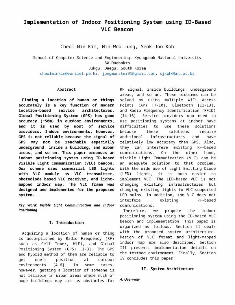
A. Testbed Environment
Fig. 4 Testbed Environment
We designed the testbed environment as shown in Fig. 4 which tests VLC. In the environment, LED light based VLC transmitter and Photo Diode (PD) based VLC receiver are tested. The power of light is switched by VLC module, and this makes it transmits data through visible light.
TABLE II shows the VLC format which used for testbed environment. The ID of location and VLC transmitter are used for indoor positioning.
TABLE II THE VLC FRAME USED IN TESTBED
ENVIRONMENT
ID of location(2 Byte)
ID of VLC transmitter
(2 Byte)
MAC address of upstream channel(6 Byte)
0x0001 0x0001 0x64E599F796D4Security key for upstream channel (10Byte) CRC16 (2Byte)
0x0102030405060708090A 0xB089
They will be server that issued ID values. The MAC address of upstream channel and security key for the upstream channel are used for later use. They are used when the VLC receiver needs to communicate aggregation agent. The CRC16 field is for validation of VLC frame.
B. Implementation
Fig. 5 shows the VLC transmitter which we implemented. Data should be encoded because the visible light is an analog signal.
Fig. 5 The VLC Transmitter which we implemented.
We used PWM to encode data and Fig. 5 shows the encoded data sent through visible light. As shown in Fig. 5, both PD-based VLC receiver and digital camera can be used as VLC receiver.
Fig. 6 shows that the PD-based VLC receiver receives the data that were sent through visible light. The PD-based VLC receiver receives the data and checks whether the data is valid using CRC16.
When the data is valid, the data is sent to the upper layer, and finally, we can use the received data. Fig. 7 shows the data sent from the VLC receiver.
Fig. 6 PD-based VLC receiver which receives data.
Fig. 7 The valid data received from VLC receiver
IV. ConclusionsFinding the position of human or things is commonly done
by GPS. For some cases, however, especially in underground areas, inside buildings, and urban areas, acquiring positions by GPS are not reliable.
Our study proposes the indoor positioning system using the ID-based VLC beacon. The server, Aggregation Agent (AA), VLC Transmitter, and VLC Receiver are used in the proposed system. The VLC transmitter uses IEEE 802.15.7 as a beacon and IEEE 802.15.4 as a configuration channel. In the testbed experimentation, a LED light based VLC transmitter and PD based VLC receiver are used. We also confirmed that our design of VLC system was working. We plan to implement the rest part of our proposed system in the future.
AcknowledgmentThis study was supported by the BK21 Plus project (SW
Human Resource Development Program for Supporting Smart Life) funded by the Ministry of Education, Korea (21A20131600005) and the National Program for Excellence in SW supervised by the IITP (2015-0-00912), and National Research Foundation of Korea (NRF) funded by the Ministry of Education (NRF-2017R1D1A3B03032156)
References
[1] P. Misra and P. Enge, Global Positioning System: signals,

measurements and performance second edition, Massachusetts: Ganga-Jamuna Press, 2006
[2] B. Hofmann-Wellenhof, H. Lichtenegger, and J. Collins, Global positioning system: theory and practice, Springer Science & Business Media, 2012
[3] J. Bao-Yen Tsui, Fundammentals of global positioning system receivers: a software approach, John Wiley & Sons, 2005
[4] P. A Zandbergen, “Accuracy of iPhone Locations: A Comparison of Assisted GPS, WiFi and Cellular Positioning”, Transactions in GIS, vol. 13, issue s1, pp. 5-25, June 2009
[5] S. Zirari, P. Canalda, and F. Spies, “WiFi GPS based combined positioning algorithm”, in Wireless Communications, Networking and Information Security (WCNIS), 2010
[6] M. Ibrahim and M. Youssef, “CellSense: A Probabilistic RSSI-Based GSM Positioning System”, in Global Telecommunications Conference (GLOBECOM 2010), 2010
[7] S. Woo, S. Jeong, E. Mok, L. Xia, C. Choi, M. Pyeon, and J. Heo, Application of WiFi-based indoor positioning system for labor tracking at construction sites: A case study in Guangzhou MTR, Automation in Construction, vol. 20, issue. 1, pp. 3-13, Jan. 2010
[8] F. Evennou and F. Marx, “Advanced integration of WIFI and inertial navigation systems for indoor mobile positioning”, EURASIP Journal on Applied Signal Processing, vol. 2006, pp. 164, Jan. 2006
[9] B. Shin, K. Lee, S. Choi, J. Kim, W. Lee, and H. Kim, Indoor WiFi positioning system for Android-based smartphone, in Information and Communication Technology Convergence (ICTC), 2010
[10] A.Bose and C. Foh, “A practical path loss model for indoor WiFi positioning enhancement”, in Information, Communication & Signal Processing, 2007
[11] J. Hallberg, M. Nilssoon, and K. Synnes, “Positioning with Bluetooth”, in 10th International Conference on Telecommmunications, 2003 (ICT2003), 2003
[12] Y. Wang, X. Yang, Y. Zhao, Y. Liu, and L. Cuthbert, “Bluetooth positioning using RSSI and triangulation methods”, in Consumer Communications and Networking Conference (CCNC), 2013
[13] Tiago M. Fernandez, J. Rodas, Carlos J. Escudero, and Daniel I. lglesia, “Bluetooth Sensor Network Positioning Systemm with Dynammic Calibration”, in Wireless Communication Systems, 2007 (ISWCS) 2007, 2007
[14] Samer S. Saab and Zahi S. Nakad, “A Standalone RFID Indoor Positioning System Using Passive Tags”, IEEE Transactions on Industrial Electronics, vol.58, issue 5, May 2011
[15] A. Bekkali, H. Sanson, and M. Matsumoto, “RFID Indoor Positioning Based on Probabilistic RFID MAP and Kalmman Filtering”, in Wireless and Mobile Computing, Networking and Communications, 2007 (WiMOB 2007), 2007
[16] F. Seco, C. Plagemann, Antonio R. Jiménez, and W. Burgard, “Improving RFID-based indoor positioning accuracy using Gaussian process”, in Indoor Positioning and Indoor Navigation (IPIN), 2010
[17] IEEE Standard for Local and Metropolitan Area networks – Part 15.4: Low-Rate Wireless Personal Area Networks (LR-WPANs), IEEE Std. 802.15.4, 2011
[18] IEEE Standard for Local and Metropolitan Area Networks – Part 15.7: Short-Range Wireless Optical Communication Using Visible Light, IEEE Std. 802.15.7, 2011
[19] The Constrained Application Protocol (CoAP), RFC 7252, Internet Engineering Task Force (IETF), June 2014
[20] Hyppertext Transfer Protocol – HTTP/1.1, RFC 2616, Internet Engineering Task Force (IETF), June 1999


![%Template for producing VLSI Symposia proceedings€¦ · Web viewSir Alfred Joseph Hitchcock [4] is called a god of suspense movie. He used POV shot a lot in his movies as the expression](https://static.fdocuments.in/doc/165x107/5b9d7dc709d3f2de128c61cd/template-for-producing-vlsi-symposia-web-viewsir-alfred-joseph-hitchcock-4.jpg)
