Temperature distribution in a metal hollow cylinder of … · Calhoun: The NPS Institutional...
56
Calhoun: The NPS Institutional Archive Theses and Dissertations Thesis Collection 1948 Temperature distribution in a metal hollow cylinder of finite radius under unsteady state conditions Knox, Robert Junior Annapolis, Maryland: Naval Postgraduate School http://hdl.handle.net/10945/31614
Transcript of Temperature distribution in a metal hollow cylinder of … · Calhoun: The NPS Institutional...

Calhoun: The NPS Institutional Archive
Theses and Dissertations Thesis Collection
1948
Temperature distribution in a metal hollow cylinder of
finite radius under unsteady state conditions
Knox, Robert Junior
Annapolis, Maryland: Naval Postgraduate School
http://hdl.handle.net/10945/31614

TEMPERATURE tISTRIBUTION IN A M.ETAL HOLLOW CYLINDER OF
FINITE RADIUS UNDER TmSTEADY STATE CONDITIONS
by
Robert Junior Knox
Lieutenant Commander, United States Navy
Submitted in partial fulfillment of the requirements for the degree of
MASTER OF MECHANICAL ENGINEERING
United States Naval Postgraduate School Annapolis, Maryland
1948

This work is accepted as fulfilling ,
the thesis requirements for the degree of
MASTER OF MECHANICAL ENGINEERING
from the
United States Naval Postgraduate School.
- Sr. Prof. P. J. Kiefer
Chairman
Department of Mechanical Engineering
Approved:
Academic Dean
1

PREFACE
The u. s. Naval Engineering Experiment Station,
Annapolis, Maryland has recently run tests to determine
the effects of thermal shock on steam piping for naval
use. After several preliminary tests, data were taken
for a section of pipe heated by the flow of saturated steam
through the pipe. Thea e da:ta cons is.tad of temperature
readings at the inside and outside walls of the pipe
at time intervals of five seconds. The calculations
of the stresses set up by thermal shock require a know
ledge of the temperature distribution in the wall at all
radii.
With the hope of assisting the Engineering Experiment
Station in the evaluation of these test data, the author
chose the task of finding the means of determining temper
ature distribution in a pipe wall at unsteady state con
ditions.
The author wishes to express his deep appreciation
to those who ~ave aided in this investigation. He is
especially grateful to Associate Professor George H. Lee,
u. s. Naval Postgraduate School, without whose assistance
and continued guidance this investigation would not have
been carried out and for his careful review of the complet
ed manuscript.
The author is also grateful to the Engineering
ii

Experiment Station and its Doctor William c. Stewart for
suggesting the investigation and cooperating to the fullest
in furnishing data. He wishes further to express apprecia
tion for the counsel of Doctor Warren M. Rohsenow, Mass
achusetts Institute of Technology, Cambridge, Massachusetts.
iii

TABLE OF CONTENTS
Title
Certificate of Approval.
Preface.
List of Illustrations.
Table of Symbols and Abbreviations.
Chapter I Introduction.
Chapter II Origin of the Data.
Chapter III Analytic Solution.
1. The general solution.
2. Solutions to similar problems.
3. Further investigations.
Chapter IV Graphical Solution.
Page
1
11
v
vi
l
5
8
9
10
14
19
1. Available methods. 19
2. A graphical solution of the EES problem. 20
Bibliography
Appendix I
Appendix II
Appendix III
Appendix IV
Appendix V
Appendix VI
iv
23
25
28
30
33
35
36

LIST OF ILLUSTRATIONS
Figure Title
1 Temperature vs. time graph; heating medium, saturated steam.
2
4
5
6
Temperature vs. time graph; heating medium, superheated steam.
Temperature VS• time graph; heating medium, exhaust gas •.
Temperature vs. time graph; induction heating.
Temperature vs. time graph; heating medium, exhaust gas.
Temperature vs. time graph; heating medium, saturated steam.
Page
40
41
42
7 Direct graphical solution (detailed). 44
8 Temperature vs. time graph; heating medium, saturated steam. 45
9 Basis for a graphical solution. 30
10 Scale for the direct graphical method. 33
11 Temperature vs. radius; heating medium, exhaust gas. 46
12 Direct graphical solution (rapid) •. _ 47
.. v

TABLE OF SYMBOLS AND JU3BREVIATIONS
B - British thermal unit
c - specific heat - B/lb/F
E - Modulus of elasticity in tension and compression
F - degrees fahrenheit
f - unit surface conductance - B/ft2 hr F
h - f /k ft-1
Jn - Bessel function first kind, order n.
k - Thermal conductivity - B/hr/ft2/ft/F
Nn - Bessel function (Neumann) second kind, order n.
n - any integer
r - radius
ra - inside radius of a hollow cylinder
rb - outside radius of a hollow cylinder
t - time
Yn - Bessel function second kind, order n.
o( - diffusivity - k/cf' in2/sec.
/5' - coefficient of expansion
~l - instantaneous surface temperature
Ae - small finite difference in temperature
Ar small finite difference in radius
4t - small finite difference in time
e - temperature
9a - temperature at inside radius
eb - temperature at outside radius
vi

er±.4r - temperature at same time at r + Ll r and at r-Ar.
Qt - temperature at time t.
Gt±P. t - temperature at time t + Ll t and t- flt at any one radius. ·
G/\ - temperature at sur£ace j\.
g - temperature at same time at A+dA and ~-~/\. .i\t.ftA.
./\. -- 1n r/ra•
- Poisson's ratio (unit lateral contraction/unit axial elongation).
- density - lb/in3.
<Jr - radial stress.
6'f" -- tangential stress.
~ - any £unction.
B&S -- Brown and Sharpe.
Cr - chromium.
EES - Engineering Experiment Station.
rt - £eet.
hr - hour.
I.D. - inside diameter.
IPS - inside pipe size.
in - inches.
ln - logarithm to Naperie.n base.
log - logarithm to base 10.
Ni - nickle.
O.D. -- outs:ide diameter.
psi - lbs/in2.
oO - in£inity.
vii

CHAPTER I
INTRODUCTION
A metal pipe initially of uniform temperature, is sub
jected to thermal shock by the sudden passage of a heating
medium through the pipe. What the temperature distribution
is in the pipe wall before steady· state conditions are at
tained is the subject of this investigation. The author
first became aware of this problem in August 1947 during
an informal discussion with Doctor W. C. Stewart of the EES.
Thermal shock in the operation of a Navy steam propul
sion plant is an abnormal condition. The possibility of
thermal shock conditions through a casualty is however always
present. High temperature shock can be the result of failure
to properly "warm up" a main steam line before admitting high
pressure saturated steam from the boiler. Cold shock can be
the result of "carry-over" of a water slug from the boiler into
the lines which have been carrying superheated steam. The
probiem was assigned the EES for investigation.
By August 1947 the EES had obtained a sizeable amount of
data from cyclic thermal shock tests. These tests were run on
various sections of pipe to determine the physical effects of
cyclic thermal shocking. Heating ha.d been accomplished by
using exhaust gases, superheated steam, saturated steam and
induction coils. Saturated steam produced the greatest temp
erature gradient through the pipe wall and therefore the
1

greatest shock. Cooling had been done by water or com
pressed air.
Most of the tests indicated temperature readings only
for thermocouples located at the inside and outside walls.
A_few test specimens were fitted with three thermocouples,
the third thermocouple being located at the mean radius of
the pipe wall. The reading of the thermocouples were taken
at time intervals of five· seconds.
Calculations of .thermal shock stresses had been made
by the EES for representative tests. The author disagrees
with calculations made by the EES for the determination of
temperature distributions in the pipe wall in the unsteady
state condition. Their means of solving for the temperature
gradient is a graphical solution accomplished by a step-by
step method of averages for layers taken such that r 2/r1 =
r1/ra~ a constant. The method fails to fit the data when
the outside wall begins to increase in temperature. In
the particular problem discussed in this paper that con
dition arises at time equal to six seconds. To allow for
this inconsistency the EES progresses by adjusting the data
to agree with the boundary conditions.
Literature dealing with the analytic solution of
temperature distribution in a hollow cylinder is limited
to highly idealized problems. Peculiarly, all published
solutions have one connnon boundary condition, namely,
an instantaneous surface heat source which maintains the
surface at a constant temperature. This condition is not
2

present in the EES problem nor in any other actual problem.
The combination of three conditions is the cause for
the complexity of thi.s .particular problem. These three
conditions are: l} steel pipe has a high thermal conduc
tivity; 2) the heat source in the EES problem produces a
variable surface temperature and; 3) the heat source pro-
duces a variable rate of change of the surface temperatureo
The analytic solutions published in the literature are of
little value as related to the EES problem.
Graphical solutions in the literature are developed
for the elementary boundary conditions only. The theory
of these, however, can be applied to the EES problem. The
author carries out this application for the case of heat-,_
ing only and presents results which he feels are more accurate
than those obtained to d~te by the EES.
Attempts to find an analytic solution have proven un
successful. In the light of the authors investigations,
there does not appear to be an analytic solution to this
problem at present.
It has become quite obvious, as a result of this
investigation, that more detailed data should be taken in
future tests. The installation of several thermocouples
at proper radial points in the pipe walls would be desir
able. The maximum temperature rate and consequently the
maxlmum thermal shock in the test occurs within five seconds
after heating begins. Automatic recording devices attached
3

to the thermocouples may be the answer to better data in
the critical time interval.
The numerical results in this paper are only as
reliable as the data taken. J..11 values of temperature
prior to a time of five seconds have been obtained by
extrapolation. A plot of the data taken when three
thermQcouples were installed in the test indicates a
lag in the temperature readings.* This may be an error
introduced by the use of thermocouples. The lag on the
other hand may be only the result of personnel errors in
taking the temperature readings. It is necessary there
fore to consider the value of this paper primarily in
terms of the theory presented and its application to a
specific problemo
* C.f. Appendix V.
4

CHAPTER II
ORIGIN OF TEE DATA
Tests were run on a length of 25-20 Cr-Ni, 3/4 inch
IPS, schedule "double extre. strong" pipe using saturated
steam, superheated steam and exhaust gas as the heating
medium. The resultant curves of inside and outside
temperatures vs. time are shown in figures 1, 2 and
3 respectively.
One thermocouple was peened to the outside wall at
mid length of the tubeo Another thermocouple was brazed
to the bottom of a ~ inch diameter hole drilled to within
0.01 inch of the inside wall, 1/8 inch distance from the
peened in thermocouple. In the test with exhaust gas,
however, the latter· thermocouple was pressed against the
bottom of the hole by means of an 18-8 Cr-Ni steel screw
insulated from the thermocoupleo The thermocouple wire
used was No. 29 B & S gage iron-constantan. The inlet
and outlet pipes carrying the heating medium were drawn
up tightly against the counterbored ends of the test
sample by means of bolts secured to flanges welded to the
pipese Insulating gaskets were placed in the counter
bored ends of the test sample to I!linimize heat transfer
due to conduction.
The specially bladed turbo supercharger wheel at the
EES was employed_to supply the combustion gas using gas
5

temperatures ranging from l040F to 1360F. Other runs
were made by passing superheat~d steam at 500 psi pressure
and 1050-1070F temperature through the sample. A third
set of test runs was made by passing saturated steam at
500 psi pressure and 470F temperature through the teat
pipe.
In addition to these runs a series of tests was
made on a similar sample of 18-8 Cr-Ni steel pipe, 3 1/4
inch O.D. and l 3/4 inch I.D. with thermocouples located
.o4r inches and .403 inches from the inside wall and
a third peened to the outside wall. Thermal shock
was created by means of induction heating. A plot of
the temperature vs. time curves for all three thermo
couples is shown in :figure 4.
Runs were also made on an 18-8 Cr-Ni pipe, 3 1/2
inches o.D. and 2 inches I.D. with thermocouples located
.01 inches and .306 inches from the inner wall and a third
peened to the outer wall. Thermal shock was created
by means of exhaust gas at temperatures ranging :from
1260-1450F. A plot of the temperature vs. time curves
for all three thermocouples is shown in :figure 5.
The results of these tests clearly indicated that
saturated steam produced the greatest rate of temperature
rise. Thermal shock tests were then planned using sat
urated steam as the heating medium. A section of two
inch 25-20 Cr-Ni pipe 1.189 inches outside radius,
6

.749 inches inside radius was set up for test in the same
manner as the initial tests. Thermocouples were located
· as for the previous test runs with saturated steam. A
representative plot of the resultant temperature curve is
shown in figure 6.
7

CHAPTER III
ANALYTIC SOLUTION
To calculate the thermal stresses in a finite hollow
cylinder the following formulae given by Timoshenko ( 16 )~·
are used:
(1) 0:= BE t c1- 7J >r2
It is_ not the author's intention to show the
derivation of the above formulas since they follow a
straight fot>ward method and are presented clearly by
Timoshanko'. The only purpose in introducing them is
merely to show their relation to the temperature dis
tribution in a thick cylinder.
To solve the integral .J"Grdr it is necessary to
obtain the temperature distribution through the pipe
wall. It is therefore necessary to determine the
analytic solution or to use a graphical method of
solution._ The Schmidt graphical method for a slab
* Numbers in brackets refer to bibliography.
8

(14)(13}(11) can be adapted to a cylinder wall but large
errors are introduced during the early stages of the
solution.
The maximum thermal stresses will occur in the early
stages of heat transfer. It is therefore readily seen that
an analytic solution is more desirable than the Schmidt
graphical solution.
1. The general solution.
Assume the initial uniform temperature of the body as
zero, the boundary conditions of the problem are:
at t = O and r :: r a
at t = O and r > r a
at t=t and r=r a
at t :::: t and r>r a
e =O.
e = o. e = ¢ Ct)
a . Q=¢ (t) , r
The differential equation for heat conduction in a
cylinder (Fourier-Poisson) when radial changes only are
observed is:
( 3) 1 r
~ Q ) Jr
A general solution is obtained by assuming Q = R T where R
is a function of r only and T is a function of t only.
Differentiating and substituting:
9

{4) l o<.T
::: _l c-~~ +~ JR\_ R d r 2 r dr J -
where_/{ 2 is any arbitrary constant.
2
-/
A general solution therefore since T ::= e (Cl -.<;,}t)
and R :::A1J0 (,;< r) + B1N0 (,){r)
is~
oO
(5) Q = I ~J 0{/ r) +BN0 (__,,.u r)
I
where A and B are constants of integration.
A particular solution occurs at steady state when
JQ/ J t = 0 the solution having the form:
( 6) e = c log r + D
where C a.nd D 9.re constants of integration.
Under the conditions where the pipe wall eventually reaches
a steady state cpndition the general solution is;
oO
(7) Q =-C log r +D - I. ~ ... J0(~ r) + BN0
(/fr) e-o<.A2
t I
2. Solutions to similar problems.
Barker (1) and Lees (9) give the steady state
temperature distribution which is of interest but of little
value.
Barker's form:
10

(8) e
Churchill (3) and Williamson and Adams (l?) present
papers which give the analytic solution for the transient
temperature distribution in a solid cylinder. The initial
tempera.ture is uniform. The surf'ace temperature rises
instantaneously to a given temperature and is maintained
at that value.,
Williamson and Adams form:
(9) [
l - 2 ) ao Jo (.unr/l']) )
fJnJ1 <µ. n> /11=/ .
where A is the nth root of J 0 (J>·):::: o.
Carslaw and Jaeger (2)* give a solution for the case
of the infinite hollow cylinder.
Boundary conditions:
at t =O and
at t) 0 and
Solution:
r=:r ; a
r=r ; a
* c .r. Appendix I
e=o 9= 9 l
11

Dahl (4) gives a solution for the case of the finite
hollow cylinder. The initial temperature is uniform. The
inner surface temperature is suddenly raised to a value
and maintained at that value. The outer wall temperature
is maintained at the initial temperature.
Boundary conditions:
at t::: 0 and r=r8 ;
at t=O and r> ra;
at t=t and r= rar
at t=t and r= rb;
Solution:-
( 11 ) Q. = 91 log I'bf r log rb/'ra
9 ==91
9=0
Q =91
Q :::o
n=oo
L 2 J ( r ) -~ t - a[J ( 11 r} _ , __ o CAn b N r 11 r ~ e Pn -n o y-·n N ( .u ,...,,__ ) o v--n
n=l oy n-o
12

Where_µ has the values of the positive roots of:
(llc}
Jahnke und Emde (6) present excellent tables for the
evaluation of bothp and the first two orders of N.
Carslaw and Jaeger (2) also present the case of a
finite hollow cylinder. The inside surface temperature
is raised instantaneously and maintained constant. The
outer wall is adjacent to an infinite fluid which maintains
its temperature constant at a point distant from the
outer wall.
Boundary conditions:
at t = 0 and r a~ r L rb; e = O
at t > O and r = r a ; Q = G1
at t > o and r = rb ; }Q/c} r + f /k ( e) = o
where f is the unit surface conductance.
Solution:
13

where fln are the positive roots of:
( 12al J 0 (,,U. r al [hY0 ()-' rbl - µY1 (ft rbl] -
Y0 (,..Ur al [ hJ 0 ( }A rb) - )"-J 1 (prb] - 0
where h is the ratio f /k.
Jo Further investigations.
Dahl's equation appeared to be applicable at first.
Upon further investigation it was found that the actual bound-
ary conditions were not in agreement with Dahl's boundary
conditions. P..n attempt to apply temperature differences in a
step-by-step manner failed at the second step since Dahl's
equation no longer applied without an initial uniform temp
erature distribution. Further consideration of Dahl's
equation was therefore abandoned.
For any one radius in the EES problem Q = ¢( t) is of
the form of Froelish's equation (18) for the saturation
curve.
(13) x t Q=----y + t
where x and y are arbitrary constants to be determined from
the shape of the curve.
14

At t ::: 00 and r=r . Q := Q a' a
at t =ex> and r = rb; Q:: Qb
at t ::oO and r a<. r < rb; Q =Barker's steady state distribu-
ti on. If the general solution were: 00
(14) Q=C+ I~J0(_;«r) + BN0(/rIT
I
then at t = o0 the second term disappears. Let C equal the
steady state condition and the final boundary condition
is satisfied. Although both inside and outside wall temp
eratures are functions of time; they also satisfy this
boundary condition. They become constant at infinite time.
At time equal to zero and r= rb the Barker term becomes
zero (initial temperature) and the constant B of the Bessel
term can be evaluated. Also at time equal to zero and
r ~ra,/< must satisfy the roots of the Bessel term in the
above equation. It now remains only to evaluate the con
stant A. This unfortunately is impossible. At zero time,
zero temperature, r = r, there exists only the value of zero
for A and the solution thus fails.
This practical problem fails to produce the very con-
venient boundary condition of an infinite surface heat
source. The EES is working ·with iron pipe of very high
thermal conductivity. The problem primarily is centered
around the initial two or three second period of time.
Boundary conditions used by Dahl (4) or Carslaw and Jaeger
15

(2) cannot be assumed. The problem cannot be stretched as
in the case of Perry and Berggren (12) who carefully choose
the cork lagging on a metal pipe and then work only with
the cork cylinder •.
Another particular solution is to let JQ/~t = c1 •
The solution of the differential equation is then:*
(15)
Where B1 and D1 are constants of integration;· e-= Q8
- eb.
Another general solution therefore might be:
(16) 9r.+B11n r +D1 +c1~ -r ~J0~r) + BN0 (/lr~ e-"'J'2t
This equation can b~ used only for a limited time since the
first term increases with time. The entire solution breaks
down on a substitution of initial conditions. At all values
of r, time equal to zero, the first term and the temperature
difference.Cea - eb) are both zero. Again A equal to zero
is the only choice for evaluating A.. Unless e is considered
as ea- 9b1 the solution is merely for a condition in which
all temperatures are rising at the same rate at all radii.
For a perfectly insulated outer wall the problem is
only slightly modified.. The outer and inner walls rise to
* c.£. Appendix II
16

the same value at infinite time. The Bessel term of the
general solution for the differential equation is alone
not enough since it becomes zero at infinite time. Assume
a general form:
00
(17) e =.!S(r,t) -L~Jo(}'r) +- BNolf'r~ I
where ,0 (r, t) -= c2 when t =. o0
and g5 ( r, t ) = O when t = o.
Boundary conditions again permit evaluation of B and j>-,
but again all terms go to zero when we attempt to evaluate
the constant A.
Assume the solution of the differential equation to
be Q =R+ T., Differentiation and substitution results in:
(J.8)
On inspection it is seen:
(19)
thus the result is the same as the solution of ae/~t-== cl. As a result of the above L.'1.vestigation there does not
appear, applying the above approach, to be an analytic
solution to the EES problem. Through necessity, rather than
17

through preference, an attempt will be made to find a
graphical solutiono

CHAPTER IV
GRAPHICAL SOLUTION
1. Available methods.
·Schmidt's graphical method (14) is basically for a
slab. It can be adapted to the cylinder, but as previously
stated, it is very much in error during the early time in
tervals. Williamson and Adams (17) point out, and Fishenden
and Saunders (5) confirm the fact, that Lord Kelvin's (10)
probability integral more nearly approximates the initial
thermal wave penetration. This improvement over the Schmidt
method was further advanced by Perry and Berggren (12).
They determine a. graphical solution for the heat flow
differential equation for cylinders using small finite -
differences.* This graphical solution is developed only
for the problem of a hollow cylinder with an instantaneous
surface heat source. The inside wall temperature is then
maintained constant. Conduction to an infinite fluid is
assumed to take place at the outer wall. The results
are compared with values obtained by using Carslaw's
and Jaeger's formula for the same condition.**
The equation given by Perry and Berggren is for the
temperature rise during a time interval at any given
* C.f. Appendix III
**c.r. Chapter III, equation (12).
19

radius (12) (7). It is merely a weighted mean value of
the temperature of the two adjacent radii before the time
interval, namely:
For very sma11·values of ~r or as ~r~o the equation
agrees with Schmidt's equation for a slab (14):
The initial curve following the Lord Kelvin probability
integral or Dahl's equation* could be used over that first
small time increment. Assume an instantaneous rise of
temperature at the inner wall for the short time increment.
The outer wall will remain at the initial uniform temper
ature. Where !). t is. very small Dahl's equation has little,
if any, advantage over Lord Kelvin's integral.
2. A graphical solution of the EES problem.
It is desirable to have small increments of ~r.
** Since Jt is proportional to Ar2 , tbe error of the graphical
* C.f. Chapter III, equation (11) ** C.f. Appendix III.
20

solution can be reduced to a minimum by a proper choice
of!). r. By progressing through the graphical analysis
using a tedious mathematical solution for each point, an
accurate curve can be drawn. In the EES problem the outer
surface temperature increases with the inside temperature.
It is desirable to prevent a dip in the curve below the
outer wall temperature. Any temperature which graphically
is determined to be below the outer surface temperature
will automatically be given the same temperature as the
outer surface. This condition will occur during early
time intervals near the outer layer. An attempt to fair
in a curve would introduce possible errors on the unsaf'e
side of the actual temperature distribution curve. It
is considered better therefore to introduce a slight
safety factor by using the suggested procedure mentioned
above. A, similar procedure is used by Sherwood and Reed
( 15) for the ·slab.,
Jakob (7) and Perry and Berggren (12) give proof
that a scale of Ar plotted as J')J\.., where . .i\""' ln r/r a'
can be used in a plot against temperature to produce
a direct graphical method of solution.* The temperature
rise in a cylindrical segment for a time interval ~t
can be obtained merely by drawing a straight line on
the graph between et, A -Ll.I\. and et, il +- A A • The
intersection Qt+ A t, ./\. is the desired temperature.
* c.r. Appendix IV
21

A careful evaluation of the problem graphically
yields the results as shown in figure 7 and figure B.
It appears, therefore, that the graphical solution
suggested by Perry and E3rggren as applied to the EF.3
problGm is the only solution if it is desired to main
tain the complex boundary conditionso It is also a
solution which can be calculated with comparative ease
by a direct graphical method.

BIBLIOGRAPHY
1. , Barker, L.H. The calculation of temperature stresses in tubes. Engineering. 124:443, October 1927.
2. Carslaw, H.S., and Jaeger, J.C. Some two-dimensional problems in conduction of heat with circular symetry. Proceedings of the London mathematical society. 2:46:361-388, 1940. .
3o Churchill, R.V. Modern operational mathematics in engineering. New York, McGraw-Hill, 1944.
4. Dahl, o.G.c. Temperature,, and stress distribution . in hollow cylinders. Transactions American society of mechanical engineers. 46:161-208, 1924.
5o Fishenden, M., and Saunders, O.A. The calculation of heat transmission. London, H.M.Stationery office, 1932.
6. Jahnke, E.) und Emde, R. Funktionentafeln mit formeln. und kurven. New York, Dover, 1943.
7. Jakob,· M:. Fortschritte der warmeforsohung. Zeitschrift des vereines Deutscher ingenieure. 75:969, 1931.
-
8. Jakob, M., and Hawkins, G.A. Elements of heat transfer and insulation. New York, Wiley, 1942.
9. Lees, C.H. Thermal stresses in solid ~nd in hollow circular cylinders concentrically heated. Proceedings Royal society of London, A:l01:411-430, 19220
lOo Lord Kelvin (Sir vVilliam Thomson)• Mathematical and physical papers. III:435, Cambridge University press, 1882-19110
11. McAdams, W.H. Heat .transmission. New York, McGrawHill, 1942.
12. Perry, R.L., and Berggren, ';l.P. Transient heat conduction in hqllow cylinders after sudden change of inner-surface temperature. University of California publications in engineering, 4:3:59-88, 1944.
23

13. Schack, A. (Translated by H. Goldschmidt and E.P. Partridge). Industrial heat transfer. New York, Wiley, 1933.
14. Schmidt, E. Ueber die anwendung der differenzenrechnung auf technische anheiz- und abkuhlungsprobleme. Foeppls festschrift. Berlin, Springer, 1924.
· 15. Sherwood, T.K., and Reed, c.E. Applied mathematics in chemical engineering. New York, McGraw-Hill 1
1939.
16. Timoshenko, s., Theory of elasticity. New York, McGraw-Hill, 1934.
17.
18.
Williamson, F. D., and Adams, L. H. Temperature distribution in solids during heating and cooling. Physical review, 14:99-114, 1919.
Woodruff, L. F. Principles of electric power transmission and distribution. New York, Wiley, 1938.
24

·APPENDIX I
Carslaw and Jaeger (2) present the following solutions
in their paper "Some two-dimensional problems in conduction
of heat with circular symetry".
2t Cylinder of radius a, initial uniform temperature o, surf ace tempera~ure suddenly brought to Ql and maintained
constant.
J. Infinite hollow cylinder of radius a, initial uniform
temperature o, inner surface temperature suddenly brought
to e1 and maintained constant.
5. Solid cylinder of radius a, initial uniform temperature
e1 and radiation at the surface takes place into a medium
at temperature o. 6. Infinite hollow cylinder of radius a, initial uniform
temperature e1 and radiation takes place into a medium -9.t
temperature o. 7. Hollow cylinder of initial uniform temperature o.
a) Outer surface maintained at O while inner surface is suddenly raised and maintained at e1 •
b) Inner surface maintained at O while outer surface is suddenly raised and maintained at e1 •
c) Inner surface raised suddenly to Qe. and maintained while outer surface is suddenly raised to 9b and maintained.
8. Rollow cylinder of initial uniform temperature o.
i) Outer surface suddenly raised to Qb and maintained constant while inner surface radiates to a medium of temperature ea•
* Numbers of _problems correspond to those used by Carslaw and Jaeger.
25

ii}
iii)
Inner nurface suddenly raised. to 9 and maintained constant while outer surface radiaies to a medium at temperature Qb.
Inner surface radiates to a medium at temperature 9a while outer surface radiates to a medium at temperature Gb.
9. Solid cylinder with an instantaneous heat source at
the axiso
a) Outer surface temperature maintained at Oo
b) Outer surface perfectly insulated.
c) Outer surface radiates to a medium at temperature
lOo Solid cylinder with an instantaneous surface heat
source at any radius r.
a) Outer surface temperature maintained e.t o.
b) Outer surf ace perfectly insulated.
c) Outer surface radiates to a medium at temperature
11. Solid cylinder with an initial temperature a ¢(r).
i) Outer surface temperature maintained at Oo
ii) Outer surface perfectly insulated.
o.
o.
iii) Outer surface radiates to a medium at temperature o. 12. Infinite hollow cylinder with an instantaneous surface
heat source at any radius r.
a) Inner surf ace temperature maintained at o. b) Inner surface perfectly insulated.
c) Inner surface radiates to a med.ium at temper-ature o.
13. Infinite hollow cylinder with an instantaneous surface
heat source at any radius rand initial temperature a ¢(r).
26

i) Inner surface temperature maintained at o.
ii) Inner surface perfectly insulated.
iii) Inner surf ace radiates to a medium at temper-ature o.
14. Hollow cylinder with an instantaneous surface heat
source at any radius r.
a) Inside and outside walls maintained at temperatur.e o.
i) Outer wall maintained at temperature 0 while the inner wall radiates to a medium at temperature o.
ii) Inner wall maintained at temperature 0 while the outer wall radiates to a medium at temperature o.
iii) Inner and outer walls both radiate to a medium at temperature Oo
15. Hollow cylinder with an instantaneous heat source at
any surface of radius rand an initial temperature a ¢(r).
i} Inside and outside walls maintained at temperature o.
ii) Outer wall maintained at temperature 0 while the inner wall radiates to a medium at temperature o.
iii) Inner wall maintained at temperature 0 while the outer wall radiates to a medium e. t terrrperature o.
iv) Inner and outer walls both radiate to a medium at temperature o.
27

APPENDIX II
A particular solution to the differential equation
for heat flow in a cylinder can be developed f'or ;)e/~t = a
constant. The differential equation becomes:
d2e/dr2 + l/r • de/dr = c1
Let d9/dr = y, then
dy/dr + l/r • y =C1
Let v ,,,. y/r, then
or
Since v ~y/r
dy/dr = v + r dv/dr
2v -tr dv/dr =C1
J ~ r /c1~v2v
( r2) ( C -- 2v) => B l
Since y::::: d9/dr
28
c1r 2 - 2r d9/dr = B
jc1r dr -fa dQ ::o Bf d;
c 1 r2 - 49 = B' ln r +- D
Q = i C 1 r2 + B' ' ln r t- D'
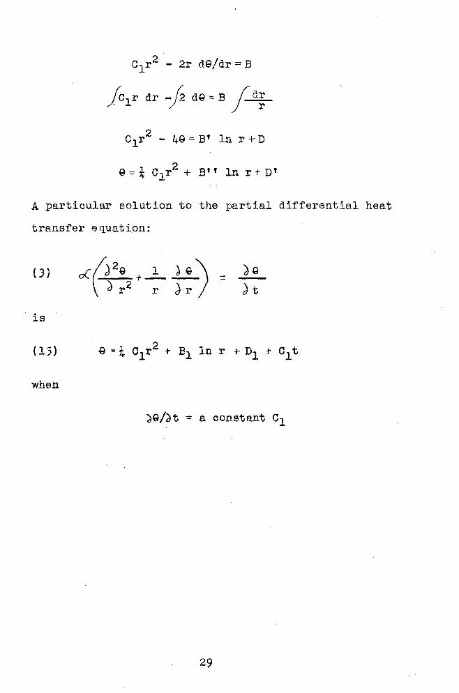
A particular solution to the partial differential heat
transfer equation:
(3)
is
when
a9/~t ~ a constant c1
29

J~.PPENDIX III
A graphical interpretation of the differential
equation for heat transfer in cylinders is presented by
Ferry e.nd Berggren ( 12}. The differential equation
when axial temperature changes are zero is: ,
( 3) = o( f-) 29 + .1:._ k) \ ~ r 2 r ';)r
In terms of small ~inite differences the above equation
becomes:
(22) A!L. = o( (.?''\ + _l_ ~) t'.lt \Li r r l.l r
e
Figure 9
Basis for a graphical solution
30

From figure 9 the following equations can be readily
determined:
1"' Qt - Qt ~= +At,r ,r
.flt L1t
.1Q Q - Qt, t,r + L1 r r- fir --::
L\r 2 Ll r
Q - Qt Q Q f\29 t 1r + /J. r Ir t 2r - t 1r- D.r
= L\ A
.1r2 !1r
Upon substituting these values into the equation of
finite differences:
1
r
Qt 2r +- A r-2Qt ,r+ Qt ,r- Ar
( L\r)2
e - Q. t , r + Ll r t , r- /J. r
2 .1 r
Let ~t = ( 4 r) 2/2o<.. , and multiplying by ( L\ r) 2 :
.31
-::.
+

2( Q -Q ) "" g -2e + g + t+llt,r t,r t,r+Ar t,r t,r- Llr
..1r -2r
(g - g t , r + a r t , r- .1 r}
(20) 9 - l. ~l+-~) 9 + {1-t+llt,r- 2 L' 2r t,r+Llr ~)9 J ~r t ,r- llr
~he resultant equation is o~e which is a weighted mean
favoring the side of increased radius and the side of
greater heat capacity.
32

APPENDIX IV
A plot of temperature vs. ln r/ra can be used for a
direct graphical method of solution.
e
t
I ~,n-.o.1\
I I I I '
. I I
I I I I I e I
't,ll I
Figure 10
I I I
Scale for the direct graphical method
From the geometry of the above figure it is apparent
that:
But from
33

r + 2
but r - 6.r/2 and r+ llr/2 are the mid radii of the two
adjacent D.r layers of ro The scale division therefore
must be inversely proportional to their corresponding
radii.
This is satisfied by choosing a scale variable
so that d/\. = dr/r or Ll A.= llr/r
The mean radius of LL\.1 is r - Ar/2 and similarly for
L1A.2 is r + t:.r/2.
Then:
Lli'3_ = ~r L1A2 :::: Llr
r - nr r+ .llr ---;r- -r
and
These value coincide with the values required by figure 10.
This scale for plotting radius therefore provides a means
of making a direct graphical solution,

APPENDIX V
A plot of steady state temperature distribution radial
ly in a hollow cylinder is a straight line when plotted on
coordinates of temperature vs. ln r/ra• The data as shown
in figure 5 represents the readings of three thermocouples
in a pipe wall. This data was replotted in figure 11 as
temperature vs. ln r/ra•
Two peculiarities are apparent upon examination of the
resultant curves. Most apparent is the change of curvature
from concave up to concave down after ninety seconds. The
second peculiarity at ninety seconds is a change from increas
ing slopes with time to decreasing slopes with time. The
latter is the effect of the wave front a·s the heat penetrates
the pipe wall.
The change from concave up to concave down indicates
at once a descrepancy in the data. Since steady state is
the ultimate condition which can exist under the conditions
of the test, the concave down curves are an impossibility.
The author is of the opinion that the plot reveals a
lag in temperature readings. This may be an error introduced
by either the thermocouples, the indicating instrument, or
both. The lag, on the other hand, may be only the result of
personnel errors in taking the temperature readings. The
existence of this lag must, however, be acknowledged.
35

APPENDIX VI
The tedious graphical solution represented by figure
7 immediately caused the author to investigate the possibil
ity of a more rapid graphical solution. A graphical solu
tion, represented by figure 12, was then made for purposes
of comparison.
The first sixteen steps of both solutions are ident
ical. Time increments in figure 12 are then rapidly in-.
creased to speed up construction. The time to produce
figure 12 was approximately one half the time required for
figure 7. A comparison of resultant values of temperatures
for r1, r2 and r3 from both figures was then made.
A maximum deviation of 6 degrees representing a 4%
error oc·cured for r1, at 1.512 seconds. This error rapidly
decreases and disappears after 6.048 seconds. For r 2
the maximum deviation was 4 degrees for a 2.8% error at 2.1168
seconds. The trend of a decreasing error at an increasing
time for that maximum error with an increase in radius was
noted for r3• At r 3 the maximum deviation was 3 degrees
for an error of 2.7%. The time was 3~628 seconds. The
deviation tends to disappear at r 2 and r 3 as time increases;
this is a trend characteristic of any graphical solution of
this type (15).
The maximum error introduced by the rapid graphical
solution is small and tends to decrease with time. Deter-
mination of the temperature distribution in a pipe wall
can be made by the rapid graphical method in two to three
36

hours. These factors should be of value to the EES who
may wish to make calculations for a series of thermal shock
tests for comparative purposes.
37

I I I
0 2.0 +o 60 80 100 TIME-SECONDS FIGURE I

1000
0 40 80 12.0 160 2.00 2.4-0
TIME - SECONDS 2.SO
I
+ _.__._ ._..__.__, -~-+-+-+-+--<~-~+-~+-+-
I
~z.o J60
FIGURE Z

0
1-+-+-11/'-t-.+-r-1H-+-1---1-+-+-+-+--H--+-+--1-+---t-+-1 _.._• _._.__.___.__._...___._.._.__._.___._._ I --~- - --- -- - ---· - -t- -t~ i - --1 - -·- - -- - - --·- -- -r -+ -!-, -l--+-+--+-+1-Hf-+--+-+- - -~- - -'---- -~-- -r- J--Hl--+--+--+--++-+--+-+---t-+--H
l-l---rf-¥'/'-+-t-HH-+-1---1--+--l--1-+--++---l---+-t-+-+--1-t-H-l---+-+4-+-+-+--f--+--I- -·- _.___.___.___._._._,_ -- -t- -t- - -:-t- - r- f---L--l4-+--+ 1--+-+-t-++-+-+ i-;,.¥+--+-t-HH-t--t--++--H--+--1--+-+--+-~-+--l--+--H-t-t--+f---H-l-H- - - - -- _ _.._ ·- _....._ _ __. -- + -t-- --·--1
-- - --~ -'-'-'_._.__.
h¥+-+-+-+~~1-t-t--t--++--H--+--1--+-t-1-T;-~4---t--rr+--+-++--H--+--1--+-'~L--~~---+---+_.___,._._L--L--,r ---~- ( ----- ' I -1- -- ~-+-+-1---1--+-+-t-++-+- - ~
f--+--•-+-++-+-+-+--l--+---+-+-++-+--l-+--1--+-+-+--1-+-+-+--+-+-+--+-+-++---+--1-l--+++-+--1-+-+---trl-l-e-+-+-+--+-i-+++--H---+--iH---t--t--++--H--f--rf--+--+++--H--+--r---+--+++f---H--+--~r+-+4--f---~l--+--~r+--+-++--+--11---1-H-*-+-+-+---H:--f--l-++-+++---Hrl-l----l--++-+-+---H-1-~r+-+-1--+-+-+--1-'--1-+---+~H--+-+-+-+-+--+~ >---+--+---+---+-+---+--+--+-+-+--+++---+--l~l-+-+--++4---+-HH-'--l-l---+--+--l---+---+--l-l--l---~+-+++---+--IH-+-+-+--l-l-+--+-+-++-+--lH-+++-+++-+-+-l-H--+-+-+--+---+--l--+-+-+-+--•--+-+-+--IY-t--+--H1 r---•__,__.1~--+---+--+--+---+->-<
40 80 12.0 160 2.00 Z40 2.SO I
Tl ME -SECONDS FIGURE '1

t-+-+-+...-++-1-t--+-t-+-+-.....,1-t-+-+-+-+-+-+-++-1-t--+-~-++-11-t--+-+-+-+-.....,1-t--+-+-+-+-+-+-++-+-+.+-1&f-''~~nft~~-f"~~~~~~·'~l~J~~~·--f--i'v"'+-'~f.a.+-+--+-1~1~~~~-L++-1-++--1-+-+-+-1-+~l-+-4--l-+-+-+-1>-l-~l-I I I ' I
t-+-t-t-++-t1-t-+-1-+-+-t-+-t-+-+-t-++-i-+-~,.ri~rt-~~,t--i~;~K~,--~;~a~tJ~TSilJ:..--•-..1+-•--~~,~__,,._.-r-<>-+-+->-+-+-+-+-t-+--+-;
~+-+-1--+-;:-+-~~-+--t-i1-t--1-11-t--1-11-t--H1-t--H1-t--H1-t--t--t-t--t--t-~-t-+-+-+-+-+-+-+-+-+-t--t-+-t-t-+-+~~·''•4•,~~·+-~'~~-U~~ - 1'4tf:p~~'--+-'~~~~.J+.J~'1~ .. ~~+-~-+-~-+-~-+-~-+--i-4-+-~-+-~-+--l--I
~T ~ Tr--+l·-t-+-1-+-t-+-+-+--t-1-+-+-t-t--t-t--t-t--+-1-t-+-t-t--+-t'--l-t-+-1r+-+--t-1
t-+-t--1f-+-+~--t-~· t-+·ht-+-t--1-t-+-t-t--t-+-+-t-++-tl-t-+-t-+-+-+-+-t-++-tt-++-i-t--t-t-+-t-+-+-t-+++-t--t-+-t-•t-t-+ = :.1 liJ t-+-+-11-t-+-l-+-+-+-+-t-+-+-11-t-+-i-+-+-+-+-t-+-+-1-t-+-i-+-+-+~ ·~-+-+-+4--t-+-·f-t-+-+++-+-+--<t-t-+-++l-~-+-+-+-+-+4-l--1--l-+-+-+-+~l-+-+-t-t-t-~-t-+ >-+-+-+-•-+-~•- -r' t-+t-- --1000 ~ -+-+-·•--+-rT-i-+-+~· t ·--r-r-t--t-t--t--t-t-t-H-1--+-+-+-+--t-t--t--t-t-HH--t-+-+-+-+--+-+-+-+-t-1
t-+-+-+-l-+-+-f4--l -1t-+-+-t--+-f-++ +-1-+-+--+-+-+-+-1-+-+-11-t-+-+-+-+-+-1-t-+-ll-+-!-t--+-+-+-1-t--+--t--+'-_ H-- - -T-+-t-+-+-1f---... ·-+- i=t-1 . +-H-r-r-1-r-r-i-t-nHrt-fi~ -t:"trkty,.._rrl I'. : _.. I I
- - Ju-+tH:H-+-++++...~-++-1-+-1-+-+-++-1-+-~-W--!4--l-+-l-+-l-+.+-i-t .--.--+-....+->--<- t· f I ...-
t-+-t-+-1-+--+--+-+-+-t-+-+-+-11-t--+-+-+-+-~4-+-+-+-+-+-t-t-+-+-11-+-l-t-+-+-+-11-+-t-l-+-+-++-t-+-lt-l--+-t-_+_-t-~-t--;-t-l-+-+-lt-+- t ,- -t_+Loo,-+-~t,.....!"'l-t-t-+-lc-+--t-1-t-t-t-1-+--+-lc-+--t-~-+-+-1-+-+.jf-+4-~~
.--.-+-+-•-~-·~ ~.:r-~~--t-'1-l-t--t-t-t--+-r-t-+-+-1t-r-t-t-t-+-r-t-+--+-t-+-+-t-t-+-+-1-+-+-t-+4 t-+-+-+-11-t-+-l-+-t-t--t-+-+-11-t-+-+-+-+--+-+-+-+-bt--+-t-t-+--1-11-t--+--+-+-+-t-t--t-+-11-t--+--t- ,_.__,__ - 1-t-+-+-1•-t·-t--+-+-t- -+ --r -- -t--M--t-t--H-t-+-l-t-+-iH-+t-t-t-+-!-++-il-++H-++-!-++-iH
L&.:aoot-+-+-~+-+--+-+-1-t;-;H-1-t-+-t-++-t-+-+-+-t-f--t-"H-r+-+-+++·-+-+-t-1-HH-t--t-+-t-+-t·-+-+-+-t-f-1~t-H-t-+-t-+~...,,..-+-+-+-1-H-+-1-+-+++++++-+-H--HH--1-+c+-1-++-+-+-+-+~--1--1~
• • w a:
·-
;
L -f- ... ~-1--
.... ..... 4il f-1-<ll '" )
1~
, __ .,:.-- -f ... :> 1--- -t-+-+--t-+-+-+-1-+-+-+-+-+--t-<t-l--+-t--+-+-+-1-+-+-hk'f-:++~H--t-+-t-t-t-1'-t·-t--1--t-t-t-.t- t-+-t-+-t-+-+-t-t-t-+-+-+-t-+-+-t-+-t'--l·-1-+-t-+--l'--l-+''.~-~~-·~,~,.t-+-l--+-t-+-+-!-+-+-l-+-+-l-lc~-
L lJ I .,. Ill r
----- -... I ~ ,_,. .... .... ... ... ....
" ....
-t-+-t-t-bf"f-t-t-t-t-+-l--t-+-+-+-t-l--f-t-t-+-t-.J-o'f'-l-+-+-!-7''f'-l-t-+-!-t-+-!-t-+-!-t-+-!-t-+-!-t-+-!-t-+-t-+-+-i-+-+-!-+-t-+
~6001--~-+-+-+-<H-+-+--H-+-+-++-+-+-IH-++-H-+-+-++-+-+-1-+-+++-+-+-+-++7+-i-+-+-++-+-+-1-++-+-+-1-+-+-++;"'f-1-+++7"'1-+-t-++-+-+-H-++-H-+-+-+-+-+-HH-+++-+-+-H-++-H-+-1-+-1 w 0..
~ ll.1 f-
.... t-•-+-+-i-+-+-t-t-t-t-t-+-+-1t-+-t-t-t-+--t~-+--+--t-t-+-~1-t--1-1r-+-+-+-1~~-r-<--+-+-1-+-4-l-f-t-+-1-+4--l-t-+.....i-+-+-1~til't-+-++-!-++-1-++-t-t-t-+-1-++-l-t-t-H-t-+-lr-+4--l--+-l--H-t-+-l-++-1-+ i-+--+-t-+-+-·>-+-t+·+--t-+-·-+-....+-t ~-+-<-+-+-<-+-+-<-+--+-<-+-~ t--+-<h.,-,;-+-+--•-+-+-<-+--+-i-+--t-t-+--+--+-<~•..-"""'"-t-+-f-t..t"'~...-+-1-++-t-t-+-+-1-++-H-t-+-t-t-+-11-++-t-t-+-t-1-t--t-1-+~-f-+-+-+-t-t-+-i~r~
-+-+-1-+-+-t-+-t-t-t-+-+-1t-+-1.,.-~L..o~"- -- ~+-+-+-+-f-+--t-t t-~f"f"+-1'-+~~i.-r-+-+-1-++-1-+-l-t-+-+-+-1-++-l-t+-+-t-t-+-lf-+--"-l-+-!-+-t-t-t-t-+-1-+--+--1-t-t-t-t-t---t-1'-t--t-1-t-t-t-+-t--.-i-t-+-t-+·-+-t-t-i 1-+-t-+-1-++-1-+-t-t-+-t-;~~ .... RJ'i-t-+-H--+-+-t-+-+'1-~-.¥'f-'f4-t-+-l~-+--t--+-+-+-l-+--t-+-+-+-t-+-+-+-lt-+-+-t-t-+-+-l-+--~~-~-·-+-11-t-+-f--+-+-t-t-+-+l-•-+-f--+·-t-t-t-+-+--'-+-+-t-+-t--t-t-t-+-l-+-I
~ .,- I
2.00 1-+-+-+-l-+-+,,1-"1-"-t-+-1-+-+-f-+-+:::ol-"f::+-+-l-+-,_.1"1--t-+-t-+-+-l-+--t-r+-+-+-+-+-+-<f-+-t-+-t-+-+-lc-+-+-r+-+-+-+-+-+-l-+-+'iMi"-f~11r"tL~1·'+'1'+-'1~~4~'-!-~1-::i-~LiL~f.ltJ'1~'rLfLfr•'i-if-t-t-1-t-+-+-t-+-+-l-+--t-f-+-+-t-l l--+-t-t-+-b~~'~4-+-1-+-l-H-hil:P"l-t-+-l-~..i""t=-+-t-+-1-++-1-++-H-t-+-IH-+-t-+-++-1-t-+-~r+-t-t-l--+-1'-++-l-+-+-+-l-t-1 t-t-.-.-+-+1 -+--+-+-•-+-<-+-+->-+-+-+-+-+---t-- -<--+-+--+-+-+-<-+-<1--~-+->-+-+-1
l--+;~~"-.t--1-+-t-:boli-1":i--b1~'1""l-t--l-1-+-+--t-1-t-+-1'-++-l-++-H-t-+-lf--r·l-t-f-l--+-1'-++-f--t-+-H-t-+-l'-++-l-++-1-t-+1 +-lf-l-+-H-t-+-1-t-+-il-++-t-t-+-+-t-++-i~Lt--•-~_._.-...-+-<_._-+-t--t---+-+-+-< ~§!'.~t't:f'.f:1t!:t:El::tjj:tj:ttj::tt::tjj:j:j:ttj::tt:::t:J=1i=t::t:l=t::tjj::tj:~:t:l=t~jj:t:t:tt=J=-t-+-4-+--+-"-~-~~- -+-+-+-+-1-r+-it-+--1>-+-+-+-~-+--t-~--+-+-t-+-+-t-t-+-+-1-t-~t-e , - - -~+-<'-+--+-->-+->-+-+--+-+-•f--~--1-~-+~ +-+-+-<-+-f--+-+-+-t-l-+-11-t--hl-f--t-t--+-i
I I I
0 · to 2.0 JO ~ 50 60 70 80 TIME - SECONDS FIGURE 4

0
>- >- -1- - ->-·>- - -t-i- -+- • • i ~-+++-H-+-+-+-'H-+++--1H-i--++-1H++H-+++-H-t--+--l--l--l-+-+--l-l--I- -:HH-++-H-++-l-l-l-+++--1H++-H-l-t--l-l-l-++WW-1-.l--l-l-!.-+-WW-LI >-<-+--+-+-+-+-+-+-+--+-<-I-- -1- ;-+-- !-Hr-t-t-t-H"-t+t-H4+t-H4-f--t-H-++t-H-++HH++-H4++-H4++-H-++-t-W-++-H4++-l-l-l-l-~-W-++--W-1--4---l-W-l--4-W-1--4---l-l ~~-1--4--4-4-+-+4-4- •-1- + t- -~-
t--+-+-+--+-+-+--+-t-t-+-4-+-+ 1:-r-t-1~--t-H-t--t-1+-t-H-t-t-i-t--t-H-t-t-i-t-+1r++t-t-~~-+-+-H++-1-+-+-~++H-t-+~44-1--t-+-+-l-+-+-1-++1--t--+-+-l-+-+-1-+-l-+-l-1--~--l--l--1-+-l-+-l-l I
~-+--+-+--+-i--+4-+-+--+-•-4-i-.-•~1-4-++-+-1---4-+-+--+-~-~-+--•-<t-t-+-+-+-<-+-+--+-t-•-+-+-+-t-l-t--+--+-~-t--+-+-<f-4+ +-+-HH-+H-+-+-H-++H-+++-1-++H-+-+-H++H-++H-+-+H-+-t- _, f N ,_ u .. '' - l I .I j.
-•-+-+-+--+-+-+--+- - -__ _,__._,__.__.___,_._._ - ·- - _....._ -+-<-l+l--l -+-++-<1-•+-1-1- - --t;' ,,,._'F-++-H-+++coJo-t"'f-... +H-+++-H-+++--1H++H-++-l-l--l--l--+-l
~~+~-1-+-+-+--1--<1-++-+-+-4f-4--+-+-+ t-1-r-t--1-1-1--+-t-1-t-t--+-t-+-<t-t--t--t-t-~-~-+-~-·----•--- ·~-1--'-~'-t--HH-+:~!'9..--+++-t-t-+-+-HH-t--t-H-+++-H+++-l-+++-~ - -
40 .80 12.0
t-r·~-+--+-+-+--+-+-+--+-+-+--+-+-+--+-+-+--+-+-+--+-+-+--+-+-+-~-+-+--+-+-+--+-+-~~C\J l-++-t--HH-+-t-+1-+-1-++-t-Hr+-l-++1-+-H-+-l--t---t--l-i-t--l-1-H4-l~
--+ ~-I
I
1-+-+--•1->--+-->--<'-~-+-<- - - --
1
160 ,oo 240 2.80 3?.0 TIME - SECONDS FIGURE 5

1-+-+-1-+-+-+-+-+-+-+~-+-+-+-·r+-t-+-+-t-+-f-t-+--+-t-+-+-t-+-+-t-+-+-t-+-+-t-+-t-t-+-t-t-+-+-t-+-+-t-+-+-t--t-t-t--t-t-t--t-1--t---t-t--t-+-t1-1-~+-+-+-+-1-1-,!- ~4 +-J-1--+-1-+--1-1-~-+-r~-+-1-++-i~- -~
f-+-+-t-+-+-t-7-+-t-1--t-r-1--t-+-t-+-+--+-+-+-t-+-+-+-rt-7-+-+-+-+-+-+-+--t-t-+-+-+--+---t-t-+--t-t--t--t-+--+--1-+--+--+-+--+--~~+-1-+-+-+-+-+-+-+-+-t-+-+-+-+-+-+-+-+-+-1-+-+-+-+-t-t-t-t~:r1-1
0 40 80 \t.O 160 2.00 240 TIME -SECONOS FIGURE 6


0 c,, 0
"' r<. ,.....
()
0
µ..j,._
Cf1 0
TE M P E R AT U R E - ° F. I'> N G.i 0 ('1 0 0 0 0
GJ Cl'! 0
.... 0 0
~ Cl) 0
w 11111 ,. ~
-UW--1--+--l:::j::::~J-+--l-+-I I I I I I I I I I I I I I I I I I I I I I I I I ll'"t+-bl I I I I I I I I I I I I I I I I t I I I I I I ~
\ ....... !'-.. I N I I I • rq; I ""' T T T ~ 1 f I I TT IT I T f TT T r-,;;i- 7 , i l ..._ T T l '\! I I I I I 1
i I i I ±- ' I I I I I I I I l..J 8-
+ -f -~
~)Tl VJ I
Ct> Cl
fTl (")
0 2 0 tr>
CD
"""" 1 I ... I r "' ~R
I j -!--' \\ '- r -~ tt:t+-1 I I '- -..., I t -- --, - - ::f r..t 1-1 I I I , J "-1---- - ' '-~--r ' _( ___ j__L_ 1 - l h-1 I I I I I I I I I I I f
L~ - \ 1-...' -t-- -· I_ ·- -- • (J : t- I ;'\. : IJ I \ I ;-;--;-- . ,, \ , "- ... f -1-- --- --- --r-r ... - ;;;I I f [ 1 I r I - - ---- - - - ---11-- I
1-Ll- ,_ - _ J\ i\~~ _ .L '"'' __ ,__,__ ~ , 'j·--...-~t-f--~•' ··- ----+--_t-:-1-~-- , ___ ),_,__, ' f---~-i-- ~-,__IT.f-H---- ~. - "'Ill
r~ " J , 1 1 . 1 , 1 rt , ' ,... n i 1 ·1
' " ... IT R"" ~ ~ r ·11:' --· ~-:_:: -~ ~-'-HI j-R'lr:-Pff,_r-LL ~ :: , __ -}}{I:::::::: ..... -. , ~~ , r , , l f-t IT, , "' _ "'".... ~-\j i i---·n·+• 'rl----- r---,- rw··t---t· - L- - .. .... /\IT--rT . l - t+--1 1- ;-L -r+-- ~- 1 -
~ : 'i ~J ++- tf+1 ~- -~~t-:~- ~~~Ii+ -n-~ tf-t-~ ~: g: ~ - 1 T TT I i I I I_ 1--J-
"I i:;o _._, 1 -> 1 __ t-+-~-q Lt'-1 Lt- tt-f i t+ _ -Ltml-I __ I! i T 11 ' ""' = ;;;;i -+- 1- ~: _j_ .l-t -t -· tL 1. ll I •• "'
--j-- - -~: -1* -1'-t '---t t ; ~· - - ; :_ - flT Lf 1 -r'-' _f--LL "" , , H- , 1+ t ' , , , . , 1 + , n- ..,. " -· i - - - - -r I - - - -r- -~ -j T • - 11- - - -y- -1-1- I . r .
-r--t-- - IEE t __ t Lr-·Lt·r Itlttt.:'. ~-r·r1i_fl ,E ........... t-h+ -- 1· +-t-- - - I -+·· - ii- .. r~+--t-u . -·-+-~- t- - i.::. _,,
i_ - - l - -- • - -:r-l ~ Y-~- ~ t 1---r· ! . ~-- • ·-•-'-+-.---!.- -~-~ -1- - ' ti. - . ~••ti'_- --r f-- i=•i-r-+i-i-t~- fhTr-t··- ;d-:_~_+-r-·-T- -r-'--.~ffi-~-f--i-iR: I' ,mllif ~t- T ,.. - ,__ --1 · • • t1-·-·- -11-r-t -· · · • ·-~--+-•-· -r ! t·1 - -f-+-i- -~ I I l .t I I I. I ' ' I I ' ' ~ -:-~ l ' I ' I . I I I
"' k.L l_ ...
± --f--- t-~1i-·---- •· - t---1::i1-r-~1 1 •t--·· :;·~_:·: :·, -011-1! h- + -t- - -'-ttt-~+~1' ~ '- - j;t+l f-1----~~f~' l ~tLI:-:: j ~ 1 g-[·-~· . ·1
:-i;; I :-.L: ~ :.1-tl' ~P-t 1-~ lt I 4 ~1-~i+gt+ - _,_-t-_ "'" --- -.-1-·11' --- I if- +-; ;fh--n- ;' ! ... 11.,11·l·.· :,_1_1IH-· it-.>--+- -t +it'i --i-
I --- rl :+---T~· ·-f--r:t ·: : ~-+ -r1·11 -~~ ·:;ri:-·; ;·-... 1 1-t· r: -~f---- ·I +-+--t-l--1H--+-_+-~+-~+-+,-++++-+--+-+-+JJ_ ~-t±:1-J:i=- .TTi:. . : --q J: l. rr tc --El:+; -; 1 :q; 1
-: ;- i.~ t ti~ ti~+ 'tT ·-" ~ • •:f--'-1 f-t -.,, -1 I .Ll-f: 1·- -l. ·r _j .... - rtt,_r, . : ; -l--1--Lft r - . , . ! .• : r-.. 1 .1.,. t' i.,. ~ ·----·-~ -_i~-f-- -Lt-•-H--- ' I It l l' l •'I' I ' "' 'L ',,,,,,,,,,,.'I'' L' H _, 1--G'> l 1 , -H- -i- -1-; 1·-- -,- r-+-r-r-r ·. • ~: ~ • -~ 1 - -I·~- ir :-i-1r· r i r l ~ .-~ ·. -1 ···- 1 l -, 1 t1 ~~t-r ;· ·
_ --·------,__,>-+-+--+-l--41-+-•-+-+-+-~--4-- rh1:-:,- r,-rt--rt•;-:- •:•-··-·· 1 7'"1. !- ·· ··-:·;---·- 1 • - • -····· ··-,-.-~r-.-t----1···-.+t
~ 0 -·-,1~1 1 1 : -·--- r-++~11---i-tH---l-r::~~, ..... , .... ~ ···;·-!··· . ..:"!.:+,·· ········· ~·-tH 1+r-H 1l'!!tt'H fTI
·_--,~R -L I I - ---1~-n1r:•i-'1- t-7-11·::-.,-11,--t-r:····•: ·1:'·-t·:··· :·•·:;·r·t·r-: ··:······t ···:trr~~·tH 'ti! lr --r- .,.____ ·1 t---i--•- l .- · ---r .......... -·-· ;.J-;:.;--+ ....... · · .. •· • t • • • · • · • • ·-·' ·- • • • • • • • • · • · .... 'i- · · ~ +-•' rt - + ::·:-,---ft-tt' -----1~- 11·-H-,:'~--1-lii'.r:fr~_i:;··:-m i~::r··· .(l);:i-·i~r ··:t::·:·'1·1t.+ 1~--t- t-~111 r·t t +trEjf·- ===~: .-T\t:¥'Tf: t l= +f+T+:: ;:.!Jt~~r:: ·:: .:-:::::::: : !: : : \i:: : : t:::::: ~ ~-r nr r++ -: ·L_.f- ~ t :trt
--U::r+· +· ; ~L - ~ _j-+t H-l-'--:-c111;: f't ;,-·tF-+~--~ ;· ·-· ~ ; ; . - .. - - .... : . r·; t • : l j.:.:. ID, .•• rr'lH ~I + ~i 'tr I ~I · __ J_ 1-~ -1-: ---r-:- - , ___ :-.-;-:- -1 i-· :·-~ r ·-·.. • ..... ·•• ''7"rt· · ·• ····• -.·:t '-t-·1- t~+·· T --,+-,---t-- I I --yr:'-' -1 r ;-;-r-+--r- ' .. •·er -·. . . . .. . •.••• ' . • • • ~ t:.. . • . - .. ~ t Tr·· --ti t I·- -, t
' '~, ' j I I I I ' I I I I I I ' ' ----- ' I ' ' ' I . I ' I ' I t rrr- -l--'-,-r-'-L l--ir- E' I i~·:-i- . ····1r·t ;•1·11~~:· ·····•tf• r!;. --<
'Ti --- -1-- l ---1-----t!---- - 1~··: · · · · · · · • r • • • • + •,. • •• - ·-··rt l T rl -- · 1-t--l-1--- -·---'-----i------ I -~·---L--·- ';.,. : . . .....•. ; l •..... t 1-:' I .. : . ; ·-· --1 f- •• ; ·_---+HI. ' - -t 't Ir- I f=oo~ r+. ;$:: ·-~·-· ;~· ·-;_ : i L[!::;: : : •t' [ i::; ~ : : : : ~itm-_' :_1t_~tt;!-_.__--!--1..-l--l-J
l I ' l I I I l-+ I t : ' ; ' I ' :---1 -IT 11 11 ••- -1 •-i:---1 •7r•• ·!~r·.~·· •·rrt--•-1, rr. I -I ' I r l I l I I • - 1- t ---r -i- • • - • • • • • - ' ' • I • • ..... • • • I • • - ... . ~
. I lt±t • •' • ' ''! ' .,, j I I I ± TT I~=-- - -· ·r .•• ; . . • ' t. : . : . . ;·: t •• ·-' • ; -;-r--n -----·
- h 111 ---- ~ -+H, , • ;-· · · · • 7 • • t • • • • ~ 1 tt t-1· · -i--,-r_...T__._ .... ~_.
()':)

IOOO,...........,......,......,...,_..r;,_,_.,..,...'l""T'"-:-T"~"!'"T","T'"'T""T'"'T""T'"'T"T1TT1'T"T"Ti'"l1"T"T"IT""T'"Tl"Tl"T.,...,~1'"Tii'rrtrtrT"rT"n-llTTTTTTTi l--l-4--l-+-1f--l-4-4-~-+--+-+--1-+-+-+-<f-i-1 -+-~'-+-+-~'-+~1f-+-f-t1 -+--t-t-11"-t-t-+-t-t-+-t--r1rt,...1 +
1-+-+-t-1--+-+-+-t-f-+-t-+-1P-t-+-t-t-1--+-t--t-t-f I
·goo
800
600
200
II t - t .... ll ~.-_, ~.!. "' ..
I ... -.. II I.:'! I I . ~ I rill' r -' I.fl + I ·--'l r.r~11- rl'I'
·~
r-11..:,...i -
'"' t ' I 111 ,,, II I ....,...., I I
r j ,-.;: .... -I i
I
I
'I
I I
1-4-+-+-+-+-r-+-~-+-~+-;-+--+-+-~,.·-t-+-t-+-1"'1-.C:::t--t-+-l~-t-t--'-r1
~:rt-t-r+-+-IH-t-t-+-t"1rt-t"'l"-t.;:t-1-t-t-t-+-t-1rt-t-t-+-t-1-t-t-t-+-t-t
, __ --1-
......
! I ' 'I'
I I .......... • L J t ..........i I
~ -.... I -- I
I ' 1 1
~--;-.._; .;_ J.+H':--t+-t-t-H-t-t-+-t-H-t-t-+-t-1-t+-t-+-t-i"'t .... d:-+-I I I '
I
I I
'·~·~· -r-T"°1 I ,..__ I I r-I I I I I ...._ I ' I ' I -·
' U...Lr -=~-..... ~crl+-t-+-H-+-t-+-hH-+-t-+-H~- ... -1-r-r1I -re- 1
I I
H+f+ - -i I '
r-1 I I
+i--++!-t ~ :-_;,;;:_
I I ii
f-1-+-+--+-+-f-i-i--t-·t=r,-~,,,...~'~"""'. lli!.~tt:-~-t!~.+-1f-!L.\•-i---+--'F"l1»-i.::1:-+-+-+-+--+-+-t-+-+-1-+-+-t-+-F"l"'+.$;;~ ... -+-+--+-+-f--l-+-+--+-+--+-+-+--+-+--+-+-+-~ +-+-.--+-t-r+-11-+-+-1~+4!'--r-'~~_.j~-l-~=:!::-t--if-+-t-t-=f,,..t-+-l:;±::J--!-+-f-t-+--+-t-+--+-!-+.+--j~'"'""'+..-.-d~t-4---+-+-+-+-+-!-+..j.....;f-+4-1-1--1--1
I 00 i-+-+-+-t-t->--;:_._~'±ti ~~:~+-+r··-;_~..,_+-+1-+-r' ~ ' --
t-i-1·-t--+-+-1--+-+-+-+-1--t-+--+-+-+-1··-~-~-t-i·-t-t·-t-t-r~::r-:11~'~111r-t-r~--t-+-11--t-+-t-+-l--l-+-t--t-+-f--l-+-+--+-+-1--+-t--1J,.."-+-l--+-t--+--+-+-1--+-+--+-+-~ , ... 1 .
... -::: •"'"'!
o ................................. ~, ........................ ~.~2i..J.. ...... .U....W...U....J.U.....U.....U.....U......L...L4..LI...LI...LI...LJ...LJ.s..LI...LI.-1.::L....!...J.....!...J.....!...J.-LI-LI-Liu..J
LN _R/RA 4·6· ,FIGURE._ ii