Temp-A-Start 2014 Installation Guide Engine Only Sec 1 Installation Guide Engine Only Sec 1 System...
38
Temp-A-Start 2014 Temp-A-Start 2014 Installation Guide Engine Only Sec 1 Installation Guide Engine Only Sec 1 System Check Out & Fixes Sec 2 System Check Out & Fixes Sec 2 Please call our 24/7 Technical Support Line If you have questions not addressed within this presentation. 309-472-0676
-
Upload
makayla-ansel -
Category
Documents
-
view
234 -
download
2
Transcript of Temp-A-Start 2014 Installation Guide Engine Only Sec 1 Installation Guide Engine Only Sec 1 System...

Temp-A-Start Temp-A-Start 20142014
Installation Guide Engine Only Sec 1Installation Guide Engine Only Sec 1 System Check Out & Fixes Sec 2System Check Out & Fixes Sec 2
Please call our 24/7
Technical Support Line
If you have questions
not addressed within this
presentation.
309-472-0676

IntroductionIntroduction Anyone using a service procedure or tool not recommended in this tutorial Anyone using a service procedure or tool not recommended in this tutorial
must first satisfy himself thoroughly that neither his safety nor vehicle safety must first satisfy himself thoroughly that neither his safety nor vehicle safety will be jeopardized by the tool/procedurewill be jeopardized by the tool/procedure
he selects. Individuals deviating in any manner from the instructions provided he selects. Individuals deviating in any manner from the instructions provided assume all risks of consequential personal injury or damage to person or assume all risks of consequential personal injury or damage to person or equipment involved. Also note that particular procedures may require the use equipment involved. Also note that particular procedures may require the use of a special tool(s) designed for a specific purpose. These special tools must be of a special tool(s) designed for a specific purpose. These special tools must be used in the manner described, whenever specified in theused in the manner described, whenever specified in the instructions. instructions.
Before starting a vehicle always be seated in the driver’s seat, place the transmission in Neutral, be sure that parking brakes are set.
• Before working on a vehicle, place the transmission in Neutral, set the parking brakes, and block the wheels.
• Before starting your install disconnect the batteries power.

This Presentation Will Cover This Presentation Will Cover The Following AreasThe Following Areas
System Overview & Installation System Overview & Installation Features, specifications, & interfacing of systemFeatures, specifications, & interfacing of systemEngine Mode OperationEngine Mode OperationQuick Testing For Engine Mode Diagnostic &Quick Testing For Engine Mode Diagnostic &Testing ProceduresTesting Procedures
Of The Temp-A-Start SystemOf The Temp-A-Start System

System OverviewSystem Overview
• TAS is an automatic start stop system• Keeps the engine in a ready to go state at all times• Reduces engine wear• Increases miles between oil changes• Provides auto control for recommended high idle RPM• Prevents dead batteries• Extends battery & starter life

INSTALL OUT LINE1. Unpack your system & in speck all components & wiring.
2. Check wire color at each side of a connector to insure that they match.
3. Give your machine a good look over to in sure that it is in good working order before you start your install.
4. Some things you may want to make a note of before you start.
A. Normal cranking time to start.
B. Is there a fast idle option on machine & is it working ?
C. Can this machine be started in gear?
5. Next on the engine locate a port for your oil temp sender.
6. Look inside the cabin for a good location to mount you main control center.
7. Decide where you will run your wiring harness & separate wires running to different locations.

TAS Direct Interface TAS Direct Interface OverviewOverview
To Electrical SystemTo Electrical System
The following components interface The following components interface directly to the vehicle electrical system.directly to the vehicle electrical system.
TAS Main Control moduleTAS Main Control module Master control relay for ign. Switch if Master control relay for ign. Switch if
used used & (2) relays inside the TAS control unit& (2) relays inside the TAS control unit

There are (3) Interface There are (3) Interface Control RelaysControl Relays
3 relays are controlled by TAS and they are:3 relays are controlled by TAS and they are: One: external Master Relay-controlling battery power toOne: external Master Relay-controlling battery power to the key switch.the key switch. Two Internal Relays located in TAS main control center. Two Internal Relays located in TAS main control center. One TAS Internal relay controls the ignition key signalOne TAS Internal relay controls the ignition key signal to the engine ECM. In normal vehicle use the key signalto the engine ECM. In normal vehicle use the key signal from the ignition switch passes through this relay whichfrom the ignition switch passes through this relay which is normally closed.is normally closed. Internal relay two provides a 12v or 24v signal for Internal relay two provides a 12v or 24v signal for
cranking. cranking.

Functions of Relays during Engine Functions of Relays during Engine Mode Mode OperationOperation
Master Relay & all Power accessory Relays are Master Relay & all Power accessory Relays are turned off approx. two minutes after TAS has been turned off approx. two minutes after TAS has been activated. The engine continues to run until all activated. The engine continues to run until all engine mode parameters are met. engine mode parameters are met.
The internal TAS relay controlling the ignition key The internal TAS relay controlling the ignition key signal remains active until all parameters are met. signal remains active until all parameters are met. The engine then returns to base idle for 8 sec.before The engine then returns to base idle for 8 sec.before shut down and the TAS system will be on stand-by shut down and the TAS system will be on stand-by waiting for a start to be called. waiting for a start to be called.
When a start is called the start alarm is sounded. When a start is called the start alarm is sounded. After the alarm the starter output relay in TAS After the alarm the starter output relay in TAS provides the crank signal.provides the crank signal.
After the engine is started the only relay remaining After the engine is started the only relay remaining active in the TAS control module is the ignition active in the TAS control module is the ignition control relaycontrol relay

System ComponentsSystem ComponentsMain Control Module (MCM)Main Control Module (MCM)
The Temp-A-Start system is The Temp-A-Start system is currently designed for operation currently designed for operation
withwith ALL types of DIESEL ALL types of DIESEL ENGINES.ENGINES.
The MAIN CONTROL MODULE (MCM) is the
heart of the TEMP-A-START system. It accepts
inputs from the various sensors located
throughout the vehicle and interfaces with
the electronic controls of your engine.
Suggested Locations
In or under dash, in the tool storage area or under the bunk. This location will vary from tractor to tractor, depending on space available.

System ComponentsSystem Components MCM ContinuedMCM Continued
Step 1
Most tractors & machines will have a place in the dash, under it or in a toolbox or storage area.
If a location such as the ones listed above are not available, securely install the MCM in a protected location where it cant be easily kicked or damaged
Step 2
Next, attach the MCM to the machine using the screws and L-shaped brackets supplied in the Kit
Step 3
Connect the main wiring harness to the MCM connector using a 7MM driver.
Check to make sure that the main wiring harness and MCM connector bundle have not come into contact with sharp metal edges that could chafe/cut the wires or insulation.
Check the color of each wire on the control center side to see if it is a match on the other side of the connector.

SystemSystem Components ComponentsAlarm BuzzerAlarm Buzzer
The engine compartment ALARM The engine compartment ALARM provides an audible alarm 15 provides an audible alarm 15 seconds before the engine starts, seconds before the engine starts, when the Driver Comfort Control when the Driver Comfort Control System is in ENGINE MODE. System is in ENGINE MODE.
Suggested Location and Suggested Location and
Installation Installation Anywhere on the engine Anywhere on the engine
compartment firewall is an compartment firewall is an acceptable location for acceptable location for installation. installation.
Secure the alarm to the firewall Secure the alarm to the firewall of the truck, using silicone of the truck, using silicone adhesive or wire ties. Route the adhesive or wire ties. Route the remaining cable to the MCM remaining cable to the MCM location where it will be location where it will be connected later in the connected later in the installation process. installation process.

System ComponentsSystem ComponentsLED Dashboard DisplayLED Dashboard Display
The indicator The indicator LED on the LED on the dashboard dashboard DISPLAY is a DISPLAY is a two color LED two color LED that indicates that indicates the status of the the status of the Driver Comfort Driver Comfort Control System . Control System . A A GREEN LEDGREEN LED indicates the indicates the system is ON, a system is ON, a RED LEDRED LED indicates the indicates the truck is in truck is in Neutral & Neutral & system is off.system is off.
Yellow Dash Sticker Included in Kit
Step 1
• Find an open area on your vehicle's instrument panel and apply the sticker shown above. Use a 1/2" drill bit to drill a hole for the DASHBOARD SWITCH and a 9/32" drill bit for the LED hole.

System System ComponentsComponentsLED Dashboard LED Dashboard Display cont.Display cont.Step 2 Step 2 From the backside of the From the backside of the
instrument panel, push the instrument panel, push the switch through the drilled switch through the drilled hole. From the front side of hole. From the front side of the panel, insert the LED. the panel, insert the LED. Tighten both components into Tighten both components into place accordingly.place accordingly.
Insert the green lead from the Insert the green lead from the LED DISPLAY into the green LED DISPLAY into the green wire of the DASHBOARD wire of the DASHBOARD Switch's plastic connector. Switch's plastic connector. Finish this step by connecting Finish this step by connecting red to red and black to black red to red and black to black at the connector from TAS.at the connector from TAS.
Step 3 Step 3 The switch and LED should The switch and LED should
appear as shown in the image appear as shown in the image to the right when installation to the right when installation is complete.is complete.
NOTE: This switch is used to turn the Control System on and off.

System ComponentsSystem ComponentsMain Wiring HarnessMain Wiring Harness
This bundle of wires This bundle of wires and connectors and connectors comprise the MAIN comprise the MAIN WIRING HARNESS . WIRING HARNESS .
Be sure the MAIN Be sure the MAIN WIRING HARNESS WIRING HARNESS connectors will reach connectors will reach the MAIN CONTROL the MAIN CONTROL MODULE without MODULE without straining the harness straining the harness and that ample space and that ample space is available to mate is available to mate the connectors.the connectors.
NOTE: Harness routing may have to be modified in some applications due to unforeseen circumstances, customer modifications and the like. Be certain to follow good engineering and workmanship practices. DO NOT COIL EXCESS WIRING, TRIM EXCESS AWAY.

System ComponentsSystem ComponentsNeutral Safety SwitchNeutral Safety Switch
This is the only part This is the only part required for a standard required for a standard installationinstallationNOT supplied by Temp-A-NOT supplied by Temp-A-Start in the installation kit. Start in the installation kit. Due to the largeDue to the largenumber of varied switch number of varied switch sizes it is the installing sizes it is the installing Technician’s responsibility Technician’s responsibility usingusingthe truck Vehicle the truck Vehicle Identification Number Identification Number (VIN#) to acquire the (VIN#) to acquire the proper switchproper switch
for their application.for their application.
However, for your convenience, we are including an installation section for this item, click to continue.

System ComponentsSystem ComponentsNeutral Safety Switch cont.Neutral Safety Switch cont.
The NEUTRAL SAFETY The NEUTRAL SAFETY SWITCH verifies that SWITCH verifies that the tractor the tractor transmission is in transmission is in neutral and will disable neutral and will disable the Driver Comfort the Driver Comfort Control System if a Control System if a gear is detected. gear is detected.
Suggested Location Suggested Location
Locate the plugged Locate the plugged hole just forward of the hole just forward of the gear shift lever on the gear shift lever on the top of the transmission. top of the transmission. This hole has a slotted This hole has a slotted plug or a hex head plug or a hex head installed in it.installed in it.
CAUTION: Do not confuse this hole with a similar hole located toward the rear of the transmission. This hole usually will have a switch installed in it already and indicates reverse only.
NOTE: To gain access on cabover tractors the cab must be up. On conventional cab tractors, access may usually be gained by removing the boot from around the shift lever.

System System ComponentsComponents
Neutral Safety Neutral Safety Switch cont.Switch cont.
Step 1 Step 1 Brush and blow Brush and blow
dirt from this dirt from this area using area using compressed aircompressed air. .
Step 2 The photo to the above right is taken from the left rear of the tractor looking forward. The NEUTRAL SAFETY SWITCH,
hidden by the tractor's wiring, has been installed forward and to the left of the black shift lever column.

System ComponentsSystem ComponentsNeutral Safety Switch cont.Neutral Safety Switch cont.
Step 3 Step 3 Connect a Connect a
multimeter (set to a multimeter (set to a low ohms setting) low ohms setting) to the NEUTRAL to the NEUTRAL SAFETY SWITCH SAFETY SWITCH leads. Verify that leads. Verify that the NEUTRAL the NEUTRAL SAFETY SWITCH SAFETY SWITCH has a closed circuit has a closed circuit (continuity) with (continuity) with the transmission in the transmission in neutral and has an neutral and has an open circuit (no open circuit (no continuity) with the continuity) with the transmission in any transmission in any gear.gear.
NOTE: In rare cases the switch may not operate due to the switch actuator not contacting the internal slide in the transmission. If this is the case, remove the shim from the NEUTRAL SAFETY SWITCH and recheck for reliable operation.
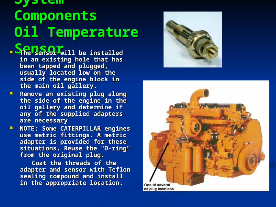
System System ComponentsComponentsOil Temperature Oil Temperature SensorSensor The sensor will be installed in The sensor will be installed in
an existing hole that has been an existing hole that has been tapped and plugged, usually tapped and plugged, usually located low on the side of the located low on the side of the engine block in the main oil engine block in the main oil gallery.gallery.
Remove an existing plug along Remove an existing plug along the side of the engine in the oil the side of the engine in the oil gallery and determine if any of gallery and determine if any of the supplied adapters are the supplied adapters are necessarynecessary
NOTE: Some CATERPILLAR NOTE: Some CATERPILLAR engines use metric fittings. A engines use metric fittings. A metric adapter is provided for metric adapter is provided for these situations. Reuse the "O-these situations. Reuse the "O-ring" from the original plug. ring" from the original plug.
Coat the threads of the adapter Coat the threads of the adapter and sensor with Teflon sealing and sensor with Teflon sealing compound and install in the compound and install in the appropriate location. appropriate location.

System System ComponentsComponents
Park Brake Park Brake SwitchSwitch
This switch is used to confirm This switch is used to confirm that the parking brakes have that the parking brakes have been applied on the tractor.been applied on the tractor.
Suggested Location Suggested Location The PARKING BRAKE The PARKING BRAKE
SWITCH must be installed in SWITCH must be installed in an air line, or in an available an air line, or in an available port, on the park brake valve port, on the park brake valve body. Must have POSITIVE body. Must have POSITIVE AIR PRESSURE with the AIR PRESSURE with the parking brakes released and parking brakes released and NO AIR PRESSURE when the NO AIR PRESSURE when the parking brake is applied. parking brake is applied.
Step 1 Step 1 Remove the instrument Remove the instrument
panel in the cab and locate panel in the cab and locate the park brake air line, that the park brake air line, that has “ 0” psi air with brake has “ 0” psi air with brake set & positive air pressure set & positive air pressure when the parking brake has when the parking brake has been released. been released.

System ComponentsSystem ComponentsPark Brake Switch cont.Park Brake Switch cont.
Step 2 Step 2 Splice the air Splice the air
line, then install line, then install the brass tee and the brass tee and PARKING BRAKE PARKING BRAKE SWITCH using SWITCH using the compression the compression fittings and fittings and insertsinserts..NOTE: Always use the metal inserts with the compression fittings on plastic air lines. Use sealant on pipe thread fittings. DO NOT OVER-TIGHTEN ferrules and nuts on plastic tubing.

System ComponentsSystem ComponentsPark Brake Switch cont.Park Brake Switch cont.
Step 3 Step 3
Connect the Connect the tan wires to tan wires to each terminal of each terminal of the switch. This the switch. This connection is connection is not polarity not polarity conscious.conscious.

System System ComponentsComponents
Hood Tilt Hood Tilt SwitchSwitch
The tilt switch senses The tilt switch senses when a conventional when a conventional tractor's hood is tractor's hood is opened or when a cab opened or when a cab over cab is tilted.over cab is tilted.
This switch should be This switch should be mounted to a vertical mounted to a vertical surface, when the surface, when the hood or cab is in the hood or cab is in the closed or down closed or down position. It should be position. It should be installed so that when installed so that when hood or cab are open hood or cab are open the TILT SW is open. the TILT SW is open. With hood or cab With hood or cab closed the TILT SW is closed the TILT SW is closed. The switch closed. The switch when tipped to about when tipped to about 50% of open, causes 50% of open, causes the circuit to open. the circuit to open.

System System ComponentsComponents
Hood Tilt Switch Hood Tilt Switch cont.cont.
Suggested Locations For Mounting SwitchSuggested Locations For Mounting Switch
Mount the TILT SWITCH to the vehicle in such a manner that the switch Mount the TILT SWITCH to the vehicle in such a manner that the switch will not be knocked out of adjustment easily. will not be knocked out of adjustment easily.
Conventional Tractors - Mount on the hood out of the way of wheel Conventional Tractors - Mount on the hood out of the way of wheel splash that results from rain and snow or ice accumulation. Be careful splash that results from rain and snow or ice accumulation. Be careful to protect the wires from damage as the hood is tilted. A recommended to protect the wires from damage as the hood is tilted. A recommended location is the back of the headlight assembly.location is the back of the headlight assembly.
Cab over Tractors - Behind the dash or in the console.Cab over Tractors - Behind the dash or in the console.
NOTE: The switch should be closed when the cab or hood is down and open when the cab or hood is up.
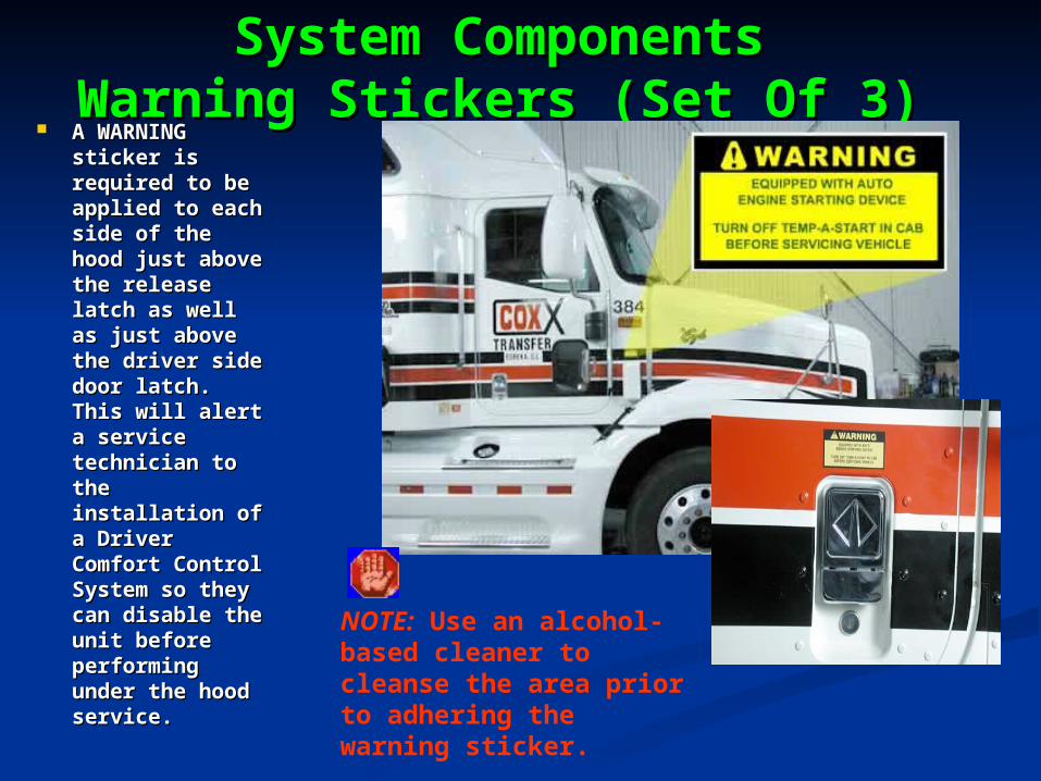
System ComponentsSystem ComponentsWarning Stickers (Set Of 3)Warning Stickers (Set Of 3)
A WARNING A WARNING sticker is sticker is required to be required to be applied to each applied to each side of the side of the hood just above hood just above the release the release latch as well as latch as well as just above the just above the driver side driver side door latch. door latch. This will alert a This will alert a service service technician to technician to the installation the installation of a Driver of a Driver Comfort Comfort Control System Control System so they can so they can disable the disable the unit before unit before performing performing under the hood under the hood service.service.
NOTE: Use an alcohol-based cleaner to cleanse the area prior to adhering the warning sticker.

Common Symptoms TAS Will Not Common Symptoms TAS Will Not Activate & Possible FixesActivate & Possible Fixes
1. TAS will not go active, led stays red.
• Possible Tilt Switch circuit open
• Possible Park Brake circuit open
• Possible RPM signal loss
• Quick Tests
a. With test light check for power at Park Brake wires on switch, or at back of TAS main control center. ( Wire color on module side are tan / tan & white ) Engine Off. If No power check Tilt switch wires at back of TAS control center ( wire color gray/ white & gray) If you find no power, find & repair open circuit. If power found, go to test two.
b. Start engine. At back of control center, check orange / white wire, for RPM input signal. With a digital volt meter on 10 volt ac scale you should read at least 3 volts AC. Yes: Replace TAS control center. No: find & repair lost RPM sig.

page 31


Copyright 2013, Temp-A-StartCopyright 2013, Temp-A-Start
The information in the Power Point Presentation is The information in the Power Point Presentation is not all inclusive and cannot take into account all the not all inclusive and cannot take into account all the unique situations. Note that some illustrations are unique situations. Note that some illustrations are typical and may not reflect the exact arrangement of typical and may not reflect the exact arrangement of every component installed on a specific chassis.every component installed on a specific chassis.
The information, specifications, and illustrations in The information, specifications, and illustrations in this presentation are based on information that was this presentation are based on information that was current at the time of publication.current at the time of publication.
No part of this presentation may be reproduced in No part of this presentation may be reproduced in any way without prior written consent of Temp-A-any way without prior written consent of Temp-A-StartStart..