Tema2 esfuerzos
47
BIBLIOGRAFIA • Bernard J. Hamrock, Elementos de máquinas. Ed. Mc Graw Hill. • Robert L. Norton, Diseño de máquinas. Ed. Prentice Hall. • Shigley, Diseño en Ingeniería Mecánica, Ed. Mc Graw-Hill
-
Upload
annaly -
Category
Automotive
-
view
196 -
download
2
Transcript of Tema2 esfuerzos
BIBLIOGRAFIA
• Bernard J. Hamrock, Elementos de máquinas. Ed. Mc Graw Hill.
• Robert L. Norton, Diseño de máquinas. Ed. Prentice Hall.
• Shigley, Diseño en Ingeniería Mecánica, Ed. Mc Graw-Hill
Load, Stress and Strain
When I am working on a problem, I never thinkabout beauty. I only think of how to solve theproblem. But when I have finished, if the solutionis not beautiful, I know it is wrong.
Richard Buckminster Fuller
Image: A dragline lifts a large load in a mining operation.

A Simple Crane
Figure 2.1 A simple crane and forces acting on it. (a) Assembly drawing; (b) free-body diagram of forces acting on the beam.
text reference: Figure 2.1, page 30

Supports and Reactions
Table 2.1: Four types of support with their corresponding reactions.
text reference: Table 2.1, page 35

Ladder Free Body Diagram
Figure 2.5: Ladder having contact with the house and the ground while having a painter on the ladder. Used in Example 2.4. The ladder length is l.
text reference: Figure 2.5, page 36

Load Classification
text reference: Figure 2.2, page 31
Figure 2.2 Load classified as to location and method of application. (a) Normal, tensile (b) normal, compressive; (c) shear; (d) bending; (e) torsion; (f) combined
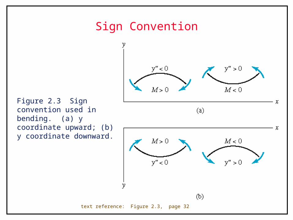
Sign Convention
Figure 2.3 Sign convention used in bending. (a) y coordinate upward; (b) y coordinate downward.
text reference: Figure 2.3, page 32
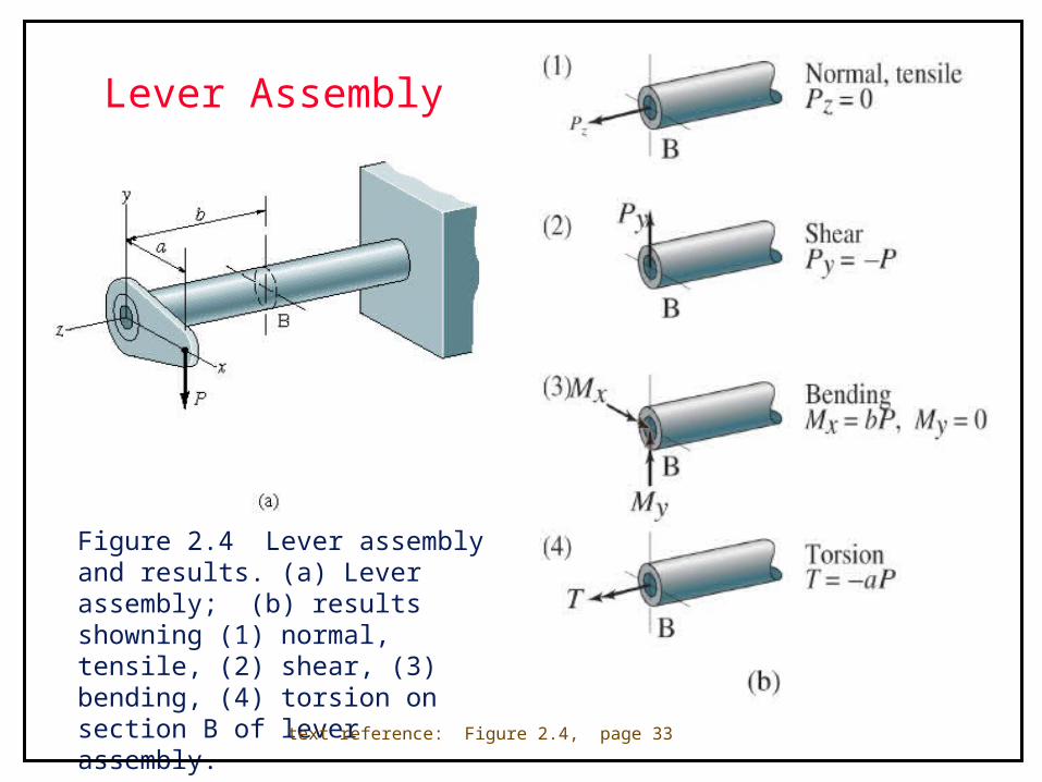
Lever Assembly
Figure 2.4 Lever assembly and results. (a) Lever assembly; (b) results showning (1) normal, tensile, (2) shear, (3) bending, (4) torsion on section B of lever assembly.
text reference: Figure 2.4, page 33
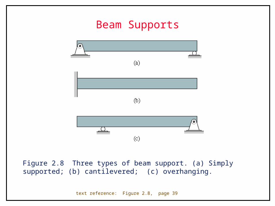
Beam Supports
Figure 2.8 Three types of beam support. (a) Simply supported; (b) cantilevered; (c) overhanging.
text reference: Figure 2.8, page 39
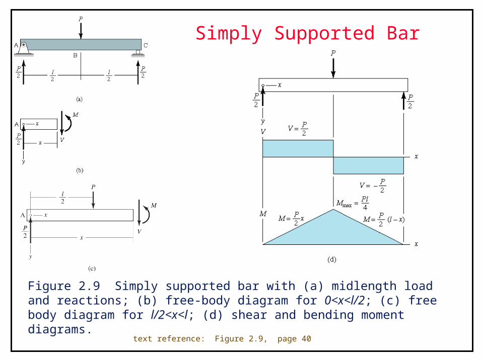
Simply Supported Bar
Figure 2.9 Simply supported bar with (a) midlength load and reactions; (b) free-body diagram for 0<x<l/2; (c) free body diagram for l/2<x<l; (d) shear and bending moment diagrams.
text reference: Figure 2.9, page 40
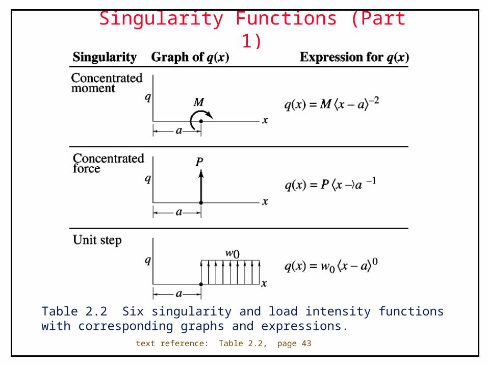
Singularity Functions (Part 1)
Table 2.2 Six singularity and load intensity functions with corresponding graphs and expressions.
text reference: Table 2.2, page 43

Singularity Functions (Part 2)
Table 2.2 Six singularity and load intensity functions with corresponding graphs and expressions.
text reference: Table 2.2, page 43
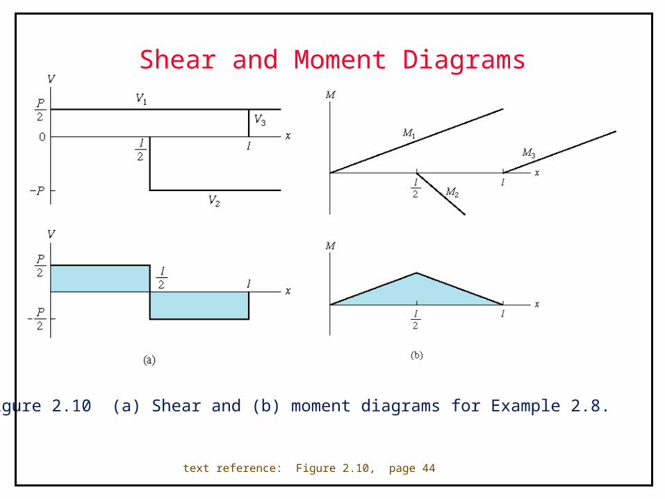
Shear and Moment Diagrams
Figure 2.10 (a) Shear and (b) moment diagrams for Example 2.8.
text reference: Figure 2.10, page 44
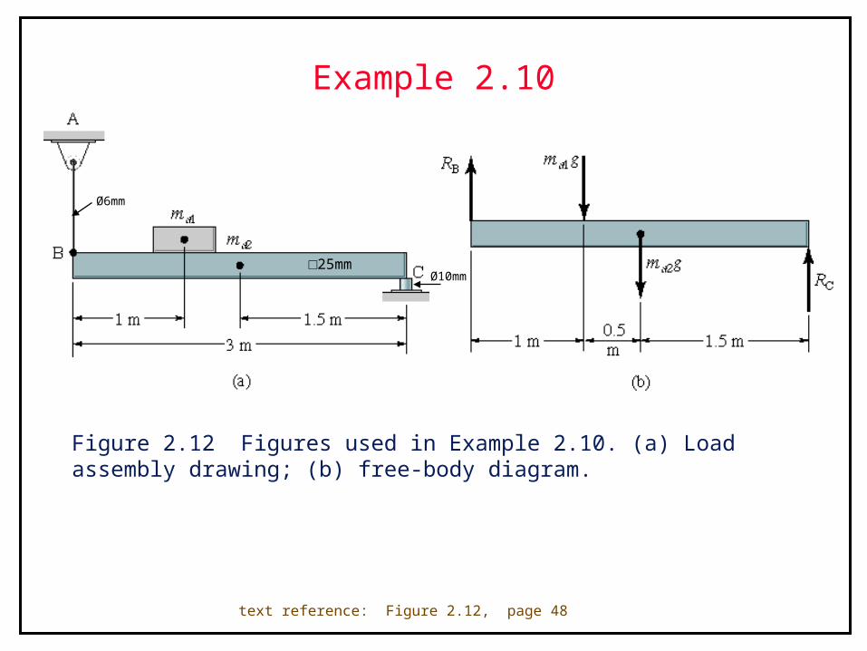
Example 2.10
Figure 2.12 Figures used in Example 2.10. (a) Load assembly drawing; (b) free-body diagram.
text reference: Figure 2.12, page 48
Ø10mm
Ø6mm
□25mm
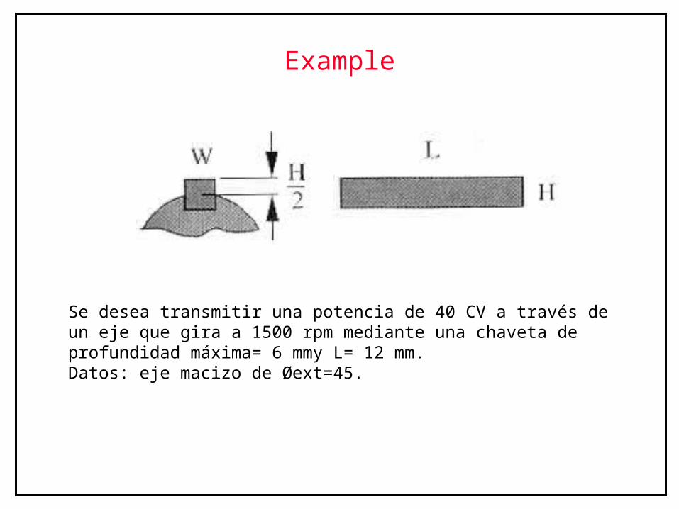
Example
Se desea transmitir una potencia de 40 CV a través de un eje que gira a 1500 rpm mediante una chaveta de profundidad máxima= 6 mmy L= 12 mm.Datos: eje macizo de Øext=45.
Example
kgrMtFtrFtMt
cmkgn
CVMt
85025,25,1912
5,19121500
407172071720
2
2
5,11802,16,0
850
2
3,5902,12,1
850
cmkg
LhFt
Ap
Ft
cmkg
LW
Ft
Ac
Ft
d
d
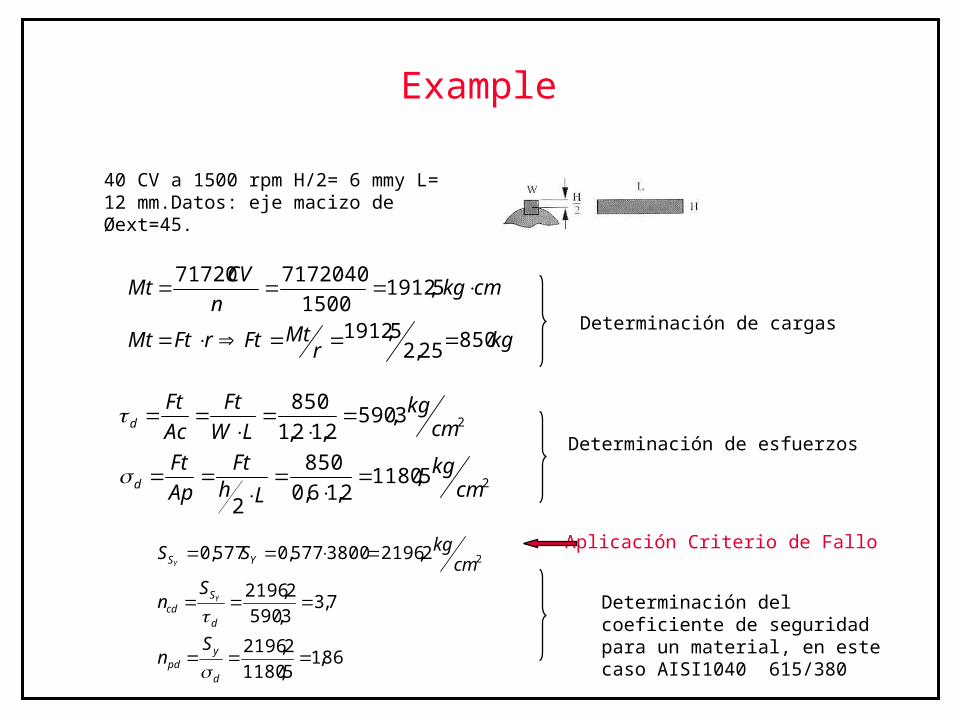
40 CV a 1500 rpm H/2= 6 mmy L= 12 mm.Datos: eje macizo de Øext=45.
86,15,1180
2,2196
7,33,590
2,2196
2,21963800577,0577,0 2
d
ypd
d
Scd
YS
Sn
Sn
cmkgSS
Y
Y
Determinación del coeficiente de seguridad para un material, en este caso AISI1040 615/380
Determinación de cargas
Determinación de esfuerzos
Aplicación Criterio de Fallo
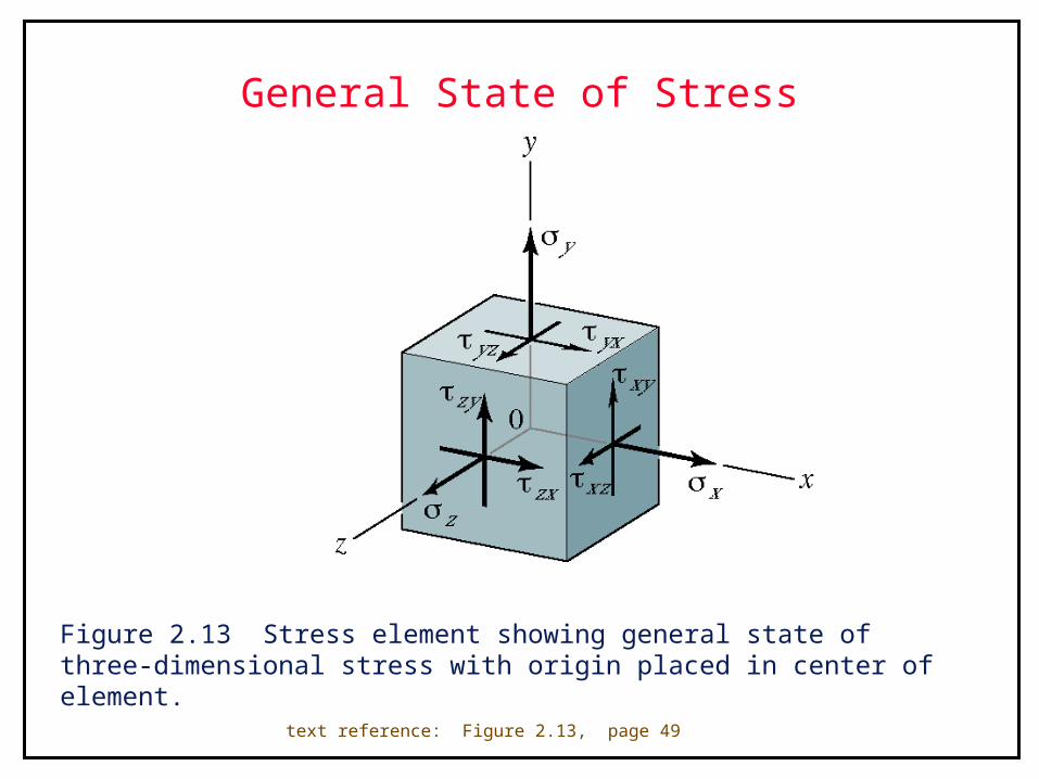
General State of Stress
Figure 2.13 Stress element showing general state of three-dimensional stress with origin placed in center of element.
text reference: Figure 2.13, page 49
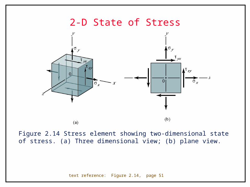
2-D State of Stress
Figure 2.14 Stress element showing two-dimensional state of stress. (a) Three dimensional view; (b) plane view.
text reference: Figure 2.14, page 51
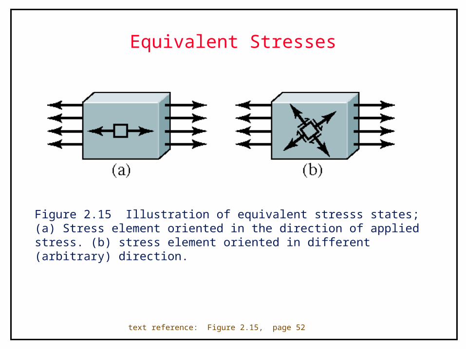
Equivalent Stresses
Figure 2.15 Illustration of equivalent stresss states; (a) Stress element oriented in the direction of applied stress. (b) stress element oriented in different (arbitrary) direction.
text reference: Figure 2.15, page 52
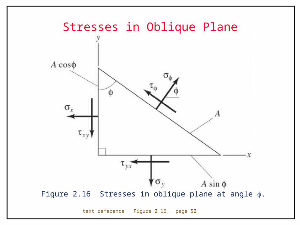
Stresses in Oblique Plane
Figure 2.16 Stresses in oblique plane at angle .
text reference: Figure 2.16, page 52
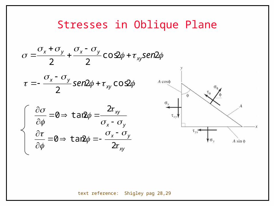
Stresses in Oblique Plane
22cos22
senxyyxyx
2cos22 xy
yx sen
2cos22 xy
yx sen
text reference: Shigley pag 28,29
yx
xy
2
2tan0
xy
yx
22tan0
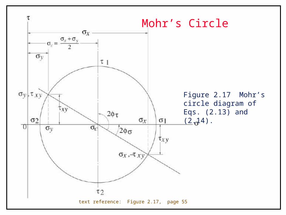
Mohr’s Circle
Figure 2.17 Mohr’s circle diagram of Eqs. (2.13) and (2.14).
text reference: Figure 2.17, page 55
Mohr’s Circle Example
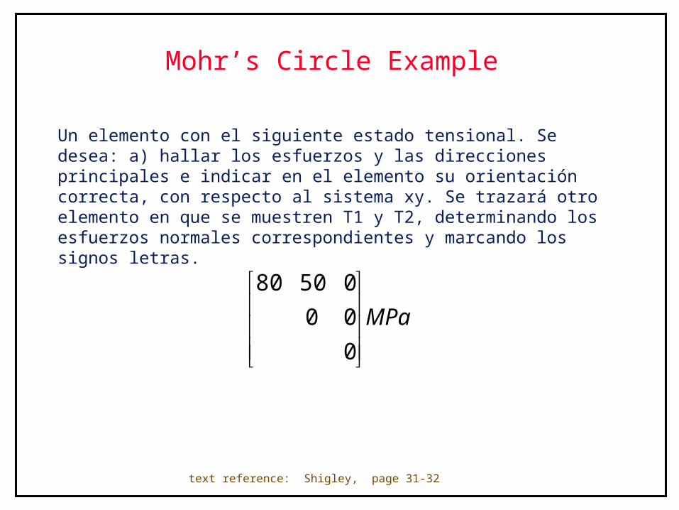
Un elemento con el siguiente estado tensional. Se desea: a) hallar los esfuerzos y las direcciones principales e indicar en el elemento su orientación correcta, con respecto al sistema xy. Se trazará otro elemento en que se muestren T1 y T2, determinando los esfuerzos normales correspondientes y marcando los signos letras.
text reference: Shigley, page 31-32
MPa
0
00
05080
Results from Example
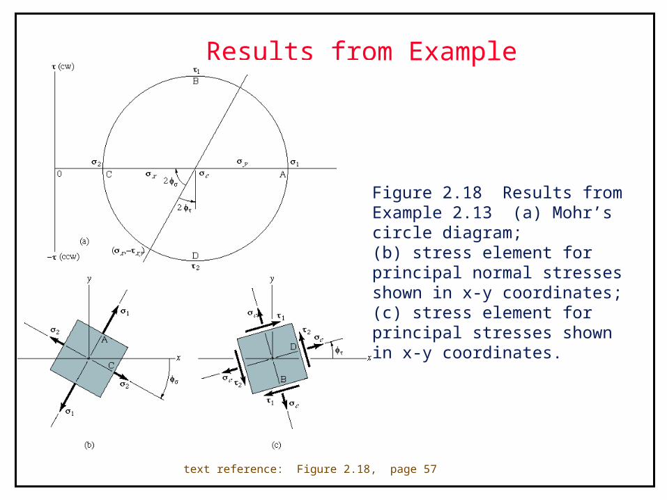
Figure 2.18 Results from Example 2.13 (a) Mohr’s circle diagram; (b) stress element for principal normal stresses shown in x-y coordinates; (c) stress element for principal stresses shown in x-y coordinates.
text reference: Figure 2.18, page 57
Mohr’s Circle for Triaxial Stress State
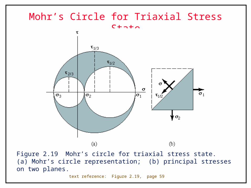
Figure 2.19 Mohr’s circle for triaxial stress state. (a) Mohr’s circle representation; (b) principal stresses on two planes.
text reference: Figure 2.19, page 59
Example 3.5
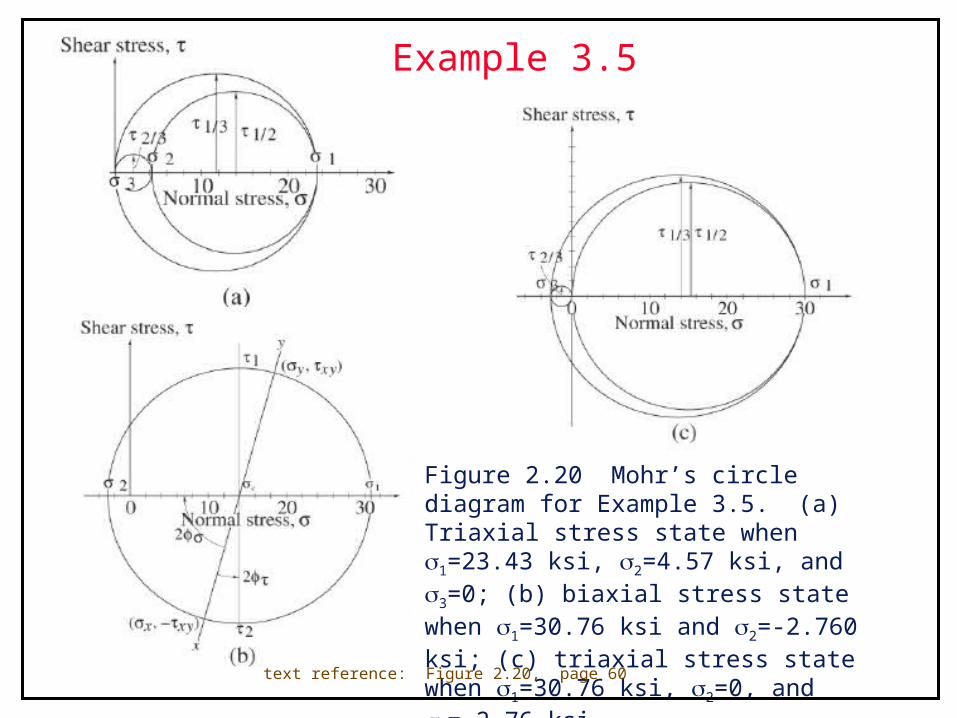
Figure 2.20 Mohr’s circle diagram for Example 3.5. (a) Triaxial stress state when 1=23.43 ksi, 2=4.57 ksi, and 3=0; (b) biaxial stress state when 1=30.76 ksi and 2=-2.760 ksi; (c) triaxial stress state when 1=30.76 ksi, 2=0, and 3=-2.76 ksi.
text reference: Figure 2.20, page 60
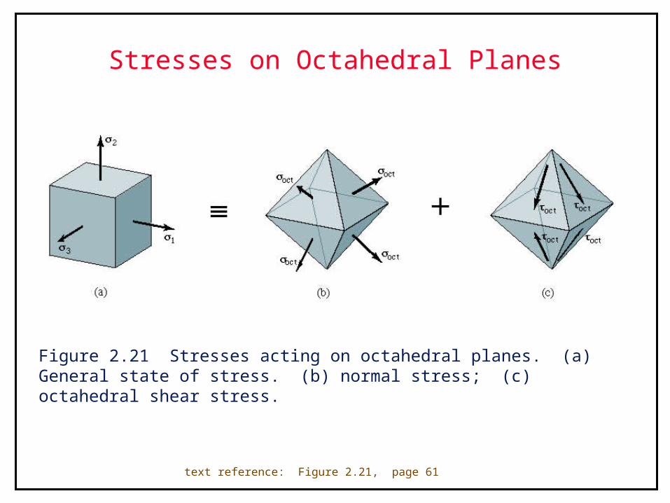
Stresses on Octahedral Planes
Figure 2.21 Stresses acting on octahedral planes. (a) General state of stress. (b) normal stress; (c) octahedral shear stress.
text reference: Figure 2.21, page 61
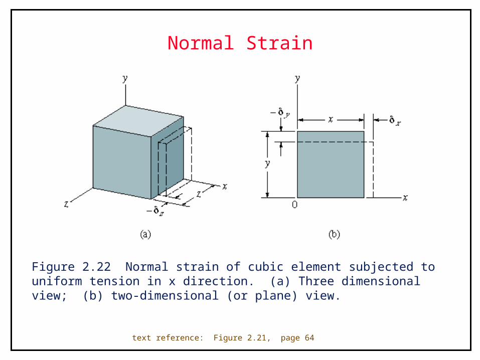
Normal Strain
Figure 2.22 Normal strain of cubic element subjected to uniform tension in x direction. (a) Three dimensional view; (b) two-dimensional (or plane) view.
text reference: Figure 2.21, page 64
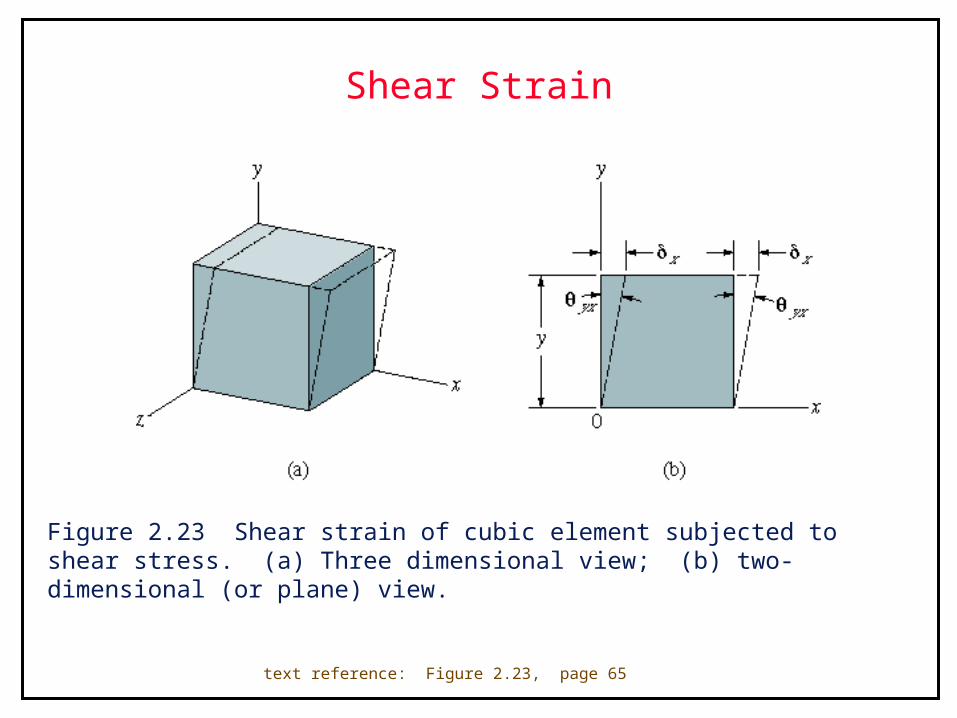
Shear Strain
Figure 2.23 Shear strain of cubic element subjected to shear stress. (a) Three dimensional view; (b) two-dimensional (or plane) view.
text reference: Figure 2.23, page 65
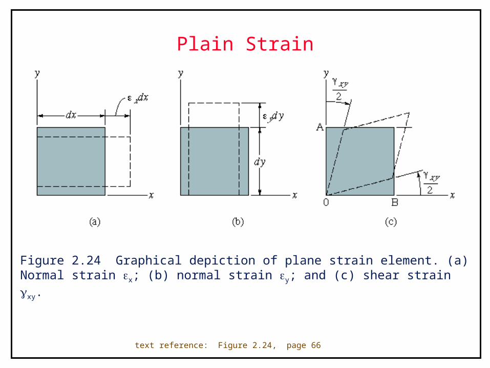
Plain Strain
Figure 2.24 Graphical depiction of plane strain element. (a) Normal strain x; (b) normal strain y; and (c) shear strain xy.
text reference: Figure 2.24, page 66
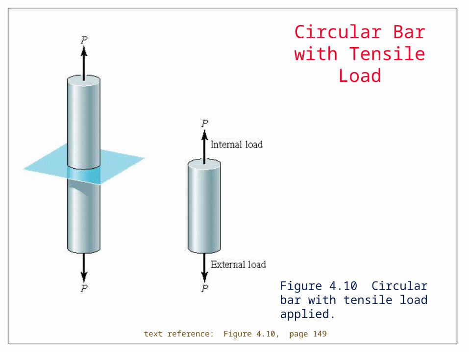
Circular Bar with Tensile Load
Figure 4.10 Circular bar with tensile load applied.
text reference: Figure 4.10, page 149
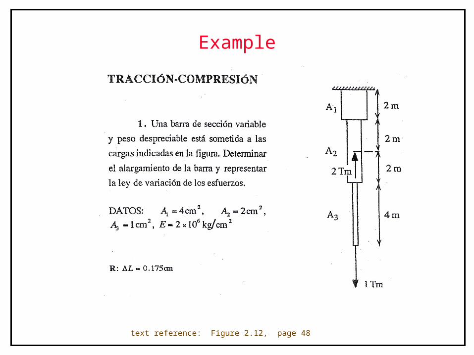
Example
text reference: Figure 2.12, page 48
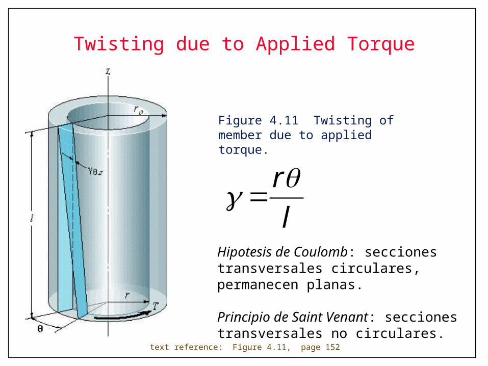
Twisting due to Applied Torque
Figure 4.11 Twisting of member due to applied torque.
text reference: Figure 4.11, page 152
l
r
Hipotesis de Coulomb: secciones transversales circulares, permanecen planas.
Principio de Saint Venant: secciones transversales no circulares.
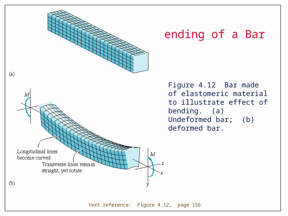
Bending of a Bar
Figure 4.12 Bar made of elastomeric material to illustrate effect of bending. (a) Undeformed bar; (b) deformed bar.
text reference: Figure 4.12, page 156
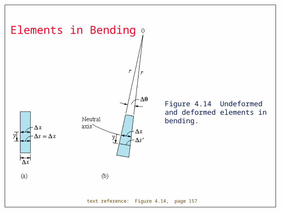
Figure 4.14 Undeformed and deformed elements in bending.
text reference: Figure 4.14, page 157
Elements in Bending
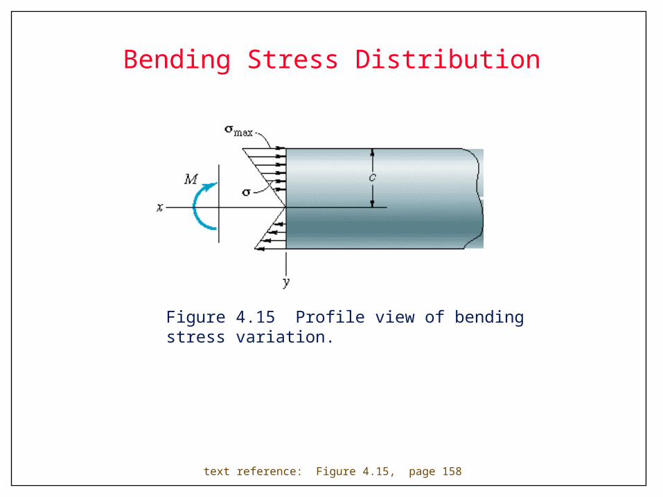
Bending Stress Distribution
Figure 4.15 Profile view of bending stress variation.
text reference: Figure 4.15, page 158
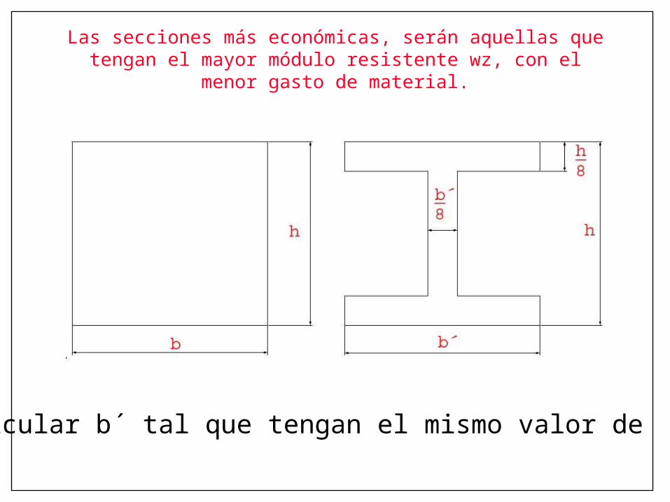
Las secciones más económicas, serán aquellas que tengan el mayor módulo resistente wz, con el menor gasto de material.
¿Calcular b´ tal que tengan el mismo valor de Wx?
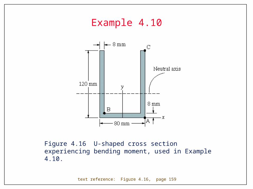
Example 4.10
Figure 4.16 U-shaped cross section experiencing bending moment, used in Example 4.10.
text reference: Figure 4.16, page 159
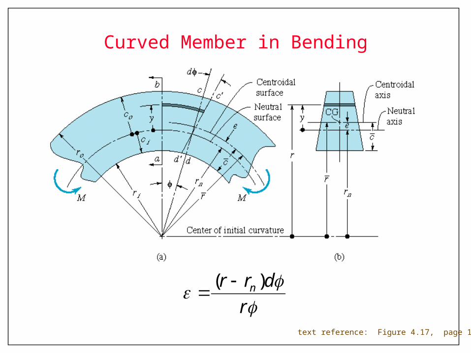
Curved Member in Bending
text reference: Figure 4.17, page 161
r
drr n )(
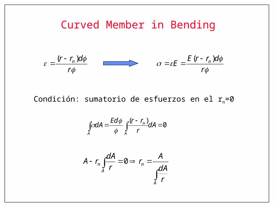
Curved Member in Bending
0)(
dAr
rrEddA
A
n
A
r
drrEE n )(
r
drr n )(
Condición: sumatorio de esfuerzos en el rn=0
A
n
A
n
rdA
Ar
r
dArA 0
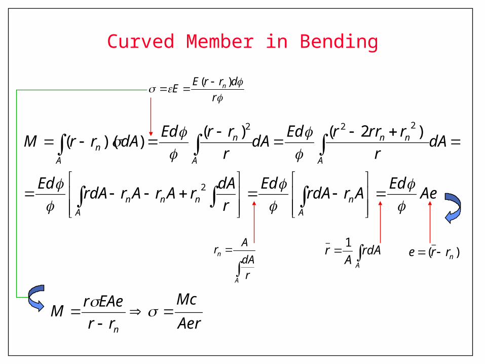
Curved Member in Bending
dArA
rA
1_
r
drrEE n )(
)(_
nrre
A
n
rdA
Ar
Aer
Mc
rr
EAerM
n
AeEd
ArrdAEd
r
dArArArrdA
Ed
dAr
rrrrEddA
r
rrEddArrM
A
n
A
nnn
A
nn
A
n
A
n
2
222 )2()())((
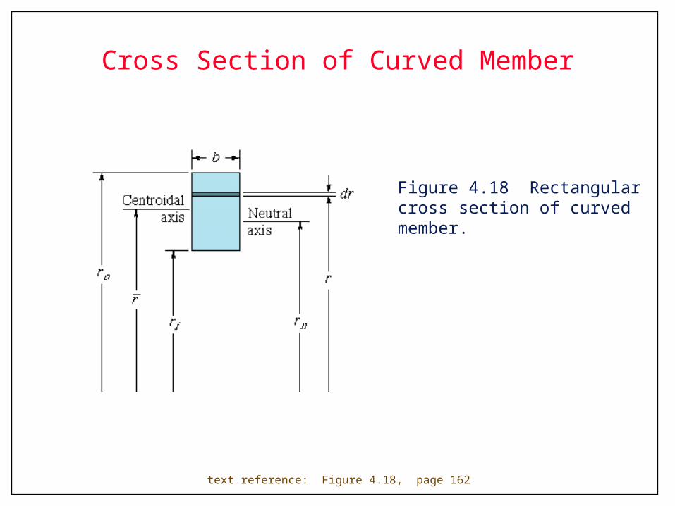
Cross Section of Curved Member
Figure 4.18 Rectangular cross section of curved member.
text reference: Figure 4.18, page 162
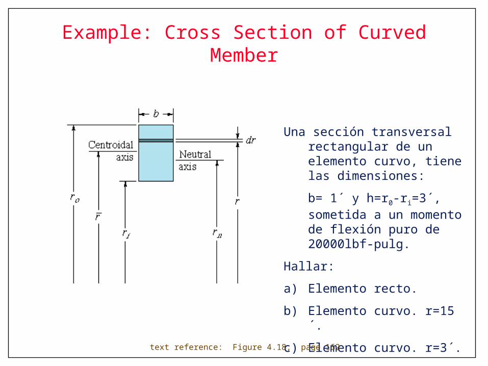
Example: Cross Section of Curved Member
Una sección transversal rectangular de un elemento curvo, tiene las dimensiones:
b= 1´ y h=r0-ri=3´, sometida a un momento de flexión puro de 20000lbf-pulg.
Hallar:
a) Elemento recto.
b) Elemento curvo. r=15´.
c) Elemento curvo. r=3´.
text reference: Figure 4.18, page 162
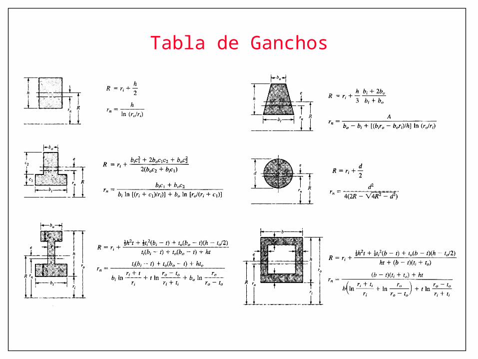
Tabla de Ganchos
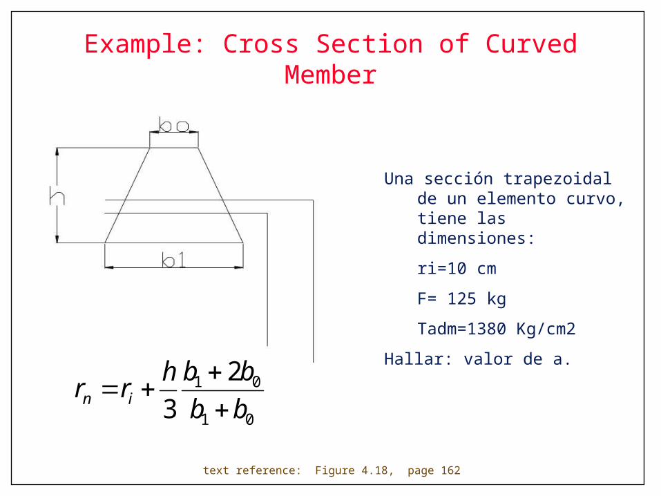
Example: Cross Section of Curved Member
Una sección trapezoidal de un elemento curvo, tiene las dimensiones:
ri=10 cm
F= 125 kg
Tadm=1380 Kg/cm2
Hallar: valor de a.
text reference: Figure 4.18, page 162
01
01 2
3 bb
bbhrr in

Development of Transverse Shear
Figure 4.19 How transverse shear is developed.
text reference: Figure 4.19, page 165

Maximum Shear Stress
Table 4.3 Maximum shear stress for different beam cross sections.
text reference: Table 4.3, page 168