TELESCOPIC CRANE - Manitex SERIES TELESCOPIC CRANE 6 Data published herein is intended as a guide...
28
-
Upload
duongnguyet -
Category
Documents
-
view
218 -
download
0
Transcript of TELESCOPIC CRANE - Manitex SERIES TELESCOPIC CRANE 6 Data published herein is intended as a guide...
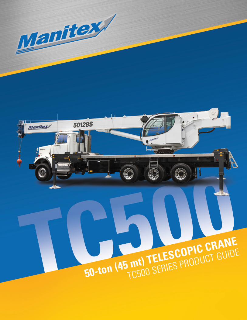
TC500 SERIES TELESCOPIC CRANE
2
CONTENTSCrane Features ................................................................................................................................................................................4
5096S Chassis Data - S Models .................................................................................................................................................... 5
50110S & SHL Chassis Data .......................................................................................................................................................... 6
50128S & SHL Chassis Data .......................................................................................................................................................... 7
50155S & SHL Chassis Data .......................................................................................................................................................... 8
Outrigger Extension......................................................................................................................................................................... 9
Sub Frame ....................................................................................................................................................................................... 9
Electrical System ............................................................................................................................................................................ 9
5096S Load Chart: Main Boom and Jib .........................................................................................................................................10
5096S Boom Diagram ...................................................................................................................................................................11
50110S Load Chart: Main Boom ....................................................................................................................................................12
50110S Boom Diagram .................................................................................................................................................................13
50110SHL Load Chart: Main Boom and Jib ...................................................................................................................................14
50110SHL Boom Diagram .............................................................................................................................................................15
50128S Load Chart: Main Boom and Jib .......................................................................................................................................16
50128S Boom Diagram .................................................................................................................................................................17
50128SHL Load Chart: Main Boom and Jib ...................................................................................................................................18
50128SHL Boom Diagram .............................................................................................................................................................19
50155S Load Chart: Main Boom and Jib .......................................................................................................................................20
50155S Boom Diagram .................................................................................................................................................................21
50155SHL Load Chart: Main Boom and Jib ...................................................................................................................................22
50155SHL Boom Diagram .............................................................................................................................................................23
Area of Operation ..........................................................................................................................................................................24
LMI Codes ......................................................................................................................................................................................24
Reeving Diagram ...........................................................................................................................................................................24
Technical Descriptions ..................................................................................................................................................................25
Options .................................................................................................................................................................................. 26 & 27
Effective Date: September 1, 2013This document is non-contractual. This document is supplied for reference use only. We are constantly making improvements to our products and reserve the right that specification, equipment, and prices are all subject to change without notice or obligation. The photographs, and /or images in this document are for illustrative purposes only and may include optional equipment and accessories and may not include all standard equipment. Refer to the appropriate Operator’s Manual and Load Charts for instructions on the proper use of this equipment to determine allowable crane lifting capacities, assembly and operating procedures.Failure to follow the appropriate operator’s manual or load chart(s) when using our equipment or to otherwise act irresponsibly may result in serious injury or death. The only warranty applicable to our equipment is the standard written warranty applicable to the particular product and sale. Manitex makes no other warranty, expressed or implied. Products and services listed may be trademarks, service marks or trade-names of Manitex International and /or its subsidiaries in the USA and other countries. All rights are reserved. Manitex® is a registered trademark of Manitex International, Inc. in the USA and many other countries.Copyright 2013 Manitex Inc. Manitex Inc, Georgetown Texas, 78626
/ / / / / / / / / / / / / / / / / / / / / / / / / / / / / / / / / / / / / / / / / / / / / / / / / / / / / / / / / / / / / / / / / / / / / / / / / / / / / / / / / / / / / / / / / / / / / / / / / / / / / / / / / / / / / / /
3
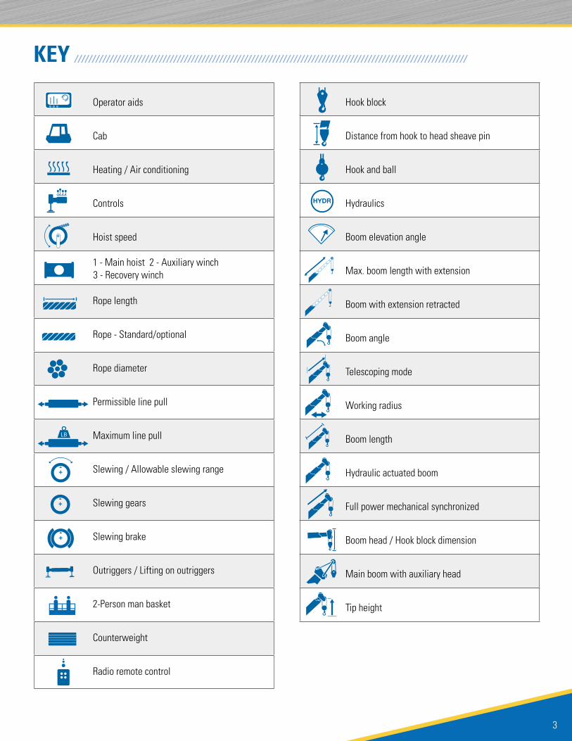
KEY
Operator aids
Cab
Heating / Air conditioning
Controls
Hoist speed
1 - Main hoist 2 - Auxiliary winch 3 - Recovery winch
Rope length
Rope - Standard/optional
Rope diameter
Permissible line pull
Maximum line pull
Slewing / Allowable slewing range
Slewing gears
Slewing brake
Outriggers / Lifting on outriggers
2-Person man basket
Counterweight
Radio remote control
Hook block
Distance from hook to head sheave pin
Hook and ball
Hydraulics
Boom elevation angle
Max. boom length with extension
Boom with extension retracted
Boom angle
Telescoping mode
Working radius
Boom length
Hydraulic actuated boom
Full power mechanical synchronized
Boom head / Hook block dimension
Main boom with auxiliary head
Tip height
/ / / / / / / / / / / / / / / / / / / / / / / / / / / / / / / / / / / / / / / / / / / / / / / / / / / / / / / / / / / / / / / / / / / / / / / / / / / / / / / / / / / / / / / / / / / / / / / / / / / / / / / / / / / / / / /

TC500 SERIES TELESCOPIC CRANE
4
THE TC500 SERIES TELESCOPIC CRANEVersatile. Affordable. User friendly.The TC500 series telescopic cranes are built to meet the wide-ranging needs of owner operators who may use it for residential construction one day and bridge work the next. No matter what the task, the 50-ton line of telescopic cranes is designed to get you to the job and on the job quickly. With it, you can:
• Travel to and between job sites at highway speed on a commercial chassis
• Set up quickly with radio outrigger controls
• Operate comfortably and confidently in its tiltable cab
Other features include:• 50-ton capacity @ 6 ft. radius
• 4 & 5-section proportional boom
• Optional telescopic jib
• 187 ft. maximum tip height (with optional telescopic jib)
• Tiltable cab
• Out-and-down outriggers
• Remote outrigger controls
RADIO OUTRIGGER CONTROLSOperate the outriggers remotely, with a clear view of the machine, using radio outrigger controls we call ROC Solid.
TWO-SPEED PLANETARY HOISTIncrease productivity and minimize downtime. The two-speed planetary hoist lets you change line speed on the fly and minimize rope stacking.
REMOTE WINCH CONTROLLower and raise the hook block quickly. With remote winch control on the TC500 series, the winch can be operated from any location. (OPTIONAL)
/ / / / / / / / / / / / / / / / / / / / / / / / / / / / / / / / / / / / / / / / / / / / / / / / / / / / / / / / / / / / / / / / / / / / / / / / / /
/ / / / / / / / / / / / / / / / / / / / / / / / / / / / / / / / / / / / / / / / / / / / / / / / / / / / / / / / / / / / / / / / / / / / / / / / / / / / / / / / / / / / / / / / / / / / / / / / / / / / / / / / / / / / / / / /
INCREASE PROFITABILITYThe versatile TC500 series is designed to help both owners and operators make the most of their investment.
• Travel to and between jobs at highway speed.
• Minimize maintenance costs with replaceable, self-lubricating boom slider pads and sealed, multi-disc wet brakes on the hoist and swing system.
• Minimize repair costs with first-up auto retract feature of front bumper stabilizer that prevents drive-away damage.
Operator cab tilts from 0º to 20° for a comfortable, clear view of the load.

5
5096S CHASSIS DATA / / / / / / / / / / / / / / / / / / / / / / / / / / / / / / / / / / / / / / / / / / / / / / / / / / / / / / / / / / / / / / / / / / /
Data published herein is intended as a guide only. Crane operation is subject to machine specific load charts and information.
CRANE WEIGHT
TRUCK AXLE WEIGHTCHASSIS DATA5096S
Min. truck axle W - Front** 9,100 lbs. (4,127 kg)
Min. truck axle W - Rear** 11,150 lbs. (5,057 kg)
Nominal Frame W 34 in. (864 mm)
Model 5096S
Frame section modulus at 180/360º area of operation*
27.0 in3 120,000 psi 827,371 kPa
5096S
Crane 35,755 lbs. (16,218 kg)
Jib fixed 1,510 lbs. (685 kg)
Jib telescopic 1,870 lbs. (848 kg)
Aluminum Platform 621 lbs. (282 kg)
Notes: Additional axles required for federal bridge legal configuration - consult Manitex. Manitex highly recommends the addition of a front stabilizer and it may be required on some installations - consult Manitex.
* Frame selection modulus at 360º area of operation requires front bumper stabilizer. ** Minimum chassis weight is required to meet 85% stability requirements. Chassis data is general - not for engineering. Some dimensions depend on truck selection.
Auxiliary Sheave Head
Dimensions
TC500 SERIES TELESCOPIC CRANE
6
Data published herein is intended as a guide only. Crane operation is subject to machine specific load charts and information.
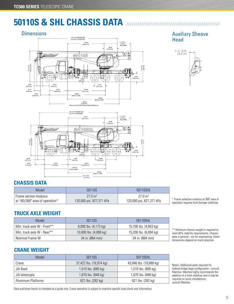
50110S & SHL CHASSIS DATA / / / / / / / / / / / / / / / / / / / / / / / / / / / / / / / / / / / / / / / / / / / / / / / / / / /
CRANE WEIGHT
TRUCK AXLE WEIGHTModel 50110S 50110SHL
Min. truck axle W - Front** 9,000 lbs. (4,173 kg) 10,700 lbs. (4,853 kg)
Min. truck axle W - Rear** 10,600 lbs. (4,808 kg) 15,200 lbs. (6,894 kg)
Nominal Frame W 34 in. (864 mm) 34 in. (864 mm)
Model 50110S 50110SHL
Crane 37,422 lbs. (16,974 kg) 43,846 lbs. (19,888 kg)
Jib fixed 1,510 lbs. (685 kg) 1,510 lbs. (685 kg)
Jib telescopic 1,870 lbs. (848 kg) 1,870 lbs. (848 kg)
Aluminum Platforms 621 lbs. (282 kg) 621 lbs. (282 kg)
Notes: Additional axles required for federal bridge legal configuration - consult Manitex. Manitex highly recommends the addition of a front stabilizer and it may be required on some installations - consult Manitex.
** Minimum chassis weight is required to meet 85% stability requirements. Chassis data is general - not for engineering. Some dimensions depend on truck selection.
Auxiliary Sheave Head
Dimensions
Model 50110S 50110SHL
Frame section modulus at 180/360º area of operation*
27.0 in3 120,000 psi, 827,371 kPa
27.0 in3 120,000 psi, 827,371 kPa * Frame selection modulus at 360º area of
operation requires front bumper stabilizer.
CHASSIS DATA
7
Data published herein is intended as a guide only. Crane operation is subject to machine specific load charts and information.
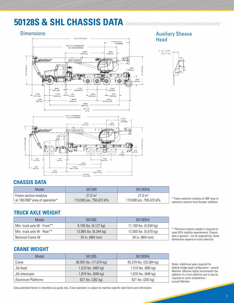
50128S & SHL CHASSIS DATA / / / / / / / / / / / / / / / / / / / / / / / / / / / / / / / / / / / / / / / / / / / / / / / / / / / /
CRANE WEIGHT
TRUCK AXLE WEIGHTModel 50128S 50128SHL
Min. truck axle W - Front** 9,100 lbs. (4,127 kg) 11,100 lbs. (5,034 kg)
Min. truck axle W - Rear** 13,985 lbs. (6,344 kg) 12,500 lbs. (5,670 kg)
Nominal Frame W 34 in. (864 mm) 34 in. (864 mm)
Model 50128S 50128SHL
Crane 38,955 lbs. (17,670 kg) 45,379 lbs. (20,584 kg)
Jib fixed 1,510 lbs. (685 kg) 1,510 lbs. (685 kg)
Jib telescopic 1,870 lbs. (848 kg) 1,870 lbs. (848 kg)
Aluminum Platforms 621 lbs. (282 kg) 621 lbs. (282 kg)
Notes: Additional axles required for federal bridge legal configuration - consult Manitex. Manitex highly recommends the addition of a front stabilizer and it may be required on some installations - consult Manitex.
** Minimum chassis weight is required to meet 85% stability requirements. Chassis data is general - not for engineering. Some dimensions depend on truck selection.
Auxiliary Sheave Head
Dimensions
CHASSIS DATAModel 50128S 50128SHL
Frame section modulus at 180/360º area of operation*
27.0 in3 110,000 psi, 758,423 kPa
27.0 in3 110,000 psi, 758,423 kPa * Frame selection modulus at 360º area of
operation requires front bumper stabilizer.

TC500 SERIES TELESCOPIC CRANE
8
Data published herein is intended as a guide only. Crane operation is subject to machine specific load charts and information.
50155S & SHL CHASSIS DATA / / / / / / / / / / / / / / / / / / / / / / / / / / / / / / / / / / / / / / / / / / / / / / / / / / / /
Auxiliary Sheave Head
Dimensions
CRANE WEIGHT
TRUCK AXLE WEIGHTModel 50155S 50155SHL
Min. truck axle W - Front** 10,750 lbs. (4876 kg) 9,500 lbs. (4,309 kg)
Min. truck axle W - Rear** 12,300 lbs. (5,579 kg) 13,400 lbs. (6,078 kg)
Nominal Frame W 34 in. (864 mm) 34 in. (864 mm)
Model 50155S 50155SHL
Crane 39,175 lbs. (17,796 kg) 45,605 lbs. (20,686 kg)
Jib fixed 1,510 lbs. (685 kg) 1,510 lbs. (685 kg)
Jib telescopic N/A N/A
Aluminum Platforms 621 lbs. (282 kg) 621 lbs. (282 kg)
Notes: Additional axles required for federal bridge legal configuration - consult Manitex. Manitex highly recommends the addition of a front stabilizer and it may be required on some installations - consult Manitex.
** Minimum chassis weight is required to meet 85% stability requirements. Chassis data is general - not for engineering. Some dimensions depend on truck selection.
CHASSIS DATAModel 50155S 50155SHL
Frame section modulus at 180/360º area of operation*
27.0 in3 110,000 psi, 758,423 kPa
27.0 in3 110,000 psi, 758,423 kPa * Frame selection modulus at 360º area of
operation requires front bumper stabilizer.
9
Data published herein is intended as a guide only. Crane operation is subject to machine specific load charts and information.
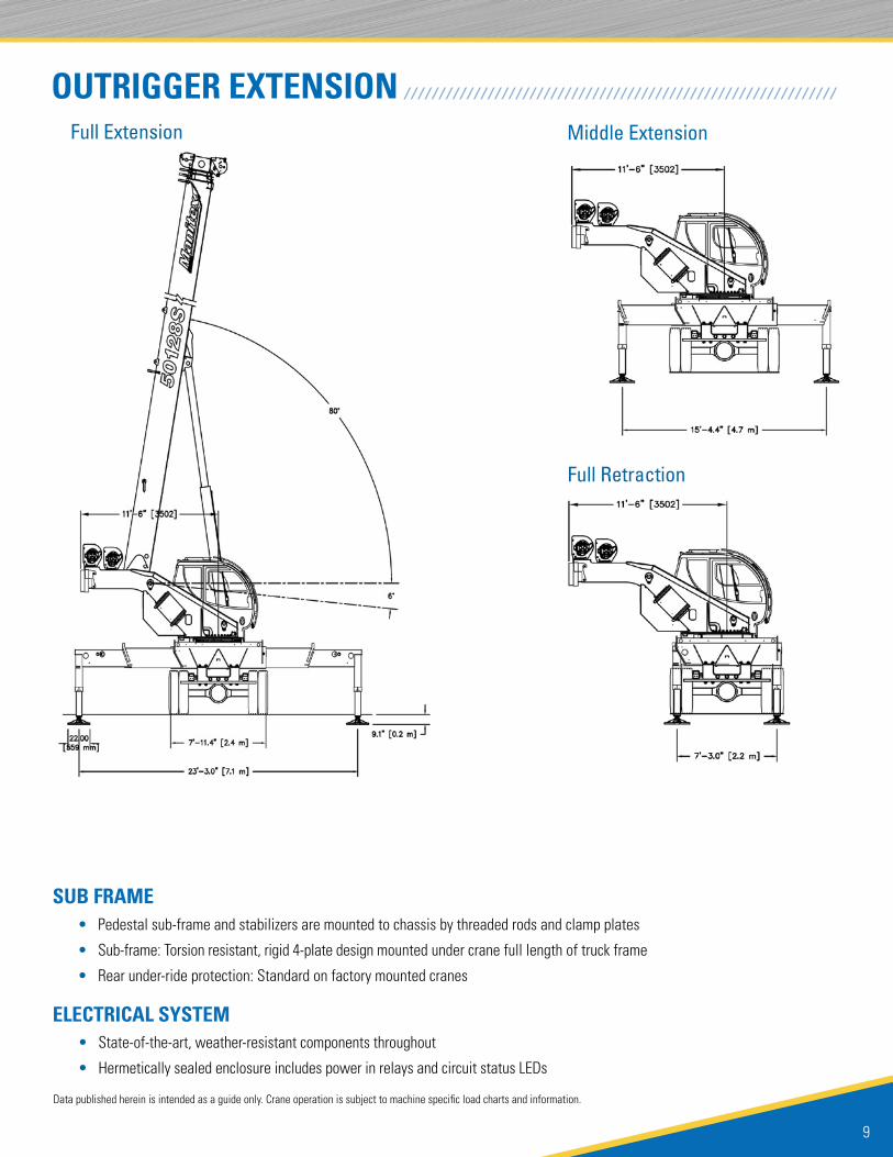
OUTRIGGER EXTENSIONFull Extension
Full Retraction
Middle Extension
/ / / / / / / / / / / / / / / / / / / / / / / / / / / / / / / / / / / / / / / / / / / / / / / / / / / / / / / / / / / / / /
ELECTRICAL SYSTEM
SUB FRAME
• State-of-the-art, weather-resistant components throughout
• Hermetically sealed enclosure includes power in relays and circuit status LEDs
• Pedestal sub-frame and stabilizers are mounted to chassis by threaded rods and clamp plates
• Sub-frame: Torsion resistant, rigid 4-plate design mounted under crane full length of truck frame
• Rear under-ride protection: Standard on factory mounted cranes
TC500 SERIES TELESCOPIC CRANE
10
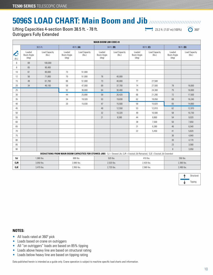
Structural
Tipping
Data published herein is intended as a guide only. Crane operation is subject to machine specific load charts and information.
NOTES:
• All loads rated at 360º pick • Loads based on crane on outriggers • All “on outriggers” loads are based on 85% tipping • Loads above heavy line are based on structural rating • Loads below heavy line are based on tipping rating
Lifting Capacities 4-section Boom 38.5 ft. - 78 ft. Outriggers Fully Extended
5096S LOAD CHART: Main Boom and Jib23.2 ft. (7.07 m) (100%) 360º
/ / / / / / / / / / / / / / / / / / / / / / / / / / / / / / /
MAIN BOOM LMI CODE #3
30.5 ft. 48 ft. (A) 64 ft. (B) 80 ft. (C) 96 ft. (D)
Loaded Boom Angle
(deg)
Load Capacity (lbs.)
Loaded Boom Angle
(deg)
Load Capacity (lbs.)
Loaded Boom Angle
(deg)
Load Capacity (lbs.)
Loaded Boom Angle
(deg)
Load Capacity (lbs.)
Loaded Boom Angle
(deg)
Load Capacity (lbs.)
6 69 100,000
8 65 90,400
10 61 80,000 73 51,000
12 56 71,800 70 51,000 76 40,000
15 49 61,700 66 51,000 73 40,000 77 27,500
20 34 46,100 59 47,000 69 37,700 74 27,500 78 18,000
25 52 36,800 64 30,400 70 24,300 75 18,000
30 44 25,890 59 26,420 66 21,280 72 17,500
35 34 19,320 53 19,830 62 19,050 69 16,240
40 20 15,030 47 15,500 58 15,820 65 14,660
45 40 12,550 53 12,810 62 12,970
50 32 10,320 49 10,580 58 10,730
55 21 8,590 44 8,860 54 9,020
60 38 7,500 50 7,650
65 31 6,380 46 6,540
70 22 5,450 41 5,620
75 36 4,840
80 30 4,170
85 23 3,580
90 8 3,050
DEDUCTIONS FROM MAIN BOOM CAPACITIES FOR STOWED JIBS - SJ = Stowed Jib, EJR = Erected Jib Retracted, EJE = Erected Jib Extended
SJ 1,080 lbs. 690 lbs. 520 lbs. 410 lbs. 350 lbs.
EJR 3,050 lbs. 2,680 lbs. 2,520 lbs. 2,420 lbs. 2,360 lbs.
EJE 3,470 lbs. 2,950 lbs. 2,720 lbs. 2,580 lbs. 2,490 lbs.
(ft.)
11
Data published herein is intended as a guide only. Crane operation is subject to machine specific load charts and information.
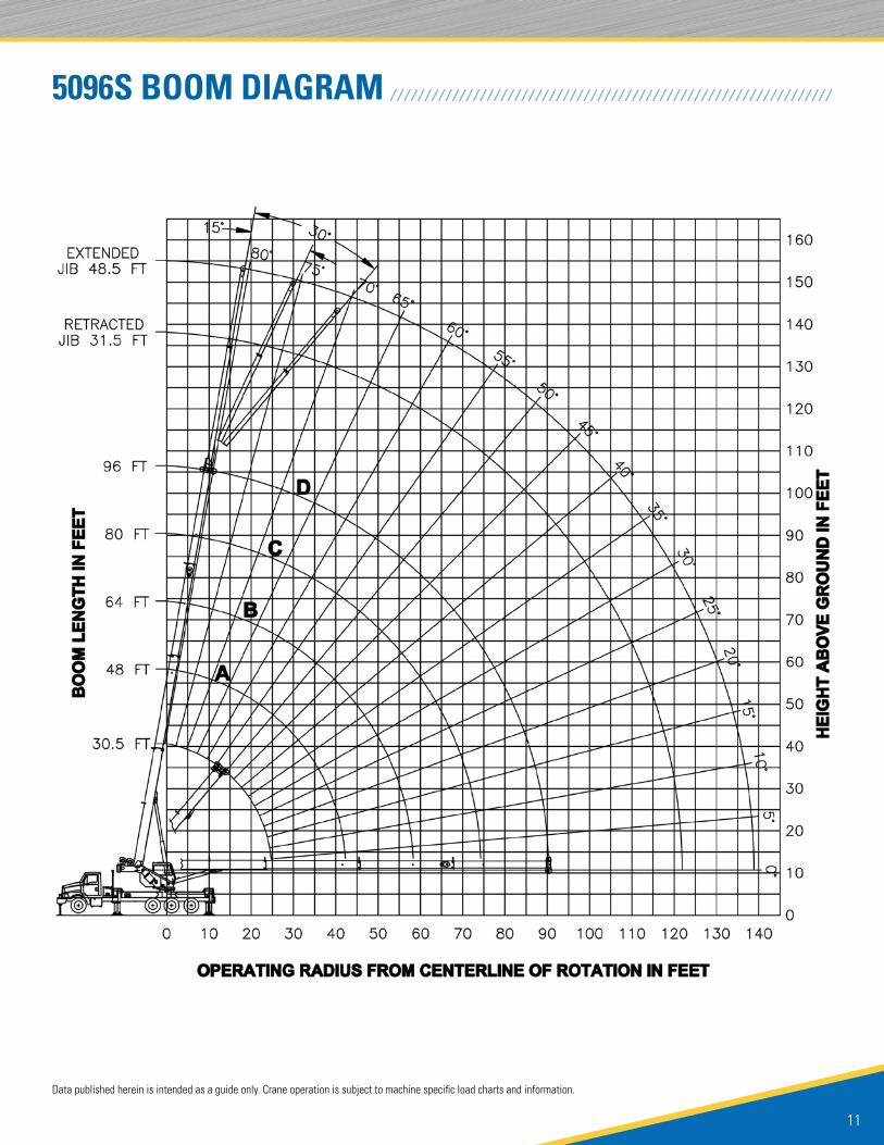
5096S BOOM DIAGRAM / / / / / / / / / / / / / / / / / / / / / / / / / / / / / / / / / / / / / / / / / / / / / / / / / / / / / / / / / / / / / / / /

TC500 SERIES TELESCOPIC CRANE
12
Lifting Capacities 4-section Boom 34 ft. - 110 ft. 1 or 2-section Jib 32 ft. - 49 ft. - Full Outrigger Extension
50110S LOAD CHART: Main Boom and Jib23.2 ft. (7,1 m) (100%) 360º
/ / / / / / / / / / / / / / / / / / / / / / / / / / /
MAIN BOOM LMI CODE #3
34 ft. 50 ft. (A) 65 ft. (B) 80 ft. (C) 95 ft. (D) 110 ft. (E)
Loaded Boom Angle
(deg)
Load Capacity (lbs.)
Loaded Boom Angle
(deg)
Load Capacity (lbs.)
Loaded Boom Angle
(deg)
Load Capacity (lbs.)
Loaded Boom Angle
(deg)
Load Capacity (lbs.)
Loaded Boom Angle
(deg)
Load Capacity (lbs.)
Loaded Boom Angle
(deg)
Load Capacity (lbs.)
6 71 100,000
8 67.5 88,500
10 63.5 78,200 73 51,000
12 60 70,200 70.5 51,000 76 40,000
15 53.5 60,600 67 51,000 73 40,000 77 28,230
20 42 46,100 60.5 46,600 68.5 38,810 73.5 28,230 76.5 20,000
25 26.5 35,800 53.5 36,600 63.5 33,150 69.5 24,350 73.5 20,000 76.5 15,500
30 45.5 25,730 58.5 26,280 65.5 21,280 70.5 18,680 74 15,500
35 36.5 19,090 53 19,610 61.5 19,000 67.5 16,580 71.5 14,660
40 25 14,760 47 15,280 57.5 15,560 64 14,820 69 13,270
45 40.5 12,240 53 12,510 60.5 12,690 66 11,960
50 32.5 9,980 48 10,250 57 10,420 63 10,540
55 22.5 8,230 43 8,510 53 8,680 60 8,800
60 37 7,130 49 7,300 56.5 7,410
65 30 6,000 44.5 6,170 53.5 6,280
70 21 5,050 40 5,240 50 5,350
75 34.5 4,440 46 4,560
80 28 3,770 42 3,880
85 20 3,170 37.5 3,300
90 33 2,790
95 27 2,330
100 19 1,920
DEDUCTIONS FROM MAIN BOOM CAPACITIES FOR STOWED JIBS - SJ = Stowed Jib, EJR = Erected Jib Retracted, EJE = Erected Jib Extended
SJ 1,150 lbs. 780 lbs. 600 lbs. 490 lbs. 420 lbs. 360 lbs.
EJR 2,940 lbs. 2,650 lbs. 2,510 lbs. 2,420 lbs. 2,360 lbs. 2,320 lbs.
EJE 3,320 lbs. 2,910 lbs. 2,710 lbs. 2,580 lbs. 2,500 lbs. 2,430 lbs.
(ft.)
Structural
Tipping
NOTES:
• All loads rated at 360º pick
• Loads based on crane on outriggers
• All “on outriggers” loads are based on 85% tipping
• Loads above heavy line are based on structural rating
• Loads below heavy line are based on tipping rating
JIB LOAD CAPACITIES
0º Offset - Code #8 15º Offset - Code #10 30º Offset - Code #12
Loaded Boom Angle (deg)
Full 360º (lbs.)
Loaded Boom Angle (deg)
Full 360º (lbs.)
Loaded Boom Angle (deg)
Full 360º (lbs.)
35 76.5 7,300
40 74.5 7,300
45 72.5 7,300 76 6,500
50 70.5 7,300 73.5 6,500 76 5,800
55 68.5 6,980 71.5 6,500 74 5,800
60 66.5 6,600 69.5 6,120 72 5,750
65 64 6,230 67 5,780 69.5 5,450
70 62 5,330 65 5,450 67 5,160
75 59.5 4,520 62.5 4,930 64.5 4,900
80 57 3,830 60 4,200 62 4,500
JIB LOAD CAPACITIES
0º Offset - Code #8 15º Offset - Code #10 30º Offset - Code #12
Loaded Boom Angle (deg)
Full 360º (lbs.)
Loaded Boom Angle (deg)
Full 360º (lbs.)
Loaded Boom Angle (deg)
Full 360º (lbs.)
85 54.5 3,240 57.5 3,570 59.5 3,830
90 52 2,720 54.5 3,010 56.5 3,250
95 49 2,260 51.5 2,530 53.5 2,730
100 46 1,860 48.5 2,090 50.5 2,260
105 43 1,490 45.5 1,700 47 1,840
110 39.5 1,170 42 1,350 43.5 1,460
115 35.5 870 38 1,020 39 1,110
120 34.5 790
125
130
(ft.) (ft.)
Data published herein is intended as a guide only. Crane operation is subject to machine specific load charts and information.
13
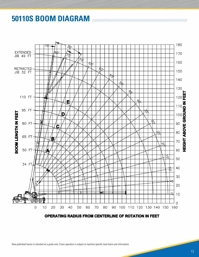
50110S BOOM DIAGRAM / / / / / / / / / / / / / / / / / / / / / / / / / / / / / / / / / / / / / / / / / / / / / / / / / / / / / / / / / / / / /
Data published herein is intended as a guide only. Crane operation is subject to machine specific load charts and information.

TC500 SERIES TELESCOPIC CRANE
14
Lifting Capacities 4-section Boom 34 ft. - 110 ft. 1 or 2-section Jib 32 ft. - 49 ft. - Full Outrigger Extension
50110SHL LOAD CHART: Main Boom and Jib23.2 ft. (7,1 m) (100%) 360º
/ / / / / / / / / / / / / / / / / / / / / / /
MAIN BOOM LMI CODE #3
34 ft. 50 ft. (A) 65 ft. (B) 80 ft. (C) 95 ft. (D) 110 ft. (E)
Loaded Boom Angle
(deg)
Load Capacity (lbs.)
Loaded Boom Angle
(deg)
Load Capacity (lbs.)
Loaded Boom Angle
(deg)
Load Capacity (lbs.)
Loaded Boom Angle
(deg)
Load Capacity (lbs.)
Loaded Boom Angle
(deg)
Load Capacity (lbs.)
Loaded Boom Angle
(deg)
Load Capacity (lbs.)
6 71 100,000
8 67.5 88,500
10 63.5 78,200 73 51,000
12 60 70,200 70.5 51,000 76 40,000
15 53.5 60,600 67 51,000 73 40,000 77 28,230
20 42 48,400 60.5 46,600 68.5 38,810 73.5 28,230 76.5 20,000
25 26.5 37,400 53.5 38,300 63.5 33,150 69.5 24,350 73.5 20,000 76.5 15,500
30 45.5 30,700 58.5 29,000 65.5 21,280 70.5 18,680 74 15,500
35 36.5 24,440 53 24,960 61.5 19,000 67.5 16,580 71.5 14,660
40 25 19,170 47 19,680 57.5 16,870 64 14,820 69 13,270
45 40.5 15,980 53 15,120 60.5 13,330 66 11,960
50 32.5 13,240 48 13,510 57 12,050 63 10,850
55 22.5 11,110 43 11,400 53 10,920 60 9,950
60 37 9,720 49 9,880 56.5 9,210
65 30 8,340 44.5 8,520 53.5 8,410
70 21 7,200 40 7,380 50 7,490
75 34.5 6,420 46 6,530
80 28 5,590 42 5,710
85 20 4,880 37.5 5,000
90 33 4,380
95 27 3,830
100 19 3,340
DEDUCTIONS FROM MAIN BOOM CAPACITIES FOR STOWED JIBS - SJ = Stowed Jib, EJR = Erected Jib Retracted, EJE = Erected Jib Extended
SJ 1,150 lbs. 780 lbs. 600 lbs. 490 lbs. 420 lbs. 360 lbs.
EJR 2,940 lbs. 2,650 lbs. 2,510 lbs. 2,420 lbs. 2,360 lbs. 2,320 lbs.
EJE 3,320 lbs. 2,910 lbs. 2,710 lbs. 2,580 lbs. 2,500 lbs. 2,430 lbs.
(ft.)
Structural
Tipping
NOTES:
• All loads rated at 360º pick
• Loads based on crane on outriggers
• All “on outriggers” loads are based on 85% tipping
• Loads above heavy line are based on structural rating
• Loads below heavy line are based on tipping rating
32 ft. RETRACTED JIB LOAD CAPACITIES
0º Offset - Code #8 15º Offset - Code #10 30º Offset - Code #12
Loaded Boom Angle (deg)
Full 360º (lbs.)
Loaded Boom Angle (deg)
Full 360º (lbs.)
Loaded Boom Angle (deg)
Full 360º (lbs.)
35 76.5 7,300
40 74.5 7,300
45 72.5 7,300 76 6,500
50 70.5 7,300 73.5 6,500 76 5,800
55 68.5 6,980 71.5 6,500 74 5,800
60 66.5 6,660 69.5 6,120 72 5,750
65 64 6,230 67 5,780 69.5 5,450
70 62 5,870 65 5,450 67 5,160
75 59.5 5,530 62.5 5,160 64.5 4,900
80 57 5,110 60 4,880 62 4,670
85 54.5 4,690 57.5 4,630 59.5 4,450
32 ft. RETRACTED JIB LOAD CAPACITIES
0º Offset - Code #8 15º Offset - Code #10 30º Offset - Code #12
Loaded Boom Angle (deg)
Full 360º (lbs.)
Loaded Boom Angle (deg)
Full 360º (lbs.)
Loaded Boom Angle (deg)
Full 360º (lbs.)
90 52 4,280 54.5 4,400 56.5 4,250
95 49 3,760 51.5 4,030 53.5 4,070
100 46 3,270 48.5 3,510 50.5 3,680
105 43 2,830 45.5 3,040 47 3,180
110 39.5 2,440 42 2,620 43.5 2,730
115 35.5 2,080 38 2,230 39 2,320
120 31.5 1,760 34 1,880 34.5 1,940
125 26.5 1,460 29 1,560 29 1,580
130 20.5 1,190 22 1,250 20 1,230
135 10 930
(ft.) (ft.)
Data published herein is intended as a guide only. Crane operation is subject to machine specific load charts and information.
15
Data published herein is intended as a guide only. Crane operation is subject to machine specific load charts and information.
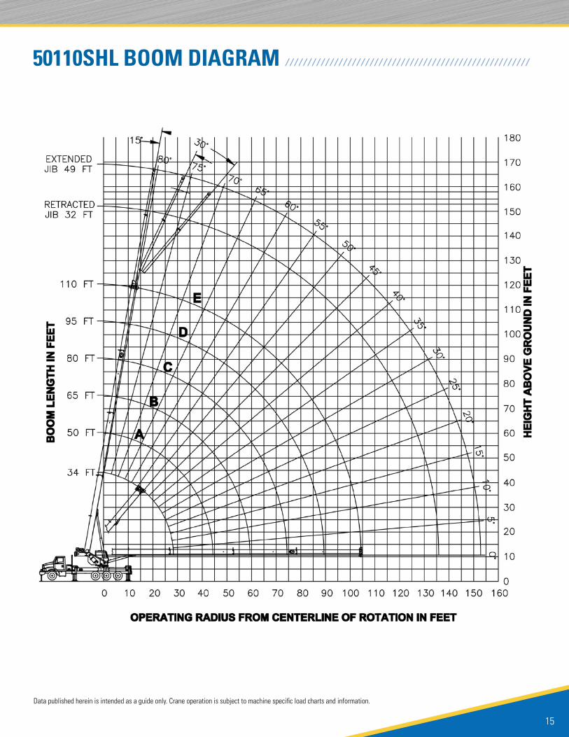
50110SHL BOOM DIAGRAM / / / / / / / / / / / / / / / / / / / / / / / / / / / / / / / / / / / / / / / / / / / / / / / / / / / / / / /

TC500 SERIES TELESCOPIC CRANE
16
Lifting Capacities 4-section Boom 38.5 ft. - 128 ft. 1 or 2-section Jib 32 ft. - 49 ft. - Full Outrigger Extension
50128S LOAD CHART: Main Boom and Jib23.2 ft. (7.07 m) (100%) 360º
/ / / / / / / / / / / / / / / / / / / / / / / / / / / / /
Structural
Tipping
NOTES:
• All loads rated at 360º pick
• Loads based on crane on outriggers
• All “on outriggers” loads are based on 85% tipping
• Loads above heavy line are based on structural rating
• Loads below heavy line are based on tipping rating
MAIN BOOM LMI CODE #3
38.5 ft. 53 ft. (A) 66 ft. (B) 78 ft. (C) 91 ft. (D) 103 ft. (E) 116 ft. (F) 128 ft. (G)
Loaded Boom Angle (deg)
Full 360º (lbs.)
Loaded Boom Angle (deg)
Full 360º (lbs.)
Loaded Boom Angle (deg)
Full 360º (lbs.)
Loaded Boom Angle (deg)
Full 360º (lbs.)
Loaded Boom Angle (deg)
Full 360º (lbs.)
Loaded Boom Angle (deg)
Full 360º (lbs.)
Loaded Boom Angle (deg)
Full 360º (lbs.)
Loaded Boom Angle (deg)
Full 360º (lbs.)
6 73.5 100,000
8 70.5 86,600
10 67 76,400 74.5 51,000 78 51,000
12 64 68,400 72.5 51,000 76.5 51,000 79 41,710
15 59 59,000 68.5 51,000 73.5 46,650 77 37,880 79 30,000
20 49.5 47,670 62.5 45,700 69 39,300 73 32,140 76 26,010 78.5 22,790
25 38.5 36,900 56 37,680 64 33,450 69 27,890 72.5 22,620 75.5 20,160 78 17,660
30 23.5 27,090 49.5 28,290 59 28,850 65 24,230 69.5 20,000 72.5 18,080 75.5 16,060 77.5 13,000
35 41.5 20,960 54 21,480 61 21,310 66 17,710 70.5 16,070 73 14,480 75.5 12,760
40 32 16,200 48 16,700 56.5 16,990 62.5 15,740 67.5 14,360 70.5 13,050 73 11,760
45 18.5 12,830 42 13,350 52 13,630 59 13,840 64 12,900 68 11,780 71 10,800
50 34.5 10,860 46.5 11,140 55 11,340 60.5 11,480 65 10,640 68.5 10,000
55 25 8,930 41 9,220 50.5 9,420 57 9,550 62 9,660 66 9,130
60 7 7,350 35 7,690 46.5 7,890 53.5 8,020 59 8,130 63.5 8,200
65 27 6,440 41.5 6,650 50 6,780 56 6,880 60.5 6,950
70 16 5,390 36.5 5,610 46 5,740 53 5,850 58 5,920
75 30 4,740 41.5 4,870 49.5 4,970 55 5,050
80 22 3,980 37 4,120 46 4,230 52 4,300
85 7 3,330 31.5 3,480 42.5 3,580 49 3,650
90 25 2,910 38 3,020 46 3,090
95 15.5 2,390 33.5 2,520 42 2,590
100 28.5 2,070 38.5 2,150
105 21.5 1,670 34 1,760
110 7.5 1,290 29.5 1,400
115 23.5 1,070
120 15 770
DEDUCTIONS FROM MAIN BOOM CAPACITIES FOR STOWED JIBS - SJ = Stowed Jib, EJR = Erected Jib Retracted, EJE = Erected Jib Extended
SJ 1,230 lbs. 890 lbs. 720 lbs. 610 lbs. 520 lbs. 460 lbs. 410 lbs. 370 lbs.
EJR 2,840 lbs. 2,620 lbs. 2,500 lbs. 2,430 lbs. 2,370 lbs. 2,330 lbs. 2,300 lbs. 2,280 lbs.
EJE 3,170 lbs. 2,860 lbs. 2,700 lbs. 2,600 lbs. 2,520 lbs. 2,460 lbs. 2,410 lbs. 2,380 lbs.
(ft.)
JIB LOAD CAPACITIES
0º Offset - Code #8 15º Offset - Code #10 30º Offset - Code #12
Loaded Boom Angle (deg)
Full 360º (lbs.)
Loaded Boom Angle (deg)
Full 360º (lbs.)
Loaded Boom Angle (deg)
Full 360º (lbs.)
35 78 5,400
40 76.5 5,400 79.5 5,400
45 75 5,400 78 5,400
50 73.5 5,400 76.5 5,400 79 5,400
55 72 5,400 74.5 5,400 77 5,400
60 70 5,400 73 5,400 75 5,400
65 68.5 5,400 71 5,400 73 5,240
70 66.5 5,210 69 5,230 71.5 4,990
75 64.5 4,740 67 4,970 69.5 4,750
JIB LOAD CAPACITIES
0º Offset - Code #8 15º Offset - Code #10 30º Offset - Code #12
Loaded Boom Angle (deg)
Full 360º (lbs.)
Loaded Boom Angle (deg)
Full 360º (lbs.)
Loaded Boom Angle (deg)
Full 360º (lbs.)
80 62.5 4,140 65 4,570 67.5 4,520
85 60.5 3,490 63 3,890 65 4,220
90 58 2,920 61 3,280 63 3,580
95 55.5 2,410 58.5 2,740 60.5 3,010
100 53 1,970 56 2,270 58 2,500
105 50.5 1,570 53.5 1,840 55.5 2,040
110 48 1,210 50.5 1,450 52.5 1,630
115 45.5 880 48 1,100 49.5 1,260
120 46.5 910
(ft.) (ft.)
Data published herein is intended as a guide only. Crane operation is subject to machine specificload charts and information.

17
Data published herein is intended as a guide only. Crane operation is subject to machine specific load charts and information.
50128S BOOM DIAGRAM / / / / / / / / / / / / / / / / / / / / / / / / / / / / / / / / / / / / / / / / / / / / / / / / / / / / / / / / / / / / / /

TC500 SERIES TELESCOPIC CRANE
18
Lifting Capacities 4-section Boom 38.5 ft. - 128 ft. 1 or 2-section Jib 31 ft. - 55 ft. - Full Outrigger Extension
50128SHL LOAD CHART: Main Boom and Jib23.2 ft. (7.07 m) (100%) 360º
/ / / / / / / / / / / / / / / / / / / / / /
Structural
Tipping
NOTES:
• All loads rated at 360º pick
• Loads based on crane on outriggers
• All “on outriggers” loads are based on 85% tipping
• Loads above heavy line are based on structural rating
• Loads below heavy line are based on tipping rating
MAIN BOOM LMI CODE #3
38.5 ft. 53 ft. (A) 66 ft. (B) 78 ft. (C) 91 ft. (D) 103 ft. (E) 116 ft. (F) 128 ft. (G)
Loaded Boom Angle (deg)
Full 360º (lbs.)
Loaded Boom Angle (deg)
Full 360º (lbs.)
Loaded Boom Angle (deg)
Full 360º (lbs.)
Loaded Boom Angle (deg)
Full 360º (lbs.)
Loaded Boom Angle (deg)
Full 360º (lbs.)
Loaded Boom Angle (deg)
Full 360º (lbs.)
Loaded Boom Angle (deg)
Full 360º (lbs.)
Loaded Boom Angle (deg)
Full 360º (lbs.)
6 73.5 100,000
8 70.5 86,600
10 67 76,400 74.5 51,000 78 51,000
12 64 68,400 72.5 51,000 76.5 51,000 79 41,710
15 59 59,000 68.5 51,000 73.5 46,650 77 37,880 79 30,000
20 49.5 47,700 62.5 45,700 69 39,300 73 32,140 76 26,010 78.5 22,790
25 38.5 38,300 56 38,400 64 33,450 69 27,890 72.5 22,620 75.5 20,160 78 17,660
30 23.5 30,200 49.5 31,590 59 29,140 65 24,230 69.5 20,000 72.5 18,080 75.5 16,060 77.5 13,000
35 41.5 23,590 54 24,100 61 21,310 66 17,710 70.5 16,070 73 14,480 75.5 12,760
40 32 18,360 48 18,860 56.5 19,150 62.5 15,740 67.5 14,360 70.5 13,050 73 11,760
45 18.5 14,670 42 15,190 52 15,470 59 14,050 64 12,900 68 11,780 71 10,800
50 34.5 12,460 46.5 12,740 55 12,620 60.5 11,610 65 10,640 68.5 10,000
55 25 10,350 41 10,630 50.5 10,830 57 10,500 62 9,890 66 9,130
60 7 8,620 35 8,960 46.5 9,160 53.5 9,290 59 8,970 63.5 8,320
65 27 7,590 41.5 7,800 50 7,930 56 8,030 60.5 7,570
70 16 6,440 36.5 6,660 46 6,790 53 6,900 58 6,910
75 30 5,700 41.5 5,840 49.5 5,940 55 6,010
80 22 4,880 37 5,020 46 5,130 52 5,200
85 7 4,140 31.5 4,310 42.5 4,420 49 4,490
90 25 3,690 38 3,800 46 3,870
95 15.5 3,130 33.5 3,260 42 3,330
100 28.5 2,770 38.5 2,850
105 21.5 2,330 34 2,410
110 7.5 1,920 29.5 2,020
115 23.5 1,660
120 15 1,330
DEDUCTIONS FROM MAIN BOOM CAPACITIES FOR STOWED JIBS - SJ = Stowed Jib, EJR = Erected Jib Retracted, EJE = Erected Jib Extended
SJ 1,230 lbs. 890 lbs. 720 lbs. 610 lbs. 520 lbs. 460 lbs. 410 lbs. 370 lbs.
EJR 2,840 lbs. 2,620 lbs. 2,500 lbs. 2,430 lbs. 2,370 lbs. 2,330 lbs. 2,300 lbs. 2,280 lbs.
EJE 3,170 lbs. 2,860 lbs. 2,700 lbs. 2,600 lbs. 2,520 lbs. 2,460 lbs. 2,410 lbs. 2,380 lbs.
(ft.)
JIB LOAD CAPACITIES
0º Offset - Code #8 15º Offset - Code #10 30º Offset - Code #12
Loaded Boom Angle (deg)
Full 360º (lbs.)
Loaded Boom Angle (deg)
Full 360º (lbs.)
Loaded Boom Angle (deg)
Full 360º (lbs.)
35 78 5,400
40 76.5 5,400 79.5 5,400
45 75 5,400 78 5,400
50 73.5 5,400 76.5 5,400 79 5,400
55 72 5,400 74.5 5,400 77 5,400
60 70 5,400 73 5,400 75 5,400
65 68.5 5,400 71 5,400 73 5,240
70 66.5 5,210 69 5,230 71.5 4,990
75 64.5 4,740 67 4,970 69.5 4,750
JIB LOAD CAPACITIES
0º Offset - Code #8 15º Offset - Code #10 30º Offset - Code #12
Loaded Boom Angle (deg)
Full 360º (lbs.)
Loaded Boom Angle (deg)
Full 360º (lbs.)
Loaded Boom Angle (deg)
Full 360º (lbs.)
80 62.5 4,300 65 4,570 67.5 4,520
85 60.5 3,890 63 4,140 65 4,310
90 58 3,510 61 3,740 63 3,930
95 55.5 3,150 58.5 3,360 60.5 3,540
100 53 2,660 56 2,960 58 3,170
105 50.5 2,220 53.5 2,490 55.5 2,700
110 48 1,830 50.5 2,080 52.5 2,250
115 45.5 1,480 48 1,700 49.5 1,850
120 42.5 1,160 45 1,350 46.5 1,480
125 39.5 860 42 1,030 43 1,130
(ft.) (ft.)
Data published herein is intended as a guide only. Crane operation is subject to machine specific load charts and information.

19
50128SHL BOOM DIAGRAM / / / / / / / / / / / / / / / / / / / / / / / / / / / / / / / / / / / / / / / / / / / / / / / / / / / / / / / /
Data published herein is intended as a guide only. Crane operation is subject to machine specific load charts and information.

TC500 SERIES TELESCOPIC CRANE
20
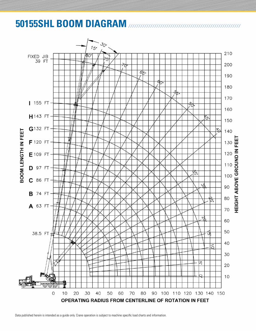
360ºLifting Capacities 5-section Boom 38.5 ft. - 155 ft. 39 ft. Fixed Jib - Full Outrigger Extension
50155S LOAD CHART: Main Boom and Jib23.2 ft. (7,1 m) (100%)
/ / / / / / / / / / / / / / / / / / / / / / / / / / / / /
Data published herein is intended as a guide only. Crane operation is subject to machine specific load charts and information.
MAIN BOOM LMI CODE #3
38.5 ft. 63 ft. (A) 74 ft. (B) 86 ft. (C) 97 ft. (D) 109 ft. (E) 120 ft. (F) 132 ft. (G) 143 ft. (H) 155 ft. (I)
Loaded Boom Angle (deg)
Full 360º (lbs.)
Loaded Boom Angle (deg)
Full 360º (lbs.)
Loaded Boom Angle (deg)
Full 360º (lbs.)
Loaded Boom Angle (deg)
Full 360º (lbs.)
Loaded Boom Angle (deg)
Full 360º (lbs.)
Loaded Boom Angle (deg)
Full 360º (lbs.)
Loaded Boom Angle (deg)
Full 360º (lbs.)
Loaded Boom Angle (deg)
Full 360º (lbs.)
Loaded Boom Angle (deg)
Full 360º (lbs.)
Loaded Boom Angle (deg)
Full 360º (lbs.)
6 73.5 100,000
8 70.5 85,400
10 67 75,100 77 40,000
12 64 67,100 75 40,000 78 37,700
15 58.8 57,700 72.5 40,000 75.5 36,340 78.5 31,000
20 49 46,070 67.5 38,250 72 33,380 75 28,200 77.5 24,120
25 38 35,280 62.5 35,040 67.5 30,620 71.5 25,970 74.5 22,200 77 18,000 79 16,260
30 22.5 27,920 57 29,140 63 28,020 68 23,950 71 20,480 74 17,000 76.5 15,280 78 13,500 79.5 11,500
35 51.5 21,500 58.5 21,830 64 22,080 68 18,670 71.5 15,920 74 14,270 76 12,900 77.5 11,300 79 9,000
40 45 16,460 54 16,770 60.5 17,010 65 17,170 68.5 14,700 71.5 13,310 74 12,000 75.5 11,000 77 9,000
45 38 12,910 48.5 13,220 56.5 13,220 61.5 13,610 65.5 13,570 69 12,410 71.5 11,300 73.5 10,460 75.5 9,000
50 29.5 10,280 43 10,590 52 10,820 58 10,970 62.5 11,100 66 11,180 69 10,550 71.5 9,460 73.5 8,800
55 17 8,210 37 8,560 47.5 8,790 54 8,940 59.5 9,060 63.5 9,150 67 9,220 69.5 8,880 71.5 8,320
60 29 6,940 42.5 7,180 50 7,320 56 7,440 60.5 7,530 64.5 7,600 67.5 7,650 69.5 7,700
65 19 5,600 37 5,860 46 6,010 53 6,130 57.5 6,210 62 6,280 65 6,330 67.5 6,380
70 30.5 4,760 41.5 4,920 49 5,040 54.5 5,120 59 5,190 62.5 5,240 65.5 5,290
75 22.5 3,830 36.5 3,990 45.5 4,120 51.5 4,200 56.5 4,270 60.5 4,320 63.5 4,360
80 7.5 2,990 30.5 3,200 41.5 3,330 48 3,410 53.5 3,480 58 3,530 61.5 3,570
85 23.5 2,510 37 2,640 44.5 2,730 50.5 2,800 55.5 2,850 59 2,890
90 12 1,880 32 2,040 41 2,130 47.5 2,200 52.5 2,250 57 2,300
95 25.5 1,510 36.5 1,610 44.5 1,680 50 1,730 54.5 1,770
100 17 1,030 32 1,140 41 1,210 47 1,260 52 1,310
105 44 850 49.5 890
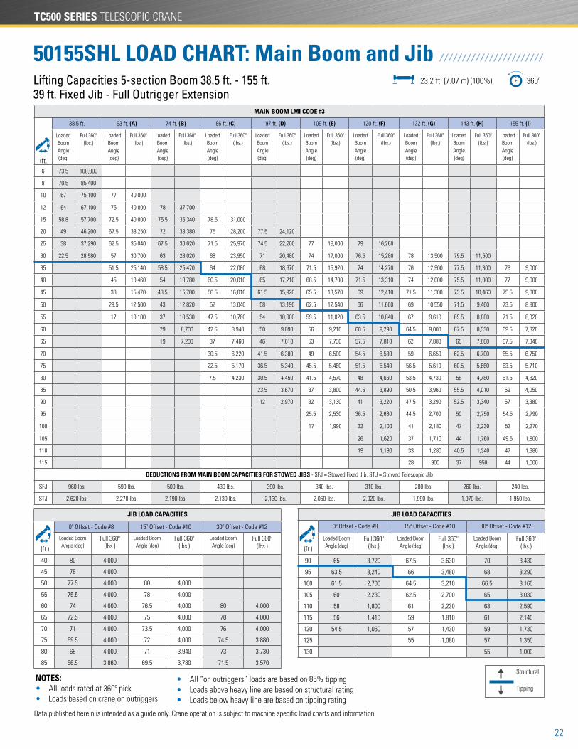
DEDUCTIONS FROM MAIN BOOM CAPACITIES FOR STOWED JIBS - SFJ = Stowed Fixed Jib, STJ = Stowed Telescopic Jib
SFJ 960 lbs. 590 lbs. 500 lbs. 430 lbs. 390 lbs. 340 lbs. 310 lbs. 280 lbs. 260 lbs. 240 lbs.
STJ 2,620 lbs. 2,270 lbs. 2,190 lbs. 2,130 lbs. 2,130 lbs. 2,050 lbs. 2,020 lbs. 1,990 lbs. 1,970 lbs. 1,950 lbs.
(ft.)
JIB LOAD CAPACITIES
0º Offset Code - #8 15º Offset - Code #10 30º Offset - Code #12
Loaded Boom Angle (deg)
Full 360º (lbs.)
Loaded Boom Angle (deg)
Full 360º (lbs.)
Loaded Boom Angle (deg)
Full 360º (lbs.)
40 80 4,000
45 78 4,000
50 77.5 4,000 80 4,000
55 75.5 4,000 78 4,000
60 74 4,000 76.5 4,000 80 4,000
65 72.5 4,000 75 4,000 78 4,000
70 71 4,000 73.5 4,000 76 4,000
75 69.5 4,000 72 4,000 74.5 3,880
80 68 4,000 71 3,940 73 3,730
JIB LOAD CAPACITIES
0º Offset 15º Offset - Code #10 30º Offset - Code #12
Loaded Boom Angle (deg)
Full 360º (lbs.)
Loaded Boom Angle (deg)
Full 360º (lbs.)
Loaded Boom Angle (deg)
Full 360º (lbs.)
85 66.5 3,360 69.5 3,780 71.5 3,570
90 65 2,750 67.5 3,350 70 3,430
95 63.5 2,210 66 2,760 68 3,230
100 61.5 1,740 64.5 2,250 66.5 2,670
105 60 1,310 62.5 1,780 65 2,170
110 58 930 61 1,370 63 1,720
115 59 990 61 1,310
120 59 940
125
(ft.) (ft.)
Structural
Tipping
NOTES: • All loads rated at 360º pick • Loads based on crane on outriggers
• All “on outriggers” loads are based on 85% tipping • Loads above heavy line are based on structural rating • Loads below heavy line are based on tipping rating

21
Data published herein is intended as a guide only. Crane operation is subject to machine specific load charts and information.
50155S BOOM DIAGRAM / / / / / / / / / / / / / / / / / / / / / / / / / / / / / / / / / / / / / / / / / / / / / / / / / / / / / / / / / / / / /
TC500 SERIES TELESCOPIC CRANE
22
Lifting Capacities 5-section Boom 38.5 ft. - 155 ft. 39 ft. Fixed Jib - Full Outrigger Extension
50155SHL LOAD CHART: Main Boom and Jib23.2 ft. (7.07 m) (100%) 360º
/ / / / / / / / / / / / / / / / / / / / / / /
Data published herein is intended as a guide only. Crane operation is subject to machine specific load charts and information.
MAIN BOOM LMI CODE #3
38.5 ft. 63 ft. (A) 74 ft. (B) 86 ft. (C) 97 ft. (D) 109 ft. (E) 120 ft. (F) 132 ft. (G) 143 ft. (H) 155 ft. (I)
Loaded Boom Angle (deg)
Full 360º (lbs.)
Loaded Boom Angle (deg)
Full 360º (lbs.)
Loaded Boom Angle (deg)
Full 360º (lbs.)
Loaded Boom Angle (deg)
Full 360º (lbs.)
Loaded Boom Angle (deg)
Full 360º (lbs.)
Loaded Boom Angle (deg)
Full 360º (lbs.)
Loaded Boom Angle (deg)
Full 360º (lbs.)
Loaded Boom Angle (deg)
Full 360º (lbs.)
Loaded Boom Angle (deg)
Full 360º (lbs.)
Loaded Boom Angle (deg)
Full 360º (lbs.)
6 73.5 100,000
8 70.5 85,400
10 67 75,100 77 40,000
12 64 67,100 75 40,000 78 37,700
15 58.8 57,700 72.5 40,000 75.5 36,340 78.5 31,000
20 49 46,200 67.5 38,250 72 33,380 75 28,200 77.5 24,120
25 38 37,290 62.5 35,040 67.5 30,620 71.5 25,970 74.5 22,200 77 18,000 79 16,260
30 22.5 28,580 57 30,700 63 28,020 68 23,950 71 20,480 74 17,000 76.5 15,280 78 13,500 79.5 11,500
35 51.5 25,140 58.5 25,470 64 22,080 68 18,670 71.5 15,920 74 14,270 76 12,900 77.5 11,300 79 9,000
40 45 19,460 54 19,780 60.5 20,010 65 17,210 68.5 14,700 71.5 13,310 74 12,000 75.5 11,000 77 9,000
45 38 15,470 48.5 15,780 56.5 16,010 61.5 15,920 65.5 13,570 69 12,410 71.5 11,300 73.5 10,460 75.5 9,000
50 29.5 12,500 43 12,820 52 13,040 58 13,190 62.5 12,540 66 11,600 69 10,550 71.5 9,460 73.5 8,800
55 17 10,180 37 10,530 47.5 10,760 54 10,900 59.5 11,020 63.5 10,840 67 9,610 69.5 8,880 71.5 8,320
60 29 8,700 42.5 8,940 50 9,090 56 9,210 60.5 9,290 64.5 9,000 67.5 8,330 69.5 7,820
65 19 7,200 37 7,460 46 7,610 53 7,730 57.5 7,810 62 7,880 65 7,800 67.5 7,340
70 30.5 6,220 41.5 6,380 49 6,500 54.5 6,580 59 6,650 62.5 6,700 65.5 6,750
75 22.5 5,170 36.5 5,340 45.5 5,460 51.5 5,540 56.5 5,610 60.5 5,660 63.5 5,710
80 7.5 4,230 30.5 4,450 41.5 4,570 48 4,660 53.5 4,730 58 4,780 61.5 4,820
85 23.5 3,670 37 3,800 44.5 3,890 50.5 3,960 55.5 4,010 59 4,050
90 12 2,970 32 3,130 41 3,220 47.5 3,290 52.5 3,340 57 3,380
95 25.5 2,530 36.5 2,630 44.5 2,700 50 2,750 54.5 2,790
100 17 1,990 32 2,100 41 2,180 47 2,230 52 2,270
105 26 1,620 37 1,710 44 1,760 49.5 1,800
110 19 1,190 33 1,280 40.5 1,340 47 1,380
115 28 900 37 950 44 1,000
DEDUCTIONS FROM MAIN BOOM CAPACITIES FOR STOWED JIBS - SFJ = Stowed Fixed Jib, STJ = Stowed Telescopic Jib
SFJ 960 lbs. 590 lbs. 500 lbs. 430 lbs. 390 lbs. 340 lbs. 310 lbs. 280 lbs. 260 lbs. 240 lbs.
STJ 2,620 lbs. 2,270 lbs. 2,190 lbs. 2,130 lbs. 2,130 lbs. 2,050 lbs. 2,020 lbs. 1,990 lbs. 1,970 lbs. 1,950 lbs.
(ft.)
JIB LOAD CAPACITIES
0º Offset - Code #8 15º Offset - Code #10 30º Offset - Code #12
Loaded Boom Angle (deg)
Full 360º (lbs.)
Loaded Boom Angle (deg)
Full 360º (lbs.)
Loaded Boom Angle (deg)
Full 360º (lbs.)
40 80 4,000
45 78 4,000
50 77.5 4,000 80 4,000
55 75.5 4,000 78 4,000
60 74 4,000 76.5 4,000 80 4,000
65 72.5 4,000 75 4,000 78 4,000
70 71 4,000 73.5 4,000 76 4,000
75 69.5 4,000 72 4,000 74.5 3,880
80 68 4,000 71 3,940 73 3,730
85 66.5 3,860 69.5 3,780 71.5 3,570
JIB LOAD CAPACITIES
0º Offset - Code #8 15º Offset - Code #10 30º Offset - Code #12
Loaded Boom Angle (deg)
Full 360º (lbs.)
Loaded Boom Angle (deg)
Full 360º (lbs.)
Loaded Boom Angle (deg)
Full 360º (lbs.)
90 65 3,720 67.5 3,630 70 3,430
95 63.5 3,240 66 3,480 68 3,290
100 61.5 2,700 64.5 3,210 66.5 3,160
105 60 2,230 62.5 2,700 65 3,030
110 58 1,800 61 2,230 63 2,590
115 56 1,410 59 1,810 61 2,140
120 54.5 1,060 57 1,430 59 1,730
125 55 1,080 57 1,350
130 55 1,000
(ft.) (ft.)
NOTES: • All loads rated at 360º pick • Loads based on crane on outriggers
• All “on outriggers” loads are based on 85% tipping • Loads above heavy line are based on structural rating • Loads below heavy line are based on tipping rating
Structural
Tipping
23
50155SHL BOOM DIAGRAM / / / / / / / / / / / / / / / / / / / / / / / / / / / / / / / / / / / / / / / / / / / / / / / / / / / / / / / /
Data published herein is intended as a guide only. Crane operation is subject to machine specific load charts and information.
TC500 SERIES TELESCOPIC CRANE
24
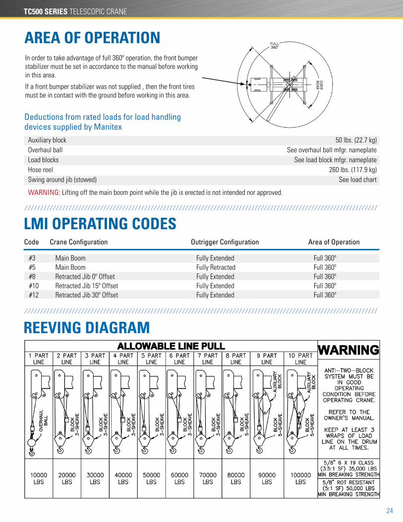
REEVING DIAGRAM
AREA OF OPERATIONIn order to take advantage of full 360º operation, the front bumper stabilizer must be set in accordance to the manual before working in this area.
If a front bumper stabilizer was not supplied , then the front tires must be in contact with the ground before working in this area.
/ / / / / / / / / / / / / / / / / / / / / / / / / / / / / / / / / / / / / / / / / / / / / / / / / / / / / / / / / / / / / / / / / / / / / / / / / / / / / / / / / / / / / / / / / / / / / / / / / / / / / / / / / / / / / / / /
Deductions from rated loads for load handling devices supplied by Manitex
Auxiliary block 50 lbs. (22.7 kg) Overhaul ball See overhaul ball mfgr. nameplate Load blocks See load block mfgr. nameplate Hose reel 260 lbs. (117.9 kg) Swing around jib (stowed) See load chart
WARNING: Lifting off the main boom point while the jib is erected is not intended nor approved.
LMI OPERATING CODESCode Crane Configuration Outrigger Configuration Area of Operation
#3 Main Boom Fully Extended Full 360º #5 Main Boom Fully Retracted Full 360º #8 Retracted Jib 0º Offset Fully Extended Full 360º #10 Retracted Jib 15º Offset Fully Extended Full 360º #12 Retracted Jib 30º Offset Fully Extended Full 360º
/ / / / / / / / / / / / / / / / / / / / / / / / / / / / / / / / / / / / / / / / / / / / / / / / / / / / / / / / / / / / / / / / / / / / / / / / / / / / / / / / / / / / / / / / / / / / / / / / / / / / / / / / / / / / / / / /

25
TECHNICAL DESCRIPTIONS / / / / / / / / / / / / / / / / / / / / / / / / / / / / / / / / / / / / / / / / / / / / / / / / / / / / / / /
vtBoom
Rotation
Outriggers
Hoist, Rope and Hook
Hydraulics
Tiltable Cab/Cab Controls
Operator aids
Boom lengths: Proportional boom • 4-section 96 ft. (29 m) • 4-section 110 ft. (33,5 m) • 4-section 128 ft. (39 m) • 5-section 155 ft. (47 m)5-sheave quick reeve boom pointSelf lubricating slider pads
Boom max. tip height 5096: 153.3 ft. (50,9 m)
Boom max. tip height 50110: 167.1 ft. (51,2 m)
Boom max. tip height 50128: 184.8 ft. (56,3 m)
Boom max. tip height 50155: 202.4 ft. (61,7 m)
Boom angle (min/max): -6º / 80º
Maximum theoretical line speed: 453 fpm (138 mpm)
Maximum theoretical bottom-layer line pull: 13,050 lbs. (5,919 kg)
Main winch cable diameter: 5/8 in. (15,9 mm) rotation resistant
Line length: 5096S & 50110S - 400 ft. (122 m)Line length: 50128 & 50155 - 500 ft. (152 m)
Main winch: Bent axis 2-speed hydraulic motor (activated electrically)
Load block: 5T (4.5 mt) capacity hook with heavy-duty swivel and weight is provided for single line operation.
Outriggers: Out-and-down styleOutrigger monitoring system (for verification only) Outrigger motion alarmFull extension • Front and rear: 23.3 ft. (7,1 m) Middle extension • Front and rear: 15.4 ft. (4,7 m) Full retraction • Front and rear: 7.3 ft. (2,2 m)
ROC Solid - Radio operated handheld controller for outrigger and FBS setup
Slewing brake: Spring-applied pressure released automatic brake
Slewing speed: 1.5 - 2 rpm. (nominal)Boom rotation: 360º continuous
Ball-bearing swing circle with external gearDouble-reduction planetary gearbox driven by hydraulic motor
8-bolt direct mounted PTO and SAE C output (factory mounted units only)3-section vane pump, SAE C inputHydraulic reservoir capacity: 115 gal. (435 L)Pump sections @ 2000 rpm with 100 psi • Shaft end pump: 41.67 gpm (158 lpm) • Center pump: 28.3 gpm (107 lpm) • Cover end pump: 11.7 gpm (44 lpm)
Wired LMI with crane function cut-offs for overload protection, wired anti-two block system, graphical display, event recorder, WADS - Work Area Definition System
1
Controls:
PLC crane controller, CANBUS communication, J1939 truck engine communication capability, elec-tronic hand and foot throttle, Hirschmann/PAT iScout D3 LMI system
Standard features:
Curved glass, 0º to 20º cab tilt, Automotive door, heated cloth seat, 8 seat adjustments, lumbar support and adjustable head rest, sliding windows, rear pop out window, top hinged hatch, standard diesel fired heater, retractable sun screen, 12 volt DC outlet, E-coated cab (10 year rust warranty)
25
TC500 SERIES TELESCOPIC CRANE
26
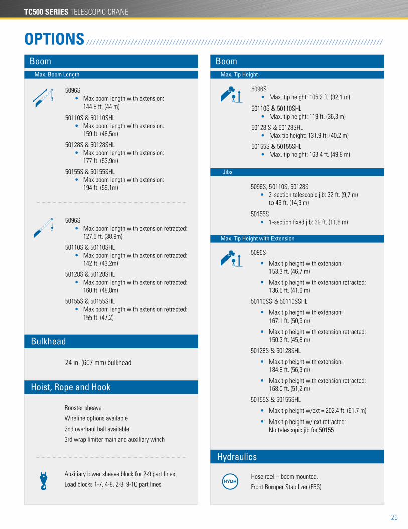
OPTIONSBoom
5096S • Max boom length with extension: 144.5 ft. (44 m)
50110S & 50110SHL • Max boom length with extension: 159 ft. (48,5m)
50128S & 50128SHL • Max boom length with extension: 177 ft. (53,9m)
50155S & 50155SHL • Max boom length with extension: 194 ft. (59,1m)
5096S • Max boom length with extension retracted: 127.5 ft. (38,9m)
50110S & 50110SHL • Max boom length with extension retracted: 142 ft. (43,2m)
50128S & 50128SHL • Max boom length with extension retracted: 160 ft. (48,8m)
50155S & 50155SHL • Max boom length with extension retracted: 155 ft. (47,2)
Max. Boom Length
Auxiliary lower sheave block for 2-9 part lines
Load blocks 1-7, 4-8, 2-8, 9-10 part lines
/ / / / / / / / / / / / / / / / / / / / / / / / / / / / / / / / / / / / / / / / / / / / / / / / / / / / / / / / / / / / / / / / / / / / / / / / / / / / / / / / / / / / / / / / / / / / /
24 in. (607 mm) bulkhead
Boom
5096S
• Max tip height with extension: 153.3 ft. (46,7 m)
• Max tip height with extension retracted: 136.5 ft. (41,6 m)
50110SS & 50110SSHL
• Max tip height with extension: 167.1 ft. (50,9 m)
• Max tip height with extension retracted: 150.3 ft. (45,8 m)
50128S & 50128SHL
• Max tip height with extension: 184.8 ft. (56,3 m)
• Max tip height with extension retracted: 168.0 ft. (51,2 m)
50155S & 50155SHL
• Max tip height w/ext = 202.4 ft. (61,7 m)
• Max tip height w/ ext retracted: No telescopic jib for 50155
Max. Tip Height
Max. Tip Height with Extension
5096S, 50110S, 50128S • 2-section telescopic jib: 32 ft. (9,7 m) to 49 ft. (14,9 m)
50155S • 1-section fixed jib: 39 ft. (11,8 m)
Jibs
5096S • Max. tip height: 105.2 ft. (32,1 m)
50110S & 50110SHL • Max. tip height: 119 ft. (36,3 m)
50128 S & 50128SHL • Max tip height: 131.9 ft. (40,2 m)
50155S & 50155SHL • Max. tip height: 163.4 ft. (49,8 m)
Rooster sheave
Wireline options available
2nd overhaul ball available
3rd wrap limiter main and auxiliary winch
Hoist, Rope and Hook
Bulkhead
Hose reel – boom mounted.
Front Bumper Stabilizer (FBS)
Hydraulics
27
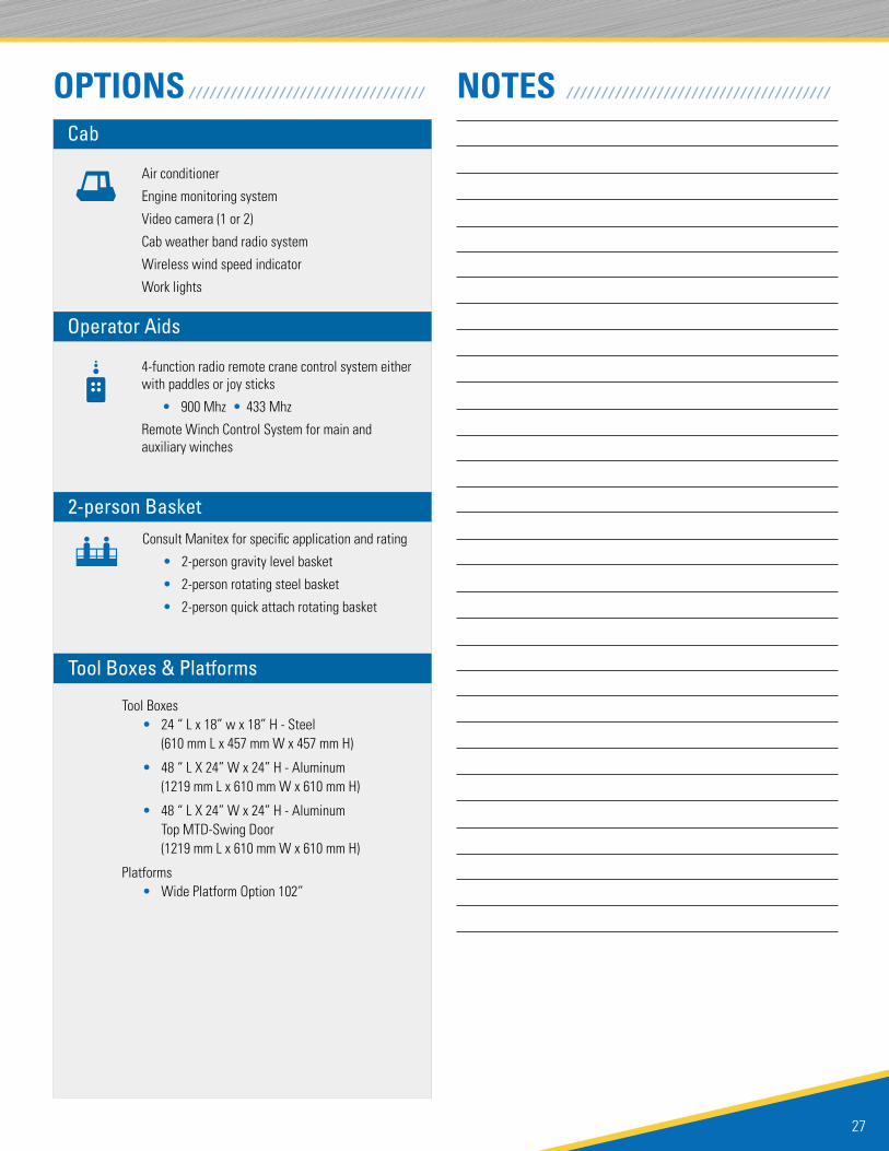
OPTIONS NOTES
Tool Boxes • 24 “ L x 18” w x 18” H - Steel (610 mm L x 457 mm W x 457 mm H)
• 48 “ L X 24” W x 24” H - Aluminum (1219 mm L x 610 mm W x 610 mm H)
• 48 “ L X 24” W x 24” H - Aluminum Top MTD-Swing Door (1219 mm L x 610 mm W x 610 mm H)
Platforms • Wide Platform Option 102”
4-function radio remote crane control system either with paddles or joy sticks
• 900 Mhz • 433 Mhz
Remote Winch Control System for main and auxiliary winches
Consult Manitex for specific application and rating
• 2-person gravity level basket
• 2-person rotating steel basket
• 2-person quick attach rotating basket
Air conditioner
Engine monitoring system
Video camera (1 or 2)
Cab weather band radio system
Wireless wind speed indicator
Work lights
/ / / / / / / / / / / / / / / / / / / / / / / / / / / / / / / / / / / / / / / / / / / / / / / / / / / / / / / / / / / / / / / / / / / / / / / /
Cab
Operator Aids
2-person Basket
Tool Boxes & Platforms
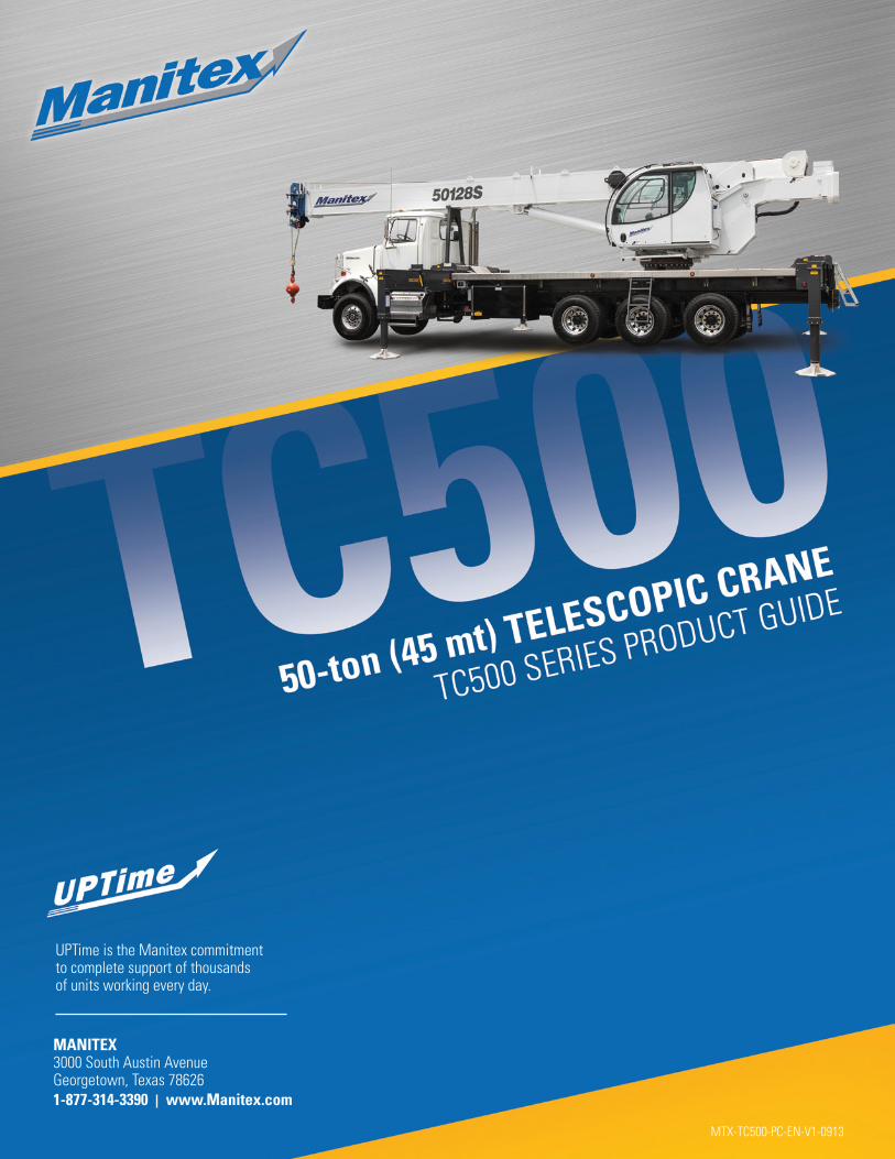
UPTime is the Manitex commitment to complete support of thousands of units working every day.
MANITEX 3000 South Austin Avenue Georgetown, Texas 786261-877-314-3390 www.Manitex.com
MTX-TC500-PC-EN-V1-0913