
Telephone Speech Quality Standards for IP Phone Terminals
16
Telephone Speech Quality Standards for IP Phone Terminals (handsets) CES-Q003-2 September 30, 2004 Communications and Information Network Association of Japan (CIAJ)
Transcript of Telephone Speech Quality Standards for IP Phone Terminals

Telephone Speech Quality Standards
for
IP Phone Terminals (handsets)
CES-Q003-2
September 30, 2004
Communications and Information Network Association of Japan (CIAJ)

Table of contents
Introduction.........................................................................................................................3 1. Scope of application.........................................................................................................5
1.2 Interfaces ...................................................................................................................5 1.3 Principles for specified values...................................................................................7
2. Normative references ......................................................................................................7 3. Send speech characteristics ............................................................................................7
3.1. Send loudness rating (SLR)......................................................................................7 3.2. Send frequency response ..........................................................................................7 3.3 Send noise ..................................................................................................................9
4. Receive speech characteristics........................................................................................9 4.1 Receive loudness rating (RLR) ..................................................................................9 4.2. Receive frequency response......................................................................................9 4.4. Receive noise ...........................................................................................................10
5. Sidetone characteristics ................................................................................................10 5.1. Sidetone masking rating (STMR) ..........................................................................10
6. Return from receive to send.......................................................................................... 11 6.1. Weighted Terminal coupling loss and echo return loss......................................... 11 6.2. Echo canceller and non-linear processing.............................................................. 11
7. Terminal voice latency .................................................................................................. 11 7.1 Network performance objectives .............................................................................12 7.2 Terminal voice latency.............................................................................................12
8. Overall speech quality...................................................................................................14 8.1 Requirement ............................................................................................................14 8.2 Calculation of the R Value.......................................................................................15
Introduction [Objectives for establishing these Standards] It is the responsibility of manufacturers or service providers in the information and communication network industry to give users clear information about the speech quality performance of the devices or services they provide. For this reason, when the provision of communication terminals was deregulated more than ten years ago, the Communications and Information Network Association of Japan (CIAJ) established the speech quality standards for “Standard Telephones and Multi-functional Telephones”, and began to provide a compliance test and certification service for speech devices. Manufacturers and vendors have displayed the “C” mark on compliant products as proof of satisfactory speech quality performance for users. CIAJ drafted the speech quality standards for “Digital Cordless and Mobile Phones” in 2001 and released it to CIAJ members in the hope of early adoption. Recently, as the speeds of both Internet access connections and terminals have become faster, IP phones are beginning to be widely used. Although the IP phone service has the advantages of being more economical and more compatible with multimedia than the conventional telephone service based on circuit-switching, it is also reported to pose new problems for speech quality. The CIAJ Telecommunications Quality Committee formed a Working Group to study the speech quality problems associated with providing telephone service using VoIP and to develop speech quality standards for such a service. In order that the standards so developed might be widely accepted by CIAJ member companies, it was necessary to make the standards reasonably achievable with currently available technology. Therefore, the WG surveyed the current situation by conducting two rounds of speech quality tests, mainly using products from member companies as samples. In 2002, in order to promote the use of VoIP over public networks, the Ministry of Internal Affairs and Communications decided to permit telecommunications providers and IP service providers to assign the “050” telephone number prefix to their VoIP phone services if their service applications show that their services satisfy a certain level of speech quality. Consequently, the Ministry requested the Telecommunication Technology Committee (TTC) to develop a requirement for the measurement of the speech quality of IP phones. The TTC developed a provisional requirement in September 2002. Since the Ministry’s intention was to use the requirement for compliance testing of network quality, the specification
3

used a hypothetical reference terminal (the default value in ITU-T Rec. G.107) as the telephone terminal. In the International Telecommunications Union - Telecommunication Standardization Sector (ITU-T), Study Group 12 had been studying the speech quality of VoIP and a draft recommendation, P.VoIP, concerning terminals to be used for VoIP was proposed in its May 2002 meeting. In addition to these activities, the European Telecommunications Standards Institute (ETSI) and the Telecommunications Industry Association (TIA) in the U.S. are also standardizing VoIP service quality. Taking these activities in various standardization organizations into consideration, CIAJ have established the “Telephone Speech Quality Standards for IP Phone Terminals” as follows. [Notes on the Standards] These Standards were developed by referring to ITU-T draft Rec. P.VoIP (May 2002). Although this Recommendation is applicable to three types of terminals (handsets, headsets, and hands-free sets), the scope of application of the CIAJ Standards has been limited to handsets, on account of the urgency of the need to issue standards and taking into consideration the degree of penetration of different terminals, and have left the standards for other types of terminals for further study. Among the items specified in the ITU-T Recommendation, receive comfort noise, maximum acoustic pressure, input/output linearity, distortion ratio and stability loss have been classified as items for further study by the CIAJ Telecommunications Quality Committee because the Committee was unable to determine the applicability of these items in the ITU-T Recommendation due to the insufficient time spent on study within the Committee and on the survey of CIAJ members’ products. Although these Standards address terminals, some items may be affected by the conditions of the IP network used. To cope with such network factors, end-to-end quality has been specified while setting several sets of typical conditions on the network. The Standards refer to the R- value and MOS value on the E- Model, which are needed for the specification, and also touch on speech quality degradation resulting from speech signal processing. Since the study of such items is still ongoing in ITU-T, they are also left as items for further study in these
4

Standards.
[Use of the Standards] At present, a compliance mark (the so-called “C Mark”) is defined for “CES-Q001” Standards for analog telephones. The application of a similar mark for the present Standards is being considered with the aim of having it adopted one year after the initial publication of the Standards. The items studied include the application procedure, the operational procedure for examination and certification, and the procedure for receiving and reviewing any requests by CIAJ members for modifications to the standards. [Revision of the Standards] After the Standards were established, they were applied only internally for one year. As a result, it has been decided to make the following minor revisions. To increase compatibility with standards in other countries, some requirements have been relaxed. In particular, the requirements for sending and receive loudness rating and sidetone masking rating have been relaxed. The requirement for receive sound level adjustment range has been deleted. The relaxation of the R- value for asymmetric connections has been applied to symmetric connections as well. In this revision、
some corrections have also been made to clarify descriptions and errors. The TELR requirement has been modified. Delay variation and packet arriving out of sequence have been added to the network . performance. The description about average terminal voice latency and the average delay time over an IP network have been added. A part of requirement for the R- value (G.729) has been changed. 1. Scope of application 1.1 Devices to which the Standards are to be applied IP phone terminals and PC soft phones with handsets (300–3400Hz band); VoIP gateways using analog telephones as their terminals. 1.2 Interfaces
On the phone terminal side, the acoustic interfaces are the mouthpiece and earpiece of the handset, and the electrical interface is FXS with the DC current supply to the phone terminal. On the other hand at the network side, the interface is
5

Ethernet (IEEE802.3)、 digital signal is converted into analog by using reference codec.
Acoustic Electrical
connection point connection point
Send Send
Handset CODEC Signal Ethernet
processing interface
Receive Receive
IP phone type
USB handset, etc. PC, etc.
Send Send
AUDIO Signal Ethernet
interface processing interface Receive Receive
PC soft phone type
Analog phone VoIP TA, etc.
Send Send Analog
Handset CODEC Signal Ethernet telephone SLIC processing interface
Receive circuit Receive
Gateway type
6

1.3 Principles for specified values Standard values are design target values not taking the variance of products into consideration. 2. Normative references The standard from which these Standards have been derived is:
ITU-T draft Recommendation P.VoIP (May 2002)
Regarding the R Value: ITU-T Recs.G.107, G.108, G.109 and G.113 TTC Standard JJ-201.01
Regarding MOS: ITU-T Recs. P.800, P.830, P.833, P.862 and P.834
Regarding echo
ITU-T Recs. G.122 and G.131
Regarding echo cancellers ITU-T Recs. G.165 and P.167
Regarding loudness rating ITU-T Recs. P.48, P.64 and P.79
3. Send speech characteristics 3.1. Send loudness rating (SLR) The send loudness rating (SLR) shall be 8±4dB. The measurement shall be made in accordance with CES-Q003M-001 “Measuring method”. If the send sensitivity is variable, the measurement shall be made using the sensitivity recommended by the manufacturer. It is desirable that the physical shape and the dimensions of the handset are close to those defined in ITU-T Rec. P.350. 3.2. Send frequency response
The send frequency response shall be as shown in Table 1 and Figure 1. The measurement shall be made in accordance with CES-Q003M-001 “Measuring method”.
7

Table 1
Frequency(Hz) Upper Limit(dB) Lower Limit(dB)
100 −12 −∞ 200 0 −∞ 300 0 −14
1000 0 −8 2000 4 −8 3000 4 −8 3400 4 −11 4000 0 −∞ 8000 −20 −∞
dB
10
5
0
–5
–10
–15
–20 100 1000 10,000 Hz
Figure 1
Table 1 and Figure 1 define the mask pattern. The measuring frequency points shall be ISO 1/3 octave band central frequencies. These points shall be inside the mask pattern.
8

3.3 Send noise
The send noise shall be -64dBm0p or lower. The measurement shall be made in accordance with CES-Q003M-001 “Measuring method”. Any noise reduction capabilities, such as a noise canceller, an echo canceller or AGC, shall be enabled. If the send sensitivity is variable, the measurement shall be made using the sensitivity recommended by the manufacturer.
4. Receive speech characteristics
4.1 Receive loudness rating (RLR)
The receive loudness rating (RLR) shall be 2±4dB. If a receive sound level setting function is provided, the standard setting shall be selected. If a receive sound level adjustment function is provided, the nominal position shall be selected.
The measurement shall be made in accordance with CES-Q003M-001 “Measuring method”. It is desirable that the physical shape and the dimensions of the handset are close to those defined in ITU-T Rec. P.350.
4.2. Receive frequency response
The receive frequency response shall be as shown in Table 2 and Figure 2. If a receive sound level adjustment function is provided, the nominal position shall be selected. The measurement shall be made in accordance with CES-Q003M-001 “Measuring method”.
Table 2
Frequency(Hz) Upper Limit(dB) Lower Limit(dB)
100 –10 −∞ 200 2 –∞ 300 2 –9 1000 2 –7 2000 2 –7 3000 2 –11 3400 2 –12 4000 2 –∞ 8000 –18 −∞
9
dB 10
5
0
–5
–10
–15
–20 100 1000 10 000 Hz
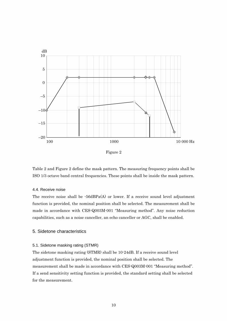
Figure 2 Table 2 and Figure 2 define the mask pattern. The measuring frequency points shall be ISO 1/3 octave band central frequencies. These points shall be inside the mask pattern. 4.4. Receive noise
The receive noise shall be -56dBPa(A) or lower. If a receive sound level adjustment function is provided, the nominal position shall be selected. The measurement shall be made in accordance with CES-Q003M-001 “Measuring method”. Any noise reduction capabilities, such as a noise canceller, an echo canceller or AGC, shall be enabled. 5. Sidetone characteristics 5.1. Sidetone masking rating (STMR)
The sidetone masking rating (STMR) shall be 10-24dB. If a receive sound level adjustment function is provided, the nominal position shall be selected. The measurement shall be made in accordance with CES-Q003M-001 “Measuring method”. If a send sensitivity setting function is provided, the standard setting shall be selected for the measurement.
10

6. Return from receiving to sending The return that causes talker echo is specified as the talker echo loudness rating (TELR). 6.1. Weighted Terminal coupling loss and echo return loss In the case of the IP phone type and the PC soft phone type terminals, since they use four wires, the only coupling that arises is acoustic coupling from the earpiece to the microphone. The acoustic coupling level is expressed as the weighted terminal coupling loss (TCLw). TELR is the sum of the TCLw, SLR and RLR. In the case of the gateway type terminal, both return at the 2-wire to 4-wire conversion circuit and acoustic coupling in the external telephone can arise. The return through the circuit is expressed as the echo return loss (Le). The measurement of Le shall be in accordance with ITU-T Rec. G.122. In general, the return through the circuit is much higher than that due to acoustic coupling, so the latter can be ignored. TELR is the sum of Le, SLR and RLR. (Requirement) The TELR of the IP phone type shall be 62dB or higher at the recommended value of receive sound level adjustment. It shall be 45dB or higher at the maximum sound level. The TELR of the gateway type shall be 62dB or higher. 6.2. Echo canceller and non-linear processing Echo cancellers and echo suppressers with a voice switch are called non-linear processors (NLPs), and are used to suppress the return signals from receive side to the send side. However, these NLPs produces time interruption distortion, and may lead to a impairment in speech quality. Since this speech quality cannot be evaluated by a simple listening test, it is necessary to evaluate it using a conversation test. The requirement for these items is left as items for further study. 7. Terminal voice latency Types of distortion that arise in a VoIP-based telephone service include those
11
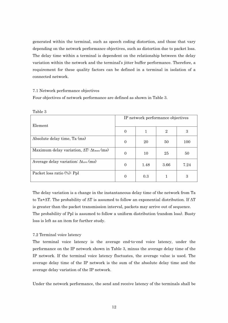
generated within the terminal, such as speech coding distortion, and those that vary depending on the network performance objectives, such as distortion due to packet loss. The delay time within a terminal is dependent on the relationship between the delay variation within the network and the terminal’s jitter buffer performance. Therefore, a requirement for these quality factors can be defined in a terminal in isolation of a connected network. 7.1 Network performance objectives Four objectives of network performance are defined as shown in Table 3. Table 3
IP network performance objectives Element
0 1 2 3 Absolute delay time, Ta (ms) 0 20 50 100
Maximum delay variation, ∆T: ∆tmax (ms) 0 10 25 50
Average delay variation: ∆tave (ms) 0 1.48 3.66 7.24
Packet loss ratio (%): Ppl 0 0.3 1 3
The delay variation is a change in the instantaneous delay time of the network from Ta to Ta+∆T. The probability of ∆T is assumed to follow an exponential distribution. If ∆T is greater than the packet transmission interval, packets may arrive out of sequence. The probability of Ppl is assumed to follow a uniform distribution (random loss). Busty loss is left as an item for further study. 7.2 Terminal voice latency The terminal voice latency is the average end-to-end voice latency, under the performance on the IP network shown in Table 3, minus the average delay time of the IP network. If the terminal voice latency fluctuates, the average value is used. The average delay time of the IP network is the sum of the absolute delay time and the average delay variation of the IP network. Under the network performance, the send and receive latency of the terminals shall be
12

within the ranges shown in Table 4 and Figure 3. Although it is possible to further reduce the latency according to the principle described in G.711, the requirement is provisionally relaxed in consideration of the actual performance of the products available on the market.
Table 4 Performance on an IP network
0 1 2 3
Send latency
≤35 ms
Send latency (Provisional relaxed requirement)
≤55 ms
Receive latency
≤65 ms ≤65 ms ≤65 ms ≤75 ms
Receive latency (Provisional relaxed requirement)
≤95 ms ≤95 ms ≤95 ms ≤115 ms
relaxation Provisional
Network performance
100
Receive latency
40
140
La
te
nc
y(
ms
)
3 2 1 0
80
120
60
Figure 3
13

8. Transmission rating factor In order to quantify the transmission rating factor, the “R Value” defined in ITU-T Rec. P.107 is adopted as the index in this standard. As in Section 7.1, the four objectives of network performance shown in Table 3 are used. 8.1 Requirement (1) In the case of a symmetric network in which the same types of terminals are connected to both sides of an IP network, or in the case where one side of the network is connected to an IRS as defined in ITU-T Rec. P.48, the R Value shall be within the
range shown in Table 5, Figure 4 and Figure 5.*
(2) In the case where different types of terminals are connected, or where one side is the PSTN, the R Value of a terminal side shall be within the range indicated as asymmetric in Table 5, Figure 4 and Figure 5. In the case of an asymmetric network, the terminal type at the other end cannot be fixed. Since it is difficult to optimize operation for all terminal types, the requirement is relaxed. *) For the time being, as a provisional measure taking account of the actual performance of the products available on the market, the relaxed requirement in (2) will be applied even to the case of a symmetric network or the case where one terminal is an IRS. In the case where one side is connected to the PSTN, the performance of the IP-PSTN gateway installed in the PSTN side influences the performance of the IP terminal at the other end. For example, if the echo at the PSTN side is too high, the NLP in an echo canceller installed in the gateway will operate, and this will cause voice to be interrupted at double talk on the IP terminal side, thus impairing speech quality, etc. The requirements of the default gateway and of the NLP within an echo canceller are items for further study.
14
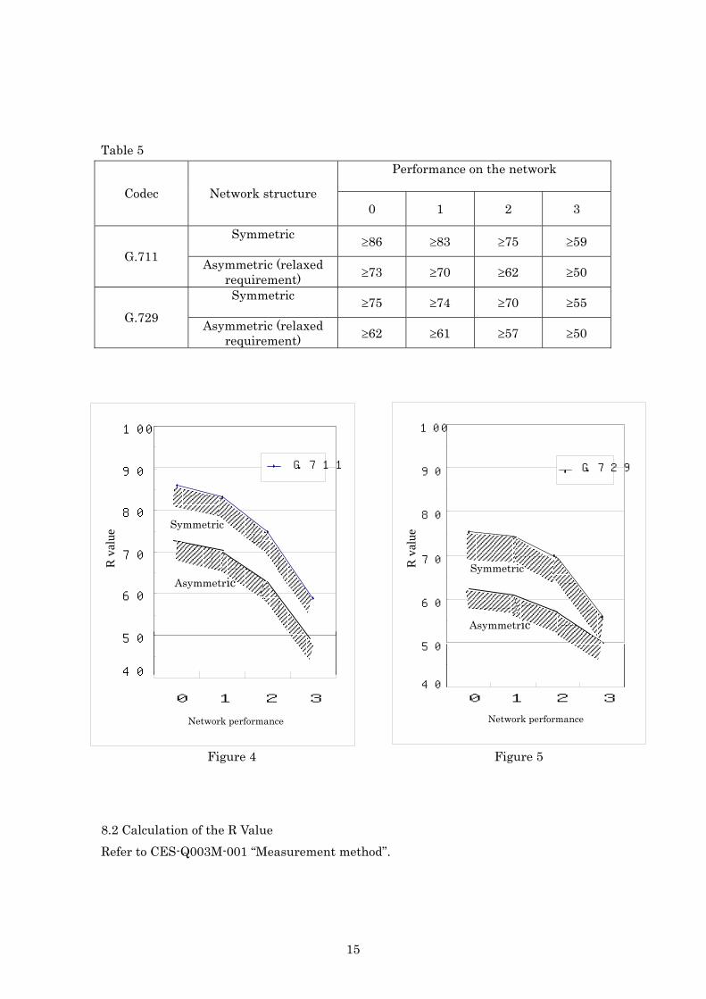
Table 5
Performance on the network
Codec Network structure 0 1 2 3
Symmetric ≥86 ≥83 ≥75 ≥59
G.711 Asymmetric (relaxed requirement) ≥73 ≥70 ≥62 ≥50
Symmetric ≥75 ≥74 ≥70 ≥55
G.729 Asymmetric (relaxed requirement) ≥62 ≥61 ≥57 ≥50
R
val
ue
Asymmetric
Symmetric
40
G.729
Network performance 32 10
100
90
80
70
60
50
R v
alue
Symmetric
Asymmetric
40
G.711
Network performance 3 2 1 0
100
90
80
70
60
50
Figure 4 Figure 5 8.2 Calculation of the R Value Refer to CES-Q003M-001 “Measurement method”.
15

16
Telecommunications Quality Committee Chair Hiroshi Irii Media Solution Headquarters, NTT Advanced
Technology Corporation Vice-Chair Hiroshi Asada Hino Business Communication System Department,
Toshiba PC&Network Working Group on Operation Requirements Chair Yoshimasa Kamogashira Telecommunications Division, Iwatsu Electric
Co., Ltd. Hiroshi Asada Hino Business Communication System
Department, Toshiba PC&Network Hiroshi Irii Media Solution Headquarters, NTT Advanced
Technology Corporation Shinya Suzuki Enterprise Network Division, Hitachi
Communication Technologies, Ltd. Shinji Naito Enterprise System Department, Development
Promotion Division, Nakayo Telecommunications, Inc.
Members
Kiyokazu Ito Telecommunication Systems Engineering Center, Mitsubishi Electric Corporation
Secretary Hirokazu Shimizu Communications and Information Network Association of Japan