Telenursing RoboPuppet - web.wpi.edu · Telenursing RoboPuppet A Major Qualifying Project in...
94
Telenursing RoboPuppet A Major Qualifying Project in Partial Fulfillment of the Degree Requirements for the Bachelors of Science in Mechanical Engineering and Robotics Engineering at Worcester Polytechnic Institute Academic Year 2017-2018 Brent M. Heavey B.S. Robotics Engineering Class of 2018 Matthew M. Lamare B.S. Mechanical Engineering and Robotics Engineering Class of 2018 Evan M. Stelly B.S. Mechanical Engineering Class of 2018 Advisor: Professor Zhi (Jane) Li Submitted on April 26th, 2018
Transcript of Telenursing RoboPuppet - web.wpi.edu · Telenursing RoboPuppet A Major Qualifying Project in...

Telenursing RoboPuppet A Major Qualifying Project in Partial Fulfillment of the Degree Requirements for the Bachelors
of Science in Mechanical Engineering and Robotics Engineering at Worcester Polytechnic
Institute
Academic Year 2017-2018
Brent M. Heavey B.S. Robotics Engineering Class of 2018
Matthew M. Lamare B.S. Mechanical Engineering and Robotics Engineering Class of 2018
Evan M. Stelly B.S. Mechanical Engineering Class of 2018
Advisor: Professor Zhi (Jane) Li
Submitted on April 26th, 2018

Abstract
The Tele-robotic Intelligent Nursing Assistant (TRINA) is a retrofitted Rethink Robotics
Baxter, designed to perform high strain, repetitive tasks for nurses and interact with infectious
patients. Previously, it was found that these tasks were faster for nurses to perform by hand than
to perform by using TRINA. One factor that increased the time needed to complete tasks was the
lack of controller intuitiveness and difficulty of use, based on user feedback. The goal of this
project is to improve TRINA’s ability to perform common nursing tasks by designing an
improved input device. The selected solution was to create a Robopuppet, a DH parameter scale
model of Baxter’s arms, with angle sensors. Based on a method created by researchers at Duke
University, a Robopuppet allows for direct manipulation of Baxter’s joint space with one-to-one
correspondence. Actuators were integrated to provide the opportunity for gravity compensation
and haptic feedback. The puppet was successful in manipulating Baxter’s arms smoothly and
precisely, however, more testing and refinement will be needed to more accurately perform
complete nursing tasks with active feedback.
1

Table of Contents
Abstract 1
Table of Contents 2
Table of Figures 5
Acknowledgements 7
Executive summary 8 Introduction 8 Background 9 Mechanical Design and Analysis 10 Electrical Design and Analysis 10 Control Software Design and Analysis 11 Results and Conclusions 12
Introduction 14
Background 19 Applications 19
Nursing 19 Other Potential Applications 21
Prior Work 22 Robotic Nursing 22 TRINA 23 RoboPuppet 27
Existing Input Devices 28 Puppets 28
Prior Technologies 29 Rethink Robotics Baxter 29 Mechanical Systems 31 Mechatronic Systems 33 Software Systems 36
Mechanical Design and Analysis 38 Duke Arm Design 38 Passive Robopuppet Redesign 41
2
Analysis of Passive Version 44 Active RoboPuppet Model 45
Actuator Selection 46 Preliminary Hand Design 49 Button Design 50 Manufacturing 51
Electrical Engineering Design and Analysis 55 Arm Angle Sensing 55
Passive RoboPuppet Arm Angle Sensing 55 Active Puppet Arm Angle Sensing 60
Actuator Signal Driving 64 Supply Rail 64 Microcontroller Signal 65
Wiring and Wire Management 66 Microcontroller Selection 68 Dead Man Switch 70
Software and Control Design and Analysis 71 High Level Overview 71 Passive RoboPuppet Software Architecture 72 Active RoboPuppet Software Architecture 73 Gravity Compensation Controller Policy 74 Haptic Control Scheme 75
Conclusions 77 Testing 77 Performance 78 Durability and Reliability 78 Cost 79 Continuation 79
References 81
Appendix I: Troubleshooting Guide 83
Appendix II: Bringup Instructions 85 For Simulated Robot: 85 For Physical Robot: 86
Appendix III: CAD Models 87
3

Passive RoboPuppet CAD Models 87 Active RoboPuppet CAD Models 89
Appendix IV: Torque Calculations 93
4
Table of Figures
2.1: TRINA System from Duke University (Hauser et al, n.d.)
2.2: Control Station for Duke’s TRINA System (Hauser et al, n.d.)
2.3: Baxter Hardware Configuration (Rethink Robotics, 2015)
2.4: Baxter Performing Pick-and-Place Manipulation Tasks (Hull, 2017)
2.5: Overview of TRINA Software Stack
3.1: Solidworks Rendering of Duke Designed RoboPuppet
3.2: Complete Duke Designed RoboPuppet Assembly
3.3: Universal Joint Assembly for Duke Designed RoboPuppet
3.4: Passive Model CAD
3.5: Assembled Passive Model
3.6: Result of Potentiometer Housing Failure
3.7: Exploded view of Joint W0 for passive RoboPuppet
3.8: Pincher Gripper Control
3.9: Pincher Gripper Control
4.1: Potentiometer
4.2: Calibration Fixture
4.3: Isolated Potentiometer Calibration Data
4.4: Zero Positions and Joint Limits for “Bend Joints” (Rethink Robotics, 2015)
4.5: Zero Positions and Joint Limits for “Twist Joints” (Rethink Robotics, 2015)
4.6: Testing setup for hall effect encoders
5

4.7: Mounting of Hall Effect Encoder on S1 Joint
4.8: Mounting of Hall Effect Encoder on S0 Joint
4.9: Motor wire management on active
4.10 Teensy 3.6 Connected to a Breadboard
5.1: TRINA Stack Process
5.2: Active RoboPuppet Software Strategy
6
Acknowledgements
We would like to collectively thank a number of individuals who offered their time and
resources to help ensure the success of the project:
Professor Jane Li, Project Advisor
Kevin Harrington, Robotics Teaching Lab Manager
Ken Stafford, Teaching Professor of Robotics and Mechanical Engineering
Loris Fichera, Associate Professor of Robotics Engineering and Computer Science
Doctor Erica Stults, Application Scientist
Nathaniel Goldfarb, HIRO Lab Researcher
Gunnar Horve, HIRO Lab Researcher
Ozan Akyildiz, HIRO Lab Researcher
Sihui Li, HIRO Lab Researcher
Ian Anderson, Washburn Shops Manager
James Loiselle, Washburn Shops Manager
In addition we would like to thank the numerous students, faculty and staff who have provided
feedback, attended presentations, or otherwise made small contributions that helped accomplish
the aims of this project
7
Executive summary
Introduction
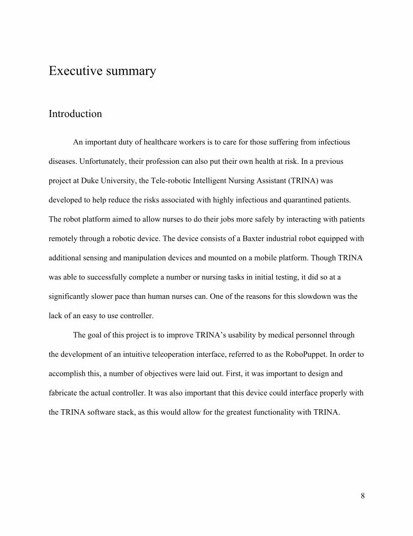
An important duty of healthcare workers is to care for those suffering from infectious
diseases. Unfortunately, their profession can also put their own health at risk. In a previous
project at Duke University, the Tele-robotic Intelligent Nursing Assistant (TRINA) was
developed to help reduce the risks associated with highly infectious and quarantined patients.
The robot platform aimed to allow nurses to do their jobs more safely by interacting with patients
remotely through a robotic device. The device consists of a Baxter industrial robot equipped with
additional sensing and manipulation devices and mounted on a mobile platform. Though TRINA
was able to successfully complete a number or nursing tasks in initial testing, it did so at a
significantly slower pace than human nurses can. One of the reasons for this slowdown was the
lack of an easy to use controller.
The goal of this project is to improve TRINA’s usability by medical personnel through
the development of an intuitive teleoperation interface, referred to as the RoboPuppet. In order to
accomplish this, a number of objectives were laid out. First, it was important to design and
fabricate the actual controller. It was also important that this device could interface properly with
the TRINA software stack, as this would allow for the greatest functionality with TRINA.
8

Background
The basic process of creating a RoboPuppet begins with finding a CAD model of the
desired robot. The robot joints are inspected, then a watertight mesh is created from the CAD and
scaled to the desired size. From here, the necessary pocket geometries are created in order for the
potentiometer assemblies to fit inside the puppet. Then the puppet parts are printed and
assembled, including the potentiometer assemblies. Lastly wires are connected and the system is
tested. The designers recommend printing the parts with PLA or ABS plastic and building the
potentiometer assemblies by soldering wires together. Hot glue is used to hold the potentiometer
knob against the joint that will be turning it. (Hauser et al, n.d)
The existing controller for TRINA was the Geomagic Touch Haptic Device. This device
is a link based haptic controller that can provide force feedback to users when working with
computer programs such as medical training programs or digital sculpting programs. It is also
used as a controller for research and development projects in fields from military work to
biomedical work (Qin et. al, 2015). The major disadvantages of this device are its reduced
workspace and degrees of freedom compared to TRINA.
The largest component of TRINA, and the one that this project was most focused on was
the Rethink Robotics Baxter industrial robot. Originally designed to safely operate in the vicinity
of human workers, Baxter’s design consists of two 7-DOF arms with series elastic actuators and
a torsional spring in series to reduce shock loads and add compliance (Pratt, Williamson, 1995).
This, as well as a number of other safety conscious features, make Baxter an excellent choice for
working in a confined space with humans.
9

Mechanical Design and Analysis
Mechanically, this project focused on designing and fabricating an intuitive input device
for TRINA in the form of a RoboPuppet. Initially, a prototype of a RoboPuppet for Baxter
designed by researchers at Duke University was constructed for testing and analysis. Over the
course of the project, two additional prototypes were developed to accomplish this goal, the
passive design, which improves upon the robustness of the originally design, and the active
design, which incorporates motors into the design to allow for gravity compensation and haptic
feedback. The two major focuses of the design were increasing structural stability and
maintaining Denavit-Hartenberg (DH) parameters that are identical to the Baxter industrial robot.
Both RoboPuppets were fabricated with additive manufacturing (commonly referred to as
3D printing) and were designed using an iterative process. The rapidity and low cost of 3D
printing allowed a number of prototypes to be manufactured to test. This proved especially
useful in working with the tight tolerances for many of the joints.
Electrical Design and Analysis
For the passive RoboPuppet, the joint angle sensors are 270 degree analog
potentiometers. These are connected to the microcontroller, in this case an Arduino Mega, via a
breadboard. The potentiometer required calibration which was done both before they were
connected to the RoboPuppet to ensure linearity and after they had been connected to ensure that
the microcontroller was able to accurately calculate the position of the joints.
10

For the active RoboPuppet, the potentiometers were replaced with hall effect absolute
encoders for joint angle sensing. Despite a cost increase, there were several key reasons for the
change, including increased resolution, mechanical simplicity, and the ability to use an I2C
connection. These sensors connect to a Teensy 3.6 microcontroller that was chosen for its
compact size, processing power, and multiple I2C busses. In addition, the active RoboPuppet
incorporates motors into the design. The chosen motors are continuous rotation servos that are
capable of being controller purely by input voltage as well as by an input signal.
Control Software Design and Analysis
The software for the RoboPuppet controller is split into two major sections: the Python
code running on the PC and the C++ code running on the microcontroller. For the passive
RoboPuppet, the microcontroller calculates the current joint angles and transmits them to the PC
over a USB UART connection. The Python code is tasked with receiving this data and passing it
into the TRINA stack, which in turn controls the physical or simulated TRINA robot.
For the active RoboPuppet, the software will operate in a similar manner, but will include
the ability to send feedback from the robot to the microcontroller. This feedback, in the form of
the current joint angles of the robot, is used to determine the torque desired for haptic feedback.
The active RoboPuppet will also implement gravity compensation, with the motor torque
calculations being done by the microcontroller.
11
Results and Conclusions
In general, the passive RoboPuppet was successful in controlling the robot, with some
limiting factors. The RoboPuppet was able to accurately position the robot, however, the
TRINA’s slow operating speed meant that the RoboPuppet often became far out of sync with the
physical robot. The RoboPuppet’s workspace was slightly larger than the actual robot’s, allowing
it to utilize the entire workspace of TRINA. Though this generally made controlling the robot
fairly easy it also allowed the user to position the RoboPuppet in a collision position or an
otherwise unreachable pose. For the most part, however, these situations could be prevented by
configuring the TRINA stack to only allow safe positions. The foot pedal system used to engage
and disengage the RoboPuppet was also successfully implemented.
Despite this project’s successes, there is still room for continuation. First and foremost is
the completion of the active RoboPuppet. Though the hardware design has progressed to a usable
state, and an arm has been constructed, there is still some refinement to be done on the design.
One particular area of concern is the workspace of the RoboPuppet. Though it would likely still
be sufficient to operate TRINA, the workspace is smaller than the actual robot. This could likely
be improved by removing unnecessary material near the joints as well as other minor design
improvements. A further step would be to implement the software for the active RoboPuppet,
including gravity compensation and haptic feedback. Additional testing as well as work on the
grippers will also be necessary going forward.
12

13

Introduction
An important duty of healthcare workers, such as nurses, is to care for those suffering
from infectious diseases. Unfortunately, their profession can also put their own health at risk.
The CDC reported that “the incidence rate of injuries and illnesses per 100 full time workers
employed in nursing and personal care facilities is 13.5,” compared to the national average of
1.8. These risks come from a variety of areas, from exposure to blood and bodily fluids through
sprays, splashes and pinpricks with infected needles to ergonomic injuries from repetitive tasks
like lifting (CDC, 2011). In short, nursing in an inherently dangerous profession, subjecting
employees to a variety of risks, from dirty tasks that expose nurses to potentially dangerous
bodily fluids, to dull jobs with repetitive tasks that can cause muscle injuries. As such, a robotic
nursing platform would be a prudent choice option.
In a previous project at Duke University, the Tele-robotic Intelligent Nursing Assistant
(TRINA) was developed to help reduce the risks associated with highly infectious and
quarantined patients. The robot platform aimed to allow nurses to do their jobs more safely by
interacting with patients remotely through a robotic device. The device consists of a Baxter
industrial robot mounted on a mobile platform. The end effectors have been equipped with Right
Hand Robotics brand pneumatic grippers. TRINA was designed to complete 26 common nursing
tasks, split into 71 subtasks. These tasks were completed by using Baxter’s 7 degree of freedom
(DOF) arms to manipulate objects such as needles and iv bags in order to carry out a nurse's
duties. (Hauser et al, 2015)
14

After testing it was found that TRINA was able to complete 52 of the 71 subtasks.
However, TRINA did so at an average rate of about 95 times slower than a nurse unassisted by
TRINA. This is due, in part, to the method nurses used to operate TRINA. During the trials user
described difficulty using TRINA due to a lack of precise orientation control. Additionally,
some testers described issues with “understanding the robot’s combined position/orientation
workspace, in particular joint limits and inverse kinematics singularities” and the
“determination of a contact state change due to a lack of tactile sensation”.(Hauser et al, 2015)
These complaints are all linked to the usability of TRINA’s teleoperation interface.
Our goal is to improve TRINA’s usability by medical personnel through the
development of an intuitive teleoperation interface, referred to as the RoboPuppet. Specifically,
this controller will consist of two arms, similar to the ones used by TRINA. Specifically, this
controller will consist of two arms, similar to the ones used by TRINA. From this goal,
objectives were developed that to help evaluate the final product. These objectives were
organized by topic as Mechanical, Mechatronic, and Software.
Mechanical Objectives:
A major mechanical objective is the development of an input device for TRINA with the
same general geometries and capabilities as TRINA itself. This means the controller should have
7 DOF and a control method for TRINA’s grippers, features that most traditional input devices
do not include. In addition, our RoboPuppet requires a method of preventing unintentional input
to TRINA. This will allow the user to let go of the input device periodically without
15

involuntarily moving the robot. This improves TRINA’s usability, while also making it safer to
operate by preventing mistakes from accidental movement.
The RoboPuppet should also be designed to allow cables to be routed internally as often
as possible.This will improve the wire management and aesthetics of the RoboPuppet by storing
the cables inside of the device were they cannot be seen and are less likely to be tangled.
Given additional time, an adjustable base should be developed for the input device. This
would allow users to reorient the RoboPuppet in order to place the device at a more comfortable
height and orientation, reducing fatigue and increasing ease of use. Ergonomics is a key design
consideration,ensuring that a user can operate the RoboPuppet without discomfort. However, the
initial priority is a feasibility study of the controller, and the device height and orientation and be
adjusted by adjusting the surface it rests on.
Mechatronic:
In the Mechatronics category, there are two main objectives. The first objective is the
selection of a sensor for measuring the joint movement of the RoboPuppet must be selected.
This sensor should be able to accurately measure the position of the RoboPuppet joints for
TRINA’s full range of motion. The sensor must also be able to easily fit into the input device’s
structure, as the input device will be compact.
The second objective will be selecting which actuators, if any, will be used on the
RoboPuppet. These actuators would provide a means for gravity compensation and haptic
feedback. This selection will be made based on the ratio of the actuator size to the provided
torque, as well as on the cost of the actuator and its ability to be moved by the user without being
16
powered. Additional features that the motors/servos may have, such as built-in potentiometers or
encoders, will also be considered.
Software:
For software, the major objective is to program the RoboPuppet to interface with TRINA
in a way that is compatible with the current TRINA architecture.
If time is available, the RoboPuppet would also be able to run with the manufacturer
supported Baxter SDK for Robot Operating System (ROS). This would necessitate abandoning
the TRINA architecture, but would allow more researchers to integrate this system into their own
projects.
Partially autonomization of TRINA is being considered as a reach objective. Completing
this objective would allow TRINA to complete certain actions or entire subtasks without user
input, or with very limited input. The first focus of automation would be the picking up of
objects that are near the gripper.
Evaluation
To achieve these objectives, two prototypes were developed. A passive model was made
to measure the RoboPuppet position and control TRINA. However, this RoboPuppet has no
haptic feedback. The second model, referred to as the Active RoboPuppet, uses actuators to
provide the user feedback based on the correlation between the puppet position and TRINA’s
true position, in addition to positionally controlling TRINA. A discussion of the development
and performance of these devices can be seen in below sections.
17

18
Background
This section is an overview of the various topics necessary to understanding the
motivations behind the goal of this project, as well as the decisions made during the design
process. Specifically, the topics discussed will be: potential applications of the Telenursing
Robotic Intelligent Nursing Assistant (TRINA), prior experiments with robotic nursing, the
Rethink Robotics “Baxter” platform, and the components used in the final product.
Applications
To better understand the needs of potential users, a study into current and potential
applications of teleoperated humanoid robots was conducted. This study focused on nursing, as
this is the task that the project is primarily concerned with, but also explored other areas.
Nursing
Though an intuitive controller for Baxter has applications in many fields, the one that this
project is primarily interested in is nursing. As such, it is important to understand the duties of a
nurse, the skills required to complete them, and the technology that nurses already have at their
disposal.
Nurses work in a variety of healthcare environments, which range from hospitals to
elderly homes to in-home care. The exact nursing tasks performed depend on the type of nurse
and the situation they are currently working in. However, in general, the nursing process begins
19

with assessing the patient. This assessment is then used to develop a care plan, which is executed
by the nurse, and adapted as necessary over time. (American Nurses Association, n.d)
Evaluating and caring for patients involves nurses completing a number of physical tasks.
This ranges from taking patient vitals, like blood pressure and temperature, to cleaning the
patient’s room and assisting in daily care activities, like helping the patient acquire and eat
meals. (Nurse Journal, n.d) These tasks are repetitive, potentially expose the nurses to contagious
patients, and could potentially be completed by TRINA.
However, there is also a large amount of work involving person to person discussion and
human judgement, such as assembling medical histories, observing patient concerns and making
healthcare decisions based on patient information.(Nurse Journal, n.d) These types of tasks often
rely on the nurse having the ability to interact with the patient, and cannot currently be attempted
by TRINA. As such, they are beyond the consideration of this project, but worthwhile to note
nonetheless.
The physical tasks conducted by nurses were used by researchers at Duke University to
develop the 26 tasks which were used in the design and evaluation of TRINA. However, it is also
important to note that there are other medical workers who are put at risk by working with
infectious patients. Although TRINA was designed with nurses in mind, it is possible that
TRINA can complete tasks for other types of medical professionals as well.
20
Other Potential Applications
Although TRINA is designed as a telepresence nursing robot, a teleoperation interface for
Baxter could be useful in many fields. Telepresence robots have a number of applications, from
allowing families to communicate and assist the elderly from far away locations, to helping
businessmen commute remotely. Robots designed for these purposes are explored below.
Chores, such as cleaning and vacuuming, are frequently a part of everyday life and are
often necessary for healthy living. These tasks, however, are often seen as tedious and time
consuming. In addition, as people get older, these tasks can become too difficult to do without
assistance. In order to help with this problem, companies are developing a variety of devices to
help out with day to day activities. Examples range from home vacuum robots to grill cleaning
robots and self cleaning litter boxes. (Tedeschi, 2014) Most of these devices are designed for
only one or two applications, however, a robot like Baxter has the versatility to complete a
number of these tasks. An intuitive input device for Baxter could allow caretakers to complete a
number of these chores for someone incapable of doing so, saving the time and cost of having
the caretaker travel to the home. In this type of scenario, Baxter would be serving a role similar
to devices such as Toyota’s human support robot (HSR), which are designed to accomplish a
more general list of tasks, like a human helper could. The HSR achieves this with a mobile base
and a gripper capable of retrieving a variety of objects, based on the user’s needs. It also has a
screen in order to telecommunicate with friends and family (Toyota Motors, n.d). Robots like
this have the potential to ease the burden on those who struggle with typical daily activities, such
as the sick or elderly.
21

Prior Work
Robotic Nursing
The wide variety of nursing tasks means that there are a wide variety of robots being
developed to help make their jobs easier. These robots vary from those focused on helping with
mechanical tasks to those focused on making patient interaction easier.
For example, some robots are being developed to help solve logistical problems for
hospitals, such as understaffing. At UCLA, simple telepresence systems are being developed to
allow nurses to look after patients without being in the same room, meaning that nurses can
simply switch from robot to robot, rather than walking from room to room. These robots were
strictly for telecommunication and operated by joystick. The robots consist of a monitor and a
mobile base, with no method of physically interacting with a patient’s room. (Vespa et. al, 2007)
Robots that focus on mechanical tasks allow nurses to do work in a patient’s room while
still being physically isolated from the patient. TRINA is a good example of a robot trying to
accomplish these types of tasks, such as delivering trays and replacing IV bags. There are also
robots, such as the Intellifill, which assists nurses by preparing IV fluid and syringes. A robot
like this is beneficial to hospitals because the work can be completely much more efficiently
with a robot. In addition, the process is safer than preparing the supplies by hand, as there is a
smaller chance of error when mixing compounds or labeling syringes. This type of robot
operates semi-autonomously, initially taking user input, then completing the syringe fluid
preparation automatically (Albritton, 2007). Perhaps most importantly, these types of systems
22

remove a human nurse from the room, allowing them to spend time on other tasks or reduce their
exposure to pathogens.
Research is also being conducted on robots that can care for patients more directly and
even provide emotional support if needed. A good example of this is the PEARL nursebot, being
developed to care for the elderly. Rather than carry out specific activities itself, PEARL is able to
record patient schedules and remind them to perform certain tasks. It is also equipped with
sensors to help it tell when the patient is not performing the tasks and is able to encourage the
patient to keep up with the schedule (Pollack, et. al, 2002). Robots like this help mind patients so
that nurses can spend more of their time on tasks that require their expertise.
Tele-nursing doesn’t always involve using machines to complete tasks and manipulate
objects. There are some systems being developed to help nurses simply survey the rooms of
multiple patients at the same time. For example, a tele-ICU system is being developed to help
supervise patients in intensive care units where nurses can’t be everywhere at once. In this case,
the tele-nursing system consists of a set of cameras surveying the room and an alert button, to
allow staff to bring a nurse’s attention to a specific room, if needed. In addition, the operator has
a workstation that has patient information and waveforms available if needed. In this way,
telenursing robot’s not only help keep nurses safe, but also allow them to deal with multiple
patients without having to change rooms. (Goran, 2010)
TRINA
In the wake of the West African Ebola epidemic of 2013-2015, researchers at Duke
University looked for a way to reduce the risk of nurses becoming infected when working around
23

patients with contagious diseases. Their work eventually led to the creation of the Telenursing
Robotic Intelligent Nursing Assistant (TRINA), a Rethink Robotics Baxter industrial robot
equipped with additional sensing and actuation abilities and mounted on a mobile base. Figure
2.1 shows the example of the TRINA system from Duke University.
Figure 2.1: TRINA System from Duke University (Hauser et al, n.d.)
This type of research is important because healthcare workers are often the ones most
exposed to these diseases, and thus the ones most at risk of catching them. During the outbreak
in Guinea during 2014-2015, the risk of infection for health care workers was 42 times higher
than the general population (Grinnel et. al, 2015). Though the technology did not exist during the
2013-2015 outbreak, robots and telepresence systems offer the potential to remove healthcare
workers from the immediate vicinity of the patients. Preventing even a handful of these
24
individuals from potential exposure to ebola would no doubt have saved lives. Robots are
unaffected by biological pathogens or viruses, and would be able to perform the nursing tasks
unimpeded. Unfortunately, however, the type of robust, high degree of freedom (DOF),
kinematic manipulators required to complete these nursing tasks are difficult to control
autonomously. Furthermore, a robot’s ability to make sense of tasks stated in human vernacular
is still an open ended problem in artificial intelligence. Based on these issues, it was decided that
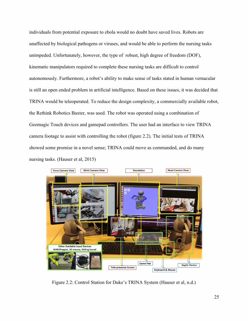
TRINA would be teleoperated. To reduce the design complexity, a commercially available robot,
the Rethink Robotics Baxter, was used. The robot was operated using a combination of
Geomagic Touch devices and gamepad controllers. The user had an interface to view TRINA
camera footage to assist with controlling the robot (figure 2.2). The initial tests of TRINA
showed some promise in a novel sense; TRINA could move as commanded, and do many
nursing tasks. (Hauser et al, 2015)
Figure 2.2: Control Station for Duke’s TRINA System (Hauser et al, n.d.)
25

Though it was possible to complete many of the tasks, the system was very slow relative
to a human, taking an average of 95 times as long to complete certain tasks. Some tasks could
not be completed at all. A major issue revolves around the Geomagic Touch input devices having
only six degrees of freedom, but each Baxter arm has seven. The TRINA system used forward
kinematics on the haptic devices to find the input end effector pose. That pose was then mapped
to a pose in Baxter’s workspace. Baxter then used inverse kinematics to orient its links to the
desired pose. Inverse kinematics, however, on devices with more than six degrees of freedom,
can be complex and requires extra parameters to constrain the free variable. There are an infinite
number of solutions for the inverse kinematics of a 7 DOF manipulator. Hence, Baxter’s arms
would move in unexpected ways and home in on objects from unexpected angles, leading to
difficulty in operation. In addition, the Geomagic Touch used with TRINA had 6 DOF compared
to Baxter’s 7, which also led to a disconnect between the controller’s capabilities and the robot’s.
Baxter’s extra degree of freedom allowed its arms to move in ways that the controller could not.
(Hauser et al, 2015)
More fundamentally, users reported that the system was not intuitive to operate. In
discussions with Professor Jane Li, Assistant Professor of Mechanical and Robotics Engineering
at Worcester Polytechnic Institute and one of the researchers on the original TRINA project, a
significant problem of the old system was the training time for users to operate the TRINA
system. It required over two hours of practice just to perform rudimentary tasks. (Li, 2018)
In order to improve the user’s ability to operate the Baxter portion of TRINA, a major
facet of this project will be testing alternate control input devices. The design for this project will
be based largely off a previous input device concept designed by Duke University, know as
26
RoboPuppet. “RoboPuppet is a method to create inexpensive, tabletop-sized robot models to
provide teleoperation input to full-sized robots.” (Hauser et al, n.d) Because these models are
shaped like and move like the robots they are controlling, the creators expect that it should be
easier for new users to learn how to and start operating the robots with these controllers. The
RoboPuppet method has been used to make models of the Stäubli TX90L Robotic Arm in
addition to models of Baxter. The TRINA team had previously considered using RoboPuppet to
control TRINA, however, due to the inability of the puppet to old its form without user
manipulation, it was not tested. (Hauser et al, 2015)
RoboPuppet
The basic process of creating a RoboPuppet begins with finding a CAD model of the
desired robot. The robot joints are inspected, then a watertight mesh is created from the CAD and
scaled to the desired size. From here, the necessary pocket geometries are created in order for the
potentiometer assemblies to fit inside the puppet. Then the puppet parts are printed and
assembled, including the potentiometer assemblies. Lastly wires are connected and the system is
tested. The designers recommend printing the parts with PLA or ABS plastic and building the
potentiometer assemblies by soldering wires together. Hot glue is used to hold the potentiometer
knob against the joint that will be turning it. (Hauser et al, n.d)
The Robopuppet assembly has 3 separate programming components. The arduino code is
used to read potentiometer values from the Robopuppet to the host computer. A python program
uses these values to move the robot to the corresponding positions. There is also a safety filter
27

which combines the joint commands, robot dynamic model and environmental model in order to
prevent safety risks such as collisions. (Hauser et al, n.d)
Existing Input Devices
The chosen controller for TRINA was the Geomagic touch Haptic Device, formerly
known as the Sensable Phantom. The device is a link based haptic controller that can provide
force feedback to users when working with computer programs such as medical training
programs or digital sculpting programs. It is also used as a controller for research and
development projects in fields from military work to biomedical work. Reviews of this device
describe its advantages as having low inertia and friction, and having high position precision.
The major disadvantages seemed to be low strength and mechanical stiffness, and a small
workspace. (Qin et. al, 2015)
Alternative link based haptic devices, such as the Novint Falcon, exist and are
purchasable. However, the devices do not have matching strengths and weaknesses. For example
the Falcon has been reported to have better stiffness and position repeatability. However, it also
has more complicated kinematics and very small and inaccurate output forces. Because of the
change in features, it is recommended to consider different models based on the manufacturing
needs. (Qin et. al, 2015)
Puppets
Another topic that was looked into was puppet control methods, to see if any existing
systems would be helpful for controlling Baxter like a puppet. One method that was researched
28
was Bunraku puppetry. This method uses long sticks to control puppet limbs, with switches that
control hands and other end pieces. The issue with this idea is that the switch does not provide a
large amount of variable control, limiting the movement it can control. Additionally, most
Bunraku controllers do not possess the needed 7 DOF. (Expertvillage, 2008)
A type of control called WALDO or the remote manipulator was also researched.
Developed to control Muppet characters, this was a system that went over the puppeteer’s hand
and synced hand movement to the puppet movement. This style matched closely with an idea
considered for controlling the robot gripper and was used as inspiration. The main difference is
that the RoboPuppet glove would need to mainly record movement of individual fingers,
whereas the Waldo mainly track movement of the upper and lower hand, and the wrist. (Muppet
Wiki, n/d)
Prior Technologies
In order to design a solution to the problem, so research was performed in some of the
subsystems used in the prototype and final designs.
Rethink Robotics Baxter
Originally designed to safely operate in the vicinity of human workers, Baxter is a
multipurpose industrial robot from Rethink Robotics. Baxter’s design consists of two 7-DOF
arms connected to a central body with a display screen, webcam, and sensor suite (Rethink
Robotics, 2015). Each joint features series elastic actuators and a torsional spring in series to
reduce shock loads and add compliance (Pratt, Williamson, 1995). Each arm ends in a connector
29

for a gripper, either the default parallel gripper version, or a third party model. For this project, a
compliant three-fingered gripper from Righthand Robotics is mounted to each arm. Each arm is
also equipped with a camera near the wrist to aid in precise teleoperated control. Figure 2.3
shows the manufacturer’s joint angle notation and overall geometry of Baxter.
Figure 2.3: Baxter Hardware Configuration (Rethink Robotics, 2015)
By default, Baxter is equipped with software to allow a user to program it by picking up
its arms and moving from pose to pose. The motion is recorded, and can be repeated by the robot
itself on an assembly line. Additional optimizations with cameras can be used to more accurately
detect the location of objects. Figure 2.4 shows a typical industrial application of Baxter on an
assembly line.
30
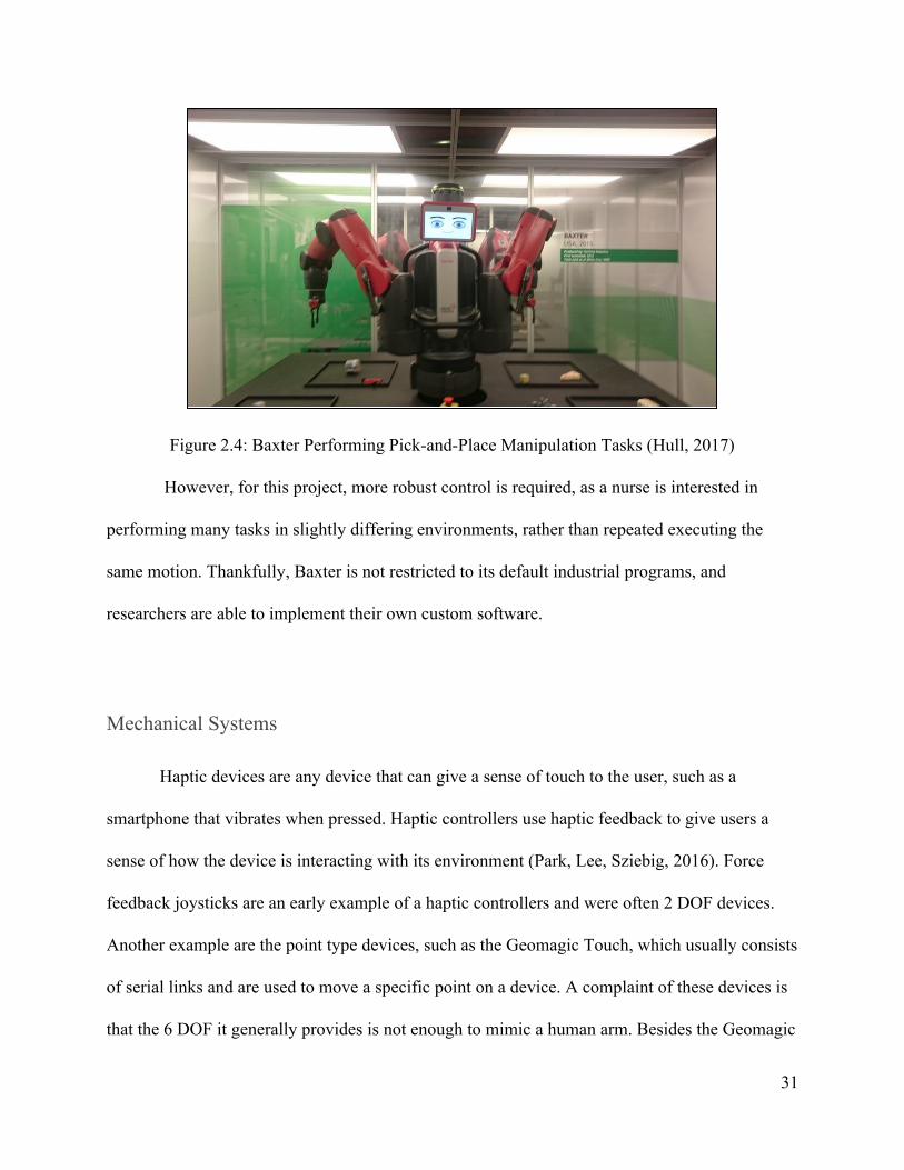
Figure 2.4: Baxter Performing Pick-and-Place Manipulation Tasks (Hull, 2017)
However, for this project, more robust control is required, as a nurse is interested in
performing many tasks in slightly differing environments, rather than repeated executing the
same motion. Thankfully, Baxter is not restricted to its default industrial programs, and
researchers are able to implement their own custom software.
Mechanical Systems
Haptic devices are any device that can give a sense of touch to the user, such as a
smartphone that vibrates when pressed. Haptic controllers use haptic feedback to give users a
sense of how the device is interacting with its environment (Park, Lee, Sziebig, 2016). Force
feedback joysticks are an early example of a haptic controllers and were often 2 DOF devices.
Another example are the point type devices, such as the Geomagic Touch, which usually consists
of serial links and are used to move a specific point on a device. A complaint of these devices is
that the 6 DOF it generally provides is not enough to mimic a human arm. Besides the Geomagic
31

Touch, other devices include arm mounted haptic devices and gloves, in conjunction with a
video motion capture system. These are haptic devices that are meant to map human movement
as closely as possible. (Qin et. al, 2015)
When building haptic devices, a form of actuation is needed to provide the force
feedback. This is usually a vibration motor. Typical vibration motors consist of motors with
unbalanced weights on the end that cause the vibration, due to conservation of angular
momentum. Another type of vibrational motors is linear resonant actuators (LRAs). LRAs can
vibrate to deliver variable force feedback along a given access, where other vibrational motors
vibrate in two axes. (Precision Microdrives, n.d)
Given that the device is intended to be used for long periods of time, ergonomics is a large
concern. Certain body positions and repetitive motions can expose workers to risks of
Musculoskeletal Disorders. (United States Department of Labor, n.d.) Working with the robopuppet
the design may involve some of these at-risk positions. Though the input device cannot entirely
eliminate these hazards, it is important to take steps to mitigate them by taking ergonomics into
consideration. In order to improve operator posture it is important to have the monitors being used to
monitor the real-world robot at eye level and directly behind the control device. (Mayo Clinic, 2016)
In addition, it is recommended that tools be padded and as light as possible. Maintaining a straight
neck and wrist when using tools is also advisable, so tools should be placed in areas where severe
bending is not required. The RoboPuppet may have to be adjustable in order to be ergonomic and
safe to operate for users of different heights and body shapes. Another ergonomic best practice is to
hold materials in place with clamps or other devices, so that users don’t have to exert themselves
32

holding things in place. This means that it will be important for safety that the robopuppet can
maintain its position without constant user input. (Lampl, 2008)
Mechatronic Systems
It was decided early in the project, that some form of torque feedback would need to be
installed on the puppet. A significant amount of research was undertaken to understand which
technologies to use, how to implement this actuation, and the best practices. The purpose of the
torque feedback has many uses:
● Link resting: Allows the links to remain “floating” while the user is not operating the
puppet. Can be toggled on with a dead man switch floor pedal. This feature is necessary
to maintain safety. If the user lets go of the input device, for any reasons, the controlled
Baxter will reciprocate and lower its arm, and potentially dropping things.
● Gravity Compensation: Applying a torque on each link, that is equal to the moments
induced by the weight of the rest of the arm links. The user will need significantly less
effort, and perceive the input device as “weightless”.
● “Soft” Force feedback: Moving the puppet links too quickly could cause the robot to go
out of control. Baxter does not move very quickly, and it is quite easier for the user to
move too quick and the controller becomes disjoint from the real robot. A torque can be
applied that is in proportion to this error. More substantial differences will be responded
to through stronger haptic feedback.
33

To apply a torque on the joints, different forms of actuators were researched. The first
type of actuator were electric motors, which can be divided into DC permanent magnet motors
and AC, field wound motors. In addition, motors can be classified as brushed or brushless -
referring to the way that the armature is located within the stator. However, controlling any of
these motors would be difficult, as they would need to be controlled in a way that is against their
intended design. Rather than rotate as a given speed, and apply a torque dependent on the
environment, it is necessary for the motors operated at a given torque, and apply a speed that is
environmentally dependent. To research what qualities would be needed, an interview was
conducted with Professor Kenneth Stafford. From the interview, several key motor variables
were discussed.
1. The motor must supply the requisite power or it cannot be used. While a great first step
for selection of motors in more typical applications, since the angular velocity is arbitrary
for this haptic devices, it is difficult to quantify the power requirements.
2. Gearboxes are used on motors to reduced the shaft speed and increase torque. However,
gears do have frictional losses. A threshold of 200:1 was given as the maximum
acceptable gear reduction. Beyond that, the user would not be restrained by back-emf, but
by friction between gears. A more ideal situation would be a 100:1 reduction. In addition,
worm gears, and other non-backdrivable gearboxes will need to be avoided outright.
Since the controller links should not be rotated quickly at all, and the motor cannot be
aided by a high reduction gearbox, the motor must be able to operate well at low speeds.
Moreover, the electrical current required to apply the necessary torque from the motor, must be
34

within the safe operating limits of the motor and power delivery subsystem. In addition, the
motors will need to operate predictably with less than their nominal operating voltage.
Magnetic breaks, also calls hysteresis brakes apply a resistive torque that is proportional
to their angular velocity. Although similarly constructed to motors, they are not designed to drive
a rotational load, but rather restrict the speed of shafts on machines, that are externally driven.
This makes the breaks very good for locking the RoboPuppet in place, but does not allow for
haptic feedback. Additionally, the torque to weight ratio was lower than the cheaper and more
easily to obtain servos. This ultimately lead to considering other options for actuation.
An alternative to using motor torque to provide feedback would be with vibration motors.
The key benefit is they do not produce an angular displacement on the joints, which would help
maintain accuracy, and do not need to be coupled between links, which would simplify the
mechanical design. However, the vibration motors cannot produce a torque to keep the arm from
moving. This would mean relying fully on the user to adjust their manipulation speed, based on
the directives of the vibration motors, rather than using the torque to push back against user’s
input. These motors would also be unable to perform any form of gravity compensation,
One key problem with motors and other such devices is that they need to be mounted
directly to the arms. For gravity compensation, this is additional weight that must be supported,
thus requiring larger, heavier motors. The Davinci surgical robot has a similar design constraint,
as it requires slender limbs to operate in tight spaces. To overcome this obstacle, the Davinci
robot uses a cable and pulley system to actuate its joints. This allows the actuators to be stored
remotely in the base unit. Three main complications exist with this implementation. A
complicated internal pulley system would need to be designed. If the input device is kept at a
35

size which would still be ergonomic to operate, the mechanical design would be unprecedented
and perhaps impossible. Second, the cables must be kept in constant tension in both directions
(to ensure full mobility of the arms), which would add significant complications to the assembly.
Lastly, the DaVinci surgical robot uses braided tungsten cables as any elongation would
significantly hinder precision. Such cables are are substantially beyond the budget of this project.
Software Systems
The main software architecture used for the project is the TRINA Software stack. It is an
integrated middleware, motion planner, simulator and controller interface software stack. In
order best integrate with other researchers at the WPI HIRO Lab, the use of this software stack is
a constraint. Figure 2.5 diagrams the TRINA software system
36

Figure 2.5: Overview of TRINA Software Stack (Hauser et at n.d.)
The software that TRINA, and this project is based on is the Robot Operating System
(ROS). Despite the name, ROS is not an operating system, but rather a code framework. At the
heart of ROS is the idea of modularity. A robot operating with ROS will typically run a number
of nodes, each handling specific functions, as well as a core that facilitates the passing of
information between the nodes. In order to communicate, ROS nodes publish messages
containing data to specific topics. Other nodes listen to these topics waiting for messages to be
received and operate on that data, either using it to affect motion of the robot or publishing the
results to a different topic. By separating the robot software into subsystems, ROS offers the
ability to easily adapt code to different systems. Rather than publishing code that is specific to a
single robot, ROS allows programmers to create code independent of firmware. It is important to
understand the underpinnings of ROS to fully understand the functionality of the TRINA Stack.
However it should be noted that all of the ROS commands are abstracted away, and allows the
system to function at a much level.
37

Mechanical Design and Analysis
Mechanically, this project focused on improving the design of the robopuppet. Initially, a
prototype of the Duke Robopuppet was constructed for testing and analysis. Over the course of
the project, two additional prototypes were developed to accomplish this goal, the passive
Robopuppet design, which improves upon the robustness of the originally design, and the active
RoboPuppet design, which incorporates motors into the design, as well as adding other
improvements based on Mark 0 testing. The two major focuses of the design were increasing
structural stability and maintaining Denavit-Hartenberg (DH) parameters that are identical to the
Baxter industrial robot. The following sections describe the processes and analysis involved in
the development of each prototype.
Duke Arm Design
The initial inspiration for the project’s design was the preliminary Baxter RoboPuppet
developed by researchers at Duke university. The design was an initial feasibility study to
confirm that the RoboPuppet procedure could be applied to Baxter. (Hauser, n.d) The joint
angles were sensed using potentiometers attached to the arm via a universal octagonal joint
mount. The W2 joint is not modeled in this design,.
To evaluate the strengths and weaknesses of this design, the team constructed a prototype
based on CAD from the Duke project. This design posed several difficulties. First, the device is
entirely passive. There is no actuation feedback to the user, and the user must support the puppet
38

arm’s entire weight. With no actuated feedback, users sometimes moved the arm to quickly for
the robot to respond, leading to a disconnect between the puppet’s position and the robot’s
position. Furthermore, letting go of the Duke RoboPuppet would cause Baxter’s arms to
similarly fall. Second, the potentiometer assembly was not as durable as needed. The
potentiometer itself is a load bearing member, and it is supported with a small 3d printed collar
(see figure 3.6, in Passive RoboPuppet design). During the tests of the Duke prototype, this
collar sheared off on most joint assemblies, and necessitated the use of glue to hold it back
together. Additionally, during tests team members expressed concerns with the device being
uncomfortable due to its small size. The Duke arm also lacks one degree of freedom, which
prevents the device from being able to completely mimic the behaviour of the Baxter robot. This
was a top priority to be fixed in future designs.
39

Figure 3.1: Solidworks Rendering of Duke Designed RoboPuppet
Figure 3.2: Complete Duke Designed RoboPuppet Assembly
Figure 3.3: Universal Joint Assembly for Duke Designed RoboPuppet
40
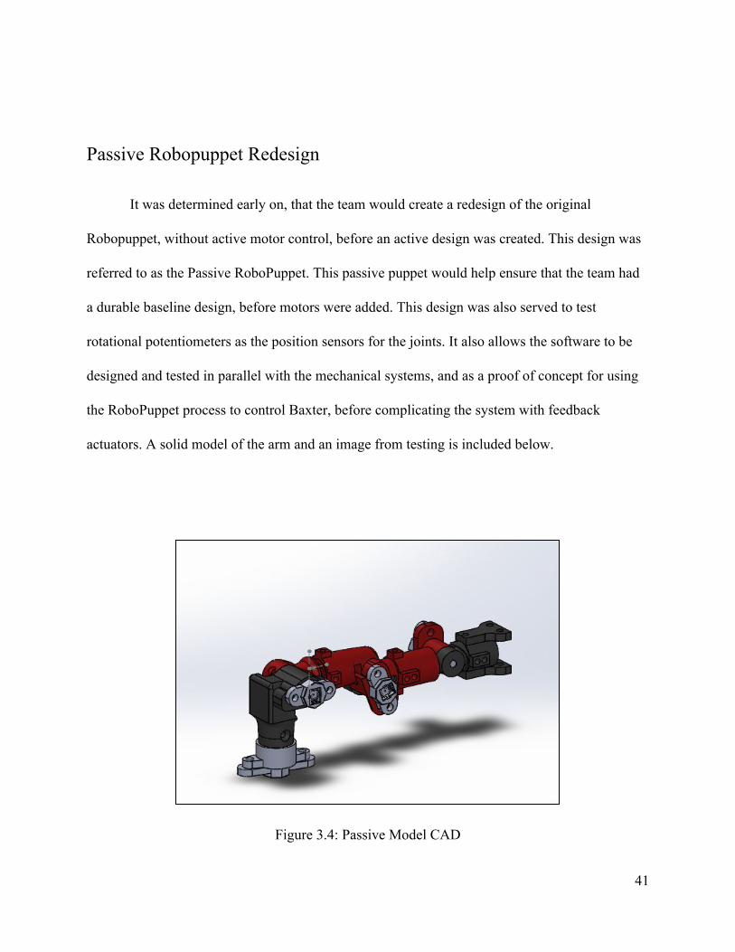
Passive Robopuppet Redesign
It was determined early on, that the team would create a redesign of the original
Robopuppet, without active motor control, before an active design was created. This design was
referred to as the Passive RoboPuppet. This passive puppet would help ensure that the team had
a durable baseline design, before motors were added. This design was also served to test
rotational potentiometers as the position sensors for the joints. It also allows the software to be
designed and tested in parallel with the mechanical systems, and as a proof of concept for using
the RoboPuppet process to control Baxter, before complicating the system with feedback
actuators. A solid model of the arm and an image from testing is included below.
Figure 3.4: Passive Model CAD
41

Figure 3.5: Assembled Passive Model
A main focus of the passive puppet was improve upon the initial design, based on the
initial research and the needs of TRINA. A major addition was the inclusion of a seventh degree
of freedom to the puppet. This allowed the user to control every joint of baxter individually and
helped make the puppet movement and behavior more accurately match that of the robot. The
other major change was the method of integrating potentiometers and connecting joints.
Originally, the potentiometers were inserted into housings which consisted of two octagons
which rotates freely with respect to each other. One end of the housing was inserted into each
end of the joint, connecting the links. The housings meant that each pot assembly was identical,
and made the design for each link similar. However, the potentiometer was press fit into the
assembly, and was located at the center of joint. This meant that the housing experienced the
majority of forces exerted on the puppet. Interior components of the housing were very thin and
resulted in the housing breaking frequently. Figure 3.6 shows the result of a sheared
42
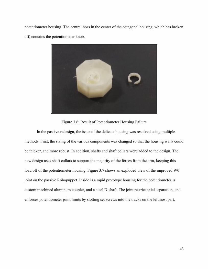
potentiometer housing. The central boss in the center of the octagonal housing, which has broken
off, contains the potentiometer knob.
Figure 3.6: Result of Potentiometer Housing Failure
In the passive redesign, the issue of the delicate housing was resolved using multiple
methods. First, the sizing of the various components was changed so that the housing walls could
be thicker, and more robust. In addition, shafts and shaft collars were added to the design. The
new design uses shaft collars to support the majority of the forces from the arm, keeping this
load off of the potentiometer housing. Figure 3.7 shows an exploded view of the improved W0
joint on the passive Robopuppet. Inside is a rapid prototype housing for the potentiometer, a
custom machined aluminum coupler, and a steel D-shaft. The joint restrict axial separation, and
enforces potentiometer joint limits by slotting set screws into the tracks on the leftmost part.
43

Figure 3.7: Exploded view of Joint W0 for passive RoboPuppet
.
Analysis of Passive Version
Our main method of analysing the passive arm was destructive testing. Specifically, the
arm’s structural integrity was tester under two conditions, under maximum static stress and under
repeated fatigue loading. We selected to mainly test the arms physically as most construction
was done with 3D printed ABS plastic. This makes the material properties difficult to predict and
would make most calculations inaccurate. By physically testing the prototype we were able to
observe and study any failures in order to locate the cause.The two conditions were selected
because these would be the most likely cause of failure in the arm.
This testing analyzed the structural stability of the passive design, as well as the strength
of the 3D printed material used. During testing, links that had failed under low loading were
printed in different orientations. This change affected the direction that the plastic layers ran
along the part. It was observed that parts were stronger when force was applied in parallel to the
plastic layers, rather than perpendicularly.
44

A secondary analysis method was to calculate the torque acting on each joint of the arm.
This type of analysis allowed us to get a sense of the loads on each of the different joints. This is
important because it allowed us to see how much more force was being experienced by the
bottom most joint than any of the others. We made these calculations using measurements taken
from SolidWorks and assuming that the arm was solid ABS. An excel spreadsheet was used to
calculate the torque values for various joints on the arm (See Appendix IV). This assumption
was incorrect, as the printed PLA is significantly less dense. However, this decision resulted in
considering higher loads, which led us to create a more robust design. Ultimately this analysis
lead to the addition of springs in the active arm design. This analysis was also used to determine
the torque output needed from the servos in the active design. All servos were selected to be able
to support the highest load experienced by the arm without stalling.
Active RoboPuppet Model
The fully actuated arm is designed to both incorporate motors into the robopuppet
controller, as well as continue to resolve issues observed during testing of the passive arm
designs. There were five key modes of improvement that the active RoboPuppet presents.
1. Improvement on manufacturing ability. Many of the links were designed with flat
spots or split to create flat spots and facilitate easier FDM rapid prototyping
2. Reduce friction. This was accomplished by the adding of bearings to all joints.
3. Improve on sensing, through the upgrade from potentiometers to Hall effect
encoders
4. Added space availability to improve cable management and ergonomics.
45

5. The implementation of motors for haptic feedback.
Actuator Selection
The key improvement with this design is the introduction of actuators on the joints. This
actuation serves two purposes: gravity compensation for the weight of the links, and haptic
feedback for the user. Several methods were considered to achieve this. Descriptions of each
option are provided below, as well as the decision matrix used to rank the options. In addition to
rank, price and availability were considered during the design process.
DC Motors
These are basic DC brushed motors.These are good for operating at high speeds, but
require frequent maintenance and often produce less torque than the brushless counterpart. They
can be compacted and can have direct velocity control.
DCBL Motors
These are standard brushless motors. They produce more torque than brushed motors and
are frequently more expensive, however they can be more power dense and size efficient.
Servo Motors
Servos are motors that feature an integrated gearbox and controller for simplified control.
The team specifically considered 360 degree rotation, metal gear, micro servos, as they would fit
the application best in this very general classification of actuator. These servos are able to rotate
46

continuously, similar to a motor, rather than having a limited angle range. The metal gear
versions are durable and can produce large amounts of torque for their size.
Marionette suspension system
This option would use cables to suspend the arm controller in the air. Brakes would hold
these cables in place when the user was not manipulating the arms. For this design, fixed pulleys
would restrict the movement of the arm. An additional concern was that cables would become
tangled. A benefit was that this solution was non-electrical and needed no wiring or power
supply. However there would be difficulties in installation, and ensuring the strings to not
collide.
Hysteresis Brakes
These brakes use magnetic fields to stop the shaft inside of the brakes. When active, the
shaft stops in place, preventing the arm from being able to rotate and locking the shaft in place.
These brakes can resist the needed amount of torque and are roughly the diameter of the Duke
Robopuppet prototype. However, they cost $280 per unit, which is antithetical to the
affordability objective for the project as a whole.
Magnetic Clutch
These clutches stop shaft rotation using friction between two materials to resist the shaft
motion. Magnets are used to pull these materials together and create the friction. The option
resists enough torque to hold the robot in place, but less than the hysteresis option. These brakes
47
are similarly sized to the hysteresis brakes, however it is unclear from the vendors whether they
can provide a partial break, or if it is a full-stop-or-nothing. This solution cost roughly $60 per
unit.
Mechanical Clutches
This type of clutch would use friction to stop shaft rotation, similar to the magnetic
clutch. However the clutch would be cable driven instead of magnet driven. This method could
homemade rather than ordered. However this would require a significant amount of novel
design. Looking into similar pre-existing solutions such as sprag clutches, it may also be difficult
to produce a design that works in both directions.
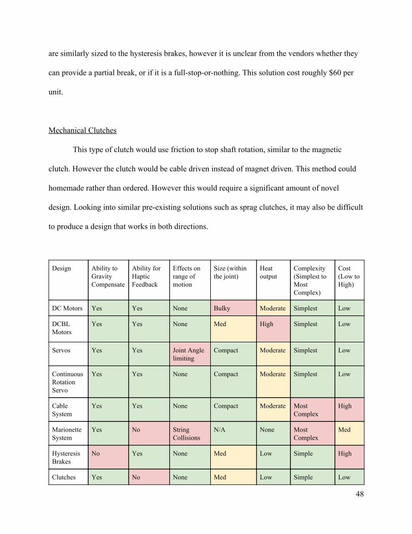
Design Ability to Gravity Compensate
Ability for Haptic Feedback
Effects on range of motion
Size (within the joint)
Heat output
Complexity (Simplest to Most Complex)
Cost (Low to High)
DC Motors Yes Yes None Bulky Moderate Simplest Low
DCBL Motors
Yes Yes None Med High Simplest Low
Servos Yes Yes Joint Angle limiting
Compact Moderate Simplest Low
Continuous Rotation Servo
Yes Yes None Compact Moderate Simplest Low
Cable System
Yes Yes None Compact Moderate Most Complex
High
Marionette System
Yes No String Collisions
N/A None Most Complex
Med
Hysteresis Brakes
No Yes None Med Low Simple High
Clutches Yes No None Med Low Simple Low
48

The above matrix discusses how each solution matches our essential criteria. We were
looking for an option that could lock the robot arm in place without restricting the motion
ranged. Preferably, these could also be used to implement haptic feedback. For the size, we
considered whether the option could fit in the joint as was originally designed(compact), needed
slightly more space(med) or could not fit in the joint(bulky). Heat output, and difficulty of
implementation were also considered. Ultimately the three best options were servos, hysteresis
brakes and magnetic brakes. All three of these options produced the needed amount of torque.
However, the servos were slightly smaller than the other options and significantly less expensive.
In addition, the magnetic brakes had a large lead time. Specifically, we went with the TowerPro
Continuous Rotation micro servo based on recommendations and reviews.
Preliminary Hand Design
The original design for gripper control consisted of two plastic “finger” links connected
to a plastic base. The fingers were connected by a set of gears to ensure that the fingers could
only move in proportion to each other and would always meet in the center. These fingers were
meant to resemble the grippers used on Baxter, and the pinching motion represented the closing
of the gripper hand. The position of the fingers was measured by a shaft mounted potentiometer.
The plastic base was design to attach to the end link of the RoboPuppet. The end attachment is
identical for the passive and active models. The assembled model can be seen in figure 3.8.
This design measured how open the fingers were, allowing the grippers to open varying
amounts. However, the fingers made the device bulky, requiring two hand to operate. This meant
49
that only one gripper would be able to be used at a time. This led to the consideration of
alternative designs.
Figure 3.8: Pincher Gripper Control
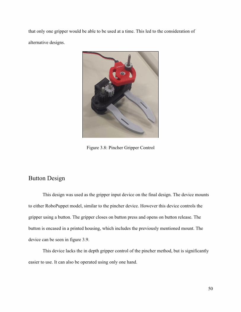
Button Design
This design was used as the gripper input device on the final design. The device mounts
to either RoboPuppet model, similar to the pincher device. However this device controls the
gripper using a button. The gripper closes on button press and opens on button release. The
button is encased in a printed housing, which includes the previously mentioned mount. The
device can be seen in figure 3.9.
This device lacks the in depth gripper control of the pincher method, but is significantly
easier to use. It can also be operated using only one hand.
50
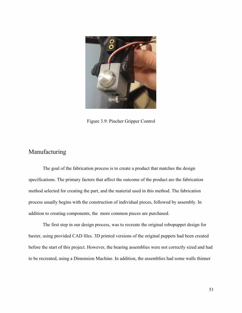
Figure 3.9: Pincher Gripper Control
Manufacturing
The goal of the fabrication process is to create a product that matches the design
specifications. The primary factors that affect the outcome of the product are the fabrication
method selected for creating the part, and the material used in this method. The fabrication
process usually begins with the construction of individual pieces, followed by assembly. In
addition to creating components, the more common pieces are purchased.
The first step in our design process, was to recreate the original robopuppet design for
baxter, using provided CAD files. 3D printed versions of the original puppets had been created
before the start of this project. However, the bearing assemblies were not correctly sized and had
to be recreated, using a Dimension Machine. In addition, the assemblies had some walls thinner
51

than could be accurately printed in some areas. To fix this, parts were printed with thicker walls
and filed down the edges.
Once the pieces were ready, the robopuppet was assembled. In order to be sure only the
original design was tested, the only modifications to the design were additions necessary for safe
testing. Specifically this was a method to hold the puppet steady when trying to set up and turn
off the device. These parts were printed with ABS plastic, because it was a standard material
used with the machine that had previously been used to make the Robopuppet parts. Aside from
the printed parts, bearings and potentiometers that had previously been purchased for this project
were used.
The next design was of our passive robopuppet design, improving on the Duke Model.
The majority of the arm was printed using a Lulzbot printer. The major modification to this
design was the change in location of the potentiometer. Rather than being inserted as part of the
joint assembly itself, the potentiometers were located a distance away from the joint and
connected to the joint assembly with shafts. Another change was that this design included both a
left and right hand. Links for the two arms were mirrored in order for the distinction between the
two arms to be clear.
In addition, couplers were needed to connect potentiometers to the shafts, which were
added to the design. These couplers were machined from aluminum rods using lathes and drills.
In addition, heat set inserts were added to some 3D printed pieces in order to allow set screws to
be inserted into the part. These screws were used to hold the shafts into place. In addition, these
screws were inserted into slots, as part of the assembly of wrist joints. The slots kept the two
links from separating from each other while allowing them to rotate freely. However the slots
52

and set screws created a large amount of friction, which had to be reduced using silicone grease.
The set screws used in the assembly also came undone somewhat easily. To compensate for this,
extra clearance holes were added to each links to provide easier access for removing shaft collars
and adjusting the set screws within. Loctite was applied to the screws to help prevent future
loosening as well.
For the first arm of this design, one link cracked along the direction of the ABS threads.
To fix this, a replacement was created, printed in a different orientation. This changed the
directions of the ABS threads throughout the part, making it stronger.
For the Passive design, wrist joints were created by inserting a slotted cylindrical link
into a hollow link. Set screws were then inserted into the slots to hold the joint together. This
kept the new design similar to the original Duke design. However, printing these parts required
support material that was difficult to completely remove from the finished part. This added extra
time to the manufacturing process. Rough edges from where support material was removed also
made it difficult for some parts to fit together. This lead to prioritizing an ease of 3D printing
when creating our design of the active puppet.
Once the initial puppet was completed, work began on fabricating the initial designs of
the gripper controller, as no initial design existed for this component. To simplify assembly, the
gripper controller was designed to use vex shafts and standoffs. The design consists of two 3D
printed halves of a hand. Two curved, printed fingers were added at the left and right edges of
this hand. They were connected by 3D printed gears, so that the two fingers moved together. The
gear ratio was 1:1. The fingers included hook and loop straps that could be used to attach the
53

fingers to the user’s real fingers. This would allow the user to more easily manipulate the
controller.
The final prototype constructed for this project was the Active design. This version
included motors, to help keep its position when not in use. This version also replaced the
potentiometers with hall effect encoders, due to the sensors providing a better joint angle
reading.
This arm design print links in two halves. This allowed for pieces to be printed with
fewer supports, and also allowed for motors and shafts to be more easily inserted inside during
assembly. This version used the same printer, shafts and set screws as the passive design. It used
new custom couplers to attach to the hall effect magnets, made from the same stock as the
passive design. Using the same base components allowed for easier transfer of design
components from the passive to active design. Like all the previous arms, the links are all very
similar to each other. However, the actual link design for the active is differs greatly from the
Duke design in order to better accommodate the added volume from the motors.
For assembly the bottom most joint, referred to as S0, was assembled before the other
pieces were manufactured. This allowed for identification sizing and tolerancing issues and
adjust the future parts to accommodate the errors. It also allowed for testing of the motors,
sensors and structural integrity of the concept before committing too many resources to the
design. Once this first joint was created, the other links were manufactured and added. The
majority of the Active model was 3D printed, though shaft collars were machined from steel for
added stability.
54

Electrical Engineering Design and Analysis
This chapter contains the design and analysis of the electrical subsystems in the Passive
and Active RoboPuppets. The section will cover the sensing capabilities, actuation, onboard
processing, power delivery, and wiring sub-systems.
Arm Angle Sensing
It is imperative to sense the angle of each joint in the RoboPuppet’s arm, as these are the
control inputs to Baxter. For the passive RoboPuppet, potentiometers were used for their
compact packaging and ease of use. For the active robopuppet, hall effect absolute encoders were
chosen for their superior precision through the use of 14-bit ADCs, mechanical durability due to
lack of a mechanical linkage, and ease of implementation thanks to the integrated digital signal
processors.
Passive RoboPuppet Arm Angle Sensing
The Passive RoboPuppet draws significant inspiration from the original Duke designed
RoboPuppet. Hence, the same potentiometer joint angle measurement system was employed. The
potentiometer used is a 270 degree analog potentiometer. Figure 4.1 is a photo of the
potentiometer before installation into the passive RoboPuppet.
55

Figure 4.1: Potentiometer
It is necessary to calibrate the potentiometers in order to relate the signal they output to
the angle that they measure. Two procedures were done. First, a single potentiometer was
calibrated in isolation in order to get a sense of the data trend. Second, the potentiometers were
calibrated on the arms themselves to relate the arm-relative position to the signal that is
outputted. Figure 4.2 demonstrates a fixture used to measure the angle of the potentiometer in
isolation for calibration. The potentiometer was set to various known angles, and then data was
captured. The potentiometer was wired such that a 5 volt supply was applied, and the return
signal was fed into an Arduino Mega microcontroller’s 10-bit analog-to-digital converter. The
microcontroller transferred the sensor data over usb to a host computer. Using PuTTY, the data
was collected into a Google Documents spreadsheet, to perform numerical analysis.
56

Figure 4.2: Calibration Fixture
The isolated potentiometer demonstrated that the sensors are nearly linear with an R2
value of 0.988, which indicates a clear correlation to the linear curve fit. Figure 4.3 shows the
results from testing with 1676 samples. Note that the angles on the graph are set so that the
rightmost hardstop is zero degrees.
57

Figure 4.3: Isolated Potentiometer Calibration Data
The sensor is most linearly between 30 and 220 degrees but there is a significant
divergence near the ends. There, the angle changes, but the signal does not. The cause is likely
do to a low quality application of the resistive material, where at the extremities, only exists a
direct conductor to either the high or low power rails. This dead zone is problematic as it is
impossible to perform the inverse process, finding the angle by reading a sensor data, as a single
value could be one of many angles. This problem was largely resolved by mechanically adjusting
the potentiometers so that they need not operate in these domains.
Once the single pot was tested in isolation to confirm the linear model and to determine
the extent of the dead zones, the joints on the passive robopuppet themselves were calibrated. A
nearly identical procedure was done to calibrate the potentiometers. Instead of the printed guide,
58

a protractor was used to measure the angles off of the zero positions. The known angles were
held as data and captured to create graphs, from which linear trends were formed. The zero
positions of each joint are defined from the Rethink Robotics hardware specifications for Baxter,
as that convention is used elsewhere in the software stack. Figures 4.4 and 4.5 indicate where the
zero degree points are for each joint, as well as their range of motion. The dashed grey lines
represent the zero angle when the direction of the links (solid black indicator lines) are
coincident. The solid grey lines are the joint limits.
Figure 4.4: Zero Positions and Joint Limits for “Bend Joints” (Rethink Robotics, 2015)
59
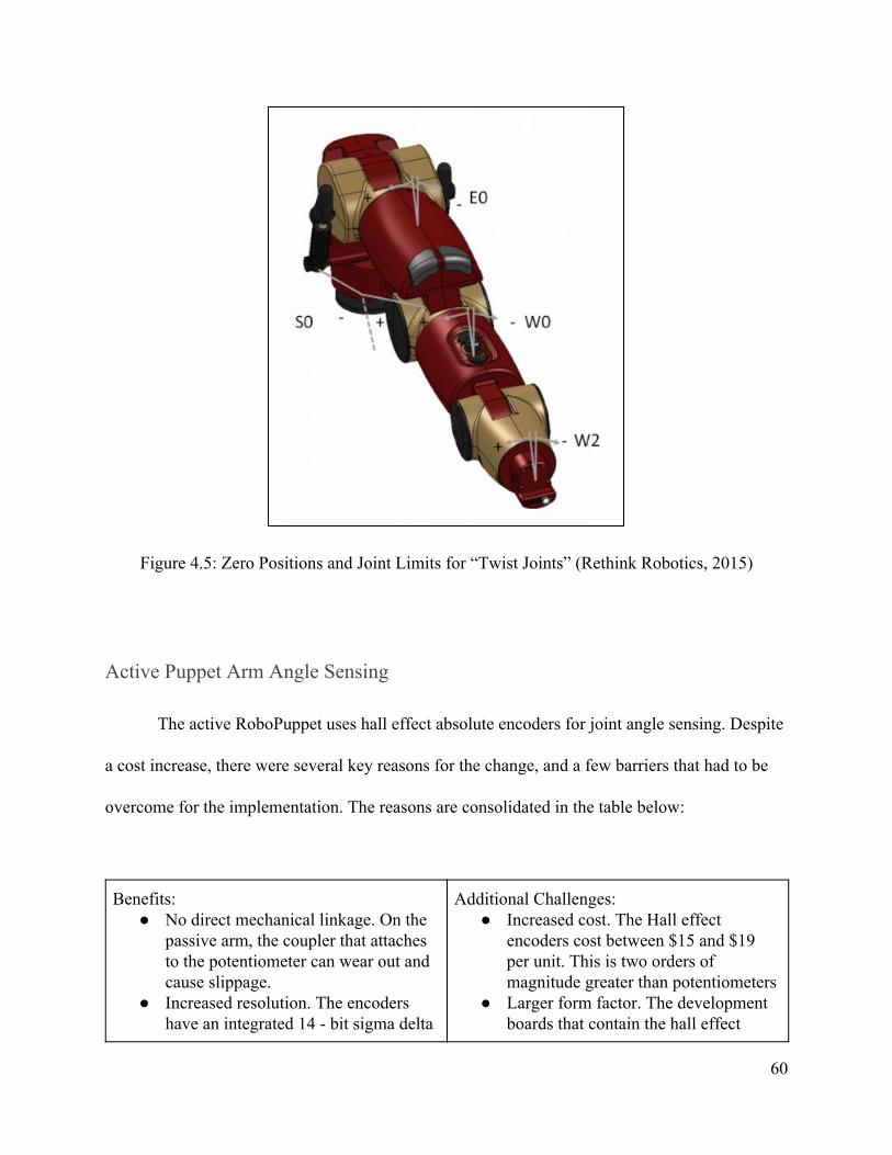
Figure 4.5: Zero Positions and Joint Limits for “Twist Joints” (Rethink Robotics, 2015)
Active Puppet Arm Angle Sensing
The active RoboPuppet uses hall effect absolute encoders for joint angle sensing. Despite
a cost increase, there were several key reasons for the change, and a few barriers that had to be
overcome for the implementation. The reasons are consolidated in the table below:
Benefits: ● No direct mechanical linkage. On the
passive arm, the coupler that attaches to the potentiometer can wear out and cause slippage.
● Increased resolution. The encoders have an integrated 14 - bit sigma delta
Additional Challenges: ● Increased cost. The Hall effect
encoders cost between $15 and $19 per unit. This is two orders of magnitude greater than potentiometers
● Larger form factor. The development boards that contain the hall effect
60
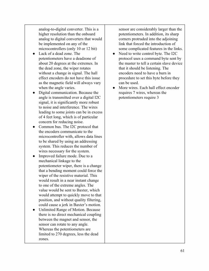
analog-to-digital converter. This is a higher resolution than the onboard analog to digital converters that would be implemented on any of the microcontrollers (only 10 or 12 bit)
● Lack of a dead zone. The potentiometers have a deadzone of about 20 degrees at the extremes. In the dead zone, the wiper rotates without a change in signal. The hall effect encoders do not have this issue as the magnetic field will always vary when the angle varies.
● Digital communication. Because the angle is transmitted over a digital I2C signal, it is significantly more robust to noise and interference. The wires leading to some joints can be in excess of 4 feet long, which is of particular concern for reducing noise.
● Common bus. The I2C protocol that the encoders communicate to the microcontroller with, allows data lines to be shared by using an addressing system. This reduces the number of wires necessary for the system.
● Improved failure mode. Due to a mechanical linkage to the potentiometer wiper, there is a change that a bending moment could force the wiper of the resistive material. This would result in a near instant change to one of the extreme angles. The value would be sent to Baxter, which would attempt to quickly move to that position, and without quality filtering, could cause a jerk in Baxter’s motion.
● Unlimited Range of Motion. Because there is no direct mechanical coupling between the magnet and sensor, the sensor can rotate to any angle. Whereas the potentiometers are limited to 270 degrees, less the dead zones.
sensor are considerably larger than the potentiometers. In addition, its sharp corners protruded into the adjoining link that forced the introduction of some complicated features in the links.
● Need to write control byte. The I2C protocol uses a command byte sent by the master to tell a certain slave device that it should be listening. The encoders need to have a burn in procedure to set this byte before they can be used.
● More wires. Each hall effect encoder requires 7 wires, whereas the potentiometers require 3
61

In order to ensure that the hall effect encoders properly work, a fixture was made to
contain a hall effect sensor, and a magnet in the correct orientation. Fixture is effectively the first
joint of the Active Robopuppet. Electrically, an Arduino Uno was used to read data off of and
communicate to the sensor. Figure 4.6 is an overview of the testing setup.
Figure 4.6: Testing setup for hall effect encoders
The testing procedure involved a couple of steps. Note that it is necessary to electrically isolate
the microcontroller from the rest of the hall effect encoder circuit when the microcontroller being
programmed. This is to prevent inadvertent communication of the I2C bus to the hall effect
encoder. Some of programs are designed to permanently burn the fuses on the hall effect
encoders and is critical to only run when intended. The procedure is as follows:
1. Run the program to set the control byte on the encoder board. A specific register address
is used to initiate the burn in procedure
2. Run the program to verify the control byte value
62

3. Run the program to read off values from the encoder to successful operation
Once the encoders have been burned in, they are installed in the active RoboPuppet as seen in
figures 4.7 and 4.8
Figure 4.7: Mounting of Hall Effect Encoder on S1 Joint
Figure 4.8: Mounting of Hall Effect Encoder on S0 Joint
63
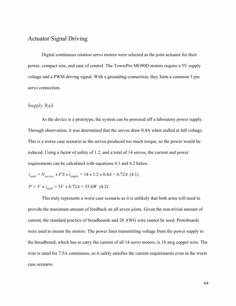
Actuator Signal Driving
Digital continuous rotation servo motors were selected as the joint actuator for their
power, compact size, and ease of control. The TowerPro MG90D motors require a 5V supply
voltage and a PWM driving signal. With a grounding connection, they form a common 3 pin
servo connection.
Supply Rail
As the device is a prototype, the system can be powered off a laboratory power supply.
Through observation, it was determined that the servos draw 0.4A when stalled at full voltage.
This is a worse case scenario as the servos produced too much torque, so the power would be
reduced. Using a factor of safety of 1.2, and a total of 14 servos, the current and power
requirements can be calculated with equations 4.1 and 4.2 below.
(4.1)S 4 .2 .4A .72Aitotal = N servos * F * isingle = 1 * 1 * 0 = 6
(4.2)V .72A 3.6WP = V * itotal = 5 * 6 = 3
This truly represents a worst case scenario as it is unlikely that both arms will need to
provide the maximum amount of feedback on all seven joints. Given the non-trivial amount of
current, the standard practice of breadboards and 28 AWG wire cannot be used. Protoboards
were used to mount the motors. The power lines transmitting voltage from the power supply to
the breadboard, which has to carry the current of all 14 servo motors, is 18 awg copper wire. The
wire is rated for 7.5A continuous, so it safely satisfies the current requirements even in the worst
case scenario.
64

Note that this current is between the two standard current ratings for 18 AWG wire of
chassis wiring and power transmission. As only a pair of wires will be used and they will be
dangling in relatively open air, it is acceptable to assume the wire can perform closer to the
higher end of the wire’s current carrying capabilities of 16 A.
Microcontroller Signal
The Towerpro MG90d is a servo motor. The servo is controlled using a PWM signal.
Two different libraries exist within the Arduino library for generating PWM signals. The Servo.h
library is used for controlling position servos. When that library is used, the write method causes
the servo to go to a particular angle, and apply a holding torque. Internally, the servo contains a
360 degree potentiometer to measure absolute position. Care was taken by the designers to
ensure that a short circuit would not occur at the overflow point, allowing the servo to rotate
continuously.
The way to generate a PWM waveform with the Arduino library is the analogWrite
method. This method generates a variable duty cycle pwm waveform. There is 8 bits of
resolution on the duty cycle. Interestingly, when this approach is taken, the servo behaves as a
velocity controlled servo (acting essentially as a standard DC motor). Since it is desirable to
apply a specific torque rather than reach a specific position, the velocity controlled servo
capability is more desirable for this application.
65

Wiring and Wire Management
Wire management is an important consideration for the electrical subsystem. Besides
aesthetics, it is relevant to increase clarity of what the wires connect to (and therefore make
debugging easier), improve airflow, and prevent wires along the arms from getting caught and
restricting motion. On virtually all commercial robot arms, the wiring is kept internal. However,
the small arms of the robopuppet lack the cross sectional area necessary to have voids to run
wires along. Therefore it was necessary to run the wires externally along the arms, and utilize
cable ties to keep them neat and along the links. Care was taken to ensure that the wires were not
too tight, as that could restrict the range of motion in the arms. However, it is prudent to not have
the wires arranged too loosely, as the dangling wires can catch on other components. Figure X
shows the compromise taken to ensure good maintenance of the servo motor wires on the active
robopuppet.
66

Figure 4.9: Motor wire management on active
The data line, clock line, 5V rail, 3V3 rail, and ground lines are all common. However
the two pins for configuring the 2 least significant bits of the address need to be either grounded
or pulled high. One idea to reduce the number of wires is to daisy-chain the hall effect encoder
wires. The end goal would be to have a single 7-conductor ribbon cable for each arm. However,
given the physical interface with the encoder boards, it is not feasible to have 2 sets of wires
going to each port. So individual 7 conductor ribbon cables were wired to each encoder.
Three methods were investigated for physically containing the circuits: breadboads,
solder-boards (protoboards) and printed circuit boards (PCB’s). Breadboards were mainly used
for their fast development time, given that no tools are needed. However, the wires are not as
robustly attached to the board as a soldered solution, and on occasion, wires became
67
disconnected. Additionally, a previous iteration of the passive arm had a breadboard mounted on
the side. This caused the backing to delaminate and remove some of the conducting pins along
with it. This was a result of long term shearing and not a sudden shock damage.
In between the near instant development speed of breadboards and the professional
appeal of PCB’s, are solder boards. They are grid matrices of tinned holes that allow wires and
components to be firmly soldered in, and traces connecting. The practice of laying down traces
to connect pins turned out to be problematic. For the hall effect encoders, it was necessary to lay
down 5 parallel traces accross 7 connectors with additional traces for the control byte jumpers.
The dense cluster of soldering turned out to be infeasible and not worth any gains in robustness
over breadboards.
PCB’s were considered the most ideal option as they are the archetype used in all
consumer electronics. However there would be a significant time period to develop the circuit
designs and verify that they will work, on top of the lead lead time and cost to produce. Given
the objective simplicity of the custom circuits used, the PCB option was not seriously pursued.
However, it is a consideration for later iterations looking to improve the professionalism and
durability of the RoboPuppet.
Microcontroller Selection
A system-on-a-chip microcontroller is used on all of the robopuppet to handle the low
level sensor reading, transmission to the TRINA stack, and haptic control algorithms (in the case
of the active RoboPuppet). Several key specifications were considered when selected
microcontrollers for the active and passive RoboPuppets. Though none of the tasks were overly
68
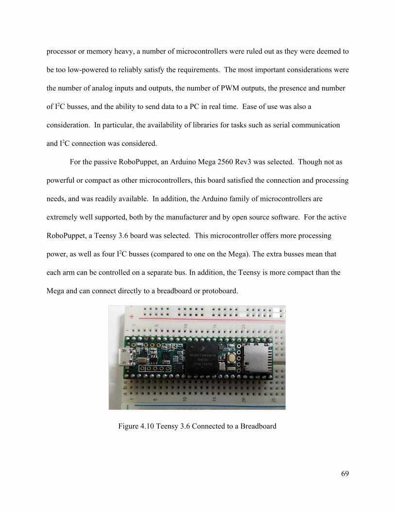
processor or memory heavy, a number of microcontrollers were ruled out as they were deemed to
be too low-powered to reliably satisfy the requirements. The most important considerations were
the number of analog inputs and outputs, the number of PWM outputs, the presence and number
of I2C busses, and the ability to send data to a PC in real time. Ease of use was also a
consideration. In particular, the availability of libraries for tasks such as serial communication
and I2C connection was considered.
For the passive RoboPuppet, an Arduino Mega 2560 Rev3 was selected. Though not as
powerful or compact as other microcontrollers, this board satisfied the connection and processing
needs, and was readily available. In addition, the Arduino family of microcontrollers are
extremely well supported, both by the manufacturer and by open source software. For the active
RoboPuppet, a Teensy 3.6 board was selected. This microcontroller offers more processing
power, as well as four I2C busses (compared to one on the Mega). The extra busses mean that
each arm can be controlled on a separate bus. In addition, the Teensy is more compact than the
Mega and can connect directly to a breadboard or protoboard.
Figure 4.10 Teensy 3.6 Connected to a Breadboard
69

Dead Man Switch
A high level design requirement for both the passive and active RoboPuppets is to have a
means to disengage control of TRINA if the operator needs to take a rest or if a sudden event
causes them to release the puppet. A dead man switch was selected due to its prevalence in other
applications, including industrial machine tools, and train conductor consoles. A dead-man
switch is a floor mounted switch that must be depressed in order for the machine to operate. If
the user lets go of the peddle, either intentionally or in an emergency, the TRINA system shall
cease motion and not respond to input from the RoboPuppet. In the active RoboPuppet, an
addition feature was designed to lock the puppet arms to the same pose as Baxter, using the
integrated motors. This is to ensure that when operation resumes, the puppet pose will accurately
reflect what will be performed by Baxter.
70

Software and Control Design and Analysis
High Level Overview
The software for the RoboPuppet controller is split into two major sections: the Python
code running on the PC and the C++ code running on the microcontroller. The microcontroller
calculates the current joint angles and transmits them to the PC over a USB UART connection.
The Python code is tasked with receiving this data and passing it into the TRINA stack, which in
turn controls the physical or simulated TRINA robot. The process is illustrated in Figure 5.1
below:
Figure 5.1: TRINA Stack Process
For the active RoboPuppet, the software will operate in a similar manner, but will include
the ability to send feedback from the robot to the microcontroller. This feedback, in the form of
the current joint angles of the robot, is used to determine the torque desired for haptic feedback.
Figure 5.2 below illustrates that data that will be passed between each device in the system
Figure 5.2: Active RoboPuppet Software Strategy
71
Passive RoboPuppet Software Architecture
The software for the passive RoboPuppet is fairly straightforward. The Microcontroller
code, at a high level, does three things: reading the values of the potentiometers, calculating the
actual joint angles from those values, and sending those angles to the PC. Because the angle
sensors for passive are analog potentiometers, the microcontroller software simply uses the
analogRead function from the Arduino library to read the value. The angles are calculated from
these values using calibration data that is hardcoded into a header file. The angles are organized
into a struct containing 14 floats for the angles and 2 longs (on an Arduino, the long data type is
the same size as the int data type is on the PC) for the gripper states. Once the values are
properly stored, the entire struct is transmitted to the PC using the standard Arduino serial
library.
The microcontroller code is also responsible for engaging and disengaging the robot. The
user indicates that they want the RoboPuppet to actively control the robot by stepping on a foot
pedal. When this pedal is disengaged, the microcontroller will continue to send the most recent
“safe” angles until the pedal is reengaged. On startup, the angles default to 0, which correlates to
TRINA’s limbs parallel to the floor.
In order to smooth the motion of the robot and remove any oscillations caused by a user’s
shaking hands, a number of filtering techniques were discussed during the planning stages.
These methods ranged from a simple moving average filter to more complex Kalman filtering.
After initial testing, however, it was determined that any oscillations caused by the user were
72

made negligible by the slow speed of the robot. Neither the physical nor simulated robot were
responsive enough to be affected by high frequency oscillations in the target joint angles.
The Python script running on the PC receives the struct containing the joint angle data
before using the unpack function from the struct library to break it into a tuple containing usable
data. At this point, the script passes the desired angles to TRINA. Rather than directly
controlling the robot, the Python script is written as a plugin for the TRINA stack. This means
that the script simply has to package the joint angles into a task message (a data type similar to a
struct and defined by the TRINA stack) and pass this into the stack. The rest of the control is
handled by the lower level software. The script is capable of identifying and connecting to an
Arduino connected to any USB port on the PC, and has a limited ability to recover if the Arduino
is connected after the script has been launched.
Active RoboPuppet Software Architecture
The software for the active RoboPuppet will take the software for the passive device and
expand it to include feedback from the robot. The differences in the hardware design between
passive and active will also necessitate a handful of changes in the microcontroller code. In
particular, the analog potentiometers have been replaced with digital Hall Effect encoders. This
requires the microcontroller to connect to them using the I2C protocol, instantiated using the
default libraries from Arduino. The microcontroller will also be responsible for implementing
gravity compensation. This can be done without additional information from the PC, as it only
requires the current joint positions of the RoboPuppet and information about their lengths and
weight. When the foot pedal (see Passive Software Architecture) is disengaged, the active
73

RoboPuppet will not only transmit the previous joint angles, but will physically lock the
RoboPuppet in place. This will be implement with a Proportional Integral Derivative (PID)
controller holding the RoboPuppet in its most recent position until the pedal is reengaged. The
Python script for the active RoboPuppet also builds upon the script for passive, adding the ability
to read the current joint positions of TRINA and pass these to the microcontrollers.
Gravity Compensation Controller Policy
Two gravity compensation controller policies were idealized. The first is a simple PID
approach, and the second is a more robust, but difficult to implement, dynamic model based
design. The first method only seeks to keep the arm locked when the deadman switch is released.
The approach would be to capture the puppet joint state when the pedal is released, and run a
positional PID controller to maintain that position, using the RoboPuppet’s hall effect encoders
as feedback sensors. The positions will also cease being transmitted to TRINA. This technique
has an advantage over the passive RoboPuppet deadman switch implementation that will keep
the puppet in the same locked pose as Baxter, thus improving safety upon startup. A further step,
in the event of a serious discontinuity between the puppet and Baxter, would be to use the
RoboPuppet as a robot arm, as it effectively is one, to move to Baxter’s pose and resume
parlerity.
For the dynamic model based approach, the equations are derived by using the
Euler-Lagrange formulation equations in non-equilibrium form, where the Puppet arms’ transient
response is equal to the applied motor torques τ, and the manifestation of external forces on the
end effector Fe. J is the manipulator Jacobian, M is the inertia tensor, C is the coriolis vector, G is
74
the gravitational vector, and q is the joint state. Equation 5.1 shows the original formulation. All
vector quantities are indicated with bars.
F q (q, ) (q)τ + JT = M ′′ + C q′ + G (5.1)
The first step to implementing the gravity compensation is to determine the exact lengths,
weights, and inertias of each joint. It is important that these values include everything that will
be attached to the robot during operation, such as the gripper modules, wires, and cable ties used
for wire management. Most CAD softwares are capable of providing a reasonably precise
numerical calculation of the mass, center of mass, and moment of inertia, provided that the
model is extremely detailed and accurate.
Assuming that the speed that the arms will be moving is quite slow, the inertial and
colaris forces can be neglected. Further discussion on the model based gravity compensation, is
continued after the introduction of the haptic feedback scheme.
Haptic Control Scheme
The Baxter robot is not capable of making very fast rapid motions such as the industrial
articulated robot arms of ABB, Fanuc or Puma. The slow speed was an engineering design
tradeoff to ensure that Baxter can operate safely around humans. However, given the relatively
small size of the RoboPuppets, it is quite easy for the user to jossel the arms at higher speeds
than the robot can output. Using the integrated actuators on the Active RoboPuppet, a haptic
control policy is realized. This scheme is to run in addition to the gravity compensation scheme.
The idea considered is classified as “soft” haptic feedback. The torque applied is in proportion of
75

the joint error. Equation 5.2 shows the torque calculation policy. KH is a gain, and q refers to the
measured joint angles of Baxter and the Puppet.
q )τ = KH * ( Baxter − qP uppet (5.2)
If the user move the arm very fast, a significant error will emerge and the controller will
ideally compensate with a larger feedback torque. The goal is to train the user to the speed limits
of Baxter, by repeated application of these resistive torques.
The “soft” haptic feedback scheme differentiates itself from a “rigid contact” haptic
feedback scheme, where the torque is directly sensed from the joints of Baxter and transferred to
the user. This rigid scheme has the advantage of better indicated when collisions occur. However
this approach adds significant complication to the communication protocol. Ideally a 10 kilohertz
outer control loop would need to be established in order to ensure that the transmission of torque
feels “smooth” to the user (Fischer and Harrington, Personal Interview).
76

Conclusions
Testing
After manufacturing, each model was tested using a KLAMPT simulation of Baxter. The
passive design was manufactured and tested first, so that results could bring insight to design of
the active model. Additionally, individual components were tested before the full manufacturing
of a model.
Before testing of the full passive model, the potentiometers were tested inside of each of
the individual joints. This allowed for observation of the behaviour of the sensor output and
calibrate each sensor individually.
When testing the passive design, there were four major concerns. These were, the
durability of the puppet, user comfort when using the puppet, ease of using the puppet and
accuracy between the puppet and simulation position. Durability was tested through observations
of the mechanism during other tests. Any mechanical failures or weaknesses were documented.
Comfort and ease of use results were obtained through objective reports from each team member
while testing the device. The accuracy of the controller position was tested by roughly measuring
the position of the mechanism and comparing this to the position of the simulated robot, as well
as to the potentiometer outputs.
When testing the active design, the first shoulder joint was fabricated and assessed first.
This allowed design errors and manufacturing difficulties to be identified without committing the
resources of a full arm to the test. While testing this joint, the main focuses were the behaviour of
77

the servo, the hall effect encoder sensor, and the durability of the design. The servo behaviour
was tested by attempting to hold the link steady using the servo without user input. The sensor
output was tested by having a user move the joint to various positions. The sensor output was
compared to the known positions of the joints. The durability of the part was observed
throughout these tests and any mechanical failures were recorded.
Performance
In general, the passive RoboPuppet was successful in controlling the robot, with some
limiting factors. The RoboPuppet was able to accurately position the robot, however, the
TRINA’s slow operating speed meant that the RoboPuppet often became far out of sync with the
physical robot. The RoboPuppet’s workspace was slightly larger than the actual robot’s, allowing
it to utilize the entire workspace of TRINA. Though this generally made controlling the robot
fairly easy it also allowed the user to position the RoboPuppet in a collision position or an
otherwise unreachable pose. For the most part, however, these situations could be prevented by
configuring the TRINA stack to only allow safe positions. The foot pedal system used to engage
and disengage the RoboPuppet was also successfully implemented.
Durability and Reliability
As the RoboPuppet device is intended for use by a non-technical operator who will likely
lack the background necessary for repairs, durability and reliability will be major concern for a
final product. Though the devices are prototypes, this was still a consideration in their design. In
general, both versions of the RoboPuppet designed during this project were mechanically reliant
78

enough that very few major issues arose. Despite this, a number of recurring issues were
apparent, mostly centered around the potentiometers used in the passive RoboPuppet. The pins
on these potentiometers were designed for use in a breadboard but had to be soldered to for this
project. This led to disconnects in the wiring causing errors. In addition, the plastic hubs on the
servos could become stripped, leading to the potentiometers coming uncoupled from the rest of
the joint. In this situation, the angle of the arm stops updating.
Cost
The final cost of this project was $742.80. Though this is well below our targeted cost for two
puppets, it includes some extra materials and does not include the costs of 3D printing (which
was provided by a Robotics Department lab). The estimate including 3D printing is that the
passive RoboPuppet would cost approximately $300 to construct while the active would cost
closer to $600. Both of these numbers are below our targets.
Continuation
Though this project achieved a number of its objectives and made progress towards
others, there is still quite a bit of room for future work. First and foremost is the completion of
the active RoboPuppet. Though the hardware design has progressed to a usable state, and an arm
has been constructed, there is still some refinement to be done on the design. One particular area
of concern is the workspace of the RoboPuppet. Though it would likely still be sufficient to
operate TRINA, the workspace is smaller than the actual robot. This could likely be improved by
removing unnecessary material near the joints as well as other minor design improvements. A
79

further step would be to implement the software for the active RoboPuppet, including gravity
compensation and haptic feedback.
Though the gripper devices designed during this project are effective, they provide binary
control to the user, only allowing them to fully close or fully open the gripper. Implementing a
new control method for the gipper that allows the user to set any position would make TRINA
significantly easier to use by allowing gripper preshaping. In addition, only being able to control
the gripper as a claw may be a limitation for operating certain machinery or completing certain
tasks. Allowing the fingers of the gripper to be controlled individually would likely increase the
user’s ability to complete fine manipulation tasks, such as pressing buttons or opening a package.
Another important aspect of this research that wasn’t feasible within the scope of this
particular project is testing the controller on actual nursing tasks and with actual medical
professionals. In particular, gathering data on the times to complete common nursing tasks and
comparing it to the times taken by a traditional controller and a human will prove the
effectiveness of the device and provide a better view of what improvements are needed in the
future.
80
References
1. Albritton, S. (2007, October). Using Robotic IV Preparation Devices to Improve Patient Safety and Workflow Efficiency. Pharmacy Purchasing and Product Magazine, 2-2.
2. American Nurses Association (n.d.). The Nursing Process. Retrieved from https://www.nursingworld.org/practice-policy/workforce/what-is-nursing/the-nursing-process/ Retrieved September 25, 2017
3. Expertvillage. (2008, September 25). Retrieved April 25, 2018, from https://www.youtube.com/watch?v=hAVCtWOLuD
4. Goran, S. F. (2010). A Second Set of Eyes: An Introduction to Tele-ICU. Critical Care Nurse, 30(4), 46-55. doi:10.4037/ccn2010283
5. Grinnell, M., Dixon, M. G., Patton, M., Fitter, D., Bilivogui, P., Johnson, C., . . . Raghunathan, P. (2015). Ebola Virus Disease in Health Care Workers — Guinea, 2014. MMWR. Morbidity and Mortality Weekly Report, 64(38), 1083-1087. doi:10.15585/mmwr.mm6438a6
6. Hull, D. (2017, November 4). Baxter by Rethink Robotic [Www.msimanchester.org.uk/whats-on/robots]. Retrieved April 18, 2018, from https://www.flickr.com/photos/dullhunk/38107566966
7. Lampl, M. (2008). Basic Ergonomic Training. Safety Leader's Discussion Guide. Retrieved from http://www.corvel.com/media/93096/BWC-SafetyTalk-Basicergo.pdf
8. Li, Z., Moran, P., Dong, Q., Shaw, R. J., & Hauser, K. (2015). Development of a Tele-Nursing Mobile Manipulator for Remote Care-giving in Quarantine Areas [Scholarly project]. Retrieved September 15, 2017
9. Mayo Clinic, Office ergonomics: Your how-to guide. (2016, April 20). Retrieved from https://www.mayoclinic.org/healthy-lifestyle/adult-health/in-depth/office-ergonomics/art-20046169)
10. M. Pollack, S. Engberg, J.T. Matthews, Sebastian Thrun, L. Brown, D. Colbry, C. Orosz, B. Peintner, S. Ramakrishnan, J. Dunbar-Jacob, C. McCarthy, Michael Montemerlo, Joelle Pineau and Nicholas Roy(August, 2002). Pearl: A Mobile Robotic Assistant for the Elder, Workshop on Automation as Caregiver: the Role of Intelligent Technology in Elder Care (AAAI), Retrieved from https://pdfs.semanticscholar.org/1bc1/535414684083ecef597f704bb069a6b6f38f.pdf
11. Nurse Journal, (n.d.). 5 Responsibilities of a CNA Certified Nursing Assistant. Retrieved from https://nursejournal.org/certified-nursing-assistant/certified-nursing-assistant-responsibilities/, Retrieved September 18, 2017
81

12. Nurses' Working Conditions: Implications for Infectious Disease - Volume 10, Number 11-November 2004 - Emerging Infectious Disease journal - CDC. (2011, April 21). Retrieved from https://wwwnc.cdc.gov/eid/article/10/11/04-0253_article, Retrieved September 20, 2017
13. Park, T. M., Won, S. Y., Lee, S. R., & Sziebig, G. (2016). Force feedback based gripper control on a robotic arm. 2016 IEEE 20th Jubilee International Conference on Intelligent Engineering Systems (INES). doi:10.1109/ines.2016.7555102
14. Pratt, G., & Williamson, M. (1995). Series elastic actuators. Proceedings 1995 IEEE/RSJ International Conference on Intelligent Robots and Systems. Human Robot Interaction and Cooperative Robots. doi:10.1109/iros.1995.525827
15. Precision Microdrives, Making a Haptic Device. (n.d.). Retrieved from https://www.precisionmicrodrives.com/haptic-feedback/making-a-haptic-device
16. Qin, H., Song, A., Liu, Y., Jiang, G., & Zhou, B. (2015). Design and Calibration of a New 6 DOF Haptic Device. Sensors, 15(12), 31293-31313. doi:10.3390/s151229857
17. Rethink Robotics. (2015, October). Collaborative Robotics Pioneer [Press release]. Retrieved September 15, 2017, from http://www.rethinkrobotics.com/ wp-content/uploads/2015/11/Baxter_Datasheet_Oct2015.pdf
18. Tedeschi, B. (2014, December 24). The Year in Robots: 10 Home Robots to Lighten Your Domestic Chores. NY Times. Retrieved from https://www.nytimes.com/2014/12/25/garden/10-home-robots-to-lighten-your-domestic-chores.html?mcubz=0, Retrieved October 4, 2017
19. Toyota Motor. (n.d.). Toyota Global Site | Partner Robot Family_02. Retrieved from http://www.toyota-global.com/innovation/partner_robot/family_2.html Retrieved October 4, 2017
20. United States Department of Labor. Ergonomics (n.d.). Retrieved from https://www.osha.gov/SLTC/ergonomics/
21. Waldo (remote manipulator). (n.d.). Retrieved from http://muppet.wikia.com/wiki/Waldo_(remote_manipulator)
82

Appendix I: Troubleshooting Guide
Below is a list of common problems as well as their likely causes and solutions. These issues
have all been identified in the passive RoboPuppet, and while similar issues may arise in the
active device, these solutions have not been tested for that version.
Problem: Arduino lights turn on properly but fade out shortly afterwards.
Likely Cause: A short in the wiring, most likely in one of the breadboards or potentiometers. Solution: Removing and/or tracing wires until the short is found. Start by removing the power connections to each board and then systematically removing and replacing connections until the issue is found. It’s very likely a short in one of the potentiometer connectors. Problem: One of the joints isn’t responding. The joint is NOT at an extreme. Likely Cause: The potentiometer is slipping in the coupler. The set screw has come loose. Solution: Disassemble the joint and re-tighten the set screw. Test to ensure that this fixed the problem before fully re-assembling. Problem: One of the joints isn’t responding. The joint is at an extreme. Likely Cause: A short or disconnect in the potentiometer. Solution: Check the potentiometer wiring to identify the short or disconnect. Use a multimeter connection test if possible. Re-solder or replace the potentiometer. Problem: The Python script reports an exception (whether or not it crashes) that says something about having the wrong data or data format for the struct-unpack function. Likely Cause: Wrong code being run on the Arduino. Solution: Load the most recent code on the Arduino. Problem: Python script reports that Arduino could not be connected. Likely Cause: Multiple possible sources. Solution: Confirm that Arduino is connected and that the lights are on. If problem continues, power cycle the Arduino. Problem: Simulation freezes. Likely Cause: Unknown Solution: Restart simulation and TaskGUIDemo. If problem persists restart all TRINA Stack programs. Problem: TaskGUIDemo freezes, but simulation does not. Likely Cause: Arduino is not sending messages properly or messages are not being received properly
83

Solution: Ensure that Arduino is connected and loaded with proper code. Restart TaskGUIDemo.
84

Appendix II: Bringup Instructions
These instructions are for starting up the TRINA stack with either the physical or simulated
robot. They assume that the user is running Ubuntu 16 and has already installed ROS, Klampt,
and the TRINA stack. For ease of use, it is highly recommended to use the Terminator terminal
emulator, which supports multiple open terminals in the same window.
For Simulated Robot: - Start a ros core - open four terminals under "~/iml-internal/Ebolabot" folder - Switch to simulation mode by running $ . switch_to_virtual.sh This will change the setup in "Common/system_config.json". Pay attention to, "motion_computer_ip":"tcp://localhost:8001", "state_server_computer_ip":"tcp://localhost:4568", - Run everything under the Ebolabot Path, which is "~/iml-internal/Ebolabot" In each of the four terminals, run == Terminal 1 : $ python Common/system_state_service.py == Terminal 2: $ ./MotionServer_kinematic == Terminal 3: $ ./ControllerDispatcher -v This will start the simulation environment == Terminal 4:
85
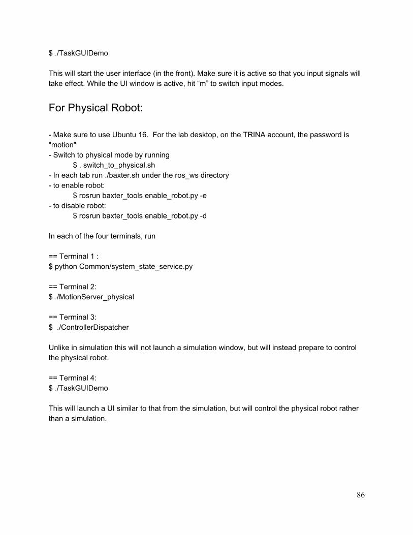
$ ./TaskGUIDemo This will start the user interface (in the front). Make sure it is active so that you input signals will take effect. While the UI window is active, hit “m” to switch input modes.
For Physical Robot: - Make sure to use Ubuntu 16. For the lab desktop, on the TRINA account, the password is "motion" - Switch to physical mode by running
$ . switch_to_physical.sh - In each tab run ./baxter.sh under the ros_ws directory - to enable robot:
$ rosrun baxter_tools enable_robot.py -e - to disable robot:
$ rosrun baxter_tools enable_robot.py -d In each of the four terminals, run == Terminal 1 : $ python Common/system_state_service.py == Terminal 2: $ ./MotionServer_physical == Terminal 3: $ ./ControllerDispatcher Unlike in simulation this will not launch a simulation window, but will instead prepare to control the physical robot. == Terminal 4: $ ./TaskGUIDemo This will launch a UI similar to that from the simulation, but will control the physical robot rather than a simulation.
86

Appendix III: CAD Models
This section contains Solidworks drawings of critical parts and assemblies of both the
passive and active RoboPuppets
Passive RoboPuppet CAD Models
Full Assembly Exploded View
87

Model of Link with W0 and W1 joints
Common potentiometer assembly used in the S1, E1 and W1 joints
88
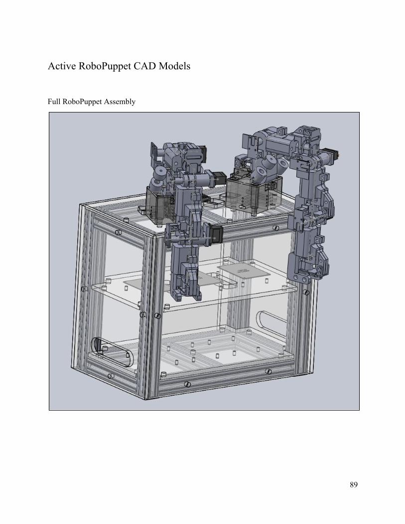
Active RoboPuppet CAD Models
Full RoboPuppet Assembly
89

Full Arm Assembly
90
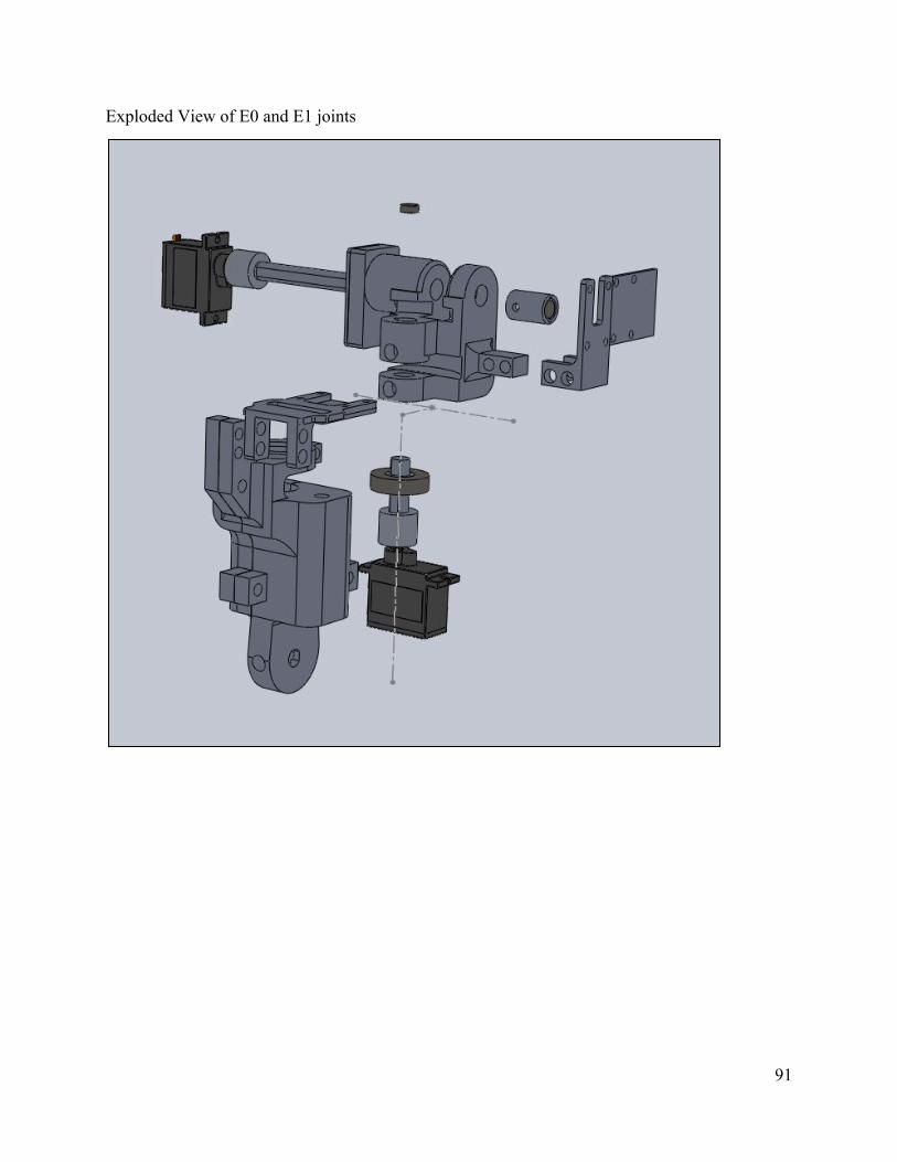
Exploded View of E0 and E1 joints
91

DH Parameter Wireframe
92

Appendix IV: Torque Calculations
It was necessary to acquire actuators that could apply sufficient joint torque in order to
perform gravity compensation. This spreadsheet is used to calculate the worst case scenario
torque that is applied to each joint. The assumptions were made that the arm is fully cantilevered
in the worst case scenario, that each joint would use the same motor, and that the s1 joint would
have the highest torque needed for gravity compensation. The spreadsheet calculates the mass of
each link as a function of its geometry, scale to Baxter, and part density. The number generated
by this spreadsheet was used as a constraint
93