Telemetry Adapter V1-0 - shop.jonathan.it · Page 3 / 24 Safety notes, meaning of symbols...
24
09/2016 Operating instructions Telemetry Adapter V1-0
Transcript of Telemetry Adapter V1-0 - shop.jonathan.it · Page 3 / 24 Safety notes, meaning of symbols...

09/2016 Operating instructions
Telemetry Adapter V1-0
Page 2 / 24
Table of Contents
SAFETY NOTES, MEANING OF SYMBOLS ................................................................................................................. 3
WARNINGS AND SAFETY INSTRUCTIONS ................................................................................................................ 4
EXCLUSION OF LIABILITY AND DAMAGES ................................................................................................................ 5
TELEMETRY ADAPTER V1-0, DESCRIPTION .............................................................................................................. 6
FUNCTIONAL PRINCIPLE ......................................................................................................................................................... 6
CONNECTION OF THE TELEMETRY ADAPTER TO THE ECU ........................................................................................ 7
CONNECTION TO THE ECU V6.0 ............................................................................................................................................. 7 CONNECTION TO THE ECU V10 .............................................................................................................................................. 8
Connection to the Futaba S.BUS2 receiver ................................................................................................................. 8 Connection to the Graupner HoTT receiver ................................................................................................................ 8 Connection to the Multiplex MSB receiver ................................................................................................................. 8
SETTING THE ECU TO THE DESIRED TELEMETRY PROVIDER/TYPE ............................................................................. 9
FUTABA S.BUS2 MODE ........................................................................................................................................ 10
REGISTERING THE JETCAT TELEMETRY ADAPTER AS NEW S.BUS2 SENSOR ON THE FUTABA TRANSMITTER ........................................... 10 Connections with transmitter method A .................................................................................................................. 10 Connections with transmitter method B .................................................................................................................. 11 Register process using the T18MZ as an example .................................................................................................... 12
CONNECTION OF THE JETCAT TELEMETRY ADAPTER TO THE S.BUS2 OF THE FUTABA RECEIVER ......................................................... 13 TRANSMITTED DATA (FUTABA S.BUS2 MODE) ........................................................................................................................ 14 EXAMPLE REPRESENTATION OF JETCAT TELEMETRY VALUES IN THE FUTABA TRANSMITTER T18MZ .................................................... 15 ...................................................................................................................................................................................... 15
GRAUPNER HOTT MODE ...................................................................................................................................... 16
CONNECTION OF THE JETCAT TELEMETRY ADAPTER TO A GRAUPNER HOTT RECEIVER ..................................................................... 16 TRANSMITTED DATA (GRAUPNER HOTT MODE) ....................................................................................................................... 17 EXAMPLE REPRESENTATION OF JETCAT TELEMETRY VALUES IN THE GRAUPNER MC32 TRANSMITTER T18MZ ...................................... 18
MULTIPLEX SENSOR BUS, MSB MODE .................................................................................................................. 21
CONNECTION OF THE JETCAT TELEMETRY ADAPTER TO A MULTIPLEX MSB RECEIVER ...................................................................... 21 DATA TRANSMITTED (MULTIPLEXED MSB MODE “MPX M-LINK1” FOR OLDER TRANSMITTERS) ....................................................... 21 EXAMPLE VIEWS OF TELEMETRY VALUES IN THE MULTIPLEX TRANSMITTER ..................................................................................... 22 DATA TRANSMITTED (MULTIPLEXED MSB MODE “MPX M-LINK2” FOR NEWER TRANSMITTERS) ...................................................... 23

Page 3 / 24
Safety notes, meaning of symbols
Attention!
This symbol highlights the following information that require the compliance of the user!
Any disregard for the adjacent instructions can impair the safety function as well as the
safety of the user himself.
Attention!
This symbol highlights limitation that require compliance by the user!
Any disregard for the adjacent limitations can impair the safety function as well
as the safety of the user himself.
This symbol highlights instructions, which should be strictly observed by the user to
ensure safe operation of the unit.
Attention!
Risk of fire and explosion!

Page 4 / 24
Warnings and safety instructions
WARNING!
Faults and defect during construction and or commissioning of the model can lead to injury
or even have fatal consequences.
ATTENTION!
Before you start operating a model air plane, you have to learn about the relevant legal
provisions. From a legal point of view, a flying model is an aircraft and is subject to the
relevant laws which have to be observed. The brochure “Luftrecht für Modellflieger”
(Air Traffic Law for Model Flyers) provides a summary of the German laws; it is also available
from specialist retailers. For models with jet engines an ascent permit must be available; in
addition there are insurance obligations. Postal regulations regarding radio control systems
also have to be observed. The regulations of the respective countries also have to be
adhered to.
WARNING!
The CAT JetCat model jet engines have been designed exclusively for model flying and are
not suitable for any other purpose. Any other use is not permitted, except solely for model
air plane flights since any other uses may lead to personal injury or death.
WARNING!
Any deviations from the instructions in this manual or of the respective manufacturer, the
use of other parts or materials and changes to the design which may have a negative effect
on the functioning and operational safety of the engine have to be avoided under all
circumstances.
Prior to starting a model, check all functions and all rudders and the reach of the remote
control while the remote control system is switched on without the antennae being
extended (or acc. to the remote control manufacturer requirements).
This operating check has to be repeated with the engine running and with all accessories.
The instructions for the radio control system also have to be observed.

Page 5 / 24
EXCLUSION OF LIABILITY AND DAMAGES
The adherence to the assembly and operating instructions in connection with the model and the
model jet engine as well as the installation, operation, use and maintenance of components
related to the model can not be supervised by CAT, M. Zipperer GmbH (hereinafter referred to as
“JetCat”). JetCat and its employees therefore assumes no liability for losses, damages or costs
resulting from the incorrect operation, erroneous behaviour or in any way with the above-
mentioned. If not otherwise regulated by law, the liability of JetCat to pay damages due the use of
the model, for whatever reasons, is excluded (incl. personal injury, death, damage to buildings and
damage due to loss of sales or business loss from trading interruption or other indirect or direct
consequential damages). The liability is regulated under all circumstances and in any case by the
legal regulation of the service contract.
THE COMMISSIONING AND OPERATION OF THE MODEL AND/OR the ENGINE NEXT TO ITS
ACCESSORIES TAKE PLACE AT THE SOLE RISK OF THE USER.
You affirm that JetCat cannot oversee and monitor that instructions for the setting up, operation,
use of the model aircraft, model jet engine and use of the radio control are followed. On the part
of JetCat, neither assurances, contractual agreements nor guarantees or other agreements have
been made to persons or companies in terms of functionality and commissioning of the model and
the model jet engine. In acquiring this model or model jet engine, you as user have relied on your
own expert knowledge and your own powers of judgement.

Page 6 / 24
Telemetry Adapter V1-0, description
The JetCat Telemetry Adapter allows the transmission of various ECU system values to the
telemetry system of different providers.
Presently supported telemetry providers:
• Multiplex Sensor Bus (MSB v2) (M-Link Telemetry)
• HoTTv4
• Futaba S.Bus
Functional principle
The JetCat Telemetry Adapter is connected directly to the ECU data bus.
The output of the Telemetry Adapter typically goes directly to the receiver (telemetry input of the
receiver). The sensor has two parallel switched outputs for the second output to be able to be
connected to another device or sensor.
The telemetry type (Multiplex MSB, Graupner/SJ HoTTv4, Futaba SBUS2) must be set in the engine
ECU using the GSU through the Limits menu (described on Page 9).
The data transmitted by the Telemetry Adapter to the receiver will depend on the telemetry type
selected.
Connection diagram of the
Telemetry Adapter to ECU V10.0

Page 7 / 24
Connection of the Telemetry Adapter to the ECU
Connection to the ECU V6.0
The software version of the ECU V6 must be at least V6.3S or higher!
Connection diagram to the LED board of a V6-ECU:
Connection to the ECU is done via
an 8-pin cable to the LED board

Page 8 / 24
Connection to the ECU V10
The software version of the ECU V10 must be at least V10.3S or higher!
Connection to the ECU is done via a 6-pin cable.
Attention: Do not accidentally plug in the 6-pin cable into the 8-pin bus connector of the
Telemetry Adapter!!!
Connection to the Futaba S.BUS2 receiver
Connection to the Graupner HoTT receiver
Connection to the Multiplex MSB receiver

Page 9 / 24
Setting the ECU to the desired telemetry provider/type
After the Telemetry Adapter is connected to the ECU, use the GSU to set the ECU to the desired
telemetry type. (Please refer to previous connection diagrams for your specific radio and ECU).
Proceed as follows:
• With the system completely connected (ECU, engine and receiver).
• Switch off ECU (� switch off receiver, if the display of the GSU is still active afterwards,
press the “Set” and “Run” button on the GSU at the same time. This will switch off the ECU
if it is in self holding mode.)
• Switch on ECU (� switch on receiver power supply)
• After the ECU has booted up, press the “Limits” button on the GSU (� Limits menu will
open).
• Now, using the “+/-” keys of the GSU scroll through the Limits menu until the parameter
“Telemetry” is displayed.
• Now, press and hold the “Change value” key on the GSU and using the +/- keys select one
of the following options: NOT USED (Telemetry switched off / not used) Futaba SBUS-2 (Futaba SBUS-2 Mode) Graupner HOTT (Graupner HOTTv4 Mode) MPX M-Link1 (Multiplex Sensor Bus, MSB Mode, old transmitter) Jeti (Jeti Mode, presently not usable!!!) MPX M-Link2 (Multiplex Sensor Bus, MSB Mode for new transmitter)
• Let go of the “Change value” key (� Telemetry Type is saved).
• Now completely switch off the ECU and switch on again. This activates the newly set
telemetry mode.
If correctly detected, the Telemetry Adapter
version number will automatically be shown.
Here: V7.8 connected
If it is not detected, “------”
is shown!

Page 10 / 24
Futaba S.BUS2 Mode
If Futaba S.BUS2 System is selected as the telemetry type, the JetCat telemetry sensor has to be
registered as a new sensor in the transmitter. The JetCat Telemetry Adapter will occupy 14 of the
32 possible sensor slots (= time slot) of the SBUS2 system.
Proceed as follows:
Registering the JetCat Telemetry Adapter as new S.BUS2 sensor on the Futaba transmitter
(The output of the Telemetry Adapter has to be connected to the programming jack of the
transmitter. Please refer T18MZ photo
First switch off the ECU by turning off the receiver!
To register the Telemetry Adapter as a new sensor, connect using one of two following methods:
Connections with transmitter method A
Power supply via the ECU
For this, the complete system must be wired with the ECU.
Only difference: The telemetry cable which usually goes to the receiver is being pulled and instead
plugged into the programming jack of the transmitter. There must not be any other connection of
this signal e.g. to a receiver!
After all connections have been provided, the receiver power supply can be switched on
� The ECU switches on � the Telemetry Adapter is supplied with power via the Bus connection
cable.

Page 11 / 24
Connections with transmitter method B
Power supply via separate battery (4.8-10 V)
For this, a suitable battery is connected to the second free output of the Telemetry Adapter, this
supplies the adapter with the required operational voltage.
The telemetry cable usually connected to the receiver is plugged in the programming jack intended
for the programming process on the transmitter.
There must not be any other connection of this signal e.g. to a receiver!
The ribbon cable to the ECU system does not have to be plugged in.
To the programming jack on
the transmitter
Page 12 / 24
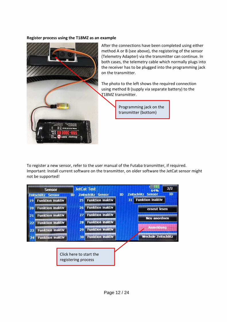
Register process using the T18MZ as an example
After the connections have been completed using either
method A or B (see above), the registering of the sensor
(Telemetry Adapter) via the transmitter can continue. In
both cases, the telemetry cable which normally plugs into
the receiver has to be plugged into the programming jack
on the transmitter.
The photo to the left shows the required connection
using method B (supply via separate battery) to the
T18MZ transmitter.
To register a new sensor, refer to the user manual of the Futaba transmitter, if required.
Important: Install current software on the transmitter, on older software the JetCat sensor might
not be supported!
Click here to start the
registering process
Programming jack on the
transmitter (bottom)

Page 13 / 24
After successful registration the overview of the registered sensors looks something like this or
similar:
As can be seen, in total 14 time slots are occupied.
Connection of the JetCat Telemetry Adapter to the S.BUS2 of the Futaba receiver
After the JetCat Telemetry Adapter has been successfully registered as a new sensor on the
transmitter, it can now be connected with the Futaba receiver:
Throttle
(= gas channel)

Page 14 / 24
Transmitted data (Futaba S.BUS2 mode)
The JetCat telemetry sensor sends the following values/information to the S.BUS2 telemetry
system:
Value/designation Remarks
Engine actual speed in rpm
EGT, Exhaust gas temperature in °C
Pump voltage in V
Engine set speed in rpm
Thrust in N
Remaining fuel in ml
Fuel consumption in ml/min
Flying height in m Only on ECU V10.0 or higher, otherwise 0
Fuel quality Only on P90-RXi /P140-RXi /P180-RXi
Voltage of engine battery in V
Current consumption Only on ECU V10.0 or higher, otherwise 0
Airspeed in km/h Only with the connected Airspeed sensor,
otherwise 0
Engine state and error codes
Speed of 2nd shaft Only on 2-shaft or helicopter engines

Page 15 / 24
Example representation of JetCat telemetry values in the Futaba transmitter T18MZ
For this, open the telemetry menu of the transmitter...

Page 16 / 24
Graupner HoTT Mode
After the Graupner HoTT mode is selected as the telemetry type, the JetCat Telemetry Adapter can
be connected to a suitable Graupner HoTT receiver.
The JetCat Telemetry Adapter logs on to the transmitter as “GAM module” (General Air Module).
Here, only the so-called graphic mode of GAM sensor type is used at the moment.
Connection of the JetCat Telemetry Adapter to a Graupner HoTT receiver
Throttle
(= gas channel)
Telemetry input of
the receiver Output of Telemetry Adapter.
Further sensors can be connected on the
second plug connection.

Page 17 / 24
Transmitted data (Graupner HoTT mode)
The JetCat Telemetry Adapter logs on to the transmitter as “GAM module” (General Engine
Module).
The following values/information is transmitted to the HoTT telemetry system:
Value/designation Remarks
Cell voltage 1-3 of the engine battery Only on engines with connected BMS (=Battery
Management System), otherwise display of 0
Voltage of engine battery in V
Pump voltage in V
EGT, Exhaust gas temperature in °C On temperatures below 220 °C the value in the
display of the transmitter is shown “unaltered”.
On real measurement values over 220 °C, the
displayed value is shown divided by a factor of 10.
The reason for this is that from the HoTT protocol
unfortunately only values between -20 and + 235 °C
are possible for temperature values.
To be able to show values above this range this
“trick” has been resorted too.
In practice, this means the following:
If the engine is switched off, the temperature is
displayed correctly (because the temperature will
probably always be below 220 °C).
When the engine is running, the value displayed
must be multiplied by 10 to obtain the real
temperature (for example, a display of 48 °C then
means effectively 480 °C exhaust gas temperature)
Ambient temperature in °C Temperature at front on the engine housing
Remaining fuel in % 0—100 %
Remaining fuel in ml
Engine actual speed in rpm
Flying height in m Only on ECU V10.0 or higher, otherwise 0
Current consumption Only on ECU V10.0 or higher, otherwise 0
Engine battery capacity in mAh Will be updated only in engines with generator
function, otherwise e.g. 2100 mAh
Airspeed in km/h Only with the connected Airspeed sensor,
otherwise 0
Speed of 2nd shaft Only on 2-shaft or helicopter engines, otherwise 0;
Will be transmitted but unfortunately is presently
not shown by the transmitter software!

Page 18 / 24
Example representation of JetCat telemetry values in the Graupner MC32 transmitter T18MZ
As already explained, the JetCat Telemetry Adapter simulates a Hott General Engine Module.
This produces the following images in the transmitter display showing the graphical telemetry
data. The JetCat Telemetry Adapter uses this fixed predetermined Graupner display screens to
visualize the operating data of a JetCat engine.
“ON” is shown if the engine is
running and the thrust control is in
the hands of the pilot
Flying altitude
Voltage of engine battery is
9.1 V
Current consumption from
the engine battery 0.1 A
Capacity engine battery
2100 mAh
Remaining fuel amount as
bar graph and text
Voltage engine battery
Pump voltage (1.9 V)
Engine exhaust gas
temperature
+58 means here effective
580 °C exhaust gas
temperature
Intake temperature +20 °C
Cell voltage of the engine
battery (only with BMS)
Turbine speed 83300 rpm

Page 19 / 24
Capacity engine battery
2100 mAh
Voltage engine battery
ins9.1 V
Voltage engine battery is
9.1 V
Current consumption from
the engine battery is 0.2 A
Capacity of engine battery
2100 mAh
Voltage of engine battery is
9.1 V
Exhaust gas temperature
580 °C
Remaining fuel amount as
bar graph and text

Page 20 / 24
Pump voltage 1.8 V
Engine speed: 96200 rpm
Maximum measured engine
speed: 124700 rpm
Measured flight speed via
air pressure sensor
(AirSpeed Sensor) 268 km/h
Intake temperature +20 °C

Page 21 / 24
Multiplex Sensor Bus, MSB Mode
Connection of the JetCat Telemetry Adapter to a Multiplex MSB receiver
The output of the Telemetry Adapter is connected with the telemetry input of the receiver.
More MSB sensors can be connected on the second (parallel) outputs of the Telemetry Adapter.
In this case, it should be noted that the JetCat Telemetry Adapter already occupies fixed the
addresses 3 to 14/15!
Data transmitted (Multiplexed MSB mode “MPX M-Link1” for older transmitters)
At the moment the following fixed MSB addresses and values assignments are used/occupied:
Address Value/designation Remarks
3 Engines actual speed in rpm
4 EGT, Exhaust gas temperature in °C
5 Pump voltage in V
6 Engine battery voltage in V An alarm is initiated during under-voltage
7 Current consumption
8 Battery capacity in mAh
(engine battery)
Will be updated only in engines with generator
function, otherwise display fixed on e.g. 2100 mAh
9 Remaining fuel in ml An alarm is initiated once the calculated
remaining fuel amount drops under the value
programmed in the ECUs Limits menu under
“Low Fuel Limit”.
10 Remaining fuel in % An alarm is initiated once the calculated
remaining fuel amount drops under the value
programmed in the ECUs Limits menu under
“Low Fuel Limit”.

Page 22 / 24
11 Speed of 2nd shaft Only on 2-shaft or helicopter engines
An alarm is issued once the sensor of the second
shaft has a fault
12 Flying height in m Only on ECU V10.0 or higher
13 Airspeed in km/h Only if the connected Airspeed sensor is active,
otherwise 0.
An alarm is initiated once the measured speed
exceeds the value programmed in the ECUs
Limits menu under “Max.AirSpeed”.
14 Internal engine state 0-3
0: OFF
1: Starting/cranking
2: At idle, it is waited that the stick
is moved to idle.
3: Normal operation
This value is shown as % LQI since the multiplex
system currently does not allow for clear text
display.
An alarm is initiated once the engine enters into
state “0” = OFF.
Example views of telemetry values in the Multiplex transmitter
Example: Alarm, since the speed was exceeded

Page 23 / 24
Data transmitted (Multiplexed MSB mode “MPX M-Link2” for newer transmitters)
At the moment the following fixed MSB addresses and values assignments are used/occupied:
Address Value/designation Remarks
3 Engines actual speed in rpm
4 EGT, Exhaust gas temperature in °C
5 Pump voltage in V
6 Engine battery voltage in V An alarm is initiated during under voltage
7 Current consumption
8 Battery capacity in mAh
(engine battery)
Will be updated only in engines with
generator function, otherwise display fixed on
e.g. 2100 mAh
9 Remaining fuel in ml An alarm is initiated once the calculated
remaining fuel amount drops under the value
programmed in the ECUs Limits menu under
“Low Fuel Limit”.
10 Remaining fuel in % An alarm is initiated once the calculated
remaining fuel amount drops under the value
programmed in the ECUs Limits menu under
“Low Fuel Limit”.
11 Speed of 2nd shaft Only on 2-shaft or helicopter engines
An alarm is issued once the sensor of the
second shaft has a fault
12 Flying height in m Only on ECU V10.0 or higher
13 Airspeed in km/h Only if the connected Airspeed sensor is active,
otherwise 0.
An alarm is initiated once the measured speed
exceeds the value programmed in the ECUs
Limits menu under “Max.AirSpeed”.
14 Internal engine state
Display in clear text in the telemetry display
An alarm is initiated once the engines enters
into state “0” = OFF.
15 Last reason for switching off Display in clear text in the telemetry display

Ingenieurbüro CAT, M. Zipperer GmbH
Wettelbrunnerstraße 6
D-79282 Staufen
Germany
Phone: + 49 (0) 76 34-5056-800
Fax: + 49 (0) 76 34-5056-802
www.jetcat.de