Telecommunication Network Present Trends and Future · april 27, 2014 zte corporation, nepal....
59
TELECOMMUNICATION NETWORKS PRESENT TRENDS AND FUTURE Sandeep Sharma Sandeep Sharma Engineer ZTE Corporation, Nepal April 27, 2014
Transcript of Telecommunication Network Present Trends and Future · april 27, 2014 zte corporation, nepal....

TELECOMMUNICATION NETWORKS PRESENT TRENDS AND FUTURE
Sandeep SharmaSandeep SharmaEngineerZTE Corporation, NepalApril 27, 2014

NETWORKNETWORK
• INFRASTRUCTURE THAT ALLOWS TWOINFRASTRUCTURE THAT ALLOWS TWO OR MORE HOSTS TO COMMUNICATE WITH EACH OTHERWITH EACH OTHER

INTERCONNECTION OF NODESINTERCONNECTION OF NODES

INFORMATIONINFORMATION
HOST HOSTINFO
VOICE

VOICE SIGNALVOICE SIGNAL
• Usable voice frequency band ranges fromUsable voice frequency band ranges from approximately 300 Hz to 3400 Hz
• Voice frequency transmission channel is• Voice-frequency transmission channel is usually 4 kHz, including guard bands
VOICE SIGNAL THROUGH NETWORKVOICE SIGNAL THROUGH NETWORK

FILTERING AND SAMPLING OF VOICE SIGNAL

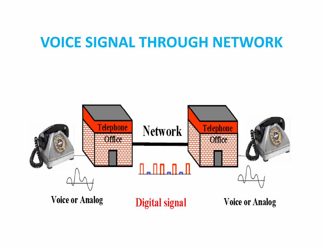
VOICE SIGNAL VOLTAGE ‘SAMPLED’ AT125 MICROSECONDS INTERVALS125 MICROSECONDS INTERVALS.
8000 TIMES PER SECOND

PULSE CODE MODULATIONPULSE CODE MODULATION
VOICE ENCODINGVOICE TO PAM TO PCM ‐ 8‐BIT WORD

DIGITAL SIGNALSDIGITAL SIGNALS
Fundamental digital signal in• Fundamental digital signal in telecommunications
• Building block of most of all other signals


Time Division Multiplexing ‐ TDMTime Division Multiplexing TDM

MULTIPLEXINGMULTIPLEXING
• The basic concept of multiplexing is toThe basic concept of multiplexing is to integrate traffic on a common channel for efficient utilization of the transmission linkefficient utilization of the transmission link

CATEGORIES OF MULTIPLEXINGCATEGORIES OF MULTIPLEXING
– Space division multiplexing (SDM)
– Frequency division multiplexing (FDM)
– Time division multiplexing (TDM)
– Wavelength division multiplexing (WDM)

SPACE DIVISION MULTIPLEXING (SDM)(SDM)
• SDM is the simplest (and crudest) form ofSDM is the simplest (and crudest) form of multiplexing
• Usually combined with other multiplexing• Usually combined with other multiplexing techniques

FREQUENCY DIVISION MULTIPLEXING (FDM)MULTIPLEXING (FDM)

FREQUENCY DIVISION MULTIPLEXING (FDM)

TIME DIVISIONMULTIPLEXING (TDM)TIME DIVISION MULTIPLEXING (TDM)
• TDM allows multiple channels to be usedTDM allows multiple channels to be used by allowing the channels to send data by taking turnstaking turns

TIME DIVISIONMULTIPLEXING (TDM)TIME DIVISION MULTIPLEXING (TDM)
• Time on the circuit h d llshared equally
• Each channel getting a specified timeslotspecified timeslot whether needed or not
• More efficient than FDM
• Since TDM doesn’t use guard bands, entireguard bands, entire capacity can be divided up between channels
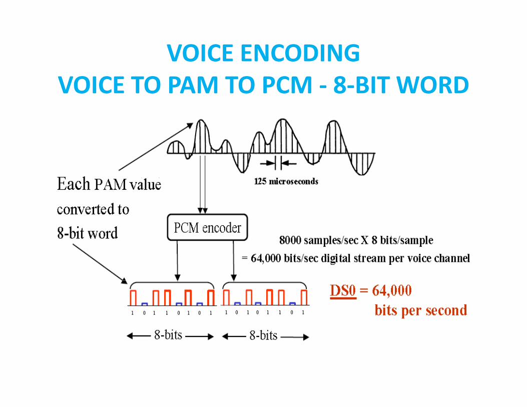
WAVE DIVISION MULTIPLEXING( )(WDM)

WAVE DIVISION MULTIPLEXING( )(WDM)

DWDM – FOUR WAVE LENGTH SYSTEM

WAVE DIVISION MULTIPLEXINGWAVE DIVISION MULTIPLEXING
• Wave Division Multiplexing is used to addWave Division Multiplexing is used to add another fiber optic system to the same set of fibers but with optic cards with differentof fibers, but with optic cards with different wavelengths
• DWDM adds many fiber systems to the• DWDM adds many fiber systems to the same set of fibers, with optic cards only 0 1 nm apart in wavelength0.1 nm apart in wavelength

WIDELY USED TRANSMISSION EQUIPMENT
• MICROWAVE• MICROWAVE• DWDM• DWDM• SDHSDH
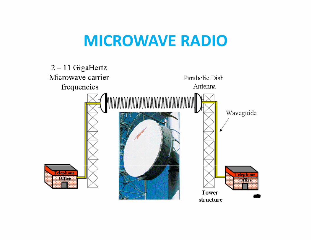
MICROWAVE RADIOMICROWAVE RADIO

WAVEGUIDEWAVEGUIDE

SDH OVERVIEWSDH OVERVIEW
• Limitation of PDH• Limitation of PDH• Advantages of SDH over• Advantages of SDH over
PDH

THE HISTORY OF DIGITAL TRANSMISSION
• ’70s - introduction of PCM into Telecom70s introduction of PCM into Telecom networks
• 32 PCM streams are Synchronously• 32 PCM streams are Synchronously Multiplexed to 2.048Mbit/s (E1)M lti l i t hi h t i PDH• Multiplexing to higher rates via PDH
• 1985 Bellcore proposes SONET• 1988 SDH standard introduced.

PDH: PLESIOCHRONOUS DIGITAL HIERARCHY
• Multiplex levels:Multiplex levels:2.048 Mbit/s8 448 Mbit/8.448 Mbit/s34.368 Mbit/s139.264 Mbit/s
PLESIOCHRONOUS MULTIPLEXINGPLESIOCHRONOUS MULTIPLEXING
• Before SDH transmission networks were based on the PDH hierarchy.
• Plesiochronous means nearly synchronous.2 Mbi / i i l l i l d• 2 Mbit/s service signals are multiplexed to 140 Mbit/s for transmission over optical fiber or radio.or radio.
• Multiplexing of 2 Mbit/s to 140 Mbit/s requires two intermediate multiplexing stages of 8 Mbit/ d 34 Mbit/Mbit/s and 34 Mbit/s.
• Alarm and performance management requires separate equipment in PDHrequires separate equipment in PDH.

PDH MULTIPLEXINGPDH MULTIPLEXING
• PDH Multiplexing of 2 Mbit/s to 140 Mbit/sPDH Multiplexing of 2 Mbit/s to 140 Mbit/s requires 22
• PDH multiplexers:• PDH multiplexers:16 x 2DME4 x 3DME1 x 4DME• Also a total of 106 cables required.
PDH ADD/DROPPDH ADD/DROP
• If a small number of 2 Mbit/s streamsIf a small number of 2 Mbit/s streams passing through a site need to be dropped then in PDH this requires large amount ofthen in PDH this requires large amount of equipment to multiplex down to 2Mbit/s.

WHAT IS SDH?WHAT IS SDH?
• The basis of Synchronous Digital HierarchyThe basis of Synchronous Digital Hierarchy (SDH) is synchronous multiplexing - data from multiple tributary sources is byte interleaved.p y y
• In SDH the multiplexed channels are in fixed locations relative to the framing byte.g y
• Demultiplexing is achieved by gating out the required bytes from the digital stream.
• This allows a single channel to be ‘dropped’ from the data stream without demultiplexing intermediate rates as is required in PDH.

SDH RATESSDH RATES
• SDH is a transport hierarchy based on p ymultiples of 155.52 Mbit/s
• The basic unit of SDH is STM-1:STM 1 155 52 Mbi /STM-1 = 155.52 Mbit/sSTM-4 = 622.08 Mbit/sSTM 16 2588 32 Mbit/STM-16 = 2588.32 Mbit/sSTM-64 = 9953.28 Mbit/s• Each rate is an exact multiple of the lower• Each rate is an exact multiple of the lower
rate therefore the hierarchy is synchronous.

COMPARISON: SIGNAL ADDING/DROPPING PROCESSES OF SDH & PDHPROCESSES OF SDH & PDH
Dem
ultiple
Multiplexiexing
Dem
ultiplexing
Dem
ultiple
Multiplexi
Multiplexing
ing
g exing
ing

CURRENT TRENDCURRENT TREND
STRIVING TO PROVIDE TRUE BROADBAND EXPERIENCEBROADBAND EXPERIENCE

MAJOR CHALLANGESMAJOR CHALLANGES

SWITHCHING MODEL EMPLOYED BY THE NODES
1 CIRCUIT SWITCHING1. CIRCUIT SWITCHINGIF HOST A WISHES TO COMMUNICATE WITH HOST B A ��������� ������������� WITH HOST B, A ��������� ������������� ���� IS ALLOCATED BETWEEN A AND B
2 PACKET SWITCHING2. PACKET SWITCHINGDATA IS ������� ���� ������� WHICH ARE SENT FROM A TO B VIA INTERMEDIATESENT FROM A TO B VIA INTERMEDIATE NODES

• CIRCUIT• CIRCUIT MODE COMMUNICATION– BANDWIDTH RESERVATION
• PACKETPACKET MODE COMMUNICATION
STATISTICA MU TIP EXINGTDM i i i– STATISTICAL MULTIPLEXINGTDM is circuit mode communication

STATISTICAL MULTIPLEXINGSTATISTICAL MULTIPLEXING
• traffic burstiness• peak to average rate • A circuit-switched network would conservatively
allocate to each source a capacity equal to its peakallocate to each source a capacity equal to its peak rate
• In this case, full resource utilization takes place only when all of the sources transmit at their peak rateswhen all of the sources transmit at their peak rates
• This is typically a low-probability event • A statistical multiplexer, however, allocates a capacity
that lies between the average and peak rates andthat lies between the average and peak rates and buffers the traffic during periods when demand exceeds channel capacity

DRAWBACKSDRAWBACKS
• INFLEXIBLE BANDWIDTH SCALABILITYINFLEXIBLE BANDWIDTH SCALABILITY– When a service provider or enterprise needs
to add bandwidth they either bond multipleto add bandwidth, they either bond multiple circuits together or upgrade their network and equipment to support a new technologygy
– HIGH CapEX AND OpEX• INFLEXIBLE BANDWIDTH OPTIONSINFLEXIBLE BANDWIDTH OPTIONS
– stair-step upgrade– TDM-based circuits are based on telephone-– TDM-based circuits are based on telephone-
centric technology and are only available in fixed bandwidth increments.

CHOICES FOR SERVICE PROVIDERCHOICES FOR SERVICE PROVIDER

ETHERNET TECHNOLOGYETHERNET TECHNOLOGY
• FLEXIBLE BANDWIDTH SCALABILITYFLEXIBLE BANDWIDTH SCALABILITY• FLEXIBLE BANDWIDTH OPTION
GREATLY REDUCES CAPEX AND OPEX• GREATLY REDUCES CAPEX AND OPEX

PTNPTN

PSEUDOWIREPSEUDOWIRE
• All-IP is the trend of network and serviceAll IP is the trend of network and service development in the future.
• In this transition time many service modes• In this transition time, many service modes will coexist in the communication network, such as TDM service ATM service IPsuch as TDM service, ATM service, IP service and Ethernet servicePWE3 t h l i t b i th• PWE3 technology come into being as the situation requires. It becomes one of the
th d t l th bl i thmethods to solve the problem in the combination of traditional communication
t k d IP b t k

TUNNELTUNNEL
• Host X is sending packets to twoHost X is sending packets to two destinations. Both flows ingress into the network through label-switching router Anetwork through label switching router A (LSR A), which determines what label-switched path (LSP) to use for eachswitched path (LSP) to use for each packet and adds a label to the packet accordinglyaccordingly


TYPES OF ETHERNET SERVICESTYPES OF ETHERNET SERVICES

EPL SERVICEEPL SERVICE

EVPL SERVICEEVPL SERVICE
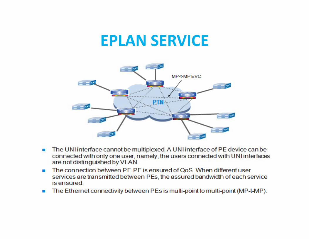
EPLAN SERVICEEPLAN SERVICE
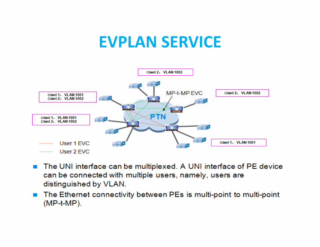
EVPLAN SERVICEEVPLAN SERVICE

EPTREE SERVICEEPTREE SERVICE

EVPTREE SERVICEEVPTREE SERVICE

TMP, LSP(TUNNEL) PROTECTIONTMP, LSP(TUNNEL) PROTECTION
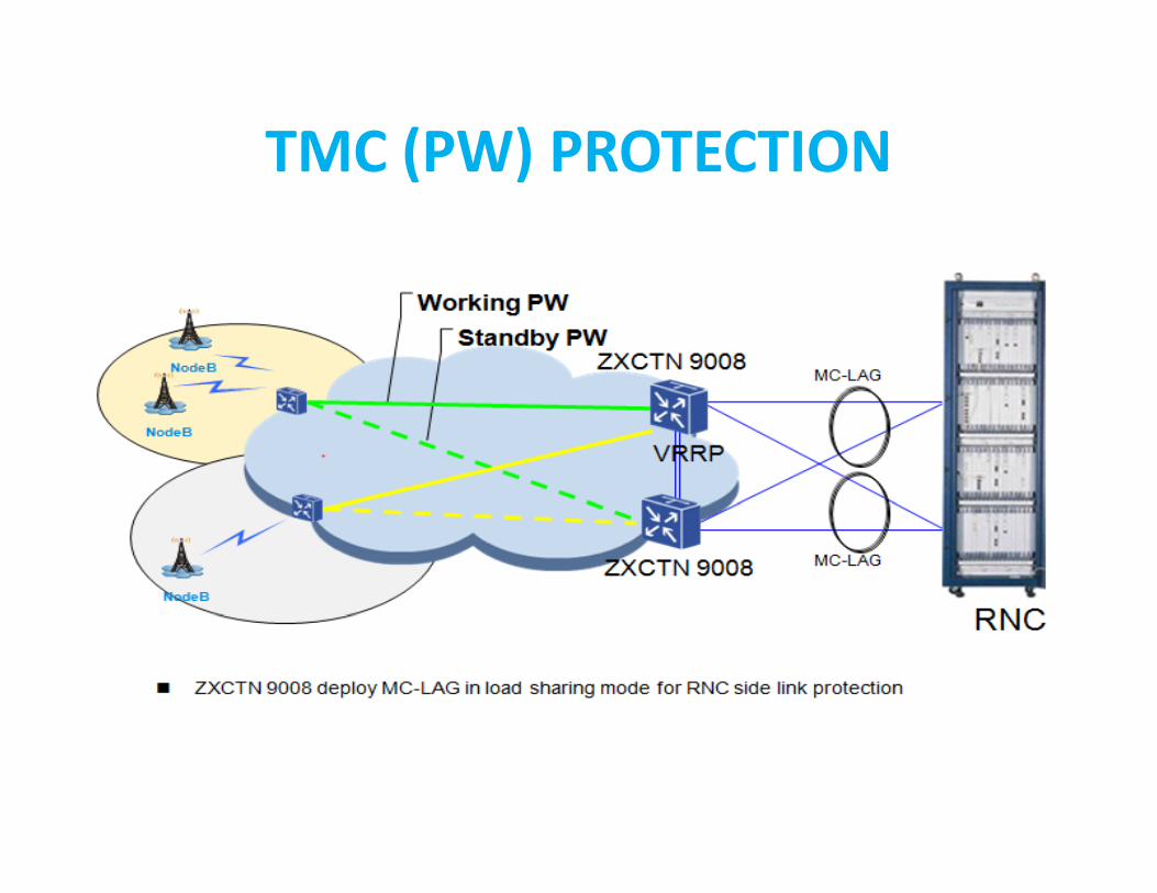
TMC (PW) PROTECTIONTMC (PW) PROTECTION

CASE STUDY‐MOBILE OPERATORCASE STUDY MOBILE OPERATOR


![ZTE Warp Connect - zte- · PDF file[sprint_ZTE_ZTE Warp Connect_ug _en_030317_d1] TOC i ... available LTE network connection. Your device searches for and makes a connection automatically](https://static.fdocuments.in/doc/165x107/5a7403827f8b9aea3e8b92ba/zte-warp-connect-zte-a-sprintztezte-warp-connectug-en030317d1-toc.jpg)