TELECOM/DATACOM - Carling Techthat meet all current datacom/telecom industry performance and design...
132
TELECOM/DATACOM CATALOG Circuit Protection
Transcript of TELECOM/DATACOM - Carling Techthat meet all current datacom/telecom industry performance and design...
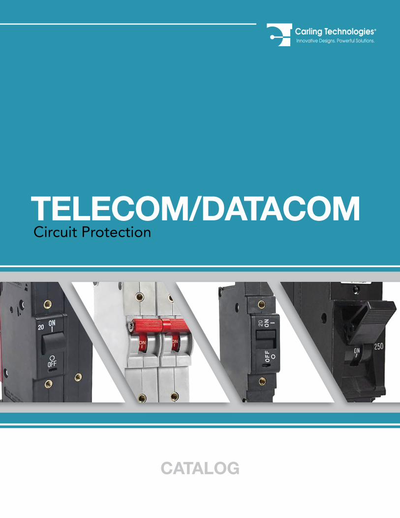
TELECOM/DATACOM
CATALOG
Circuit Protection
......
......
......
.
......
......
......
......
......
......
......
......
......
......
......
......
......
......
......
......
......
......
......
...
......
......
......
.
• Rocker• Toggle• Pushbutton• Rotary
• PDU’s• Keypads• Control Modules
INFOUNDED
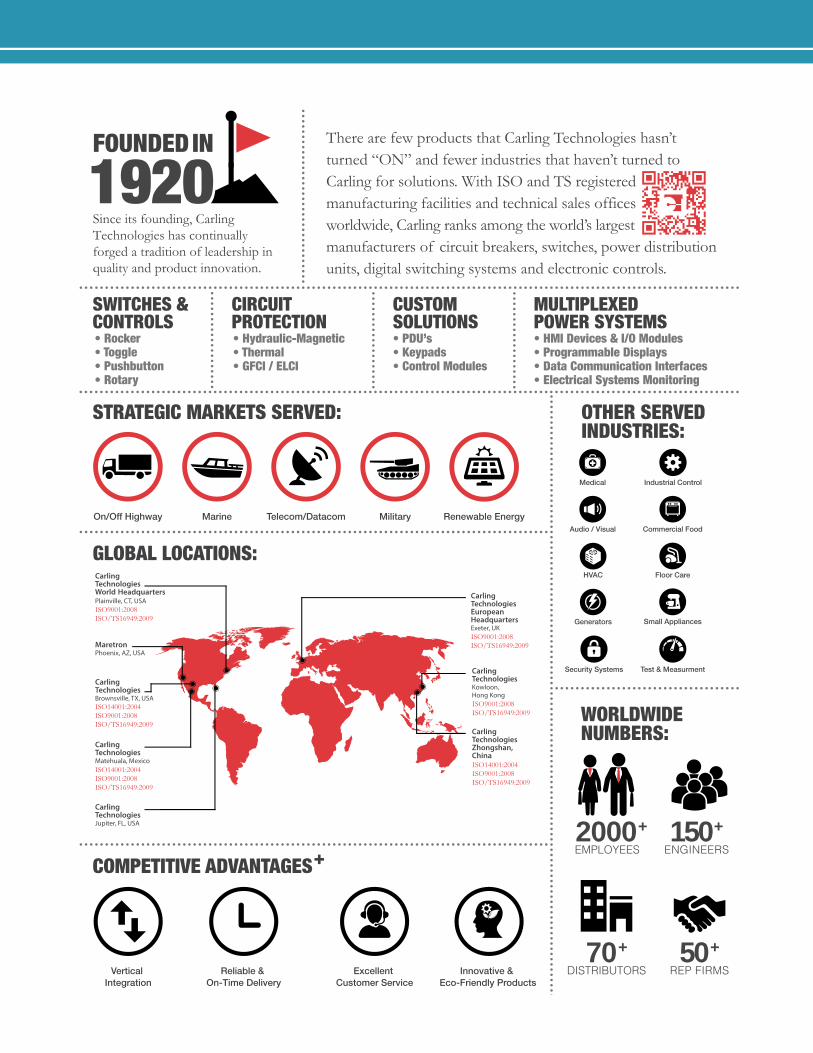
Since its founding, Carling Technologies has continually forged a tradition of leadership in quality and product innovation.
ISO9001:2008ISO/TS16949:2009
ISO9001:2008ISO/TS16949:2009
ISO9001:2008ISO/TS16949:2009
ISO14001:2004ISO9001:2008ISO/TS16949:2009
ISO14001:2004ISO9001:2008ISO/TS16949:2009
ISO14001:2004ISO9001:2008ISO/TS16949:2009
There are few products that Carling Technologies hasn’t turned “ON” and fewer industries that haven’t turned to Carling for solutions. With ISO and TS registered manufacturing facilities and technical sales officesworldwide, Carling ranks among the world’s largest manufacturers of circuit breakers, switches, power distribution units, digital switching systems and electronic controls.
STRATEGIC MARKETS SERVED:
COMPETITIVE ADVANTAGES+
OTHER SERVEDINDUSTRIES:
WORLDWIDENUMBERS:
SWITCHES &CONTROLS
CIRCUIT PROTECTION• Hydraulic-Magnetic• Thermal• GFCI / ELCI
CUSTOMSOLUTIONS
GLOBAL LOCATIONS:
150ENGINEERS
+
1920
2000EMPLOYEES
+
REP FIRMS50+
DISTRIBUTORS70+
On/Off Highway Marine Telecom/Datacom Military Renewable Energy
Medical Industrial Control
Audio / Visual Commercial Food
HVAC Floor Care
Generators Small Appliances
Test & MeasurmentSecurity Systems
Vertical Integration
Reliable & On-Time Delivery
Excellent Customer Service
Innovative & Eco-Friendly Products
......
......
......
.
• HMI Devices & I/O Modules• Programmable Displays• Data Communication Interfaces• Electrical Systems Monitoring
MULTIPLEXEDPOWER SYSTEMS
1www.carlingtech.com
Telecom/Datacom Circuit Protection
pageProduct Selector Guide.......................................................2
N-Series ................................................................................ 4L-Series ............................................................................... 11CX-Series ............................................................................ 17M-Series ............................................................................. 25A-Series .............................................................................. 44B-Series .............................................................................. 64TB-Series ............................................................................ 81J-Series .............................................................................. 85C-Series .............................................................................. 91F-Series .............................................................................111
Time Delay Values ...........................................................121Custom Power Distribution Units .................................126
Table of ContentsCarling Technologies offers a full line of innovative, high-performance and reliable circuit breakers that meet all current datacom/telecom industry performance and design requirements insuring continued services and maximum circuit protection.
These circuit breakers are ideally suited for the rigors and confined spaces found in today’s telecom/datacom power distribution units and rack systems. In other words, Carling circuit breakers protect against unnecessary power outages while providing design features that exceed today’s expectations.
Within This Catalog, you will find comprehensive product information for each product series including applications, specifications and ordering schemes.
Available Online are tools such as part configurator, product selectors and stock checks. For the latest information on all our products, please visit www.carlingtech.com
Application Solution Engineers are readily available to assist you in selecting the appropriate product for your application. For further assistance, please email us at [email protected]
© 2017 Carling Technologies, Inc. Carling Technologies is a registered trademark of Carling Technologies, Inc. in the U.S. and other countries.
www.carlingtech.com2
Product Selector Guide
*Options and approvals shown may apply to specific construction combinations only, consult factory for clarification.Manufacturer reserves the right to change product specifications without prior notice.
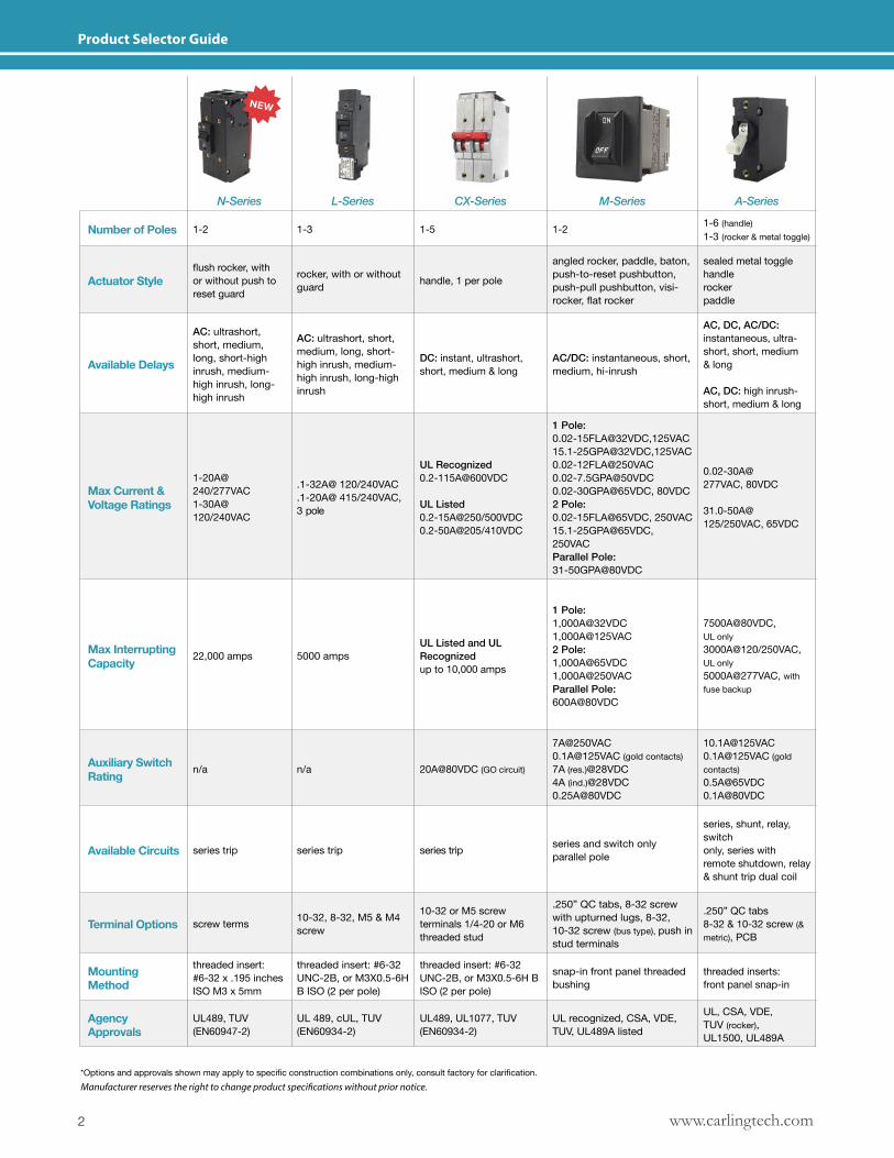
N-Series L-Series CX-Series M-Series A-Series
Number of Poles 1-2 1-3 1-5 1-2 1-6 (handle) 1-3 (rocker & metal toggle)
Actuator Styleflush rocker, with or without push to reset guard
rocker, with or without guard handle, 1 per pole
angled rocker, paddle, baton, push-to-reset pushbutton, push-pull pushbutton, visi-rocker, flat rocker
sealed metal toggle handle rocker paddle
Available Delays
AC: ultrashort, short, medium, long, short-high inrush, medium-high inrush, long-high inrush
AC: ultrashort, short, medium, long, short-high inrush, medium-high inrush, long-high inrush
DC: instant, ultrashort, short, medium & long
AC/DC: instantaneous, short, medium, hi-inrush
AC, DC, AC/DC: instantaneous, ultra-short, short, medium & long
AC, DC: high inrush-short, medium & long
Max Current & Voltage Ratings
1-20A@ 240/277VAC1-30A@ 120/240VAC
.1-32A@ 120/240VAC
.1-20A@ 415/240VAC, 3 pole
UL Recognized 0.2-115A@600VDC
UL Listed 0.2-15A@250/500VDC 0.2-50A@205/410VDC
1 Pole:0.02-15FLA@32VDC,125VAC15.1-25GPA@32VDC,[email protected]@50VDC0.02-30GPA@65VDC, 80VDC2 Pole:0.02-15FLA@65VDC, 250VAC15.1-25GPA@65VDC, 250VACParallel Pole:31-50GPA@80VDC
0.02-30A@277VAC, 80VDC
31.0-50A@125/250VAC, 65VDC
Max Interrupting Capacity 22,000 amps 5000 amps
UL Listed and UL Recognizedup to 10,000 amps
1 Pole: 1,000A@32VDC1,000A@125VAC2 Pole:1,000A@65VDC1,000A@250VACParallel Pole:600A@80VDC
7500A@80VDC, UL only3000A@120/250VAC, UL only5000A@277VAC, with fuse backup
Auxiliary Switch Rating n/a n/a 20A@80VDC (GO circuit)
[email protected]@125VAC (gold contacts)7A (res.)@28VDC4A (ind.)@28VDC0.25A@80VDC
[email protected]@125VAC (gold contacts)[email protected]@80VDC
Available Circuits series trip series trip series trip series and switch only parallel pole
series, shunt, relay, switchonly, series with remote shutdown, relay & shunt trip dual coil
Terminal Options screw terms 10-32, 8-32, M5 & M4 screw
10-32 or M5 screw terminals 1/4-20 or M6 threaded stud
.250” QC tabs, 8-32 screw with upturned lugs, 8-32, 10-32 screw (bus type), push in stud terminals
.250” QC tabs8-32 & 10-32 screw (& metric), PCB
Mounting Method
threaded insert: #6-32 x .195 inches ISO M3 x 5mm
threaded insert: #6-32 UNC-2B, or M3X0.5-6H B ISO (2 per pole)
threaded insert: #6-32 UNC-2B, or M3X0.5-6H B ISO (2 per pole)
snap-in front panel threaded bushing
threaded inserts: front panel snap-in
Agency Approvals
UL489, TUV (EN60947-2)
UL 489, cUL, TUV (EN60934-2)
UL489, UL1077, TUV (EN60934-2)
UL recognized, CSA, VDE, TUV, UL489A listed
UL, CSA, VDE, TUV (rocker),UL1500, UL489A
3www.carlingtech.com
*Options and approvals shown may apply to specific construction combinations only, consult factory for clarification.
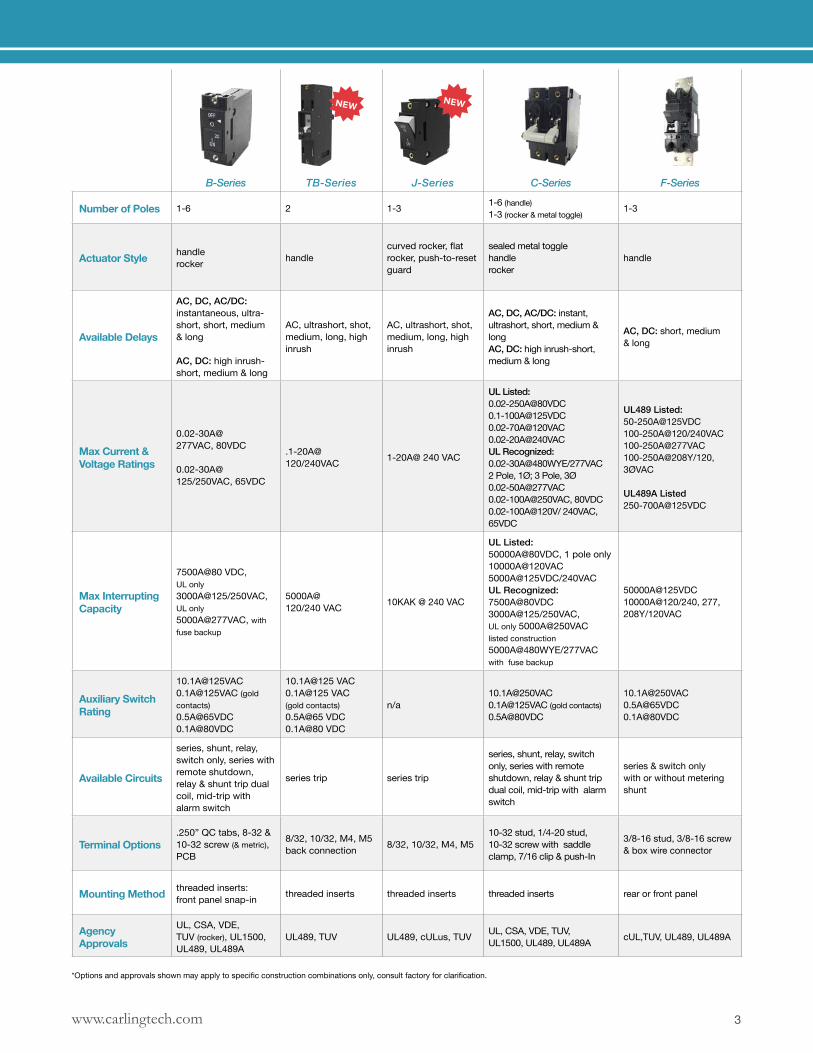
B-Series TB-Series J-Series C-Series F-Series
Number of Poles 1-6 2 1-3 1-6 (handle)1-3 (rocker & metal toggle)
1-3
Actuator Style handle rocker handle
curved rocker, flat rocker, push-to-reset guard
sealed metal toggle handle rocker
handle
Available Delays
AC, DC, AC/DC: instantaneous, ultra-short, short, medium & long
AC, DC: high inrush-short, medium & long
AC, ultrashort, shot, medium, long, high inrush
AC, ultrashort, shot, medium, long, high inrush
AC, DC, AC/DC: instant, ultrashort, short, medium & longAC, DC: high inrush-short, medium & long
AC, DC: short, medium & long
Max Current & Voltage Ratings
0.02-30A@277VAC, 80VDC
0.02-30A@125/250VAC, 65VDC
.1-20A@120/240VAC 1-20A@ 240 VAC
UL Listed:[email protected]@[email protected]@240VACUL Recognized:0.02-30A@480WYE/277VAC 2 Pole, 1Ø; 3 Pole, 3Ø[email protected]@250VAC, 80VDC0.02-100A@120V/ 240VAC, 65VDC
UL489 Listed:50-250A@125VDC100-250A@120/240VAC100-250A@277VAC100-250A@208Y/120, 3ØVAC
UL489A Listed250-700A@125VDC
Max Interrupting Capacity
7500A@80 VDC, UL only3000A@125/250VAC, UL only5000A@277VAC, with fuse backup
5000A@120/240 VAC 10KAK @ 240 VAC
UL Listed:50000A@80VDC, 1 pole only10000A@120VAC5000A@125VDC/240VACUL Recognized:7500A@80VDC3000A@125/250VAC, UL only 5000A@250VAC listed construction 5000A@480WYE/277VAC with fuse backup
50000A@125VDC10000A@120/240, 277, 208Y/120VAC
Auxiliary Switch Rating
[email protected]@125VAC (gold contacts)[email protected]@80VDC
10.1A@125 VAC0.1A@125 VAC (gold contacts)0.5A@65 VDC0.1A@80 VDC
n/[email protected]@125VAC (gold contacts)0.5A@80VDC
[email protected]@65VDC0.1A@80VDC
Available Circuits
series, shunt, relay, switch only, series with remote shutdown, relay & shunt trip dual coil, mid-trip with alarm switch
series trip series trip
series, shunt, relay, switch only, series with remote shutdown, relay & shunt trip dual coil, mid-trip with alarm switch
series & switch onlywith or without metering shunt
Terminal Options.250” QC tabs, 8-32 & 10-32 screw (& metric), PCB
8/32, 10/32, M4, M5 back connection 8/32, 10/32, M4, M5
10-32 stud, 1/4-20 stud,10-32 screw with saddle clamp, 7/16 clip & push-In
3/8-16 stud, 3/8-16 screw & box wire connector
Mounting Method threaded inserts: front panel snap-in threaded inserts threaded inserts threaded inserts rear or front panel
Agency Approvals
UL, CSA, VDE, TUV (rocker), UL1500, UL489, UL489A
UL489, TUV UL489, cULus, TUV UL, CSA, VDE, TUV,UL1500, UL489, UL489A cUL,TUV, UL489, UL489A
www.carlingtech.com4
N-Series Circuit Breaker - Introduction
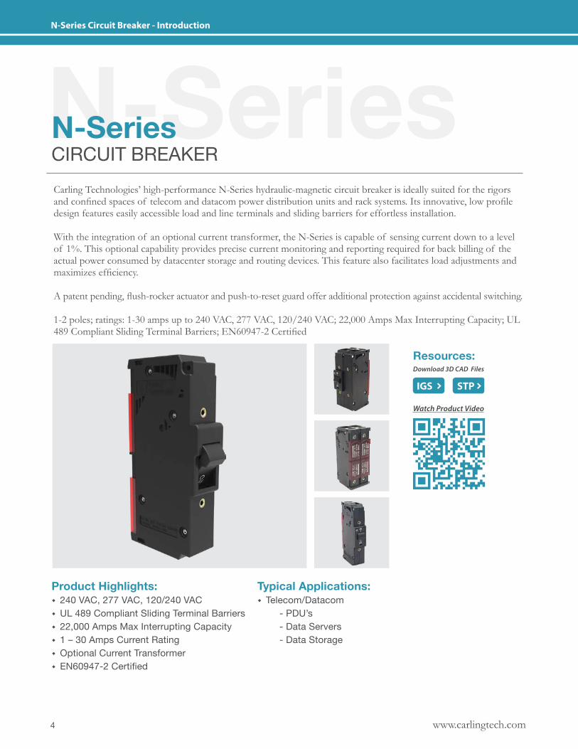
N-SeriesN-SeriesCIRCUIT BREAKERCarling Technologies’ high-performance N-Series hydraulic-magnetic circuit breaker is ideally suited for the rigors and confined spaces of telecom and datacom power distribution units and rack systems. Its innovative, low profile design features easily accessible load and line terminals and sliding barriers for effortless installation.
With the integration of an optional current transformer, the N-Series is capable of sensing current down to a level of 1%. This optional capability provides precise current monitoring and reporting required for back billing of the actual power consumed by datacenter storage and routing devices. This feature also facilitates load adjustments and maximizes efficiency.
A patent pending, flush-rocker actuator and push-to-reset guard offer additional protection against accidental switching.
1-2 poles; ratings: 1-30 amps up to 240 VAC, 277 VAC, 120/240 VAC; 22,000 Amps Max Interrupting Capacity; UL 489 Compliant Sliding Terminal Barriers; EN60947-2 Certified
Product Highlights: � 240 VAC, 277 VAC, 120/240 VAC � UL 489 Compliant Sliding Terminal Barriers � 22,000 Amps Max Interrupting Capacity � 1 – 30 Amps Current Rating � Optional Current Transformer � EN60947-2 Certified
Typical Applications: � Telecom/Datacom - PDU’s - Data Servers - Data Storage
IGS
Resources:Download 3D CAD Files
IGS STP
Watch Product Video
5www.carlingtech.com
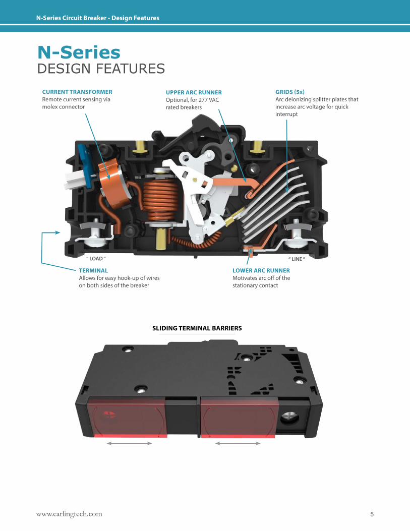
N-Series Circuit Breaker - Design Features
TERMINAL Allows for easy hook-up of wires on both sides of the breaker
“ LOAD “ “ LINE “
CURRENT TRANSFORMERRemote current sensing via molex connector
UPPER ARC RUNNEROptional, for 277 VAC rated breakers
GRIDS (5x)Arc deionizing splitter plates that increase arc voltage for quick interrupt
LOWER ARC RUNNERMotivates arc off of thestationary contact
SLIDING TERMINAL BARRIERS
N-SeriesDESIGN FEATURES
www.carlingtech.com6
N-Series Circuit Breaker - General Specifications
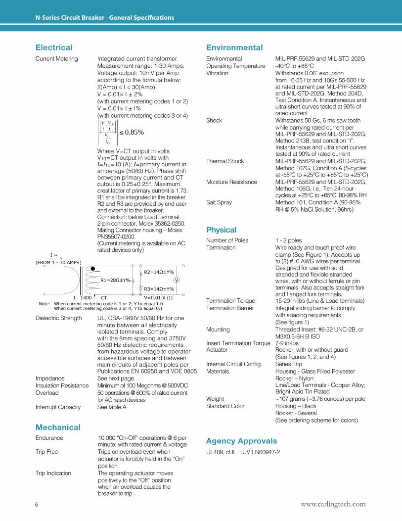
ElectricalCurrent Metering Integrated current transformer. Measurement range: 1-30 Amps. Voltage output: 10mV per Amp according to the formula below: 2(Amp)≤I≤30(Amp) V = 0.01× I ± 2% (with current metering codes 1 or 2) V = 0.01× I ±1% (with current metering codes 3 or 4)
%85.010
10
10
10
I
V
I
V
I
V
Where V=CT output in volts V10=CT output in volts with I=I10=10 (A); I=primary current in amperage (50/60 Hz). Phase shift between primary current and CT output is 0.25±0.25°. Maximum crest factor of primary current is 1.73. R1 shall be integrated in the breaker. R2 and R3 are provided by end user and external to the breaker. Connection: below Load Terminal. 2-pin connector, Molex 35362-0250. Mating Connector housing – Molex PN35507-0200. (Current metering is available on AC rated devices only)
I ~(FROM 1 - 30 AMPS)
R3=14Ω±Y%
V=0.01 X (I)
V
R2=14Ω±Y%
R1=28Ω±Y%
I : 1400 CTNote: Whencurrentmeteringcodeis1or2;Ytoequal1.0 Whencurrentmeteringcodeis3or4;Ytoequal0.1
Dielectric Strength UL, CSA-1960V 50/60 Hz for one minute between all electrically isolated terminals. Comply with the 8mm spacing and 3750V 50/60 Hz dielectric requirements from hazardous voltage to operator accessible surfaces and between main circuits of adjacent poles per Publications EN 60950 and VDE 0805Impedance See next pageInsulation Resistance Minimum of 100 Megohms @ 500VDCOverload 50 operations @ 600% of rated current for AC rated devices Interrupt Capacity See table A
EnvironmentalEnvironmental MIL-PRF-55629 and MIL-STD-202G Operating Temperature -40°C to +85°C Vibration Withstands 0.06” excursion from 10-55 Hz and 10Gs 55-500 Hz at rated current per MIL-PRF-55629 and MIL-STD-202G, Method 204D, Test Condition A. Instantaneous and ultra-short curves tested at 90% of rated currentShock Withstands 50 Gs, 6 ms saw tooth while carrying rated current per MIL-PRF-55629 and MIL-STD-202G, Method 213B, test condition “I”. Instantaneous and ultra short curves tested at 90% of rated currentThermal Shock MIL-PRF-55629 and MIL-STD-202G, Method 107G, Condition A (5-cycles at -55ºC to +25ºC to +85ºC to +25ºC)Moisture Resistance MIL-PRF-55629 and MIL-STD-202G, Method 106G, i.e., Ten 24-hour cycles at +25°C to +65°C, 80-98% RHSalt Spray Method 101, Condition A (90-95% RH @ 5% NaCl Solution, 96hrs)
MechanicalEndurance 10,000 “On-Off” operations @ 6 per minute; with rated current & voltageTrip Free Trips on overload even when actuator is forcibly held in the “On” positionTrip Indication The operating actuator moves positively to the “Off” position when an overload causes the breaker to trip
Agency ApprovalsUL489, cUL, TUV EN60947-2
PhysicalNumber of Poles 1 - 2 polesTermination Wire ready and touch proof wire clamp (See Figure 1). Accepts up to (2) #10 AWG wires per terminal. Designed for use with solid, strandedandflexiblestranded wires, with or without ferrule or pin terminals. Also accepts straight fork andflangedforkterminals.Termination Torque 15-20 in-lbs (Line & Load terminals) Termination Barrier Integral sliding barrier to comply with spacing requirements (Seefigure1)Mounting Threaded Insert: #6-32 UNC-2B, or M3X0.5-6H B ISOInsert Termination Torque 7-9 in-lbsActuator Rocker, with or without guard (Seefigures1,2,and4)InternalCircuitConfig. Series TripMaterials Housing - Glass Filled Polyester Rocker – Nylon Line/Load Terminals - Copper Alloy; Bright Acid Tin PlatedWeight ~107 grams (~3.76 ounces) per poleStandard Color Housing – Black Rocker - Several (See ordering scheme for colors)
7www.carlingtech.com
N-Series Circuit Breaker - General Specifications
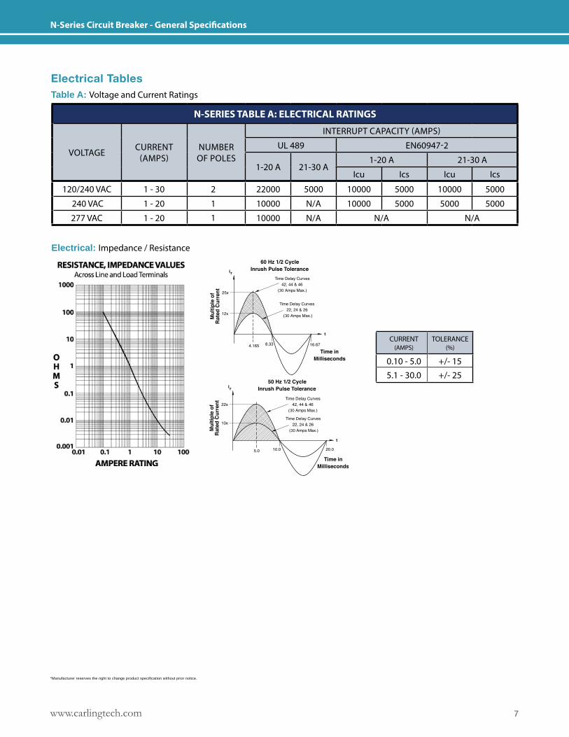
Electrical TablesTable A: Voltage and Current Ratings
N-SERIES TABLE A: ELECTRICAL RATINGS
VOLTAGE CURRENT (AMPS)
NUMBEROF POLES
INTERRUPT CAPACITY (AMPS)
UL 489 EN60947-2
1-20 A 21-30 A1-20 A 21-30 A
Icu Ics Icu Ics
120/240 VAC 1 - 30 2 22000 5000 10000 5000 10000 5000
240 VAC 1 - 20 1 10000 N/A 10000 5000 5000 5000
277 VAC 1 - 20 1 10000 N/A N/A N/A
Electrical: Impedance / Resistance
30
30
30
30
CURRENT (AMPS)
TOLERANCE (%)
0.10 - 5.0 +/- 155.1 - 30.0 +/- 25
*Manufacturer reserves the right to change product specification without prior notice.
www.carlingtech.com8
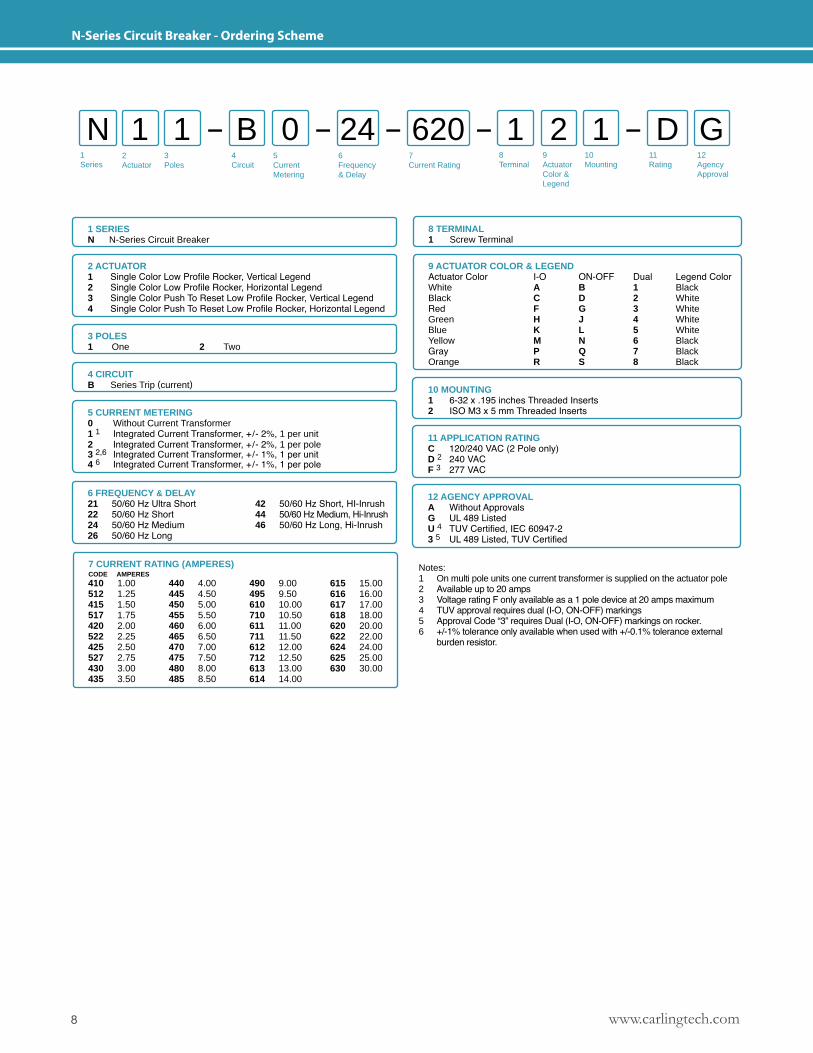
N-Series Circuit Breaker - Ordering Scheme
1Series
2Actuator
3Poles
5CurrentMetering
6Frequency& Delay
7Current Rating
8Terminal
9ActuatorColor &Legend
10Mounting
11Rating
12AgencyApproval
4 Circuit
N 1 B 1 11 0 2 D G24 620
1 SERIESN N-Series Circuit Breaker
2 ACTUATOR1 Single Color Low Profile Rocker, Vertical Legend2 Single Color Low Profile Rocker, Horizontal Legend3 Single Color Push To Reset Low Profile Rocker, Vertical Legend4 Single Color Push To Reset Low Profile Rocker, Horizontal Legend
8 TERMINAL1 Screw Terminal
3 POLES 1 One 2 Two
4 CIRCUITB Series Trip (current)
5 CURRENT METERING0 Without Current Transformer1 1 Integrated Current Transformer, +/- 2%, 1 per unit2 Integrated Current Transformer, +/- 2%, 1 per pole3 2,6 Integrated Current Transformer, +/- 1%, 1 per unit 4 6 Integrated Current Transformer, +/- 1%, 1 per pole
6 FREQUENCY & DELAY21 50/60 Hz Ultra Short22 50/60 Hz Short24 50/60 Hz Medium26 50/60 Hz Long
42 50/60 Hz Short, HI-Inrush 44 50/60 Hz Medium, Hi-Inrush46 50/60 Hz Long, Hi-Inrush
7 CURRENT RATING (AMPERES)CODE AMPERES410 1.00512 1.25415 1.50517 1.75420 2.00522 2.25425 2.50527 2.75430 3.00435 3.50
440 4.00445 4.50450 5.00455 5.50460 6.00465 6.50470 7.00475 7.50480 8.00485 8.50
490 9.00495 9.50610 10.00710 10.50611 11.00711 11.50612 12.00712 12.50613 13.00614 14.00
615 15.00616 16.00617 17.00618 18.00620 20.00622 22.00624 24.00625 25.00630 30.00
11 APPLICATION RATING C 120/240 VAC (2 Pole only)D 2 240 VACF 3 277 VAC
12 AGENCY APPROVALA Without ApprovalsG UL 489 ListedU 4 TUV Certified, IEC 60947-2 3 5 UL 489 Listed, TUV Certified
Notes: 1 On multi pole units one current transformer is supplied on the actuator pole2 Available up to 20 amps3 Voltage rating F only available as a 1 pole device at 20 amps maximum 4 TUV approval requires dual (I-O, ON-OFF) markings5 Approval Code “3” requires Dual (I-O, ON-OFF) markings on rocker.6 +/-1% tolerance only available when used with +/-0.1% tolerance external burden resistor.
10 MOUNTING1 6-32 x .195 inches Threaded Inserts2 ISO M3 x 5 mm Threaded Inserts
9 ACTUATOR COLOR & LEGENDActuator Color I-O ON-OFF Dual Legend ColorWhite A B 1 BlackBlack C D 2 WhiteRed F G 3 WhiteGreen H J 4 WhiteBlue K L 5 WhiteYellow M N 6 BlackGray P Q 7 BlackOrange R S 8 Black
9www.carlingtech.com
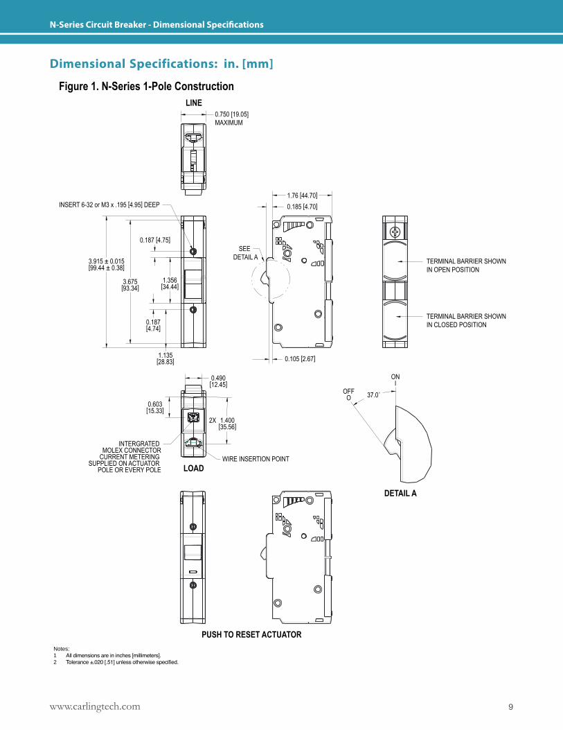
N-Series Circuit Breaker - Dimensional Specifications
INSERT 6-32 or M3 x .195 [4.95] DEEP
0.750 [19.05]MAXIMUM
LINE
Figure 1. N-Series 1-Pole Construction
LOAD
DETAIL A
0.105 [2.67]
SEE DETAIL A
1.76 [44.70]0.185 [4.70]
TERMINAL BARRIER SHOWNIN OPEN POSITION
TERMINAL BARRIER SHOWNIN CLOSED POSITION
0.187 [4.75]
1.356[34.44]3.675
[93.34]
3.915 ± 0.015[99.44 ± 0.38]
0.187[4.74]
1.135[28.83]
0.490[12.45]
1.400[35.56]
0.603[15.33]
2X
WIRE INSERTION POINT
INTERGRATED MOLEX CONNECTOR
CURRENT METERING SUPPLIED ON ACTUATOR
POLE OR EVERY POLE
OFFO
ONI
37.0˚
PUSH TO RESET ACTUATORNotes: 1 All dimensions are in inches [millimeters].2 Tolerance ±.020 [.51] unless otherwise specified.
Dimensional Specifications: in. [mm]
www.carlingtech.com10
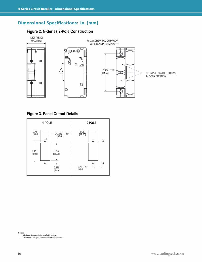
N-Series Circuit Breaker - Dimensional Specifications
Figure 3. Panel Cutout Details
1 POLE 2 POLE
TERMINAL BARRIER SHOWNIN OPEN POSITION
1.500 [38.10]MAXIMUM
2.962 [75.23]
TYP
#8-32 SCREW TOUCH PROOFWIRE CLAMP TERMINAL
0.75[19.05]
0.75[19.05]
0.75[19.05]
0.156[3.96]
TYP
1.38[35.05]
1.73[43.94]
0.175[4.45]
TYP
Figure 2. N-Series 2-Pole Construction
Notes: 1 All dimensions are in inches [millimeters].2 Tolerance ±.020 [.51] unless otherwise specified.
Dimensional Specifications: in. [mm]

11www.carlingtech.com
L-Series Circuit Breaker - Introduction
L-SeriesL-SeriesCIRCUIT BREAKERThe L-Series high performance, compact hydraulic- magnetic circuit breaker is ideally suited for the rigors and confined spaces found in today’s telecom/datacom power distribution units and rack systems. It provides best in class performance in an innovative low profile, space saving package complementing the overall spatial objectives required by telecommunications and data-communications systems designers in their quest to reduce the overall size of equipment, while increasing transmission capacity.
With the integration of an optional current transformer, the L-Series is capable of sensing current down to a level of 1%. This optional capability provides precise current monitoring and reporting required for back billing of the actual power consumed by datacenter storage and routing devices. This feature also facilitates load adjustments and maximizes efficiency.
Further, a patent pending flush rocker actuator design and optional push-to-reset guard offers additional protection against accidental switching.
Number of poles: 1-3 poles;. Max current/voltage ratings: .1-32A, 120/240-240VAC. Max interrupting capacity: 5000 Amps
Product Highlights: � Optional current transformer � Ultra low profile design saves valuable space � Optional handle guard actuator � UL 489 LISTED Branch Circuit breaker � Designed for worldwide datacenter compatibility with up to 240VAC ratings
Typical Applications: � Telecom/Datacom
Resources:Download 3D CAD Files
Watch Product Video
IGS STP
www.carlingtech.com12
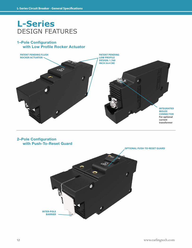
L-Series Circuit Breaker - General Specifications
1–Pole Configuration with Low Profile Rocker Actuator
2–Pole Configuration with Push-To-Reset Guard
PATENT PENDING FLUSH ROCKER ACTUATOR
OPTIONAL PUSH-TO-RESET GUARD
INTER-POLEBARRIER
PATENT PENDING LOW PROFILE DESIGN: 1.760 INCH (4.4 CM)
INTEGRATED MOLEX CONNECTORFor optional current transformer
L-SeriesDESIGN FEATURES
13www.carlingtech.com
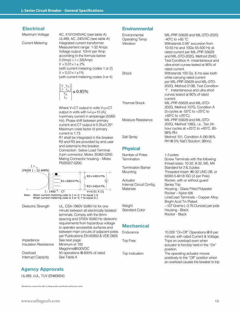
L-Series Circuit Breaker - General Specifications
*Manufacturer reserves the right to change product specification without prior notice.
Maximum Voltage AC, 415Y/240VAC (see table A) UL489, AC, 240VAC (see table A)Current Metering Integrated current transformer. Measurement range: 1-32 Amps Voltage output: 10mV per Amp according to the formula below: 2(Amp)≤I≤32(Amp) V = 0.01× I ± 2% (with current metering codes 1 or 2) V = 0.01× I ±1% (with current metering codes 3 or 4)
%85.010
10
10
10
I
V
I
V
I
V
Where V=CT output in volts V10=CT output in volts with I=I10=10 (A); I=primary current in amperage (50/60 Hz). Phase shift between primary current and CT output is 0.25±0.25°. Maximum crest factor of primary current is 1.73. R1 shall be integrated in the breaker. R2 and R3 are provided by end user and external to the breaker. Connection: below Load Terminal. 2-pin connector, Molex 35362-0250. Mating Connector housing – Molex PN35507-0200.
I ~(FROM 1 - 32 AMPS)
R3=14Ω±Y%
V=0.01 X (I)
V
R2=14Ω±Y%
R1=28Ω±Y%
I : 1400 CTNote: Whencurrentmeteringcodeis1or2;Ytoequal1.0 Whencurrentmeteringcodeis3or4;Ytoequal0.1
Dielectric Strength UL, CSA-1960V 50/60 Hz for one minute between all electrically isolated terminals. Comply with the 8mm spacing and 3750V 50/60 Hz dielectric requirements from hazardous voltage to operator accessible surfaces and between main circuits of adjacent poles per Publications EN 60950 & VDE 0805Impedance See next pageInsulation Resistance Minimum of 100 Megohms@500VDCOverload 50 operations @ 600% of ratedInterrupt Capacity See Table A
Electrical EnvironmentalEnvironmental MIL-PRF-55629 and MIL-STD-202GOperating Temp -40ºC to +85 ºC Vibration Withstands 0.06” excursion from 10-55 Hz and 10Gs 55-500 Hz at rated current per MIL-PRF-55629 and MIL-STD-202G, Method 204D, Test Condition A. Instantaneous and ultra-short curves tested at 90% of rated current.Shock Withstands 100 Gs, 6 ms saw tooth while carrying rated current per MIL-PRF-55629 and MIL-STD- 202G, Method 213B, Test Condition “I”. Instantaneous and ultra short curves tested at 90% of rated current.Thermal Shock MIL-PRF-55629 and MIL-STD- 202G, Method 107G, Condition A (5-cycles at -55ºC to +25ºC to +85ºC to +25ºC).Moisture Resistance MIL-PRF-55629 and MIL-STD- 202G, Method 106G, i.e., Ten 24- hour cycles at +25ºC to +65ºC, 80- 98% RH.Salt Spray Method 101, Condition A (90-95% RH @ 5% NaCl Solution, 96hrs)
PhysicalNumber of Poles 1-3 polesTermination Screw Terminals with the following thread sizes: 10-32, 8-32, M5, M4Termination Barrier Standard for 2 & 3 polesMounting Threaded Insert: #6-32 UNC-2B, or M3X0.5-6H B ISO (2 per Pole)Actuator Rocker, with or without guardInternalCircuitConfig. SeriesTripMaterials Housing - Glass Filled Polyester Rocker – Nylon 6/6 Line/Load Terminals – Copper Alloy; Bright Acid Tin Plated Weight ~107 Grams (~3.76 Ounces) per poleStandard Color Housing - Black Rocker - Black
MechanicalEndurance 10,000 “On-Off” Operations @ 6 per minute; with rated Current & Voltage.Trip Free Trips on overload even when actuator is forcibly held in the “On” position.Trip Indication The operating actuator moves positively to the “Off” position when an overload causes the breaker to trip
Agency ApprovalsUL489, cUL, TUV (EN60934)
www.carlingtech.com14
L-Series Circuit Breaker - General Specifications
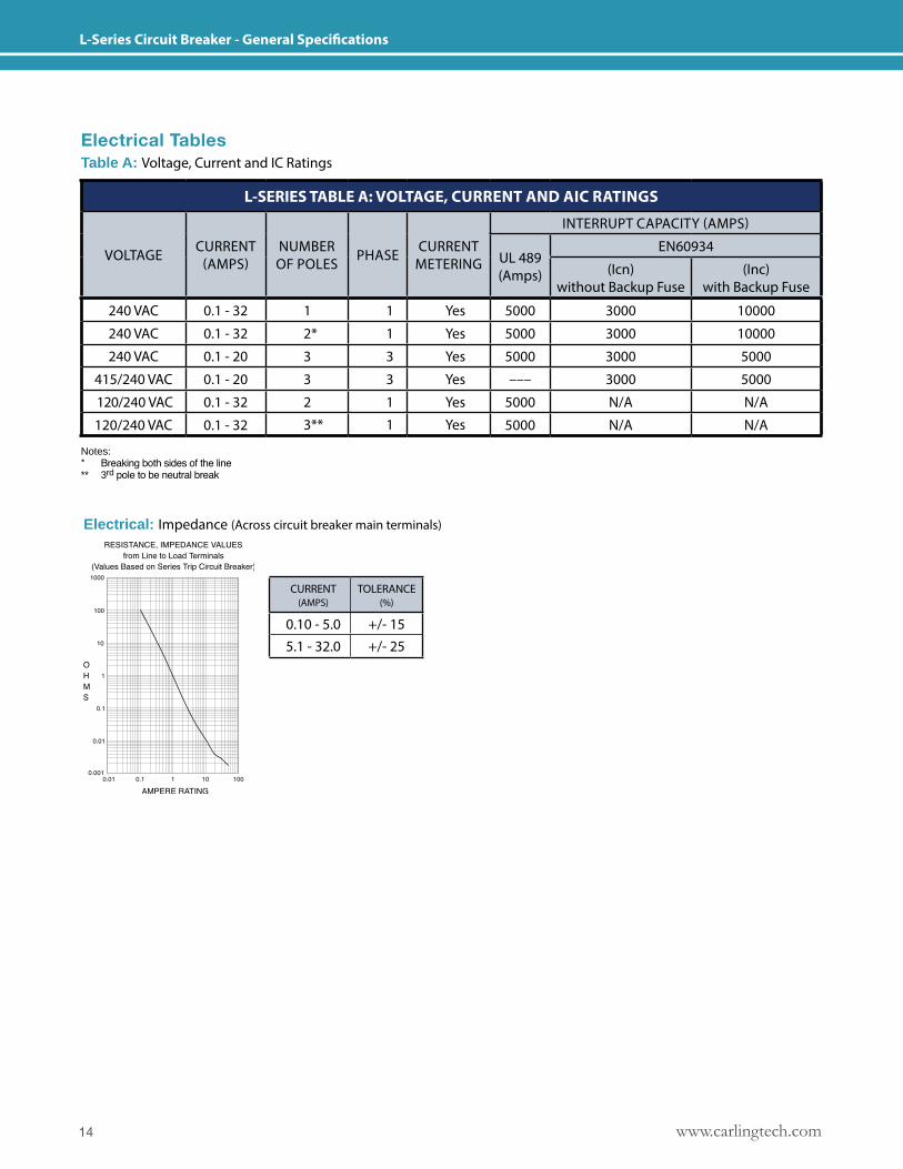
Electrical TablesTable A: Voltage, Current and IC Ratings
Electrical: Impedance (Across circuit breaker main terminals)
Notes:* Breaking both sides of the line** 3rd pole to be neutral break
CURRENT (AMPS)
TOLERANCE (%)
0.10 - 5.0 +/- 155.1 - 32.0 +/- 25
L-SERIES TABLE A: VOLTAGE, CURRENT AND AIC RATINGS
VOLTAGE CURRENT (AMPS)
NUMBEROF POLES PHASE CURRENT
METERING
INTERRUPT CAPACITY (AMPS)
UL 489 (Amps)
EN60934
(Icn) without Backup Fuse
(Inc)with Backup Fuse
240 VAC 0.1 - 32 1 1 Yes 5000 3000 10000
240 VAC 0.1 - 32 2* 1 Yes 5000 3000 10000
240 VAC 0.1 - 20 3 3 Yes 5000 3000 5000
415/240 VAC 0.1 - 20 3 3 Yes ––– 3000 5000
120/240 VAC 0.1 - 32 2 1 Yes 5000 N/A N/A
120/240 VAC 0.1 - 32 3** 1 Yes 5000 N/A N/A
15www.carlingtech.com
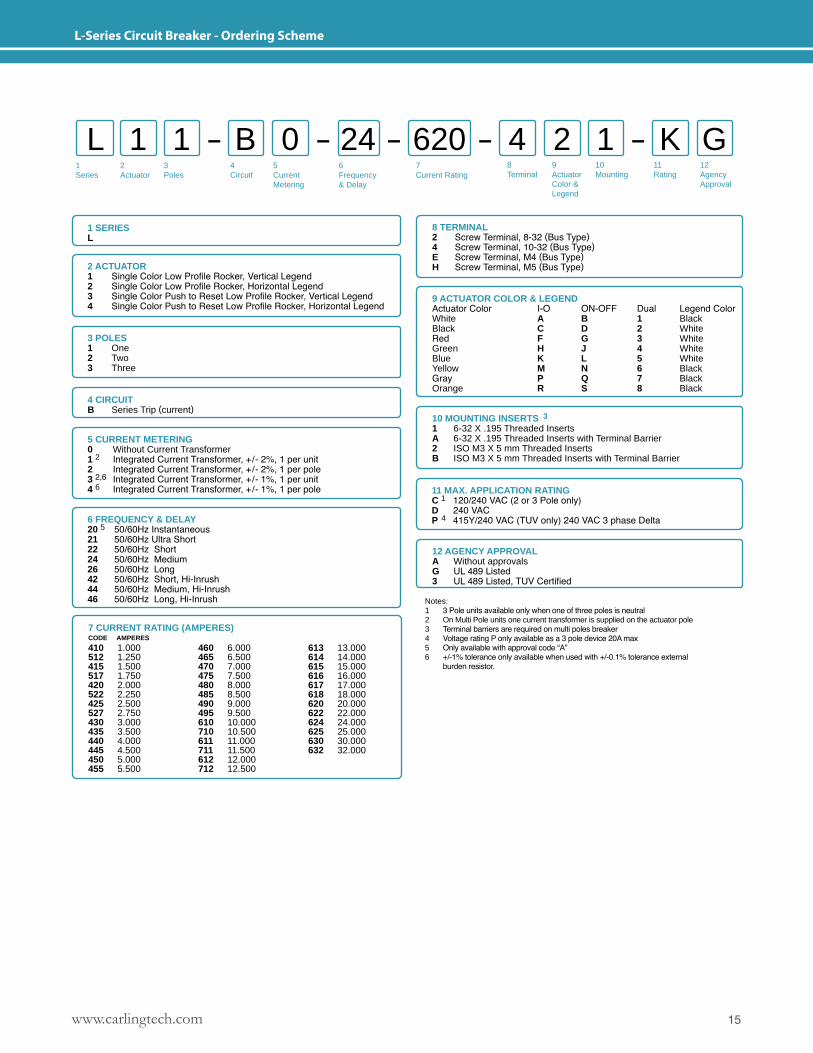
L-Series Circuit Breaker - Ordering Scheme
1Series
2Actuator
3Poles
5CurrentMetering
6Frequency& Delay
7Current Rating
8Terminal
12AgencyApproval
4 Circuit
L 1 B 4 11 0 2 GK24 620
1 SERIESL
2 ACTUATOR1 Single Color Low Profile Rocker, Vertical Legend2 Single Color Low Profile Rocker, Horizontal Legend3 Single Color Push to Reset Low Profile Rocker, Vertical Legend4 Single Color Push to Reset Low Profile Rocker, Horizontal Legend
8 TERMINAL2 Screw Terminal, 8-32 (Bus Type)4 Screw Terminal, 10-32 (Bus Type)E Screw Terminal, M4 (Bus Type)H Screw Terminal, M5 (Bus Type)
10 MOUNTING INSERTS 3
1 6-32 X .195 Threaded InsertsA 6-32 X .195 Threaded Inserts with Terminal Barrier2 ISO M3 X 5 mm Threaded InsertsB ISO M3 X 5 mm Threaded Inserts with Terminal Barrier
3 POLES 1 One2 Two 3 Three
4 CIRCUITB Series Trip (current)
5 CURRENT METERING0 Without Current Transformer1 2 Integrated Current Transformer, +/- 2%, 1 per unit2 Integrated Current Transformer, +/- 2%, 1 per pole3 2,6 Integrated Current Transformer, +/- 1%, 1 per unit 4 6 Integrated Current Transformer, +/- 1%, 1 per pole
6 FREQUENCY & DELAY20 5 50/60Hz Instantaneous21 50/60Hz Ultra Short22 50/60Hz Short24 50/60Hz Medium26 50/60Hz Long42 50/60Hz Short, Hi-Inrush44 50/60Hz Medium, Hi-Inrush46 50/60Hz Long, Hi-Inrush
7 CURRENT RATING (AMPERES) CODE AMPERES
410 1.000512 1.250415 1.500517 1.750420 2.000522 2.250425 2.500527 2.750430 3.000435 3.500440 4.000445 4.500450 5.000455 5.500
460 6.000465 6.500470 7.000475 7.500480 8.000485 8.500490 9.000495 9.500610 10.000710 10.500611 11.000711 11.500612 12.000712 12.500
613 13.000614 14.000615 15.000616 16.000617 17.000618 18.000620 20.000622 22.000624 24.000625 25.000630 30.000632 32.000
11 MAX. APPLICATION RATING C 1 120/240 VAC (2 or 3 Pole only)D 240 VACP 4 415Y/240 VAC (TUV only) 240 VAC 3 phase Delta
12 AGENCY APPROVALA Without approvalsG UL 489 Listed3 UL 489 Listed, TUV Certified
9 ACTUATOR COLOR & LEGENDActuator Color I-O ON-OFF Dual Legend ColorWhite A B 1 BlackBlack C D 2 WhiteRed F G 3 WhiteGreen H J 4 WhiteBlue K L 5 WhiteYellow M N 6 BlackGray P Q 7 BlackOrange R S 8 Black
9ActuatorColor &Legend
10Mounting
11Rating
Notes:1 3 Pole units available only when one of three poles is neutral2 On Multi Pole units one current transformer is supplied on the actuator pole3 Terminal barriers are required on multi poles breaker4 Voltage rating P only available as a 3 pole device 20A max5 Only available with approval code “A”6 +/-1% tolerance only available when used with +/-0.1% tolerance external burden resistor.
www.carlingtech.com16
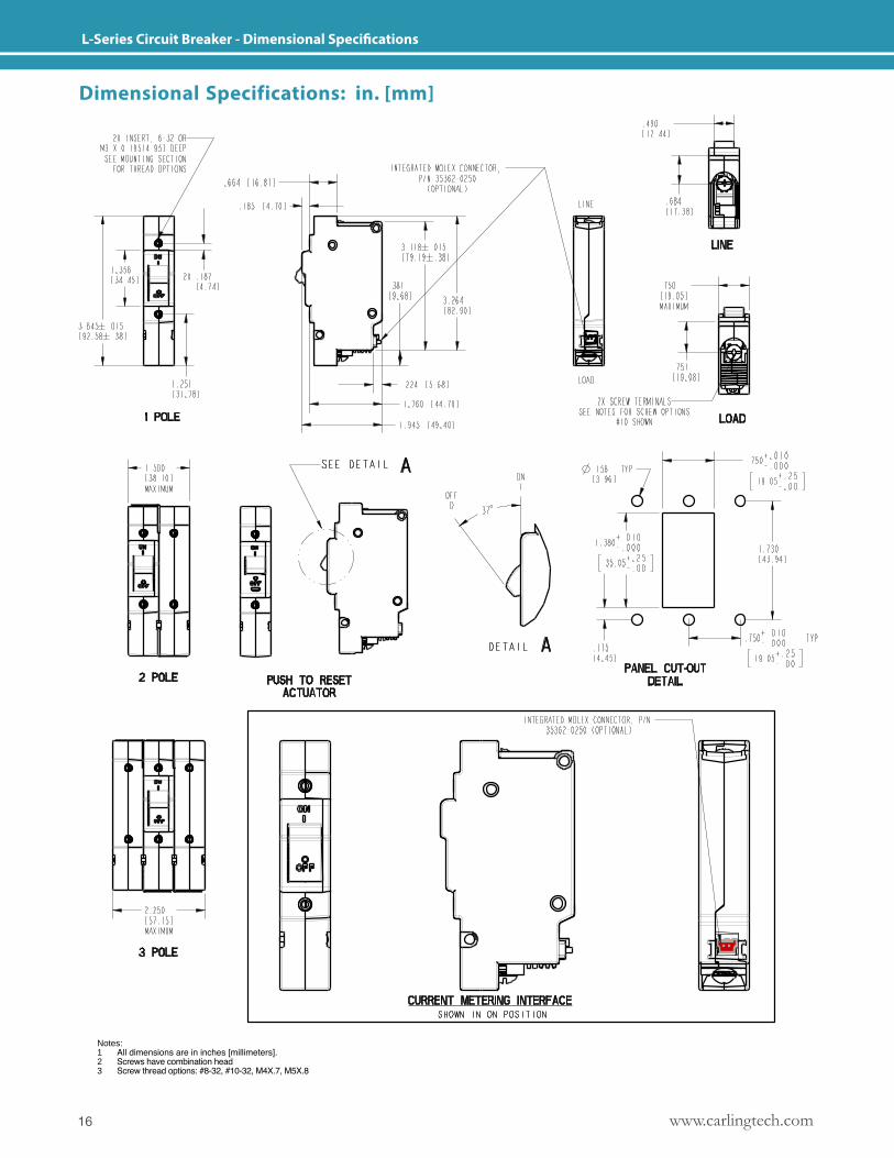
L-Series Circuit Breaker - Dimensional Specifications
Notes: 1 All dimensions are in inches [millimeters].2 Screws have combination head3 Screw thread options: #8-32, #10-32, M4X.7, M5X.8
Dimensional Specifications: in. [mm]
17www.carlingtech.com
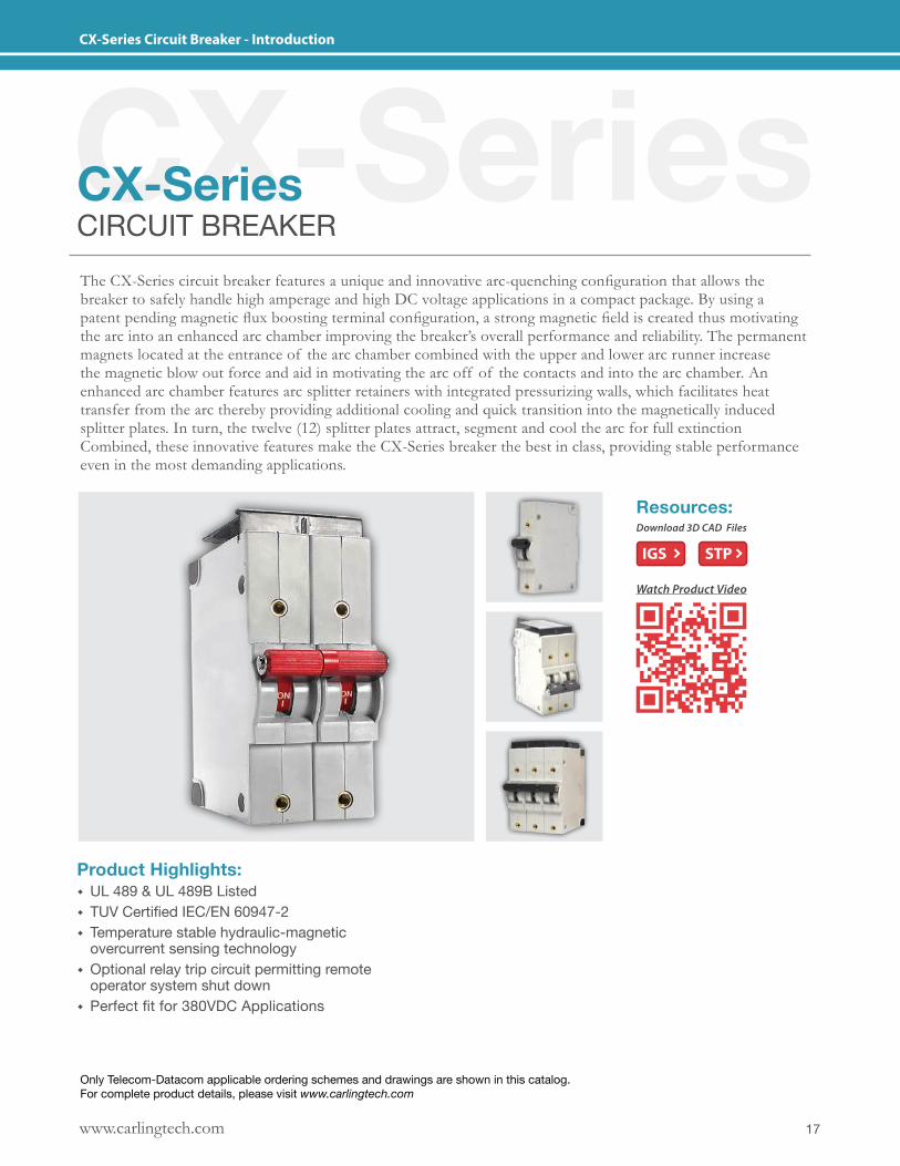
CX-Series Circuit Breaker - Introduction
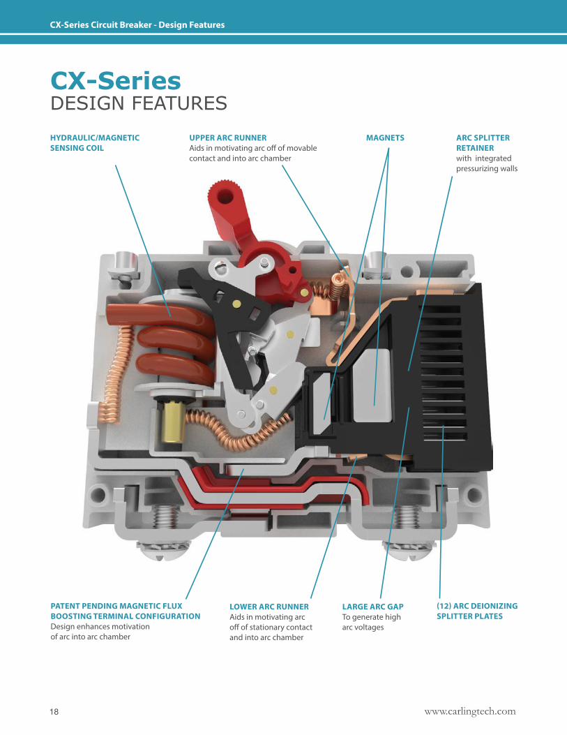
CX-SeriesCX-SeriesCIRCUIT BREAKERThe CX-Series circuit breaker features a unique and innovative arc-quenching configuration that allows the breaker to safely handle high amperage and high DC voltage applications in a compact package. By using a patent pending magnetic flux boosting terminal configuration, a strong magnetic field is created thus motivating the arc into an enhanced arc chamber improving the breaker’s overall performance and reliability. The permanent magnets located at the entrance of the arc chamber combined with the upper and lower arc runner increase the magnetic blow out force and aid in motivating the arc off of the contacts and into the arc chamber. An enhanced arc chamber features arc splitter retainers with integrated pressurizing walls, which facilitates heat transfer from the arc thereby providing additional cooling and quick transition into the magnetically induced splitter plates. In turn, the twelve (12) splitter plates attract, segment and cool the arc for full extinction Combined, these innovative features make the CX-Series breaker the best in class, providing stable performance even in the most demanding applications.
Product Highlights: � UL 489 & UL 489B Listed � TUV Certified IEC/EN 60947-2 � Temperature stable hydraulic-magnetic overcurrent sensing technology
� Optional relay trip circuit permitting remote operator system shut down
� Perfect fit for 380VDC Applications
Resources:Download 3D CAD Files
IGS STP
Watch Product Video
Only Telecom-Datacom applicable ordering schemes and drawings are shown in this catalog. For complete product details, please visit www.carlingtech.com
www.carlingtech.com18
CX-Series Circuit Breaker - Design Features
UPPER ARC RUNNER Aids in motivating arc off of movable contact and into arc chamber
PATENT PENDING MAGNETIC FLUX BOOSTING TERMINAL CONFIGURATION Design enhances motivation of arc into arc chamber
HYDRAULIC/MAGNETICSENSING COIL
ARC SPLITTER RETAINERwith integrated pressurizing walls
LOWER ARC RUNNERAids in motivating arc off of stationary contact and into arc chamber
LARGE ARC GAPTo generate high arc voltages
(12) ARC DEIONIZINGSPLITTER PLATES
MAGNETS
CX-SeriesDESIGN FEATURES
19www.carlingtech.com
CX-Series Circuit Breaker - General Specifications
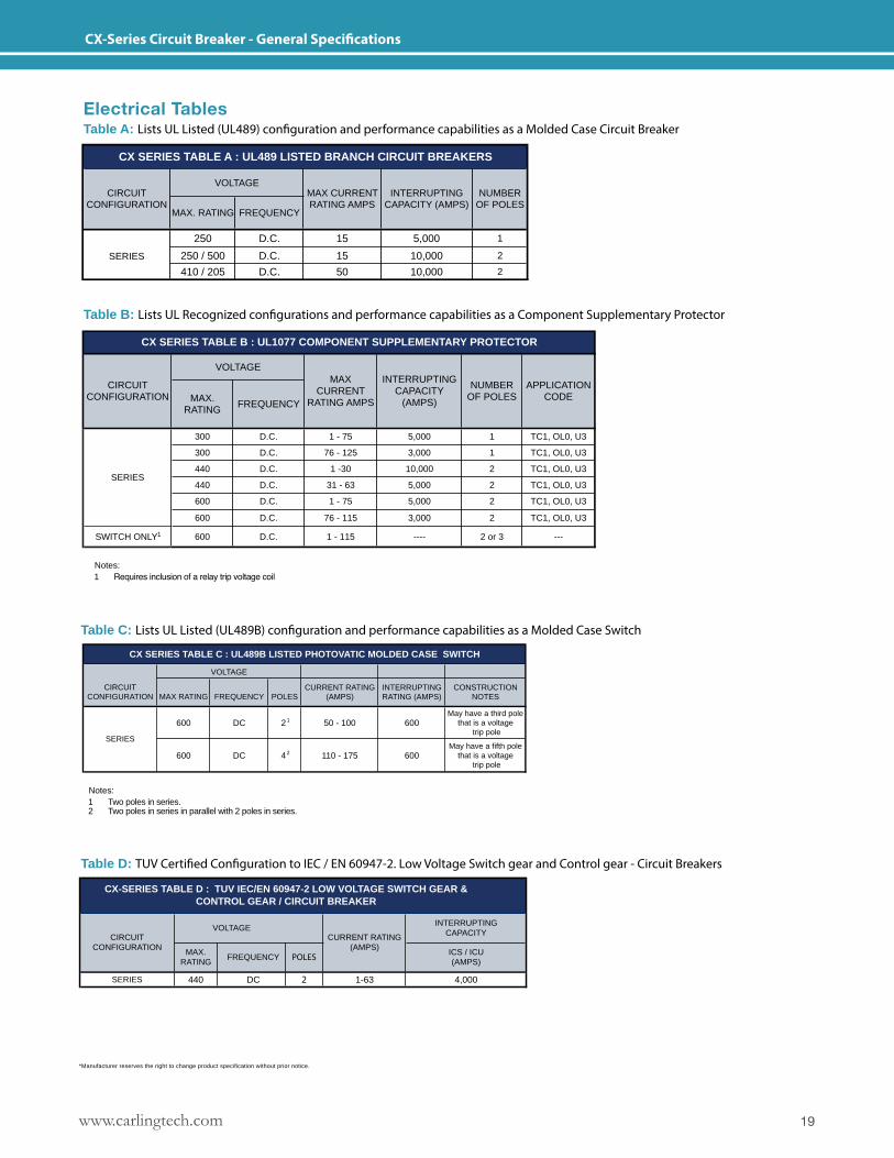
Electrical TablesTable A: Lists UL Listed (UL489) configuration and performance capabilities as a Molded Case Circuit Breaker
Table C: Lists UL Listed (UL489B) configuration and performance capabilities as a Molded Case Switch
Table D: TUV Certified Configuration to IEC / EN 60947-2. Low Voltage Switch gear and Control gear - Circuit Breakers
Table B: Lists UL Recognized configurations and performance capabilities as a Component Supplementary Protector
600 DC 2 1 50 - 100 600May have a third pole
that is a voltage trip pole
600 DC 4 2 110 - 175 600May have a fifth pole
that is a voltage trip pole
SERIES
MAX RATING
CX SERIES TABLE C : UL489B LISTED PHOTOVATIC MOLDED CASE SWITCH
CONSTRUCTION NOTES
VOLTAGE
INTERRUPTING RATING (AMPS)
CURRENT RATING (AMPS)FREQUENCY POLES
CIRCUIT CONFIGURATION
SERIES 440 DC 1-63 4,000
CX-SERIES TABLE D : TUV IEC/EN 60947-2 LOW VOLTAGE SWITCH GEAR & CONTROL GEAR / CIRCUIT BREAKER
VOLTAGE
FREQUENCY
CIRCUIT CONFIGURATION
MAX. RATING
INTERRUPTINGCAPACITY
ICS / ICU(AMPS)
CURRENT RATING(AMPS)
POLES
2
250 D.C. 15 5,000 1
250 / 500 D.C. 15 10,000 2
410 / 205 D.C. 50 10,000 2
SERIES
CX SERIES TABLE A : UL489 LISTED BRANCH CIRCUIT BREAKERS
VOLTAGENUMBER
OF POLESMAX. RATING FREQUENCY
CIRCUIT CONFIGURATION
MAX CURRENT RATING AMPS
INTERRUPTING CAPACITY (AMPS)
300 D.C. 1 - 75 5,000 1 TC1, OL0, U3
300 D.C. 76 - 125 3,000 1 TC1, OL0, U3
440 D.C. 1 -30 10,000 2 TC1, OL0, U3
440 D.C. 31 - 63 5,000 2 TC1, OL0, U3
600 D.C. 1 - 75 5,000 2 TC1, OL0, U3
600 D.C. 76 - 115 3,000 2 TC1, OL0, U3
SWITCH ONLY1 600 D.C. 1 - 115 ---- 2 or 3 ---
SERIES
CX SERIES TABLE B : UL1077 COMPONENT SUPPLEMENTARY PROTECTOR
APPLICATION CODE
VOLTAGE
NUMBER OF POLESMAX.
RATINGFREQUENCY
CIRCUIT CONFIGURATION
MAX CURRENT
RATING AMPS
INTERRUPTING CAPACITY
(AMPS)
Notes: 1 Two poles in series.2 Two poles in series in parallel with 2 poles in series.
Notes: 1 Requires inclusion of a relay trip voltage coil
*Manufacturer reserves the right to change product specification without prior notice.
www.carlingtech.com20
CX-Series Circuit Breaker - General Specifications
OHMS
0.1
1
10
100
1 100100.001
0.01
0.10.01
1000
AMPERE RATING
RESISTANCE, IMPEDANCE VALUESfrom Line to Load Terminals
(Values Based on Series Trip Circuit Breaker) Current(amps)
Tolerance(%)
0.1 -5.0 15%5.1-20.0 25%20.1-125 35%
RESISTANCE PER POLE VALUESfrom Line to Load Terminals
(Values Based on Series Trip Circuit Breaker)
100-125
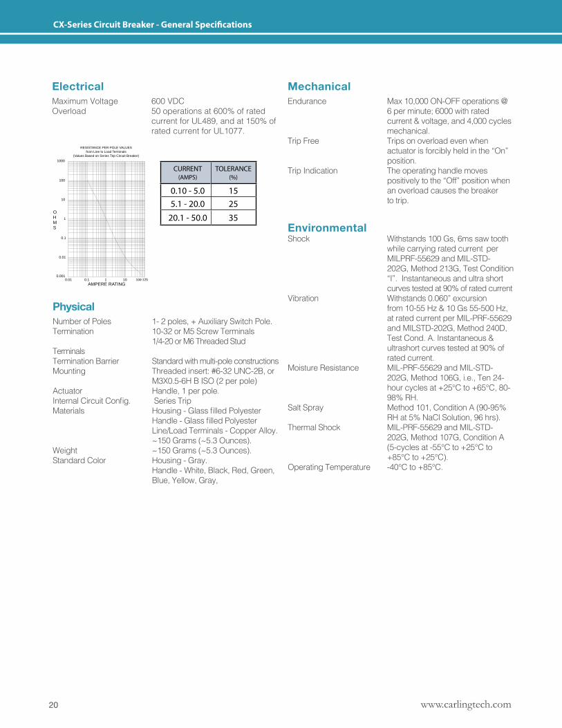
ElectricalMaximum Voltage 600 VDCOverload 50 operations at 600% of rated current for UL489, and at 150% of rated current for UL1077.
MechanicalEndurance Max 10,000 ON-OFF operations @ 6 per minute; 6000 with rated current & voltage, and 4,000 cycles mechanical.Trip Free Trips on overload even when actuator is forcibly held in the “On” position.Trip Indication The operating handle moves positively to the “Off” position when an overload causes the breaker to trip.
EnvironmentalShock Withstands 100 Gs, 6ms saw tooth while carrying rated current per MILPRF-55629 and MIL-STD- 202G, Method 213G, Test Condition “I”. Instantaneous and ultra short curves tested at 90% of rated currentVibration Withstands 0.060” excursion from 10-55 Hz & 10 Gs 55-500 Hz, at rated current per MIL-PRF-55629 and MILSTD-202G, Method 240D, Test Cond. A. Instantaneous & ultrashort curves tested at 90% of rated current.Moisture Resistance MIL-PRF-55629 and MIL-STD- 202G, Method 106G, i.e., Ten 24- hour cycles at +25°C to +65°C, 80- 98% RH.Salt Spray Method 101, Condition A (90-95% RH at 5% NaCl Solution, 96 hrs).Thermal Shock MIL-PRF-55629 and MIL-STD- 202G, Method 107G, Condition A (5-cycles at -55°C to +25°C to +85°C to +25°C).Operating Temperature -40°C to +85°C.
PhysicalNumber of Poles 1- 2 poles, + Auxiliary Switch Pole.Termination 10-32 or M5 Screw Terminals 1/4-20 or M6 Threaded Stud Terminals Termination Barrier Standard with multi-pole constructionsMounting Threaded insert: #6-32 UNC-2B, or M3X0.5-6H B ISO (2 per pole)Actuator Handle, 1 per pole.InternalCircuitConfig. SeriesTripMaterials Housing-GlassfilledPolyester Handle-GlassfilledPolyester Line/Load Terminals - Copper Alloy. ~150 Grams (~5.3 Ounces).Weight ~150 Grams (~5.3 Ounces).Standard Color Housing - Gray. Handle - White, Black, Red, Green, Blue, Yellow, Gray,
CURRENT (AMPS)
TOLERANCE (%)
0.10 - 5.0 155.1 - 20.0 25
20.1 - 50.0 35
21www.carlingtech.com
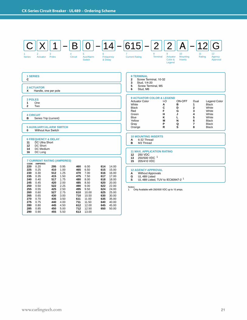
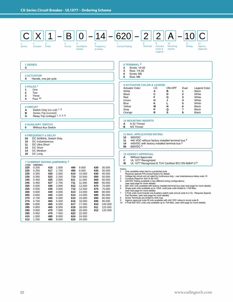
CX-Series Circuit Breaker - UL489 – Ordering Scheme
1Series
2Actuator
3Poles
5Aux/Alarm Switch
6Frequency& Delay
7Current Rating
8Terminal
9ActuatorColor &Legend
10MountingInserts
11Rating
12AgencyApproval
4 Circuit
C X B 2 A1 0 2 12 G14 615
1 SERIESC
2 ACTUATORX Handle, one per pole
8 TERMINAL2 Screw Terminal, 10-323 Stud, 1/4-205 Screw Terminal, M56 Stud, M6
3 POLES 1 One2 Two
4 CIRCUITB Series Trip (current)
5 AUXILIARY/ALARM SWITCH0 Without Aux Switch
6 FREQUENCY & DELAY11 DC Ultra Short12 DC Short14 DC Medium16 DC Long
7 CURRENT RATING (AMPERES)CODE AMPERES220 0.20225 0.25230 0.30235 0.35240 0.40245 0.45250 0.50255 0.55260 0.60265 0.65270 0.70275 0.75280 0.80285 0.85290 0.90
295 0.95410 1.00512 1.25415 1.50517 1.75420 2.00522 2.25425 2.50527 2.75430 3.00435 3.50440 4.00445 4.50450 5.00455 5.50
460 6.00465 6.50470 7.00475 7.50480 8.00485 8.50490 9.00495 9.50610 10.00710 10.50611 11.00711 11.50612 12.00712 12.50613 13.00
614 14.00615 15.00616 16.00617 17.00618 18.00620 20.00622 22.00624 24.00625 25.00630 30.00635 35.00640 40.00645 45.00650 50.00
11 MAX. APPLICATION RATING 12 250 VDC13 250/500 VDC 1
15 205/410 VDC
12 AGENCY APPROVALA Without ApprovalsG UL 489 ListedS UL 489 Listed, TUV to IEC60947-2 1
Notes: 1 Only Available with 250/500 VDC up to 15 amps.
10 MOUNTING INSERTSA 6-32 ThreadB M3 Thread
9 ACTUATOR COLOR & LEGENDActuator Color I-O ON-OFF Dual Legend ColorWhite A B 1 BlackBlack C D 2 WhiteRed F G 3 WhiteGreen H J 4 WhiteBlue K L 5 WhiteYellow M N 6 BlackGray P Q 7 BlackOrange R S 8 Black
www.carlingtech.com22
CX-Series Circuit Breaker - UL1077 – Ordering Scheme
10 MOUNTING INSERTSA 6-32 ThreadB M3 Thread
9 ACTUATOR COLOR & LEGENDActuator Color I-O ON-OFF Dual Legend ColorWhite A B 1 BlackBlack C D 2 WhiteRed F G 3 WhiteGreen H J 4 WhiteBlue K L 5 WhiteYellow M N 6 BlackGray P Q 7 BlackOrange R S 8 Black
1Series
2Actuator
3Poles
5Aux/Alarm Switch
6Frequency& Delay
7Current Rating
8Terminal
12AgencyApproval
4 Circuit
C X B 2 A1 0 2 10 C14 620
1 SERIESC
2 ACTUATORX Handle, one per pole
8 TERMINAL 82 Screw, 10-323 Stud, 1/4-205 Screw, M56 Stud, M6
3 POLES 7 1 One2 Two 3 Three4 Four 10
4 CIRCUITA Switch Only (no coil) 1, 9B Series Trip (current)G Relay Trip (voltage) 1, 2, 3, 9
5 AUXILIARY SWITCH0 Without Aux Switch
6 FREQUENCY & DELAY03 DC 50/60Hz, Switch Only 10 DC Instantaneous11 DC Ultra Short12 DC Short14 DC Medium16 DC Long
7 CURRENT RATING (AMPERES) 6 CODE AMPERES
220 0.200225 0.250230 0.300235 0.350240 0.400245 0.450250 0.500255 0.550260 0.600265 0.650270 0.700275 0.750280 0.800285 0.850290 0.900295 0.950410 1.000512 1.250
415 1.500517 1.750420 2.000522 2.250425 2.500527 2.750430 3.000435 3.500440 4.000445 4.500450 5.000455 5.500460 6.000465 6.500470 7.000475 7.500480 8.000485 8.500
490 9.000495 9.500610 10.000710 10.500611 11.000711 11.500612 12.000712 12.500613 13.000614 14.000615 15.000616 16.000617 17.000618 18.000620 20.000622 22.000624 24.000625 25.000
630 30.000635 35.000640 40.000650 50.000660 60.000665 65.000670 70.000675 75.000680 80.000685 85.000690 90.000695 95.000810 100.000911 115.000912 125.000
11 MAX. APPLICATION RATING 10 300VDC 11 440 VDC without factory installed terminal bus 4
14 440VDC with factory installed terminal bus 4
06 600VDC 5
12 AGENCY APPROVALA Without ApprovalsC UL 1077 RecognizedW UL 1077 Recognized & TUV Certified IEC/ EN 60947-2 9
9ActuatorColor &Legend
10MountingInserts
11Rating
Notes: 1 Only available when tied to a protected pole Requires special P/N consult factory for details2 Voltage trip circuit coil not rated for continuous duty - use instantaneous delay code 103 Contacts Rated for 20A @ 80 VDC4 440VDC Rating available in two different wiring configurations. (see next page for more details)5 600 VDC only available with factory installed terminal bus (see next page for more details)6 Single pole units available up to 125A, multi pole units limited to 115A Max. (see next page for more details)7 3 Pole units must include one Auxiliary switch pole (circuit code A or G) - Requires Special Part Number. (see next page for more details)8 Screw Terminals are limited to 50A max.9 Agency approval code W only available with 440 VDC rating & circuit code B.10 4 Pole 600 VDC units only available up to 75A Max. (see next page for more details)
23www.carlingtech.com
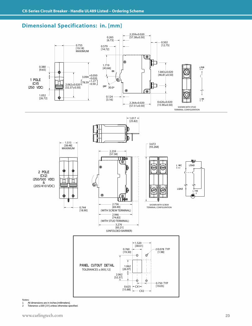
CX-Series Circuit Breaker - Handle UL489 Listed – Ordering Scheme
SHOWN WITH STUDTERMINAL CONFIGURATION
0.755[19.18]MAXIMUM
0.380[9.65]
1.052[26.72]
3.094
78.59
+0.050–0.020+1.27–0.502.062+0.020
[52.37+0.50]
1.719[43.66]
0.124[3.16]
0.579[14.72]
0.265[6.73]
0.502[12.75]
2.259+0.020[57.38+0.50]
1.843+0.020[46.81+0.50]
0.626+0.020[15.90+0.50]
2.264+0.020[57.51+0.50]
30.0º
1.515[38.48]
MAXIMUM
3.672[93.268]
1.017[25.82]
0.744[18.90]
2.259[57.38]
SHOWN WITH SCREWTERMINAL CONFIGURATION
2.736[69.49]
(WITH SCREW TERMINAL)2.946[74.83]
(WITH STUD TERMINAL)3.276[83.21]
0.625[15.88]
(UNFOLDED BARRIER)
TOLERANCES +.005[.12]
CX1CX2
1.520[38.61]
0.760[19.30]
2.062[52.37]
1.062[26.97]
0.750 TYP[19.05]
0.078 TYP[1.98]
&(205/410 VDC)
Notes: 1 All dimensions are in inches [millimeters].2 Tolerance ±.020 [.51] unless otherwise specified.
Dimensional Specifications: in. [mm]
www.carlingtech.com24
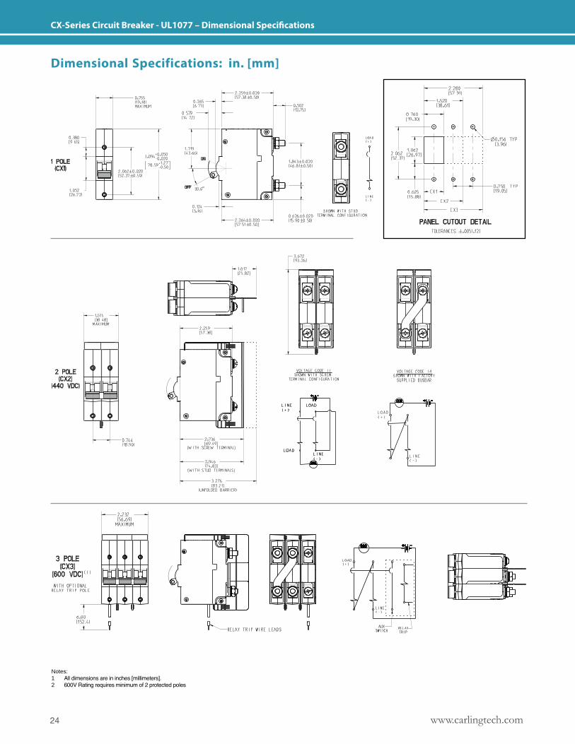
CX-Series Circuit Breaker - UL1077 – Dimensional Specifications
Dimensional Specifications: in. [mm]
Notes: 1 All dimensions are in inches [millimeters].2 600V Rating requires minimum of 2 protected poles
25www.carlingtech.com
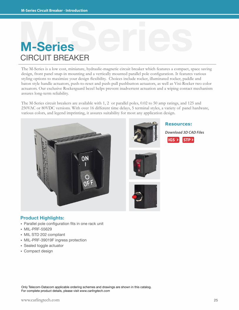
M-Series Circuit Breaker - Introduction
M-SeriesM-SeriesCIRCUIT BREAKERThe M-Series is a low cost, miniature, hydraulic-magnetic circuit breaker which features a compact, space saving design, front panel snap-in mounting and a vertically mounted parallel pole configuration. It features various styling options to maximize your design flexibility. Choices include rocker, illuminated rocker, paddle and baton style handle actuators, push-to-reset and push-pull pushbutton actuators, as well as Visi-Rocker two color actuators. Our exclusive Rockerguard bezel helps prevent inadvertent actuation and a wiping contact mechanism assures long-term reliability. The M-Series circuit breakers are available with 1, 2 or parallel poles, 0.02 to 50 amp ratings, and 125 and 250VAC or 80VDC versions. With over 16 different time delays, 5 terminal styles, a variety of panel hardware, various colors, and legend imprinting, it assures suitability for most any application design.
Product Highlights: � Parallel pole configuration fits in one rack unit � MIL-PRF-55629 � MIL STD 202 compliant � MIL-PRF-39019F ingress protection � Sealed toggle actuator � Compact design
Download 3D CAD Files
Resources:
IGS STP
Only Telecom-Datacom applicable ordering schemes and drawings are shown in this catalog. For complete product details, please visit www.carlingtech.com
www.carlingtech.com26
M-Series Circuit Breaker - General Specifications
*Manufacturer reserves the right to change product specification without prior notice.
Environmental
Physical
MechanicalElectrical
DesignedinaccordancewithrequirementsofspecificationMIL PRF-55629 & MIL-STD-202G as follows:
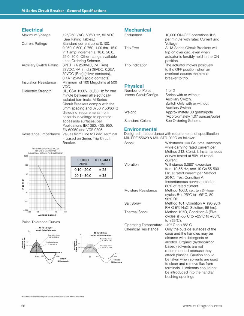
Maximum Voltage 125/250 VAC 50/60 Hz, 80 VDC (See Rating Tables.)Current Ratings Standard current coils: 0.100, 0.250, 0.500, 0.750, 1.00 thru 15.0 in 1 amp increments, 18.0, 20.0, 25.0, 30.0. Other ratings available - see Ordering Scheme.Auxiliary Switch Rating SPDT; 7A 250VAC, 7A (Res) 28VDC, 4A (Ind.) 28VDC, 0.25A 80VDC (Res) (silver contacts), 0.1A 125VAC (gold contacts). Insulation Resistance Minimum of 100 Megohms at 500 VDC.Dielectric Strength UL, CSA 1500V, 50/60 Hz for one minute between all electrically isolated terminals. M-Series Circuit Breakers comply with the 8mm spacing and 3750 V 50/60Hz dielectric requirements from hazardous voltage to operator accessible surfaces, per Publications IEC 380, 435, 950, EN 60950 and VDE 0805. Resistance, Impedance Values from Line to Load Terminal - based on Series Trip Circuit Breaker.
Endurance 10,000 ON-OFF operations @ 6 per minute with rated Current and Voltage.Trip Free All M-Series Circuit Breakers will trip on overload, even when actuator is forcibly held in the ON position.Trip Indication The actuator moves positively to the OFF position when an overload causes the circuit breaker to trip.
Shock Withstands 100 Gs, 6ms, sawtooth while carrying rated current per Method 213, Cond. I. Instantaneous curves tested at 80% of rated current.Vibration Withstands 0.060” excursion from 10-55 Hz, and 10 Gs 55-500 Hz, at rated current per Method 204C, Test Condition A. Instantaneous curves tested at 80% of rated current.Moisture Resistance Method 106D, i.e., ten 24-hour cycles @ + 25°C to +65°C, 80- 98% RH.Salt Spray Method 101, Condition A (90-95% RH @ 5% NaCl Solution, 96 hrs).Thermal Shock Method 107D, Condition A (Five cycles @ -55°C to +25°C to +85°C to +25°C).Operating Temperature -40° C to +85° CChemical Resistance Only the outside surfaces of the case and the handles may be cleaned with detergents or alcohol. Organic (hydrocarbon based) solvents are not recommended because they attack plastics. Caution should be taken when solvents are used tocleanandremovefluxfrom terminals. Lubricants should not be introduced into the handle/ bushing openings
Number of Poles 1 or 2InternalCircuitConfigs. Serieswithorwithout Auxiliary Switch. Switch Only with or without Auxiliary Switch.Weight Approximately 30 grams/pole (Approximately 1.07 ounces/pole)Standard Colors See Ordering Scheme
Pulse Tolerance Curves
RESISTANCE PER POLE VALUESfrom Line to Load Terminals
(Values Based on Series Trip Circuit Breaker)
CURRENT (AMPS)
TOLERANCE (%)
0.10 - 20.0 ± 2520.1 - 50.0 ± 35
27www.carlingtech.com
M-Series Circuit Breaker - General Specifications
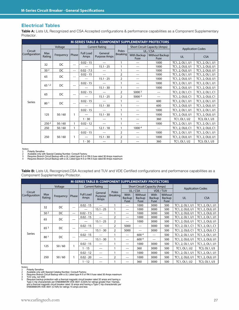
Electrical TablesTable A: ListsULRecognizedandCSAAcceptedconfigurations&performancecapabilitiesasaComponentSupplementaryProtector.
Table B: ListsULRecognized,CSAAcceptedandTUVandVDECertifiedconfigurationsandperformancecapabilitiesasaComponent Supplementary Protector.
Notes: 1 Polarity Sensitive2 Available only with Special Catalog Number. Consult Factory.3 Requires Branch Circuit Backup with a UL Listed type K-5 or RK-5 fuse rated 30 Amps maximum4 TUV only, not VDE5 Requires backup protection with a thermal magnetic circuit breaker rated 32 amps and having a Type C trip characteristic per EN60898/DIN VDE 0641 (C32A) for ratings greater than 15amps, and a thermal magnetic circuit breaker rated 16 amps and having a Type C trip characteristic per EN60898/DIN VDE 0641 (C16A) for ratings 15 amps and less
Notes: 1 Polarity Sensitive2 Available only with Special Catalog Number. Consult Factory.3 Requires Branch Circuit Backup with a UL Listed type K-5 or RK-5 fuse rated 30 Amps maximum4 Requires Branch Circuit Backup with a UL Listed type K-5 or RK-5 fuse rated 60 Amps maximum
M-SERIES TABLE A: COMPONENT SUPPLEMENTARY PROTECTORS
Circuit Configuration
Voltage Current RatingPoles
Breaking
Short Circuit Capacity (Amps)Application Codes
Max Rating Frequency Phase Full Load
AmpsGeneral
Purpose Amps
UL / CSAWith Backup
FuseWithout Backup
Fuse UL CSA
Series
32 DC ---0.02 - 15 --- 1 --- 1000 TC1, 2, OL1, U1 TC1, 2, OL1, U1
--- 15.1 - 25 1 --- 1000 TC1, 2, OL0, U1 TC1, 2, OL0, U150 2 DC --- 0.02 - 7.5 --- 1 --- 1000 TC1, 2, OL0, U1 TC1, 2, OL0, U1
65 DC ---0.02 - 15 --- 2 --- 1000 TC1, 2, OL1, U1 TC1, 2, OL1, U1
--- 15.1 - 25 2 --- 1000 TC1, 2, OL0, U1 TC1, 2, OL0, U1
65 1,2 DC ---0.02 - 15 --- 1 --- 1000 TC1, 2, OL1, U1 TC1, 2, OL1, U1
--- 15.1 - 30 1 --- 1000 TC1, 2, OL0, U1 TC1, 2, OL0, U1
65 DC ---0.02 - 15 --- 2 5000 3 --- TC1, 2, OL1, C1 TC1, 2, OL1, C1
--- 15.1 - 25 2 5000 3 --- TC1, 2, OL0, C1 TC1, 2, OL0, C1
80 1 DC ---0.02 - 15 --- 1 --- 600 TC1, 2, OL1, U1 TC1, 2, OL1, U1
--- 15.1 - 30 1 --- 600 TC1, 2, OL0, U1 TC1, 2, OL0, U1
125 50 / 60 10.02 - 15 --- 1 --- 1000 TC1, 2, OL1, U1 TC1, 2, OL1, U1
--- 15.1 - 30 1 --- 1000 TC1, 2, OL0, U1 TC1, 2, OL0, U11 - 30 --- 1 --- 360 TC1, OL1, U2 TC3, OL1, U3
250 2 50 / 60 1 0.02 - 12 --- 1 --- 1000 TC1, 2, OL1, U1 TC1, 2, OL1, U1250 50 / 60 1 --- 12.1 - 18 1 1000 4 --- TC1, 2, OL0, C1 TC1, 2, OL0, C1
250 50 / 60 10.02 - 15 --- 2 --- 1000 TC1, 2, OL1, U1 TC1, 2, OL1, U1
--- 15.1 - 30 2 --- 1000 TC1, 2, OL0, U1 TC1, 2, OL0, U11 - 30 --- 2 --- 360 TC1, OL1, U2 TC3, OL1, U3
M-SERIES TABLE B: COMPONENT SUPPLEMENTARY PROTECTORS
Circuit Configuration
Voltage Current Rating
Poles Breaking
Short Circuit Capacity (Amps)Application Codes
Max Rating Frequency Phase Full Load
AmpsGeneral Purpose
Amps
UL / CSA VDE / TUVWith
Backup Fuse
Without Backup
Fuse
With Backup
Fuse
Without Backup
FuseUL CSA
Series
32 DC ---0.02 - 15 --- 1 --- 1000 3000 500 TC1, 2, OL1, U1 TC1, 2, OL1, U1
--- 15.1 - 25 1 --- 1000 3000 500 TC1, 2, OL0, U1 TC1, 2, OL0, U150 2 DC --- 0.02 - 7.5 --- 1 --- 1000 3000 500 TC1, 2, OL0, U1 TC1, 2, OL0, U1
65 DC ---0.02 - 15 --- 2 --- 1000 3000 500 TC1, 2, OL1, U1 TC1, 2, OL1, U1
--- 15.1 - 25 2 --- 1000 3000 500 TC1, 2, OL0, U1 TC1, 2, OL0, U1
65 3 DC ---0.02 - 15 --- 2 5000 --- 3000 500 TC1, 2, OL1, C1 TC1, 2, OL1, C1
--- 15.1 - 30 2 5000 --- 3000 500 TC1, 2, OL0, C1 TC1, 2, OL0, C1
80 1 DC ---0.02 - 15 --- 1 --- 600 4 --- 500 TC1, 2, OL1, U1 TC1, 2, OL1, U1
--- 15.1 - 30 1 --- 600 4 --- 500 TC1, 2, OL0, U1 TC1, 2, OL0, U1
125 50 / 60 10.02 - 15 --- 1 --- 1000 3000 500 TC1, 2, OL1, U1 TC1, 2, OL1, U1
1 - 15 --- 1 --- 360 3000 500 TC1, OL1, U2 TC3, OL1, U3
250 50 / 60 10.02 - 12 --- 1 --- 1000 3000 500 TC1, 2, OL1, U1 TC1, 2, OL1, U10.02 - 20 --- 2 --- 1000 3000 500 TC1, 2, OL0, U1 TC1, 2, OL0, U1
1 - 12 --- 1 --- 360 3000 500 TC1, OL1, U2 TC3, OL1, U3
www.carlingtech.com28
M-Series Circuit Breaker - General Specifications
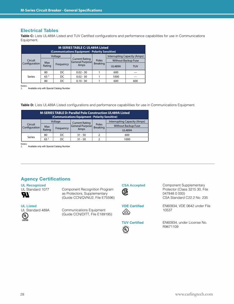
Electrical TablesTable C: ListsUL489AListedandTUVCertifiedconfigurationsandperformancecapabilitiesforuseinCommunicationsEquipment.
Table D: ListsUL489AListedconfigurationsandperformancecapabilitiesforuseinCommunicationsEquipment.
Notes:1. Available only with Special Catalog Number
Notes:1. Available only with Special Catalog Number
Agency CertificationsUL RecognizedUL Standard 1077
UL ListedUL Standard 489A
CSA Accepted
VDE Certified
TUV Certified
Component Recognition Program as Protectors, Supplementary (Guide CCN/QVNU2, File E75596)
Communications Equipment (Guide CCN/DITT, File E189195)
Component Supplementary Protector (Class 3215 30, File 047848 0 000)CSA Standard C22.2 No. 235
EN60934, VDE 0642 under File 10537
EN60934, under License No. R9671109
M-SERIES TABLE C: UL489A Listed (Communications Equipment - Polarity Sensitive)
Circuit Configuration
VoltageCurrent Rating
General Purpose Amps
Poles Breaking
Interrupting Capacity (Amps)
Max Rating Frequency
Without Backup Fuse
UL489A TUV
Series80 DC 0.02 - 30 1 600 ---65 1 DC 0.02 - 30 1 1000 ---80 DC 0.10 - 30 1 600 600
M-SERIES TABLE D: Parallel Pole Construction UL489A Listed (Communications Equipment - Polarity Sensitive)
Circuit Configuration
Voltage Current Rating General Purpose
AmpsPoles
Breaking
Interrupting Capacity (Amps)
Max Rating Frequency
Without Backup FuseUL489A
Series80 DC 31 - 50 2 60065 1 DC 31 - 50 2 1000
29www.carlingtech.com
M-Series Circuit Breaker - Parallel Pole Rocker - Ordering Scheme
1Series
2Actuator
3Poles
6Current Rating
7Terminal
8Illumination
12AgencyApproval
4 Circuit
5 Frequency & Delay
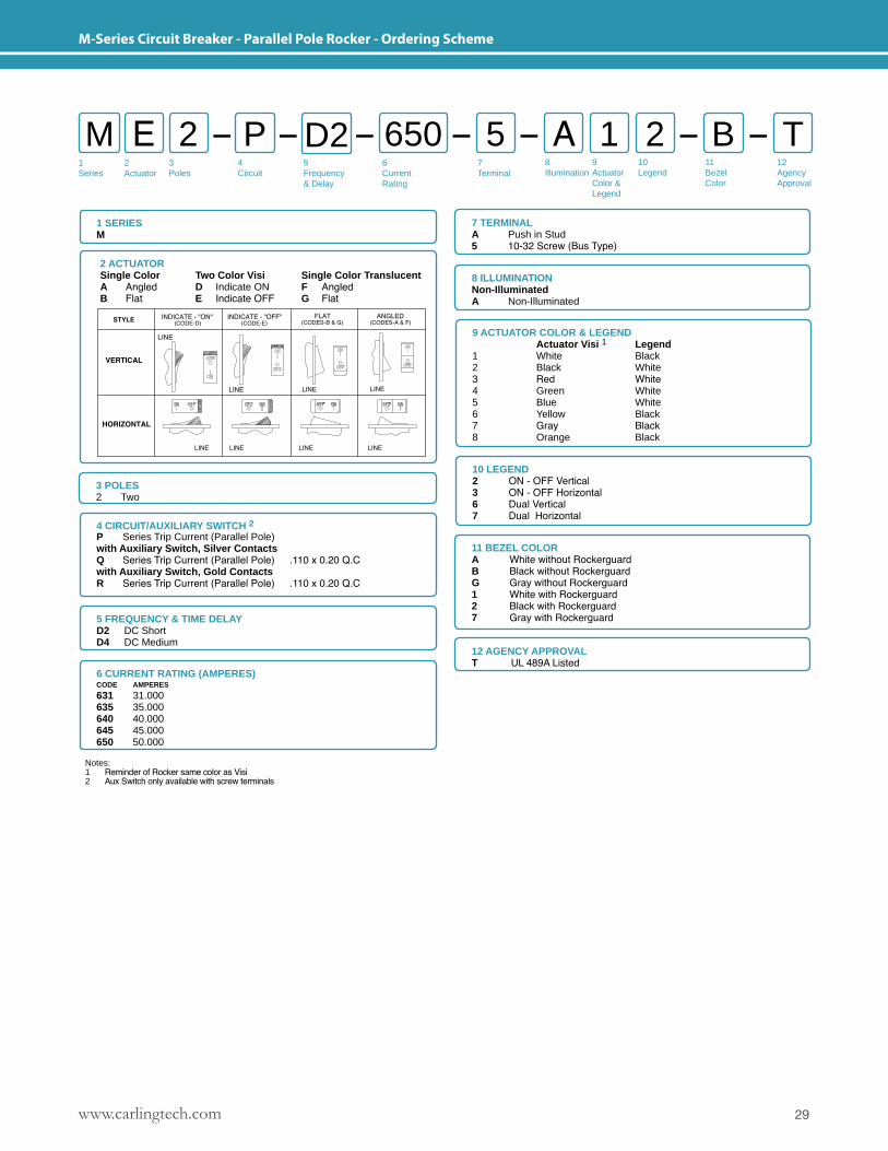
M E P A5 22 1 TBD2 650
1 SERIESM
7 TERMINALA Push in Stud5 10-32 Screw (Bus Type)
3 POLES 2 Two
4 CIRCUIT/AUXILIARY SWITCH 2P Series Trip Current (Parallel Pole)with Auxiliary Switch, Silver ContactsQ Series Trip Current (Parallel Pole) .110 x 0.20 Q.Cwith Auxiliary Switch, Gold ContactsR Series Trip Current (Parallel Pole) .110 x 0.20 Q.C
5 FREQUENCY & TIME DELAYD2 DC Short D4 DC Medium
12 AGENCY APPROVALT UL 489A Listed
11 BEZEL COLORA White without RockerguardB Black without RockerguardG Gray without Rockerguard1 White with Rockerguard2 Black with Rockerguard7 Gray with Rockerguard
9Actuator Color & Legend
10Legend
11Bezel Color
8 ILLUMINATIONNon-IlluminatedA Non-Illuminated
9 ACTUATOR COLOR & LEGEND Actuator Visi 1 Legend1 White Black2 Black White3 Red White4 Green White5 Blue White6 Yellow Black7 Gray Black8 Orange Black
10 LEGEND2 ON - OFF Vertical 3 ON - OFF Horizontal6 Dual Vertical 7 Dual Horizontal
2 ACTUATORSingle Color Two Color Visi Single Color TranslucentA Angled D Indicate ON F AngledB Flat E Indicate OFF G Flat
Notes: 1 Reminder of Rocker same color as Visi2 Aux Switch only available with screw terminals
6 CURRENT RATING (AMPERES) CODE AMPERES
631 31.000635 35.000640 40.000645 45.000650 50.000
www.carlingtech.com30
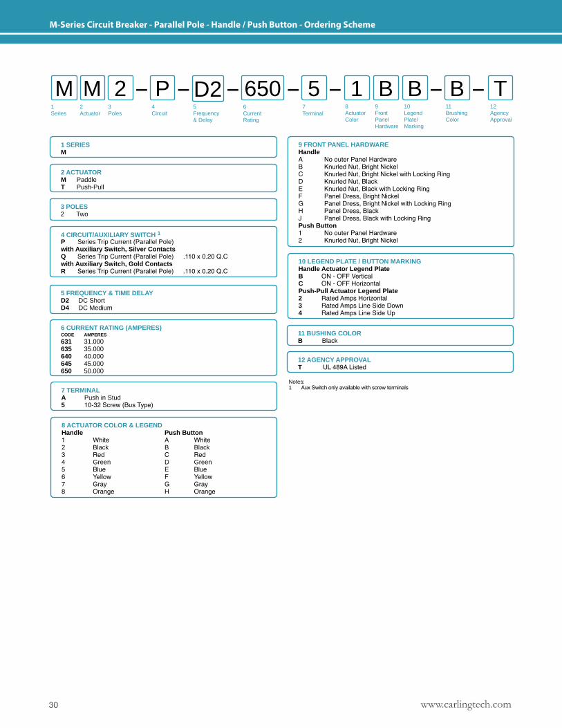
M-Series Circuit Breaker - Parallel Pole - Handle / Push Button - Ordering Scheme
6 CURRENT RATING (AMPERES) CODE AMPERES
631 31.000635 35.000640 40.000645 45.000650 50.000
1 SERIESM
7 TERMINALA Push in Stud5 10-32 Screw (Bus Type)
3 POLES 2 Two
4 CIRCUIT/AUXILIARY SWITCH 1P Series Trip Current (Parallel Pole)with Auxiliary Switch, Silver ContactsQ Series Trip Current (Parallel Pole) .110 x 0.20 Q.Cwith Auxiliary Switch, Gold ContactsR Series Trip Current (Parallel Pole) .110 x 0.20 Q.C
5 FREQUENCY & TIME DELAYD2 DC Short D4 DC Medium
12 AGENCY APPROVALT UL 489A Listed
11 BUSHING COLORB Black
9 FRONT PANEL HARDWAREHandleA No outer Panel HardwareB Knurled Nut, Bright NickelC Knurled Nut, Bright Nickel with Locking RingD Knurled Nut, BlackE Knurled Nut, Black with Locking RingF Panel Dress, Bright NickelG Panel Dress, Bright Nickel with Locking RingH Panel Dress, BlackJ Panel Dress, Black with Locking RingPush Button1 No outer Panel Hardware2 Knurled Nut, Bright Nickel
10 LEGEND PLATE / BUTTON MARKINGHandle Actuator Legend PlateB ON - OFF Vertical C ON - OFF HorizontalPush-Pull Actuator Legend Plate2 Rated Amps Horizontal 3 Rated Amps Line Side Down4 Rated Amps Line Side Up
2 ACTUATORM PaddleT Push-Pull
8 ACTUATOR COLOR & LEGENDHandle Push Button1 White A White2 Black B Black3 Red C Red4 Green D Green5 Blue E Blue6 Yellow F Yellow7 Gray G Gray8 Orange H Orange
Notes: 1 Aux Switch only available with screw terminals
1Series
2Actuator
3Poles
6Current Rating
7Terminal
8Actuator Color
12AgencyApproval
4 Circuit
5 Frequency & Delay
M M P 15 B2 B TBD2 6509Front Panel Hardware
10Legend Plate/ Marking
11BrushingColor
31www.carlingtech.com
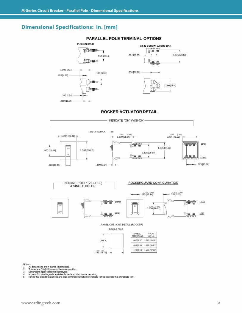
M-Series Circuit Breaker - Parallel Pole - Dimensional Specifications
1.304 [33.12]
1.125 [28.58]
.970 [24.64]1.375 [34.93]
1.125 [28.58]1.560 [39.62]
.370 [9.40] MAX.
INDICATE "OFF" (VISI-OFF)& SINGLE COLOR
ON
OFF
.400 [10.16]
ON
OFF
±.020 ±.5081.050 [26.67]
ON
PANEL CUT - OUT DETAIL (ROCKER)
.125 [3.18]
PANELTHICKNESS
.093 [2.36]
.062 [1.57]
OFF
1.139 [33.76]
DOUBLE POLE
DIM. A
±.005 ±.13
LINE
DIM. A
1.460 [37.08]
+.005 +.13-.000 -.00
1.420 [36.07]
1.385 [35.18]
ROCKERGUARD CONFIGURATION
.675 [17.14]
.100 [2.54]
LOAD
±.020 ±.508.305 [7.75]
±.020 ±.508
PUSH-IN STUD
1.000 [25.4]
.750 [19.05]
.100 [2.54]
1.394 [35.41]
.393 [9.97]
1.000 [25.4]
.154 [3.91]
ROCKER ACTUATOR DETAIL
1.530 [38.86]
INDICATE "ON" (VISI-ON)
±.020 [±.508] ±.020 [±.508]
.652 [16.56]
.838 [21.29]
PARALLEL POLE TERMINAL OPTIONS
.912 [23.16]
10-32 SCREW W/ BUS BAR
M SERIES PARALLEL POLEFORM & FIT DIAGRAMS
NOTES:1. ALL DIMENSIONS ARE IN INCHES [MILLIMETERS].2. TOLERANCE ±.010 [.25] UNLESS OTHERWISE SPECIFIED.3. DIMENSIONS APPLY TO BOTH ROCKER STYLES.4. I-O, ON-OFF OR DUAL LEGENDS AVAILABLE FOR
VERTICAL OR HORIZONTAL MOUNTING.5. NOTICE THAT CIRCUIT BREAKER LINE AND LOAD TERMINAL
ORIENTATION ON INDICATE "OFF" IS OPPOSITE THAT OFINDICATE "ON".
ME5/10/12
LINE
DR BY
TITLE
.625 [15.88]
LOAD
LOAD
DWG NO
SHT OF
CLA-8121APVD BY
1 3
REV
A
LINE
REVISIONS
RELEASED PERECO 16976
LET
A
DATE
5-10-12
Dimensional Specifications: in. [mm]
Notes: 1 All dimensions are in inches [millimeters].2 Tolerance ±.010 [.25] unless otherwise specified.3 Dimensions apply to both rocker styles.4 I-o, on-off or dual legends available for vertical or horizontal mounting.5 Notice that circuit breaker line and load terminal orientation on indicate “off” is opposite that of indicate “on”.
www.carlingtech.com32
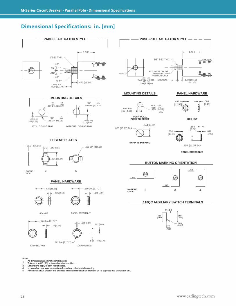
M-Series Circuit Breaker - Parallel Pole - Dimensional Specifications
.105 [2.67]
.125 [3.18]
HEX NUT
.625 [15.88]
KNURLED NUT
.683 DIA [Ø17.27]
PANEL DRESS NUT
LEGEND PLATES
.680 DIA [Ø17.27]
.632 DIA [Ø16.05]
.680 DIA [Ø17.27]
.180 [4.57]
.340 [8.64]
B
0N
0FF
.025 [.64]
LEGENDCODE:
PANEL HARDWARE
1.025 [26.04] ON
C
OFF
.125 [3.18]
.470 [11.94]FLAT
.500 [12.70]
.222 [5.64]
.500 DIA [Ø12.70]
WITHOUT LOCKING RING
±.002 [±.050].125 DIA [Ø3.18]
.500 DIA [Ø12.70]
WITH LOCKING RING
.355 [9.02]±.005 [±.13]
+.010-.000
+.25-.000
+.010-.000
MOUNTING DETAILS+.25-.000
±.030 ±.76
+.25-.000
+.010-.000
PADDLE ACTUATOR STYLE
1.395
12°
1/2-32 THD.
12°
ON
OFF
M SERIES PARALLEL POLEFORM & FIT DIAGRAMS
NOTES:1. ALL DIMENSIONS ARE IN INCHES [MILLIMETERS].2. TOLERANCE ±.010 [.25] UNLESS OTHERWISE SPECIFIED.3. DIMENSIONS APPLY TO BOTH ROCKER STYLES.4. I-O, ON-OFF OR DUAL LEGENDS AVAILABLE FOR
VERTICAL OR HORIZONTAL MOUNTING.5. NOTICE THAT CIRCUIT BREAKER LINE AND LOAD TERMINAL
ORIENTATION ON INDICATE "OFF" IS OPPOSITE THAT OFINDICATE "ON".
ME5/10/12
.031 [.79]
LOCKING RING
DR BY
TITLE
.342 [8.69]
2 3
APVD BY DWG NO
SHT OF
CLA-8121REV
A
REVISIONS
RELEASED PERECO 16976
LET
A
DATE
5-10-12
.435 [11.05] DIA
PANEL DRESS NUT
PANEL HARDWARE
HEX NUT
.156[3.56]
.534[13.56]
20 20
2
LINE
MARKINGCODE:
20
BUTTON MARKING ORIENTATION
.110QC AUXILIARY SWITCH TERMINALS
LINE
3 4
LINE
SNAP-IN BUSHING
.162 [4.11]
.625 [15.87] DIA
MOUNTING DETAILS
.500 [12.70] OFF (SHOWN) .400 [10.16]
±.002 ±.05
.280 [7.11] ON±.030 ±.76
PUSH-PULL,PUSH TO RESET
.375 [9.53]DIA
.544[13.82]
.494[12.55]
±.030 ±.76
PUSH-PULL ACTUATOR STYLE
±.030 ±.76
FLAT
1.484
3/8" 8-32 THD.
ACTUATOR COLORVISIBLE IN OFF
POSITION ONLY
NOTES:1. ALL DIMENSIONS ARE IN INCHES [MILLIMETERS].2. TOLERANCE ±.010 [.25] UNLESS OTHERWISE SPECIFIED.3. DIMENSIONS APPLY TO BOTH ROCKER STYLES.4. I-O, ON-OFF OR DUAL LEGENDS AVAILABLE FOR
VERTICAL OR HORIZONTAL MOUNTING.5. NOTICE THAT CIRCUIT BREAKER LINE AND LOAD TERMINAL
ORIENTATION ON INDICATE "OFF" IS OPPOSITE THAT OFINDICATE "ON".
ME5/10/12
DR BY
TITLE
3 3
M SERIES PARALLEL POLEFORM & FIT DIAGRAMS
APVD BY DWG NO
SHT OF
CLA-8121REV
A
.098[2.49]
.078[1.98]
REVISIONS
RELEASED PERECO 16976
LET
A
DATE
5-10-12
+.010 -.000
+.25 -.00
Dimensional Specifications: in. [mm]
Notes: 1 All dimensions are in inches [millimeters].2 Tolerance ±.010 [.25] unless otherwise specified.3 Dimensions apply to both rocker styles.4 I-o, on-off or dual legends available for vertical or horizontal mounting.5 Notice that circuit breaker line and load terminal orientation on indicate “off” is opposite that of indicate “on”.
33www.carlingtech.com
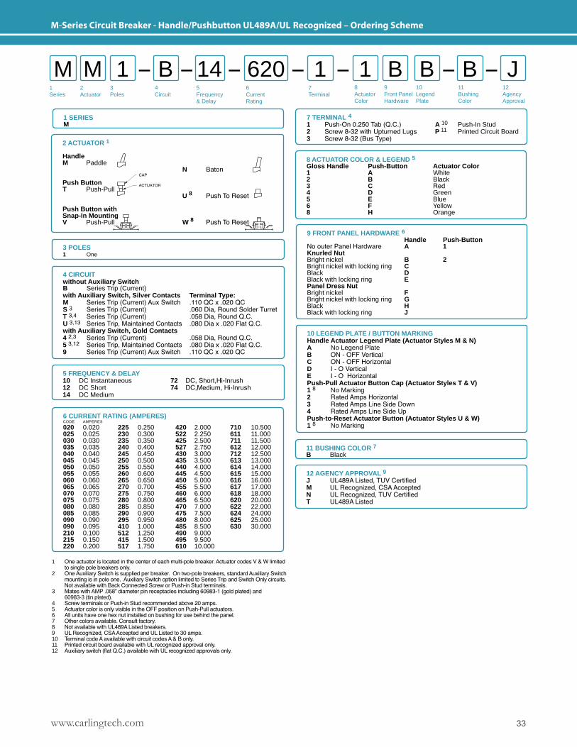
M-Series Circuit Breaker - Handle/Pushbutton UL489A/UL Recognized – Ordering Scheme
3 POLES 1 One
4 CIRCUITwithout Auxiliary SwitchB Series Trip (Current)with Auxiliary Switch, Silver Contacts Terminal Type:M Series Trip (Current) Aux Switch .110 QC x .020 QCS 3 Series Trip (Current) .060 Dia, Round Solder TurretT 3,4 Series Trip (Current) .058 Dia, Round Q.C.U 3,13 Series Trip, Maintained Contacts .080 Dia x .020 Flat Q.C.with Auxiliary Switch, Gold Contacts 4 2,3 Series Trip (Current) .058 Dia, Round Q.C.5 3,12 Series Trip, Maintained Contacts .080 Dia x .020 Flat Q.C.9 Series Trip (Current) Aux Switch .110 QC x .020 QC
9 FRONT PANEL HARDWARE 6 Handle Push-ButtonNo outer Panel Hardware A 1Knurled NutBright nickel B 2Bright nickel with locking ring CBlack DBlack with locking ring EPanel Dress Nut Bright nickel FBright nickel with locking ring GBlack HBlack with locking ring J
10 LEGEND PLATE / BUTTON MARKINGHandle Actuator Legend Plate (Actuator Styles M & N)A No Legend Plate B ON - OFF Vertical C ON - OFF HorizontalD I - O Vertical E I - O HorizontalPush-Pull Actuator Button Cap (Actuator Styles T & V)1 8 No Marking2 Rated Amps Horizontal3 Rated Amps Line Side Down4 Rated Amps Line Side UpPush-to-Reset Actuator Button (Actuator Styles U & W)1 8 No Marking
2 ACTUATOR 1
HandleM Paddle
Push ButtonT Push-Pull
Push Button with Snap-In MountingV Push-Pull
N Baton
U 8 Push To Reset
W 8 Push To Reset
1 One actuator is located in the center of each multi-pole breaker. Actuator codes V & W limited to single pole breakers only.2 One Auxiliary Switch is supplied per breaker. On two-pole breakers, standard Auxiliary Switch mounting is in pole one. Auxiliary Switch option limited to Series Trip and Switch Only circuits. Not available with Back Connected Screw or Push-in Stud terminals.3 Mates with AMP .058” diameter pin receptacles including 60983-1 (gold plated) and 60983-3 (tin plated).4 Screw terminals or Push-in Stud recommended above 20 amps.5 Actuator color is only visible in the OFF position on Push-Pull actuators. 6 All units have one hex nut installed on bushing for use behind the panel. 7 Other colors available. Consult factory.8 Not available with UL489A Listed breakers.9 UL Recognized, CSA Accepted and UL Listed to 30 amps.10 Terminal code A available with circuit codes A & B only.11 Printed circuit board available with UL recognized approval only.12 Auxiliary switch (flat Q.C.) available with UL recognized approvals only.
8 ACTUATOR COLOR & LEGEND 5Gloss Handle Push-Button Actuator Color1 A White2 B Black3 C Red4 D Green5 E Blue6 F Yellow8 H Orange
1 SERIESM
12 AGENCY APPROVAL 9J UL489A Listed, TUV CertifiedM UL Recognized, CSA AcceptedN UL Recognized, TUV CertifiedT UL489A Listed
11 BUSHING COLOR 7B Black
5 FREQUENCY & DELAY10 DC Instantaneous 72 DC, Short,Hi-Inrush12 DC Short 74 DC,Medium, Hi-Inrush14 DC Medium
7 TERMINAL 41 Push-On 0.250 Tab (Q.C.) A 10 Push-In Stud2 Screw 8-32 with Upturned Lugs P 11 Printed Circuit Board3 Screw 8-32 (Bus Type)
6 CURRENT RATING (AMPERES)CODE AMPERES
020 0.020 225 0.250 420 2.000 710 10.500025 0.025 230 0.300 522 2.250 611 11.000030 0.030 235 0.350 425 2.500 711 11.500035 0.035 240 0.400 527 2.750 612 12.000040 0.040 245 0.450 430 3.000 712 12.500045 0.045 250 0.500 435 3.500 613 13.000050 0.050 255 0.550 440 4.000 614 14.000055 0.055 260 0.600 445 4.500 615 15.000060 0.060 265 0.650 450 5.000 616 16.000065 0.065 270 0.700 455 5.500 617 17.000070 0.070 275 0.750 460 6.000 618 18.000075 0.075 280 0.800 465 6.500 620 20.000080 0.080 285 0.850 470 7.000 622 22.000085 0.085 290 0.900 475 7.500 624 24.000090 0.090 295 0.950 480 8.000 625 25.000090 0.095 410 1.000 485 8.500 630 30.000210 0.100 512 1.250 490 9.000 215 0.150 415 1.500 495 9.500 220 0.200 517 1.750 610 10.000
1Series
2Actuator
3Poles
6Current Rating
7Terminal
8Actuator Color
12AgencyApproval
4 Circuit
5 Frequency & Delay
M M B 11 B1 B JB14 6209Front Panel Hardware
10Legend Plate
11Bushing Color
www.carlingtech.com34
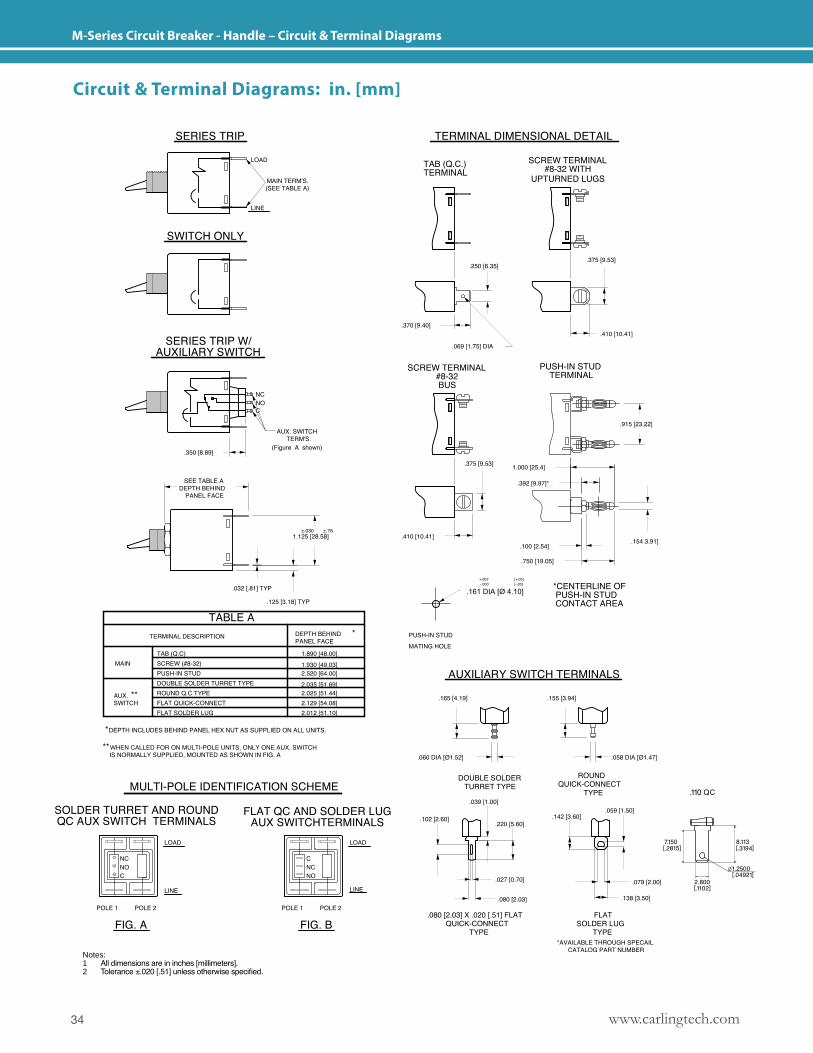
M-Series Circuit Breaker - Handle – Circuit & Terminal Diagrams
Notes: 1 All dimensions are in inches [millimeters].2 Tolerance ±.020 [.51] unless otherwise specified.
Circuit & Terminal Diagrams: in. [mm]
35www.carlingtech.com
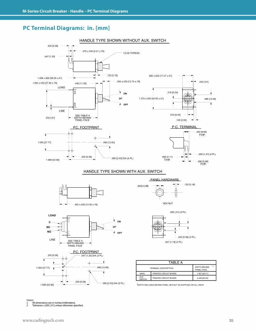
M-Series Circuit Breaker - Handle – PC Terminal Diagrams
Notes: 1 All dimensions are in inches [millimeters].2 Tolerance ±.020 [.51] unless otherwise specified.
PC Terminal Diagrams: in. [mm]
www.carlingtech.com36
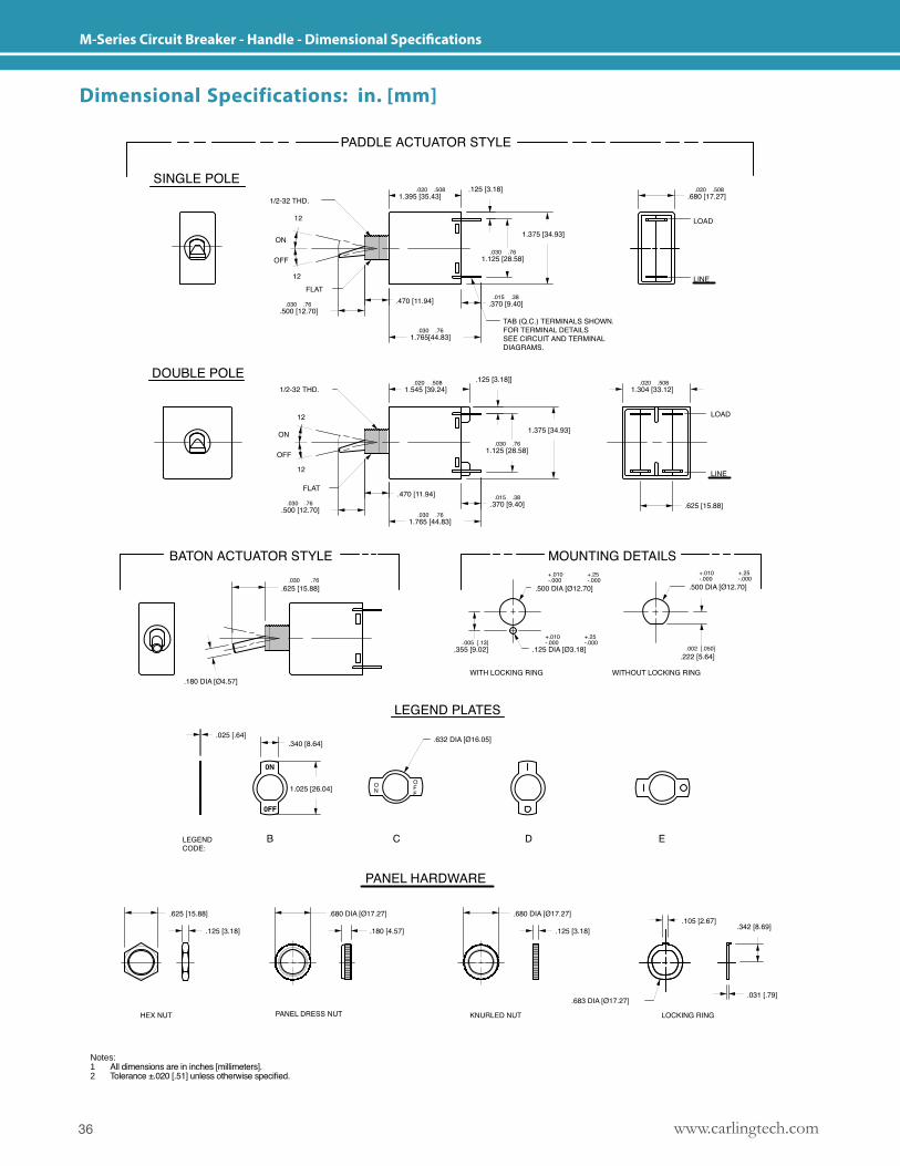
M-Series Circuit Breaker - Handle - Dimensional Specifications
Dimensional Specifications: in. [mm]
Notes: 1 All dimensions are in inches [millimeters].2 Tolerance ±.020 [.51] unless otherwise specified.
37www.carlingtech.com
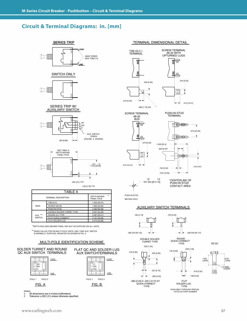
M-Series Circuit Breaker - Pushbutton – Circuit & Terminal Diagrams
Circuit & Terminal Diagrams: in. [mm]
Notes: 1 All dimensions are in inches [millimeters].2 Tolerance ±.020 [.51] unless otherwise specified.
www.carlingtech.com38
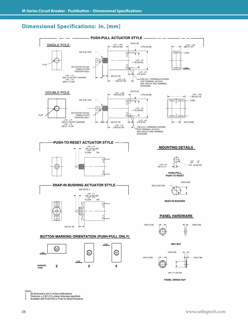
M-Series Circuit Breaker - Pushbutton – Dimensional Specifications
Dimensional Specifications: in. [mm]
Notes: 1 All dimensions are in inches [millimeters].2 Tolerance ± 0.20 [.51] unless otherwise specified.3 Available with Push-Pull or Push-to-Reset Actuators
39www.carlingtech.com
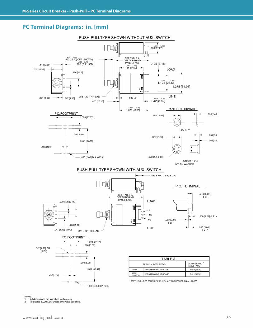
M-Series Circuit Breaker - Push-Pull – PC Terminal Diagrams
PC Terminal Diagrams: in. [mm]
Notes: 1 All dimensions are in inches [millimeters].2 Tolerance ±.020 [.51] unless otherwise specified.
www.carlingtech.com40
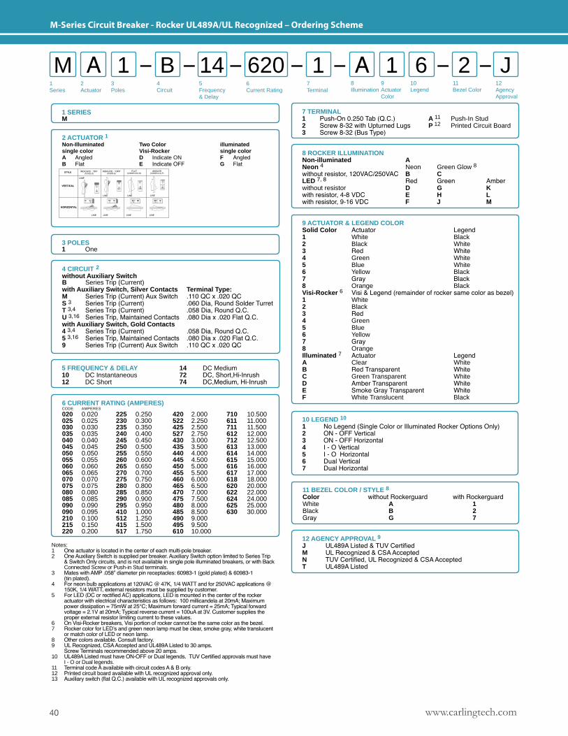
M-Series Circuit Breaker - Rocker UL489A/UL Recognized – Ordering Scheme
8 ROCKER ILLUMINATIONNon-illuminated ANeon 4 Neon Green Glow 8without resistor, 120VAC/250VAC B CLED 7, 8 Red Green Amberwithout resistor D G Kwith resistor, 4-8 VDC E H Lwith resistor, 9-16 VDC F J M
9 ACTUATOR & LEGEND COLORSolid Color Actuator Legend1 White Black2 Black White3 Red White4 Green White5 Blue White6 Yellow Black7 Gray Black8 Orange BlackVisi-Rocker 6 Visi & Legend (remainder of rocker same color as bezel)1 White2 Black3 Red4 Green5 Blue6 Yellow7 Gray8 OrangeIlluminated 7 Actuator LegendA Clear WhiteB Red Transparent WhiteC Green Transparent WhiteD Amber Transparent WhiteE Smoke Gray Transparent WhiteF White Translucent Black
2 ACTUATOR 1Non-Illuminated Two Color illuminated single color Visi-Rocker single color A Angled D Indicate ON F AngledB Flat E Indicate OFF G Flat
11 BEZEL COLOR / STYLE 8Color without Rockerguard with RockerguardWhite A 1Black B 2Gray G 7
1 SERIESM
3 POLES 1 One
5 FREQUENCY & DELAY10 DC Instantaneous12 DC Short
14 DC Medium72 DC, Short,Hi-Inrush 74 DC,Medium, Hi-Inrush
10 LEGEND 10
1 No Legend (Single Color or Illuminated Rocker Options Only)2 ON - OFF Vertical 3 ON - OFF Horizontal4 I - O Vertical 5 I - O Horizontal6 Dual Vertical 7 Dual Horizontal
12 AGENCY APPROVAL 9
J UL489A Listed & TUV CertifiedM UL Recognized & CSA AcceptedN TUV Certified, UL Recognized & CSA AcceptedT UL489A Listed
6 CURRENT RATING (AMPERES)CODE AMPERES
020 0.020 225 0.250 420 2.000 710 10.500025 0.025 230 0.300 522 2.250 611 11.000030 0.030 235 0.350 425 2.500 711 11.500035 0.035 240 0.400 527 2.750 612 12.000040 0.040 245 0.450 430 3.000 712 12.500045 0.045 250 0.500 435 3.500 613 13.000050 0.050 255 0.550 440 4.000 614 14.000055 0.055 260 0.600 445 4.500 615 15.000060 0.060 265 0.650 450 5.000 616 16.000065 0.065 270 0.700 455 5.500 617 17.000070 0.070 275 0.750 460 6.000 618 18.000075 0.075 280 0.800 465 6.500 620 20.000080 0.080 285 0.850 470 7.000 622 22.000085 0.085 290 0.900 475 7.500 624 24.000090 0.090 295 0.950 480 8.000 625 25.000090 0.095 410 1.000 485 8.500 630 30.000210 0.100 512 1.250 490 9.000 215 0.150 415 1.500 495 9.500 220 0.200 517 1.750 610 10.000
4 CIRCUIT 2without Auxiliary SwitchB Series Trip (Current)with Auxiliary Switch, Silver Contacts Terminal Type:M Series Trip (Current) Aux Switch .110 QC x .020 QCS 3 Series Trip (Current) .060 Dia, Round Solder TurretT 3,4 Series Trip (Current) .058 Dia, Round Q.C.U 3,16 Series Trip, Maintained Contacts .080 Dia x .020 Flat Q.C.with Auxiliary Switch, Gold Contacts 4 3,4 Series Trip (Current) .058 Dia, Round Q.C.5 3,16 Series Trip, Maintained Contacts .080 Dia x .020 Flat Q.C.9 Series Trip (Current) Aux Switch .110 QC x .020 QC
Notes:1 One actuator is located in the center of each multi-pole breaker.2 One Auxiliary Switch is supplied per breaker. Auxiliary Switch option limited to Series Trip & Switch Only circuits, and is not available in single pole illuminated breakers, or with Back Connected Screw or Push-in Stud terminals.3 Mates with AMP .058” diameter pin receptacles: 60983-1 (gold plated) & 60983-1 (tin plated).4 For neon bulb applications at 120VAC @ 47K, 1/4 WATT and for 250VAC applications @ 150K, 1/4 WATT, external resistors must be supplied by customer.5 For LED (DC or rectified AC) applications, LED is mounted in the center of the rocker actuator with electrical characteristics as follows: 100 millicandela at 20mA; Maximum power dissipation = 75mW at 25°C; Maximum forward current = 25mA; Typical forward voltage = 2.1V at 20mA; Typical reverse current = 100uA at 3V. Customer supplies the proper external resistor limiting current to these values.6 On Visi-Rocker breakers, Visi portion of rocker cannot be the same color as the bezel. 7 Rocker color for LED’s and green neon lamp must be clear, smoke gray, white translucent or match color of LED or neon lamp.8 Other colors available. Consult factory.9 UL Recognized, CSA Accepted and UL489A Listed to 30 amps. Screw Terminals recommended above 20 amps.10 UL489A Listed must have ON-OFF or Dual legends. TUV Certified approvals must have I - O or Dual legends.11 Terminal code A available with circuit codes A & B only.12 Printed circuit board available with UL recognized approval only.13 Auxiliary switch (flat Q.C.) available with UL recognized approvals only.
7 TERMINAL1 Push-On 0.250 Tab (Q.C.) A 11 Push-In Stud2 Screw 8-32 with Upturned Lugs P 12 Printed Circuit Board3 Screw 8-32 (Bus Type)
1Series
2Actuator
3Poles
6Current Rating
7Terminal
8Illumination
12AgencyApproval
4 Circuit
5 Frequency & Delay
M A B A1 61 1 J214 6209Actuator Color
10Legend
11Bezel Color
41www.carlingtech.com
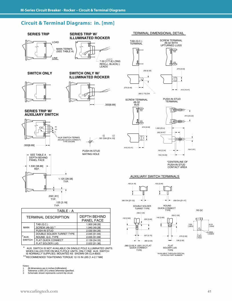
M-Series Circuit Breaker - Rocker – Circuit & Terminal Diagrams
Notes: 1 All dimensions are in inches [millimeters].2 Tolerance ±.020 [.51] unless otherwise specified.3 Schematic shown represents current trip circuit.
Circuit & Terminal Diagrams: in. [mm]
www.carlingtech.com42
M-Series Circuit Breaker - Rocker – Dimensional Specifications
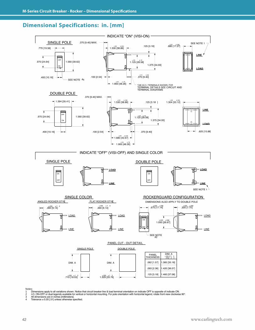
Notes: 1 Dimensions apply to all variations shown. Notice that circuit breaker line & load terminal orientation on indicate OFF is opposite of indicate ON.2 I-O, ON-OFF or dual legends available for vertical or horizontal mounting. For pole orientation with horizontal legend, rotate front view clockwise 90°.3 All dimensions are in inches [millimeters].4 Tolerance ± 0.20 [.51] unless otherwise specified.
Dimensional Specifications: in. [mm]
43www.carlingtech.com
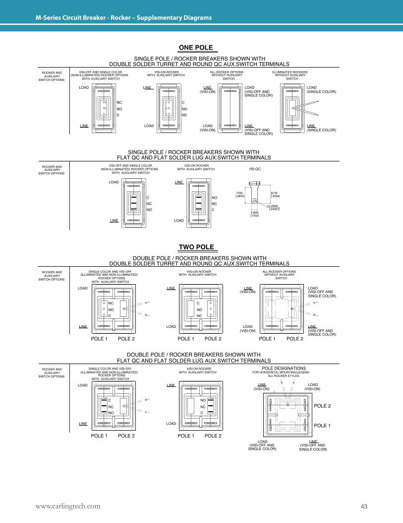
M-Series Circuit Breaker - Rocker – Supplementary Diagrams
www.carlingtech.com44
A-Series Circuit Breaker - Introduction
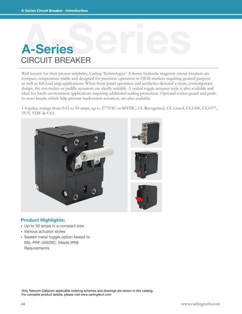
A-Series A-SeriesCIRCUIT BREAKERWell known for their proven reliability, Carling Technologies’ A-Series hydraulic magnetic circuit breakers are compact, temperature stable and designed for precision operation in OEM markets requiring general purpose as well as full load amp applications. When front panel operation and aesthetics demand a clean, contemporary design, the visi-rocker or paddle actuators are ideally suitable. A sealed toggle actuator style is also available and ideal for harsh environment applications requiring additional sealing protection. Optional rocker-guard and push-to-reset bezels, which help prevent inadvertent actuation, are also available.
1-6 poles; ratings from 0.02 to 50 amps, up to 277VAC or 80VDC; UL Recognized, UL Listed, UL1500, UL1077, TUV, VDE & CSA
Product Highlights: � Up to 50 amps in a compact size � Various actuator styles � Sealed metal toggle option tested to MIL-PRF-55629C. Meets IP68 Requirements
Only Telecom-Datacom applicable ordering schemes and drawings are shown in this catalog. For complete product details, please visit www.carlingtech.com
45www.carlingtech.com
A-Series Circuit Breaker - General Specifications
*Manufacturer reserves the right to change product specification without prior notice.
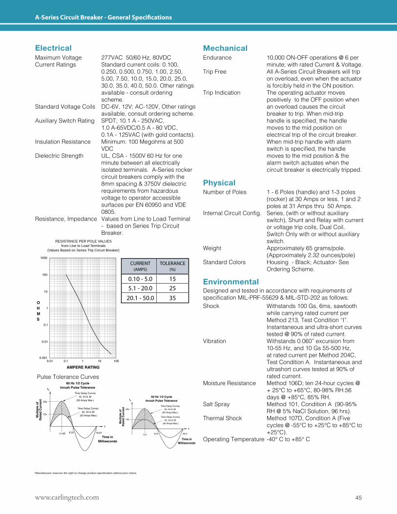
Electrical
RESISTANCE PER POLE VALUESfrom Line to Load Terminals
(Values Based on Series Trip Circuit Breaker)
Mechanical
Physical
EnvironmentalDesigned and tested in accordance with requirements of specificationMIL-PRF-55629&MIL-STD-202asfollows:
Maximum Voltage 277VAC 50/60 Hz, 80VDCCurrent Ratings Standard current coils: 0.100, 0.250, 0.500, 0.750, 1.00, 2.50, 5.00, 7.50, 10.0, 15.0, 20.0, 25.0, 30.0, 35.0, 40.0, 50.0. Other ratings available - consult ordering scheme.Standard Voltage Coils DC-6V, 12V; AC-120V, Other ratings available, consult ordering scheme.Auxiliary Switch Rating SPDT; 10.1 A - 250VAC, 1.0 A-65VDC/0.5 A - 80 VDC, 0.1A - 125VAC (with gold contacts).Insulation Resistance Minimum: 100 Megohms at 500 VDCDielectric Strength UL, CSA - 1500V 60 Hz for one minute between all electrically isolated terminals. A-Series rocker circuit breakers comply with the 8mm spacing & 3750V dielectric requirements from hazardous voltage to operator accessible surfaces per EN 60950 and VDE 0805.Resistance, Impedance Values from Line to Load Terminal - based on Series Trip Circuit Breaker.
Endurance 10,000 ON-OFF operations @ 6 per minute; with rated Current & Voltage. Trip Free All A-Series Circuit Breakers will trip on overload, even when the actuator is forcibly held in the ON position.Trip Indication The operating actuator moves positively to the OFF position when an overload causes the circuit breaker to trip. When mid-trip handleisspecified,thehandle moves to the mid position on electrical trip of the circuit breaker. When mid-trip handle with alarm switchisspecified,thehandle moves to the mid position & the alarm switch actuates when the circuit breaker is electrically tripped.
Number of Poles 1 - 6 Poles (handle) and 1-3 poles (rocker) at 30 Amps or less. 1 and 2 poles at 31 Amps thru 50 Amps.InternalCircuitConfig. Series,(withorwithoutauxiliary switch), Shunt and Relay with current or voltage trip coils, Dual Coil, Switch Only with or without auxiliary switch.Weight Approximately 65 grams/pole. (Approximately 2.32 ounces/pole)Standard Colors Housing - Black; Actuator- See Ordering Scheme.
Shock Withstands 100 Gs, 6ms, sawtooth while carrying rated current per Method 213, Test Condition “I”. Instantaneous and ultra-short curves tested @ 90% of rated current.Vibration Withstands 0.060” excursion from 10-55 Hz, and 10 Gs 55-500 Hz, at rated current per Method 204C, Test Condition A. Instantaneous and ultrashort curves tested at 90% of rated current.Moisture Resistance Method 106D; ten 24-hour cycles @ + 25°C to +65°C, 80-98% RH.56 days @ +85°C, 85% RH.Salt Spray Method 101, Condition A (90-95% RH @ 5% NaCl Solution, 96 hrs).Thermal Shock Method 107D, Condition A (Five cycles @ -55°C to +25°C to +85°C to +25°C).Operating Temperature -40° C to +85° C
Pulse Tolerance Curves
CURRENT (AMPS)
TOLERANCE (%)
0.10 - 5.0 155.1 - 20.0 25
20.1 - 50.0 35
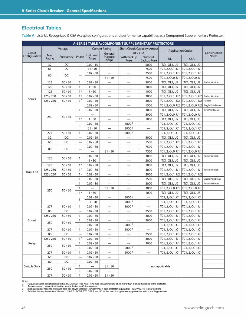
www.carlingtech.com46
A-Series Circuit Breaker - General Specifications
Electrical TablesTable A: Lists UL Recognized & CSA Accepted configurations and performance capabilities as a Component Supplementary Protector.
Notes: 1 Requires branch circuit backup with a UL LISTED Type K5 or RK5 fuse (15A minimum) at no more than 4 times the rating of the protector.2 Same as note 1, except that backup fuse is limited to 80 A maximum.3 2 pole protector required (with one pole per power line) for: 125/250 VAC, 1 pole protector required for : 125 VAC, 1Ø Power System.4 Satisfies the requirements of clause 11.2.8.2.5 of CSA STD C22.2 No 100 for the use of supplementary protectors with portable generators.
A-SERIES TABLE A: COMPONENT SUPPLEMENTARY PROTECTORS
Circuit Configuration
Voltage Current Rating Short Circuit Capacity (Amps)Application Codes
ConstructionNotesMax
Rating Frequency Phase Full LoadAmps
General Purpose
Amps
UL / CSAWith Backup
FuseWithout
Backup Fuse UL CSA
Series
32 DC --- 0.02 - 15 --- --- 5000 TC1, OL1, U2 TC1, OL1, U265 DC --- 31 - 50 --- --- 7500 TC1, 2, OL1, U1 TC1, 2, OL1, U1
80 DC ---0.02 - 30 --- --- 7500 TC1, 2, OL1, U1 TC1, 2, OL1, U1
--- 31 - 50 --- 7500 TC1, 2, OL0, U1 TC1, 2, OL0, U1125 50 / 60 1 0.02 - 30 --- --- 3000 TC1, OL1, U2 TC1, OL1, U2 Rocker Version
125 50 / 60 1 1 - 50 --- --- 2000 TC1, OL1, U2 TC1, OL1, U2125 50 / 60 1 4 1 - 50 --- --- 1000 TC1, OL1, U2 TC3, OL1, U3
125 / 250 50 / 60 1 3 0.02 - 30 --- --- 3000 TC1, 2, OL1, U2 TC1, 2, OL1, U2 Rocker Version
125 / 250 50 / 60 1 3 0.02 - 50 --- --- 3000 TC1, 2, OL1, U2 TC1, 2, OL1, U2 Handle
250 50 / 60
10.02 - 30 --- --- 1500 TC1, 2, OL0, U2 TC1, 2, OL0, U2 Single Pole Break
0.02 - 30 --- --- 3000 TC1, OL1, U2 TC1, OL1, U2 Two Pole Break
--- --- 3000 TC1, 2, OL0, U1 TC1, 2, OL0, U11 4 1 - 50 --- --- 1000 TC1, OL1, U2 TC3, OL1, U3
30.02 - 30 --- 5000 2 --- TC1, 2, OL1, C1 TC1, 2, OL1, C131 - 50 --- 2000 1 --- TC1, 2, OL1, C1 TC1, 2, OL1, C1
277 50 / 60 1 0.02 - 30 --- 5000 1 --- TC1, 2, OL1, C1 TC1, 2, OL1, C1
Dual Coil
32 DC --- 0.02 - 50 --- --- 5000 TC1, OL1, U2 TC1, OL1, U265 DC --- 0.02 - 50 --- --- 7500 TC1, 2, OL1, U1 TC1, 2, OL1, U1
80 DC ---0.02 - 30 --- --- 7500 TC1, 2, OL1, U1 TC1, 2, OL1, U1
--- 31 - 50 --- 7500 TC1, 2, OL0, U1 TC1, 2, OL0, U1
125 50 / 60 10.02 - 30 --- --- 3000 TC1, OL1, U2 TC1, OL1, U2 Rocker Version
1 - 50 --- --- 2000 TC1, OL1, U2 TC1, OL1, U2125 50 / 60 1 4 0.02 - 30 --- --- 1000 TC1, OL1, U2 TC3, OL1, U3
125 / 250 50 / 60 1 3 0.02 - 30 --- --- 3000 TC1, 2, OL1, U1 TC1, 2, OL1, U1 Rocker Version
125 / 250 50 / 60 1 3 0.02 - 50 --- --- 3000 TC1, 2, OL1, U2 TC1, 2, OL1, U2
250 50 / 60
1 0.02 - 30 --- --- 1500 TC1, OL0, U2 TC1, OL0, U2 Single Pole Break
1 0.02 - 30 --- --- 3000 TC1, OL1, U2 TC1, OL1, U2 Two Pole Break
1 --- 31 - 50 --- 3000 TC1, 2, OL0, U1 TC1, 2, OL0, U11 4 1 - 50 --- --- 1000 TC1, OL1, U2 TC3, OL1, U3
30.02 - 30 --- 5000 2 --- TC1, 2, OL1, C1 TC1, 2, OL1, C131 - 50 --- 2000 1 --- TC1, 2, OL1, C1 TC1, 2, OL1, C1
277 50 / 60 1 0.02 - 30 --- 5000 1 --- TC1, 2, OL1, U1 TC1, 2, OL1, U1
Shunt
80 DC --- 0.02 - 30 --- --- 7500 TC1, 2, OL1, U1 TC1, 2, OL1, U1125 / 250 50 / 60 1 0.02 - 30 --- --- 3000 TC1, 2, OL1, U1 TC1, 2, OL1, U1
250 50 / 601 0.02 - 30 --- --- 3000 TC1, 2, OL1, U1 TC1, 2, OL1, U13 0.02 - 30 --- 5000 2 --- TC1, 2, OL1, C1 TC1, 2, OL1, C1
277 50 / 60 1 0.02 - 30 --- 5000 1 --- TC1, 2, OL1, C1 TC1, 2, OL1, C1
Relay
80 DC --- 0.02 - 30 --- --- 7500 TC1, 2, OL1, U1 TC1, 2, OL1, U1125 / 250 50 / 60 1 3 0.02 - 30 --- --- 3000 TC1, 2, OL1, U1 TC1, 2, OL1, U1
250 50 / 601 0.02 - 30 --- --- 3000 TC1, 2, OL1, U1 TC1, 2, OL1, U13 0.02 - 30 --- 5000 2 --- TC1, 2, OL1, C1 TC1, 2, OL1, C1
277 50 / 60 1 0.02 - 30 --- 5000 1 --- TC1, 2, OL1, C1 TC1, 2, OL1, C1
Switch Only
65 DC --- 0.02 - 50 ---
not applicable80 DC --- 0.02 - 30 ---
250 50 / 601 --- 31 - 503 0.02 - 50 ---
277 50 / 60 1 0.02 - 30 31 - 50
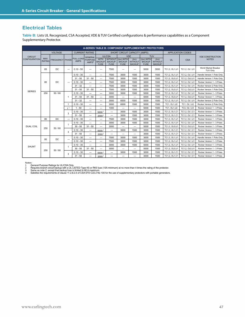
47www.carlingtech.com
A-Series Circuit Breaker - General Specifications
1
2
3
2
3
2
3
Electrical TablesTable B: Lists UL Recognized, CSA Accepted, VDE & TUV Certified configurations & performance capabilities as a Component Supplementary Protector.
Notes: 1 General Purpose Ratings for UL/CSA Only.2 Requires branch circuit backup with a UL LISTED Type K5 or RK5 fuse (15A minimum) at no more than 4 times the rating of the protector.3 Same as note 2, except that backup fuse is limited to 80 A maximum.4 Satisfies the requirements of clause 11.2.8.2.5 of CSA STD C22.2 No 100 for the use of supplementary protectors with portable generators.
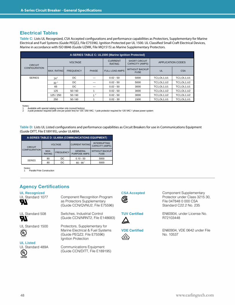
www.carlingtech.com48
A-Series Circuit Breaker - General Specifications
SERIES 14 1 DC --- 0.02 - 50 5000 TC1,OL1,U1 TC1,OL1,U1
32 1 DC --- 0.02 - 50 5000 TC1,OL1,U2 TC1,OL1,U2
65 DC --- 0.02 - 50 3000 TC1,OL1,U1 TC1,OL1,U1
125 50 / 60 1 0.02 - 50 3000 TC1,OL1,U2 TC1,OL1,U2
125 / 250 50 / 60 1 2 0.02 - 50 3000 TC1,OL1,U2 TC1,OL1,U2
250 50 / 60 1 0.02 - 30 1500 TC1,OL1,U1 TC1,OL1,U1
Notes:
1 Available with Special Catalog Number Only (consult factory)
2 2 pole protector required (with one per power line) for 125 / 250 VAC. 1 pole protector required for 125 VAC 1 phase power system
CSA
SHORT CIRCUIT CAPACITY (AMPS) APPLICATION CODES
A-SERIES TABLE C: UL1500 (Marine Ignition Protected)
UL
VOLTAGECIRCUIT
CONFIGURATION
CURRENT RATING
FULL LOAD AMPSWITHOUT BACKUP
FUSEMAX. RATING FREQUENCY PHASE
Electrical TablesTable C: Lists UL Recognized, CSA Accepted configurations and performance capabilities as Protectors, Supplementary for Marine Electrical and Fuel Systems (Guide PEQZ2, File E75596). Ignition Protected per UL 1500. UL Classified Small Craft Electrical Devices, Marine in accordance with ISO 8846 (Guide UZMK, File MQ1515) as Marine Supplementary Protectors.
Table D: Lists UL Listed configurations and performance capabilities as Circuit Breakers for use in Communications Equipment (Guide DITT, File E189195), under UL489A.
Notes: 1 Available with special catalog number only (consult factory).2 2 pole protector required (with one per power line) for 125 / 250 VAC. 1 pole protector required for 125 VAC 1 phase power system
Notes: 1 Parallel Pole Construction
Agency CertificationsUL RecognizedUL Standard 1077
UL Standard 508
UL Standard 1500
UL ListedUL Standard 489A
CSA Accepted
TUV Certified
VDE Certified
Component Recognition Program as Protectors Supplementary (Guide CCN/QVNU2, File E75596)
Switches, Industrial Control (Guide CCN/NRNT2, File E148683)
Protectors, Supplementary for Marine Electrical & Fuel Systems (Guide PEQZ2, File E75596) Ignition Protection
Communications Equipment (Guide CCN/DITT, File E189195)
Component Supplementary Protector under Class 3215 30, File 047848 0 000 CSA Standard C22.2 No. 235
EN60934, under License No. R72103448
EN60934, VDE 0642 under File No. 10537
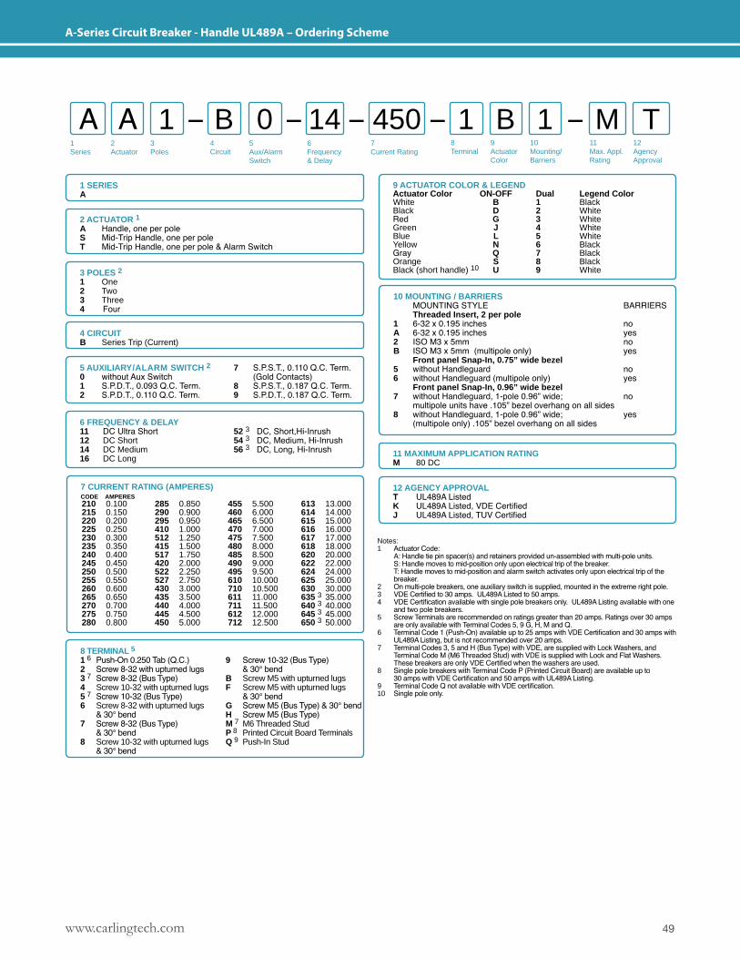
49www.carlingtech.com
A-Series Circuit Breaker - Handle UL489A – Ordering Scheme
1Series
2Actuator
3Poles
5Aux/Alarm Switch
6Frequency& Delay
7Current Rating
8Terminal
9ActuatorColor
10Mounting/Barriers
11Max. Appl. Rating
12AgencyApproval
4 Circuit
A A B 1 11 0 B M T14 450
1 SERIESA
2 ACTUATOR 1A Handle, one per poleS Mid-Trip Handle, one per poleT Mid-Trip Handle, one per pole & Alarm Switch
3 POLES 2 1 One2 Two3 Three4 Four
5 AUXILIARY/ALARM SWITCH 2 7 S.P.S.T., 0.110 Q.C. Term.0 without Aux Switch (Gold Contacts)1 S.P.D.T., 0.093 Q.C. Term. 8 S.P.S.T., 0.187 Q.C. Term.2 S.P.D.T., 0.110 Q.C. Term. 9 S.P.D.T., 0.187 Q.C. Term.
6 FREQUENCY & DELAY11 DC Ultra Short12 DC Short14 DC Medium16 DC Long
52 3 DC, Short,Hi-Inrush 54 3 DC, Medium, Hi-Inrush 56 3 DC, Long, Hi-Inrush
12 AGENCY APPROVALT UL489A ListedK UL489A Listed, VDE CertifiedJ UL489A Listed, TUV Certified
11 MAXIMUM APPLICATION RATINGM 80 DC
9 ACTUATOR COLOR & LEGENDActuator Color ON-OFF Dual Legend ColorWhite B 1 BlackBlack D 2 WhiteRed G 3 WhiteGreen J 4 WhiteBlue L 5 WhiteYellow N 6 BlackGray Q 7 BlackOrange S 8 BlackBlack (short handle) 10 U 9 White
Notes: 1 Actuator Code: A: Handle tie pin spacer(s) and retainers provided un-assembled with multi-pole units. S: Handle moves to mid-position only upon electrical trip of the breaker. T: Handle moves to mid-position and alarm switch activates only upon electrical trip of the breaker.2 On multi-pole breakers, one auxiliary switch is supplied, mounted in the extreme right pole.3 VDE Certified to 30 amps. UL489A Listed to 50 amps.4 VDE Certification available with single pole breakers only. UL489A Listing available with one and two pole breakers.5 Screw Terminals are recommended on ratings greater than 20 amps. Ratings over 30 amps are only available with Terminal Codes 5, 9 G, H, M and Q.6 Terminal Code 1 (Push-On) available up to 25 amps with VDE Certification and 30 amps with UL489A Listing, but is not recommended over 20 amps.7 Terminal Codes 3, 5 and H (Bus Type) with VDE, are supplied with Lock Washers, and Terminal Code M (M6 Threaded Stud) with VDE is supplied with Lock and Flat Washers. These breakers are only VDE Certified when the washers are used. 8 Single pole breakers with Terminal Code P (Printed Circuit Board) are available up to 30 amps with VDE Certification and 50 amps with UL489A Listing. 9 Terminal Code Q not available with VDE certification.10 Single pole only.
4 CIRCUITB Series Trip (Current)
8 TERMINAL 51 6 Push-On 0.250 Tab (Q.C.) 9 Screw 10-32 (Bus Type)2 Screw 8-32 with upturned lugs & 30° bend3 7 Screw 8-32 (Bus Type) B Screw M5 with upturned lugs4 Screw 10-32 with upturned lugs F Screw M5 with upturned lugs5 7 Screw 10-32 (Bus Type) & 30° bend 6 Screw 8-32 with upturned lugs G Screw M5 (Bus Type) & 30° bend & 30° bend H Screw M5 (Bus Type)7 Screw 8-32 (Bus Type) M 7 M6 Threaded Stud & 30° bend P 8 Printed Circuit Board Terminals8 Screw 10-32 with upturned lugs Q 9 Push-In Stud & 30° bend
10 MOUNTING / BARRIERS MOUNTING STYLE BARRIERS Threaded Insert, 2 per pole1 6-32 x 0.195 inches noA 6-32 x 0.195 inches yes 2 ISO M3 x 5mm no B ISO M3 x 5mm (multipole only) yes Front panel Snap-In, 0.75” wide bezel 5 without Handleguard no 6 without Handleguard (multipole only) yes Front panel Snap-In, 0.96” wide bezel 7 without Handleguard, 1-pole 0.96” wide; no multipole units have .105” bezel overhang on all sides 8 without Handleguard, 1-pole 0.96” wide; yes (multipole only) .105” bezel overhang on all sides
7 CURRENT RATING (AMPERES)CODE AMPERES 210 0.100215 0.150220 0.200225 0.250230 0.300235 0.350240 0.400245 0.450250 0.500255 0.550260 0.600265 0.650270 0.700275 0.750280 0.800
285 0.850290 0.900295 0.950410 1.000512 1.250415 1.500517 1.750420 2.000522 2.250527 2.750430 3.000435 3.500440 4.000445 4.500450 5.000
455 5.500460 6.000465 6.500470 7.000475 7.500480 8.000485 8.500490 9.000495 9.500610 10.000710 10.500611 11.000711 11.500612 12.000712 12.500
613 13.000614 14.000615 15.000616 16.000617 17.000618 18.000620 20.000622 22.000624 24.000625 25.000630 30.000635 3 35.000640 3 40.000645 3 45.000650 3 50.000
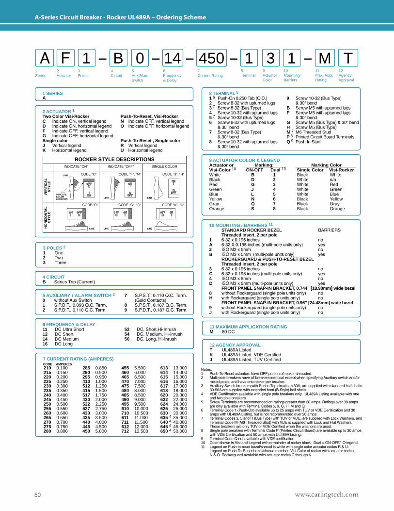
www.carlingtech.com50
A-Series Circuit Breaker - Rocker UL489A – Ordering Scheme
1Series
2Actuator
3Poles
5Aux/Alarm Switch
6Frequency& Delay
7Current Rating
8Terminal
9ActuatorColor
10Mounting/Barriers
11Max. Appl. Rating
12AgencyApproval
4 Circuit
A F B 1 11 0 3 M T14 450
1 SERIESA
10 MOUNTING / BARRIERS 11
STANDARD ROCKER BEZEL BARRIERS Threaded Insert, 2 per pole1 6-32 x 0.195 inches no A 6-32 X 0.195 inches (multi-pole units only) yes 2 ISO M3 x 5mm no B ISO M3 x 5mm (multi-pole units only) yes ROCKERGUARD & PUSH-TO-RESET BEZEL Threaded Insert, 2 per pole3 6-32 x 0.195 inches no C 6-32 x 0.195 inches (multi-pole units only) yes4 ISO M3 x 5mm no D ISO M3 x 5mm (multi-pole units only) yes FRONT PANEL SNAP-IN BRACKET, 0.744” [18.90mm] wide bezel 8 without Rockerguard (single pole units only) no H with Rockerguard (single pole units only) no FRONT PANEL SNAP-IN BRACKET, 0.96” [24.48mm] wide bezel 9 without Rockerguard (single pole units only) no J with Rockerguard (single pole units only) no
Notes: 1 Push-To-Reset actuators have OFF portion of rocker shrouded.2 Multi-pole breakers have all breakers identical except when specifying Auxiliary switch and/or mixed poles, and have one rocker per breaker.3 Auxiliary Switch breakers with Series Trip circuits: ≤ 30A, are supplied with standard half shells. 30-50A are supplied with extended boat (B-Style) half shells.4 VDE Certification available with single pole breakers only. UL489A Listing available with one and two pole breakers.5 Screw Terminals are recommended on ratings greater than 20 amps. Ratings over 30 amps are only available with Terminal Codes 5, 9, G, H, M and Q.6 Terminal Code 1 (Push-On) available up to 25 amps with TUV or VDE Certification and 30 amps with UL489A Listing, but is not recommended over 20 amps.7 Terminal Codes 3, 5 and H (Bus Type) with TUV or VDE, are supplied with Lock Washers, and Terminal Code M (M6 Threaded Stud) with VDE is supplied with Lock and Flat Washers. These breakers are only TUV or VDE Certified when the washers are used. 8 Single pole breakers with Terminal Code P (Printed Circuit Board) are available up to 30 amps with VDE Certification and 50 amps with UL489A Listing. 9 Terminal Code Q not available with VDE certification.10 Color shown is Visi and Legend with remainder of rocker black. Dual = ON-OFF/I-O legend.11 Legend on Push-to-reset bezel/shroud is white with single color actuator codes R & U. Legend on Push-To-Reset bezel/shroud matches Visi-Color of rocker with actuator codes N & O. Rockerguard available with actuator codes C through K
2 ACTUATOR 1Two Color Visi-Rocker Push-To-Reset, Visi-Rocker C Indicate ON, vertical legend N Indicate OFF, vertical legendD Indicate ON, horizontal legend O Indicate OFF, horizontal legendF Indicate OFF, vertical legendG Indicate OFF, horizontal legendSingle color Push-To-Reset , Single colorJ Vertical legend R Vertical legendK Horizontal legend U Horizontal legend
9 ACTUATOR COLOR & LEGEND Actuator or Marking: Marking Color Visi-Color 10 ON-OFF Dual 10 Single Color Visi-Rocker White B 1 Black WhiteBlack D 2 White n/aRed G 3 White RedGreen J 4 White GreenBlue L 5 White BlueYellow N 6 Black YellowGray Q 7 Black GrayOrange S 8 Black Orange
3 POLES 2 1 One2 Two3 Three
5 AUXILIARY / ALARM SWITCH 2 7 S.P.S.T., 0.110 Q.C. Term.0 without Aux Switch (Gold Contacts)1 S.P.D.T., 0.093 Q.C. Term. 8 S.P.S.T., 0.187 Q.C. Term.2 S.P.D.T., 0.110 Q.C. Term. 9 S.P.D.T., 0.187 Q.C. Term.
6 FREQUENCY & DELAY11 DC Ultra Short12 DC Short14 DC Medium16 DC Long
52 DC, Short,Hi-Inrush 54 DC, Medium, Hi-Inrush 56 DC, Long, Hi-Inrush
12 AGENCY APPROVALT UL489A ListedK UL489A Listed, VDE CertifiedJ UL489A Listed, TUV Certified
11 MAXIMUM APPLICATION RATINGM 80 DC
4 CIRCUITB Series Trip (Current)
8 TERMINAL 51 6 Push-On 0.250 Tab (Q.C.) 9 Screw 10-32 (Bus Type)2 Screw 8-32 with upturned lugs & 30° bend3 7 Screw 8-32 (Bus Type) B Screw M5 with upturned lugs4 Screw 10-32 with upturned lugs F Screw M5 with upturned lugs5 7 Screw 10-32 (Bus Type) & 30° bend 6 Screw 8-32 with upturned lugs G Screw M5 (Bus Type) & 30° bend & 30° bend H Screw M5 (Bus Type)7 Screw 8-32 (Bus Type) M 7 M6 Threaded Stud & 30° bend P 8 Printed Circuit Board Terminals8 Screw 10-32 with upturned lugs Q 9 Push-In Stud & 30° bend
7 CURRENT RATING (AMPERES)CODE AMPERES 210 0.100215 0.150220 0.200225 0.250230 0.300235 0.350240 0.400245 0.450250 0.500255 0.550260 0.600265 0.650270 0.700275 0.750280 0.800
285 0.850290 0.900295 0.950410 1.000512 1.250415 1.500517 1.750420 2.000522 2.250527 2.750430 3.000435 3.500440 4.000445 4.500450 5.000
455 5.500460 6.000465 6.500470 7.000475 7.500480 8.000485 8.500490 9.000495 9.500610 10.000710 10.500611 11.000711 11.500612 12.000712 12.500
613 13.000614 14.000615 15.000616 16.000617 17.000618 18.000620 20.000622 22.000624 24.000625 25.000630 30.000635 4 35.000640 4 40.000645 4 45.000650 4 50.000
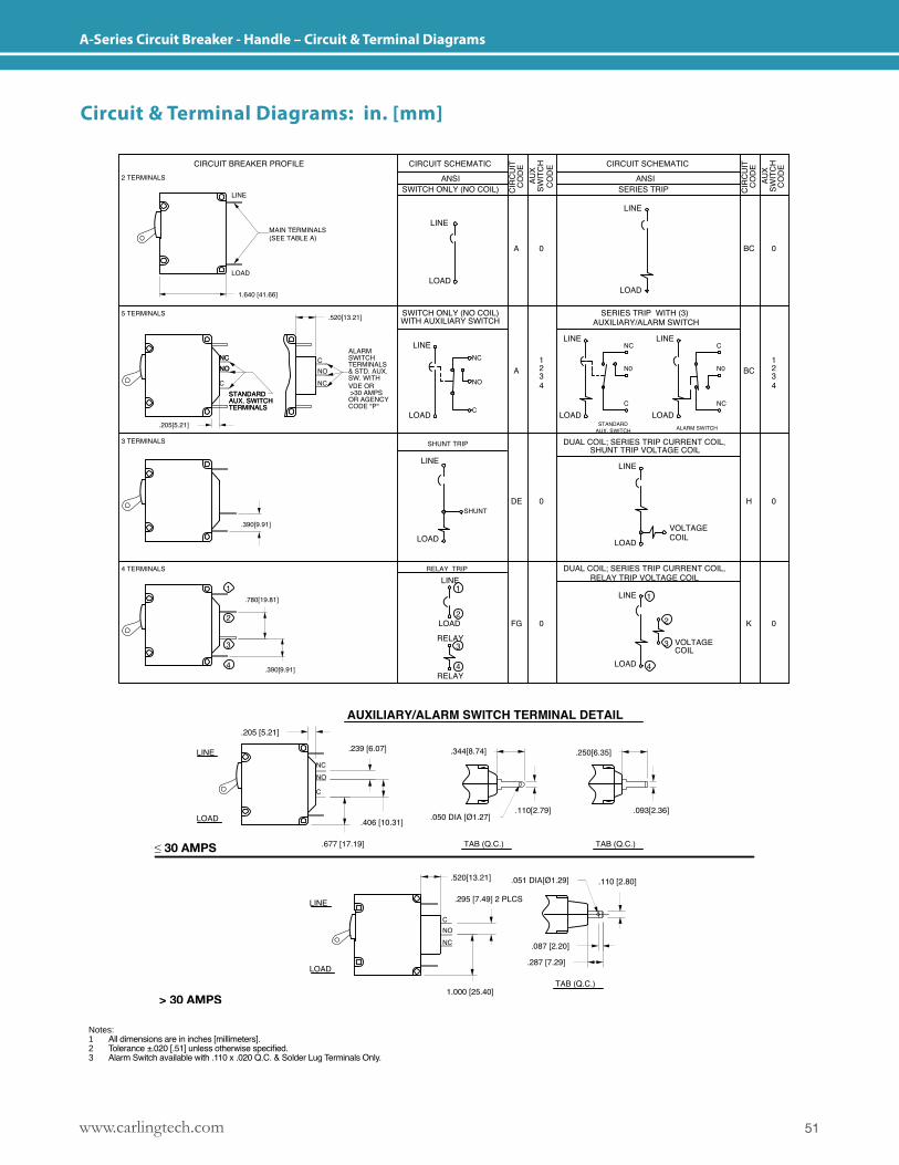
51www.carlingtech.com
A-Series Circuit Breaker - Handle – Circuit & Terminal Diagrams
Notes: 1 All dimensions are in inches [millimeters].2 Tolerance ±.020 [.51] unless otherwise specified.3 Alarm Switch available with .110 x .020 Q.C. & Solder Lug Terminals Only.
Circuit & Terminal Diagrams: in. [mm]
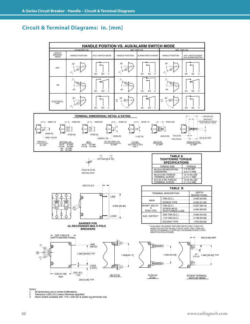
www.carlingtech.com52
A-Series Circuit Breaker - Handle – Circuit & Terminal Diagrams
Notes: 1 All dimensions are in inches [millimeters].2 Tolerance ±.020 [.51] unless otherwise specified.3 Alarm Switch available with .110 x .020 QC & solder lug terminals only.
Circuit & Terminal Diagrams: in. [mm]
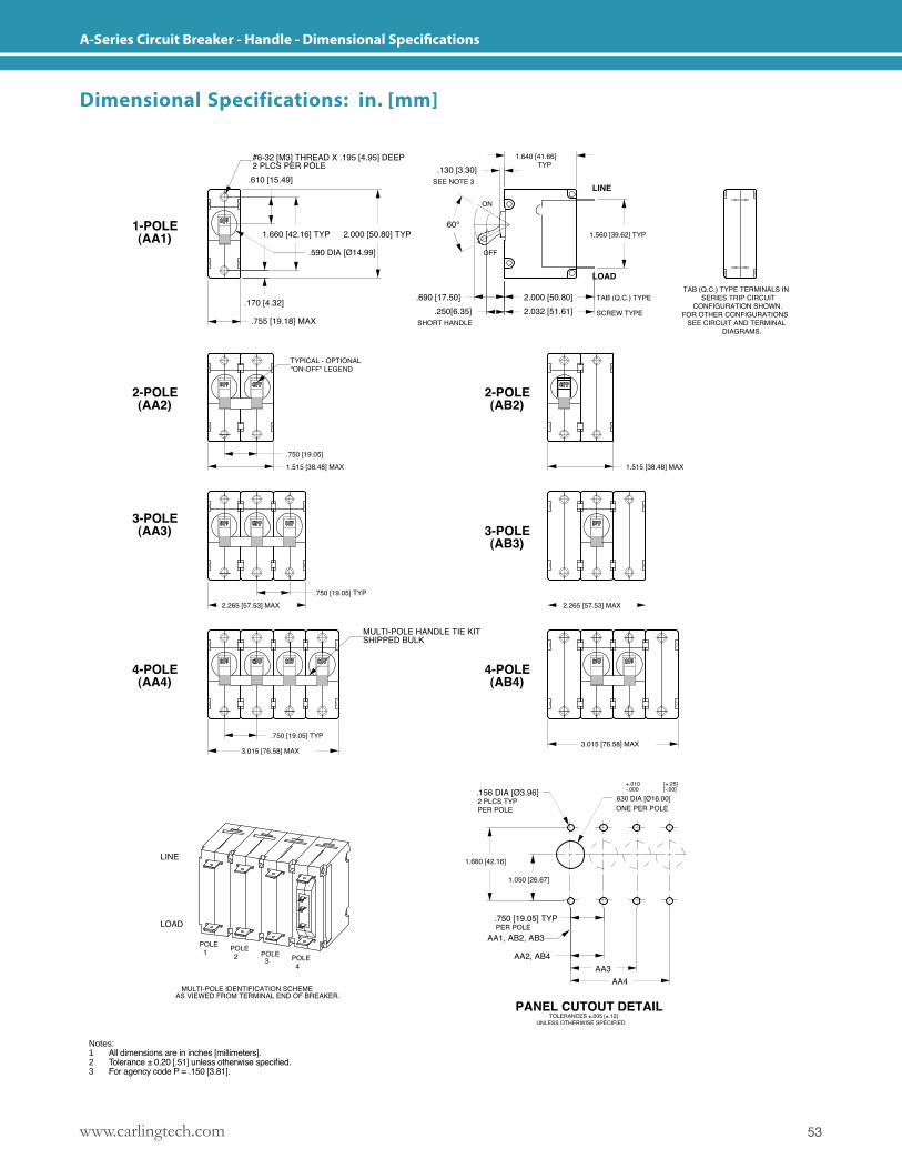
53www.carlingtech.com
A-Series Circuit Breaker - Handle - Dimensional Specifications
Notes: 1 All dimensions are in inches [millimeters].2 Tolerance ± 0.20 [.51] unless otherwise specified.3 For agency code P = .150 [3.81].
Dimensional Specifications: in. [mm]
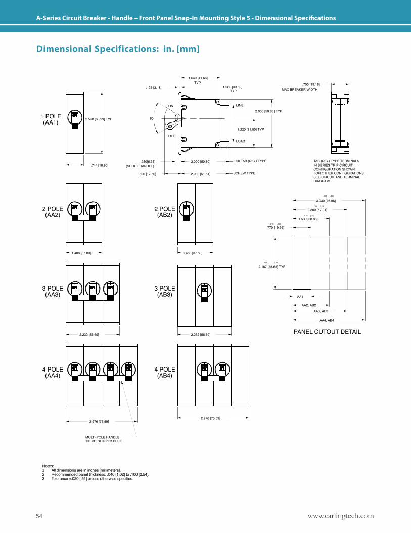
www.carlingtech.com54
A-Series Circuit Breaker - Handle – Front Panel Snap-In Mounting Style 5 - Dimensional Specifications
Notes: 1 All dimensions are in inches [millimeters].2 Recommended panel thickness: .040 [1.02] to .100 [2.54].3 Tolerance ±.020 [.51] unless otherwise specified.
Dimensional Specifications: in. [mm]
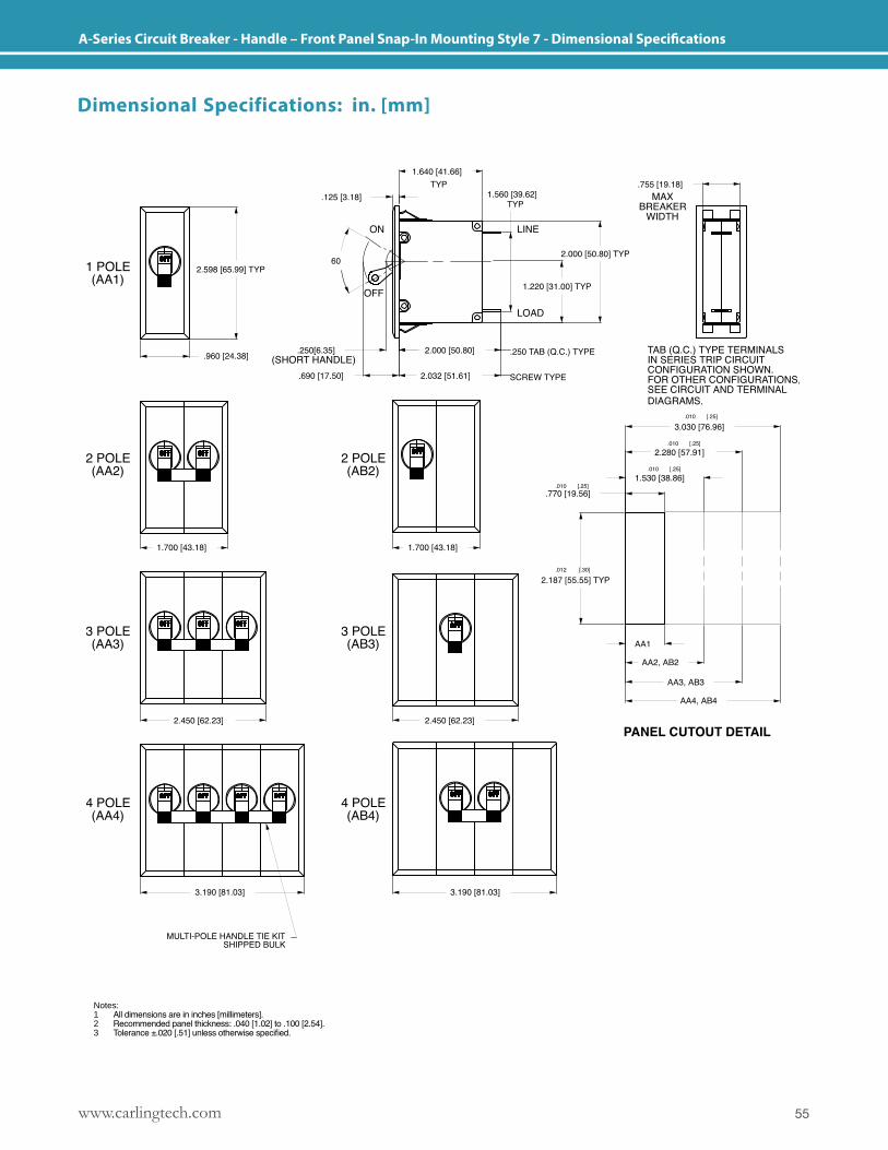
55www.carlingtech.com
A-Series Circuit Breaker - Handle – Front Panel Snap-In Mounting Style 7 - Dimensional Specifications
Notes: 1 All dimensions are in inches [millimeters].2 Recommended panel thickness: .040 [1.02] to .100 [2.54].3 Tolerance ±.020 [.51] unless otherwise specified.
Dimensional Specifications: in. [mm]
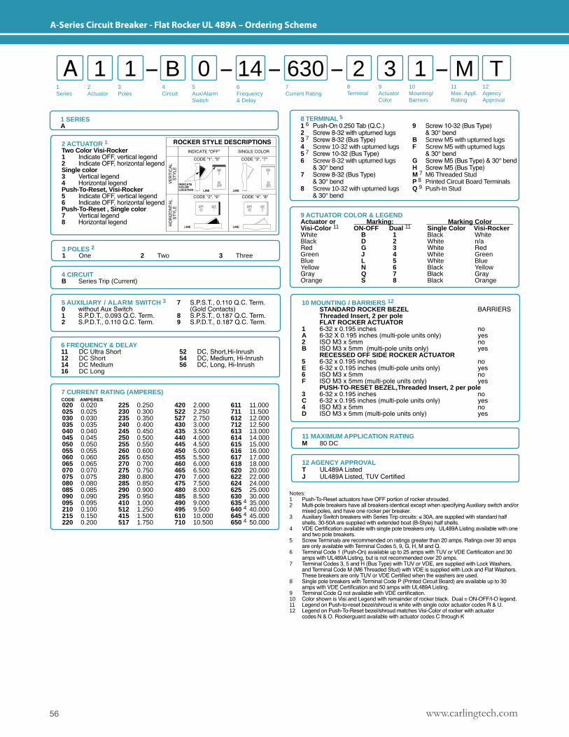
www.carlingtech.com56
A-Series Circuit Breaker - Flat Rocker UL 489A – Ordering Scheme
1Series
2Actuator
3Poles
5Aux/Alarm Switch
6Frequency& Delay
7Current Rating
8Terminal
9ActuatorColor
10Mounting/Barriers
11Max. Appl. Rating
12AgencyApproval
4 Circuit
A 1 B 2 11 0 3 M T14 630
1 SERIESA
12 AGENCY APPROVALT UL489A ListedJ UL489A Listed, TUV Certified
11 MAXIMUM APPLICATION RATINGM 80 DC
Notes: 1 Push-To-Reset actuators have OFF portion of rocker shrouded.2 Multi-pole breakers have all breakers identical except when specifying Auxiliary switch and/or mixed poles, and have one rocker per breaker.3 Auxiliary Switch breakers with Series Trip circuits: ≤ 30A, are supplied with standard half shells. 30-50A are supplied with extended boat (B-Style) half shells.4 VDE Certification available with single pole breakers only. UL489A Listing available with one and two pole breakers.5 Screw Terminals are recommended on ratings greater than 20 amps. Ratings over 30 amps are only available with Terminal Codes 5, 9, G, H, M and Q.6 Terminal Code 1 (Push-On) available up to 25 amps with TUV or VDE Certification and 30 amps with UL489A Listing, but is not recommended over 20 amps.7 Terminal Codes 3, 5 and H (Bus Type) with TUV or VDE, are supplied with Lock Washers, and Terminal Code M (M6 Threaded Stud) with VDE is supplied with Lock and Flat Washers. These breakers are only TUV or VDE Certified when the washers are used. 8 Single pole breakers with Terminal Code P (Printed Circuit Board) are available up to 30 amps with VDE Certification and 50 amps with UL489A Listing. 9 Terminal Code Q not available with VDE certification.10 Color shown is Visi and Legend with remainder of rocker black. Dual = ON-OFF/I-O legend.11 Legend on Push-to-reset bezel/shroud is white with single color actuator codes R & U.12 Legend on Push-To-Reset bezel/shroud matches Visi-Color of rocker with actuator codes N & O. Rockerguard available with actuator codes C through K
3 POLES 2 1 One 2 Two 3 Three
2 ACTUATOR 1Two Color Visi-Rocker1 Indicate OFF, vertical legend2 Indicate OFF, horizontal legendSingle color 3 Vertical legend4 Horizontal legendPush-To-Reset, Visi-Rocker5 Indicate OFF, vertical legend6 Indicate OFF, horizontal legendPush-To-Reset , Single color 7 Vertical legend8 Horizontal legend
10 MOUNTING / BARRIERS 12
STANDARD ROCKER BEZEL BARRIERS Threaded Insert, 2 per pole FLAT ROCKER ACTUATOR1 6-32 x 0.195 inches no A 6-32 X 0.195 inches (multi-pole units only) yes 2 ISO M3 x 5mm no B ISO M3 x 5mm (multi-pole units only) yes RECESSED OFF SIDE ROCKER ACTUATOR5 6-32 x 0.195 inches no E 6-32 x 0.195 inches (multi-pole units only) yes 6 ISO M3 x 5mm no F ISO M3 x 5mm (multi-pole units only) yes PUSH-TO-RESET BEZEL,Threaded Insert, 2 per pole3 6-32 x 0.195 inches no C 6-32 x 0.195 inches (multi-pole units only) yes 4 ISO M3 x 5mm no D ISO M3 x 5mm (multi-pole units only) yes
5 AUXILIARY / ALARM SWITCH 3 7 S.P.S.T., 0.110 Q.C. Term.0 without Aux Switch (Gold Contacts)1 S.P.D.T., 0.093 Q.C. Term. 8 S.P.S.T., 0.187 Q.C. Term.2 S.P.D.T., 0.110 Q.C. Term. 9 S.P.D.T., 0.187 Q.C. Term.
6 FREQUENCY & DELAY11 DC Ultra Short12 DC Short14 DC Medium16 DC Long
52 DC, Short,Hi-Inrush 54 DC, Medium, Hi-Inrush 56 DC, Long, Hi-Inrush
4 CIRCUIT B Series Trip (Current)
7 CURRENT RATING (AMPERES)CODE AMPERES 020 0.020025 0.025030 0.030035 0.035040 0.040045 0.045050 0.050055 0.055060 0.060065 0.065070 0.070075 0.075080 0.080085 0.085090 0.090095 0.095210 0.100215 0.150220 0.200
225 0.250230 0.300235 0.350240 0.400245 0.450250 0.500255 0.550260 0.600265 0.650270 0.700275 0.750280 0.800285 0.850290 0.900295 0.950410 1.000512 1.250415 1.500517 1.750
420 2.000522 2.250527 2.750430 3.000435 3.500440 4.000445 4.500450 5.000455 5.500460 6.000465 6.500470 7.000475 7.500480 8.000485 8.500490 9.000495 9.500610 10.000710 10.500
611 11.000711 11.500612 12.000712 12.500613 13.000614 14.000615 15.000616 16.000617 17.000618 18.000620 20.000622 22.000624 24.000625 25.000630 30.000635 4 35.000640 4 40.000645 4 45.000650 4 50.000
9 ACTUATOR COLOR & LEGEND Actuator or Marking: Marking Color Visi-Color 11 ON-OFF Dual 11 Single Color Visi-Rocker White B 1 Black WhiteBlack D 2 White n/aRed G 3 White RedGreen J 4 White GreenBlue L 5 White BlueYellow N 6 Black YellowGray Q 7 Black GrayOrange S 8 Black Orange
8 TERMINAL 51 6 Push-On 0.250 Tab (Q.C.) 9 Screw 10-32 (Bus Type)2 Screw 8-32 with upturned lugs & 30° bend3 7 Screw 8-32 (Bus Type) B Screw M5 with upturned lugs4 Screw 10-32 with upturned lugs F Screw M5 with upturned lugs5 7 Screw 10-32 (Bus Type) & 30° bend 6 Screw 8-32 with upturned lugs G Screw M5 (Bus Type) & 30° bend & 30° bend H Screw M5 (Bus Type)7 Screw 8-32 (Bus Type) M 7 M6 Threaded Stud & 30° bend P 8 Printed Circuit Board Terminals8 Screw 10-32 with upturned lugs Q 9 Push-In Stud & 30° bend
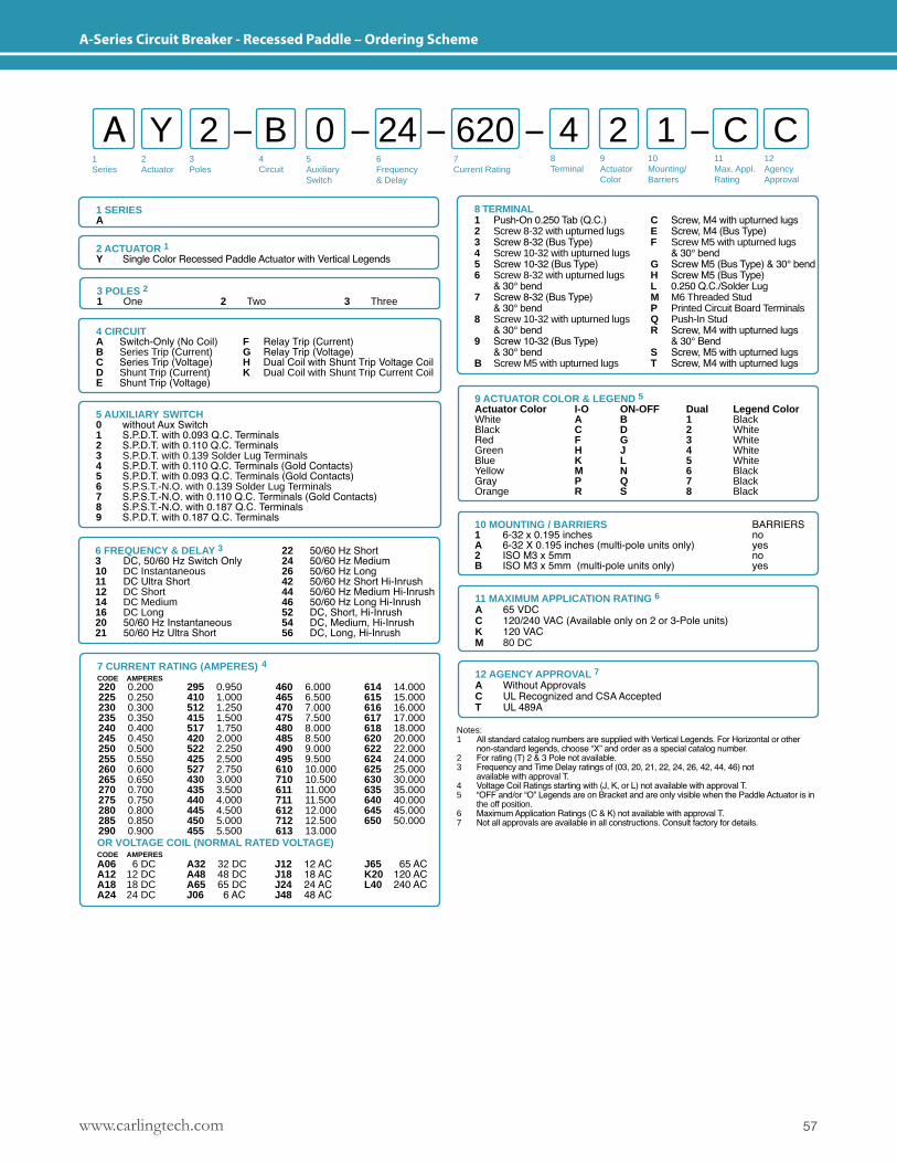
57www.carlingtech.com
A-Series Circuit Breaker - Recessed Paddle – Ordering Scheme
1Series
2Actuator
3Poles
5Auxiliary Switch
6Frequency& Delay
7Current Rating
8Terminal
9ActuatorColor
10Mounting/Barriers
11Max. Appl. Rating
12AgencyApproval
4 Circuit
A Y B 4 12 0 2 C C24 620
1 SERIESA
12 AGENCY APPROVAL 7A Without ApprovalsC UL Recognized and CSA Accepted T UL 489A
11 MAXIMUM APPLICATION RATING 6A 65 VDCC 120/240 VAC (Available only on 2 or 3-Pole units)K 120 VACM 80 DC
Notes: 1 All standard catalog numbers are supplied with Vertical Legends. For Horizontal or other non-standard legends, choose “X” and order as a special catalog number.2 For rating (T) 2 & 3 Pole not available.3 Frequency and Time Delay ratings of (03, 20, 21, 22, 24, 26, 42, 44, 46) not available with approval T.4 Voltage Coil Ratings starting with (J, K, or L) not available with approval T.5 “OFF and/or “O” Legends are on Bracket and are only visible when the Paddle Actuator is in the off position.6 Maximum Application Ratings (C & K) not available with approval T.7 Not all approvals are available in all constructions. Consult factory for details.
3 POLES 2 1 One 2 Two 3 Three
2 ACTUATOR 1Y Single Color Recessed Paddle Actuator with Vertical Legends
10 MOUNTING / BARRIERS BARRIERS1 6-32 x 0.195 inches no A 6-32 X 0.195 inches (multi-pole units only) yes 2 ISO M3 x 5mm no B ISO M3 x 5mm (multi-pole units only) yes
5 AUXILIARY SWITCH 0 without Aux Switch 1 S.P.D.T. with 0.093 Q.C. Terminals 2 S.P.D.T. with 0.110 Q.C. Terminals3 S.P.D.T. with 0.139 Solder Lug Terminals4 S.P.D.T. with 0.110 Q.C. Terminals (Gold Contacts)5 S.P.D.T. with 0.093 Q.C. Terminals (Gold Contacts)6 S.P.S.T.-N.O. with 0.139 Solder Lug Terminals7 S.P.S.T.-N.O. with 0.110 Q.C. Terminals (Gold Contacts)8 S.P.S.T.-N.O. with 0.187 Q.C. Terminals9 S.P.D.T. with 0.187 Q.C. Terminals
6 FREQUENCY & DELAY 33 DC, 50/60 Hz Switch Only10 DC Instantaneous11 DC Ultra Short12 DC Short14 DC Medium16 DC Long20 50/60 Hz Instantaneous21 50/60 Hz Ultra Short
22 50/60 Hz Short24 50/60 Hz Medium26 50/60 Hz Long 42 50/60 Hz Short Hi-Inrush44 50/60 Hz Medium Hi-Inrush46 50/60 Hz Long Hi-Inrush52 DC, Short, Hi-Inrush 54 DC, Medium, Hi-Inrush 56 DC, Long, Hi-Inrush
4 CIRCUIT A Switch-Only (No Coil) F Relay Trip (Current)B Series Trip (Current) G Relay Trip (Voltage)C Series Trip (Voltage) H Dual Coil with Shunt Trip Voltage CoilD Shunt Trip (Current) K Dual Coil with Shunt Trip Current CoilE Shunt Trip (Voltage)
8 TERMINAL1 Push-On 0.250 Tab (Q.C.) C Screw, M4 with upturned lugs2 Screw 8-32 with upturned lugs E Screw, M4 (Bus Type)3 Screw 8-32 (Bus Type) F Screw M5 with upturned lugs4 Screw 10-32 with upturned lugs & 30° bend 5 Screw 10-32 (Bus Type) G Screw M5 (Bus Type) & 30° bend6 Screw 8-32 with upturned lugs H Screw M5 (Bus Type) & 30° bend L 0.250 Q.C./Solder Lug7 Screw 8-32 (Bus Type) M M6 Threaded Stud & 30° bend P Printed Circuit Board Terminals8 Screw 10-32 with upturned lugs Q Push-In Stud & 30° bend R Screw, M4 with upturned lugs 9 Screw 10-32 (Bus Type) & 30° Bend & 30° bend S Screw, M5 with upturned lugsB Screw M5 with upturned lugs T Screw, M4 with upturned lugs
7 CURRENT RATING (AMPERES) 4CODE AMPERES
OR VOLTAGE COIL (NORMAL RATED VOLTAGE) CODE AMPERES A06 6 DC A32 32 DC J12 12 AC J65 65 ACA12 12 DC A48 48 DC J18 18 AC K20 120 ACA18 18 DC A65 65 DC J24 24 AC L40 240 ACA24 24 DC J06 6 AC J48 48 AC
220 0.200225 0.250230 0.300235 0.350240 0.400245 0.450250 0.500255 0.550260 0.600265 0.650270 0.700275 0.750280 0.800285 0.850290 0.900
295 0.950410 1.000512 1.250415 1.500517 1.750420 2.000522 2.250425 2.500527 2.750430 3.000435 3.500440 4.000445 4.500450 5.000455 5.500
460 6.000465 6.500470 7.000475 7.500480 8.000485 8.500490 9.000495 9.500610 10.000710 10.500611 11.000711 11.500612 12.000712 12.500613 13.000
614 14.000615 15.000616 16.000617 17.000618 18.000620 20.000622 22.000624 24.000625 25.000630 30.000635 35.000640 40.000645 45.000650 50.000
9 ACTUATOR COLOR & LEGEND 5Actuator Color I-O ON-OFF Dual Legend ColorWhite A B 1 BlackBlack C D 2 WhiteRed F G 3 WhiteGreen H J 4 WhiteBlue K L 5 WhiteYellow M N 6 BlackGray P Q 7 BlackOrange R S 8 Black
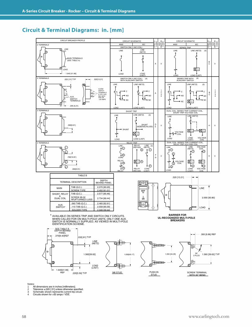
www.carlingtech.com58
A-Series Circuit Breaker - Rocker – Circuit & Terminal Diagrams
Notes: 1 All dimensions are in inches [millimeters].2 Tolerance ±.020 [.51] unless otherwise specified.3 Schematic shown represents current trip circuit.4 Circuits shown for >30 amps / VDE.
Circuit & Terminal Diagrams: in. [mm]
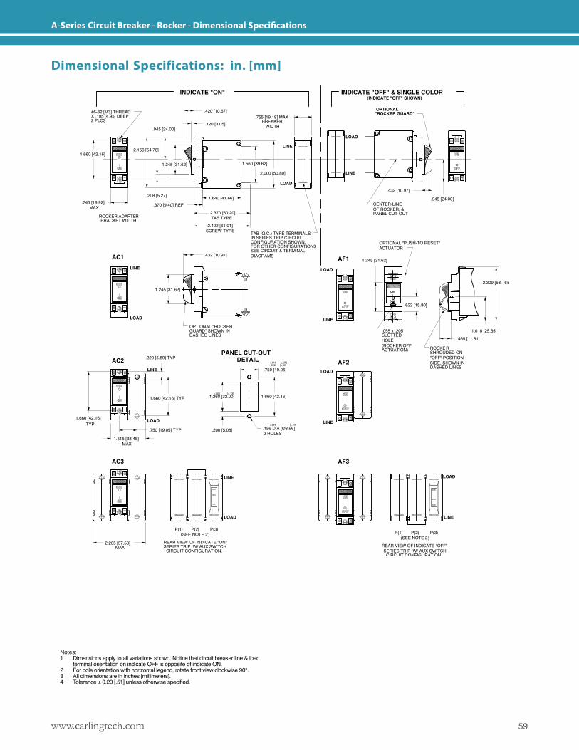
59www.carlingtech.com
A-Series Circuit Breaker - Rocker - Dimensional Specifications
Notes: 1 Dimensions apply to all variations shown. Notice that circuit breaker line & load terminal orientation on indicate OFF is opposite of indicate ON.2 For pole orientation with horizontal legend, rotate front view clockwise 90°.3 All dimensions are in inches [millimeters].4 Tolerance ± 0.20 [.51] unless otherwise specified.
Dimensional Specifications: in. [mm]
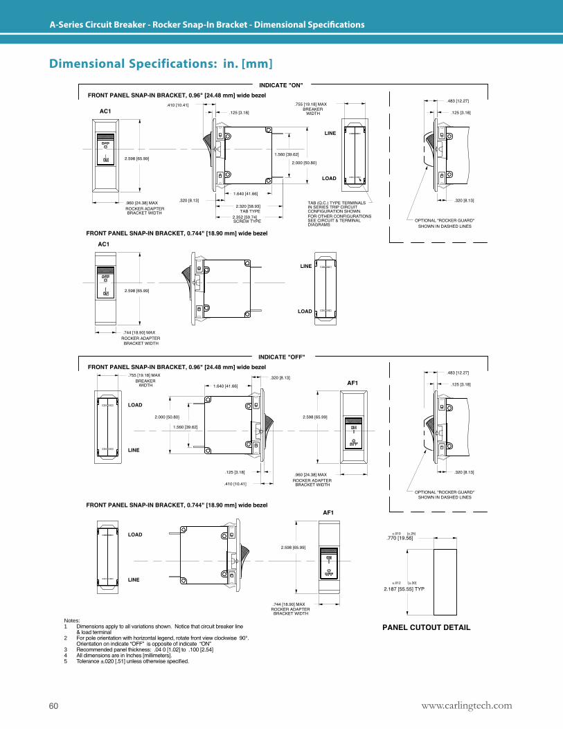
www.carlingtech.com60
A-Series Circuit Breaker - Rocker Snap-In Bracket - Dimensional Specifications
Notes: 1 Dimensions apply to all variations shown. Notice that circuit breaker line & load terminal 2 For pole orientation with horizontal legend, rotate front view clockwise 90°. Orientation on indicate “OFF” is opposite of indicate “ON” 3 Recommended panel thickness: .04 0 [1.02] to .100 [2.54]4 All dimensions are in Inches [millimeters]. 5 Tolerance ±.020 [.51] unless otherwise specified.
Dimensional Specifications: in. [mm]
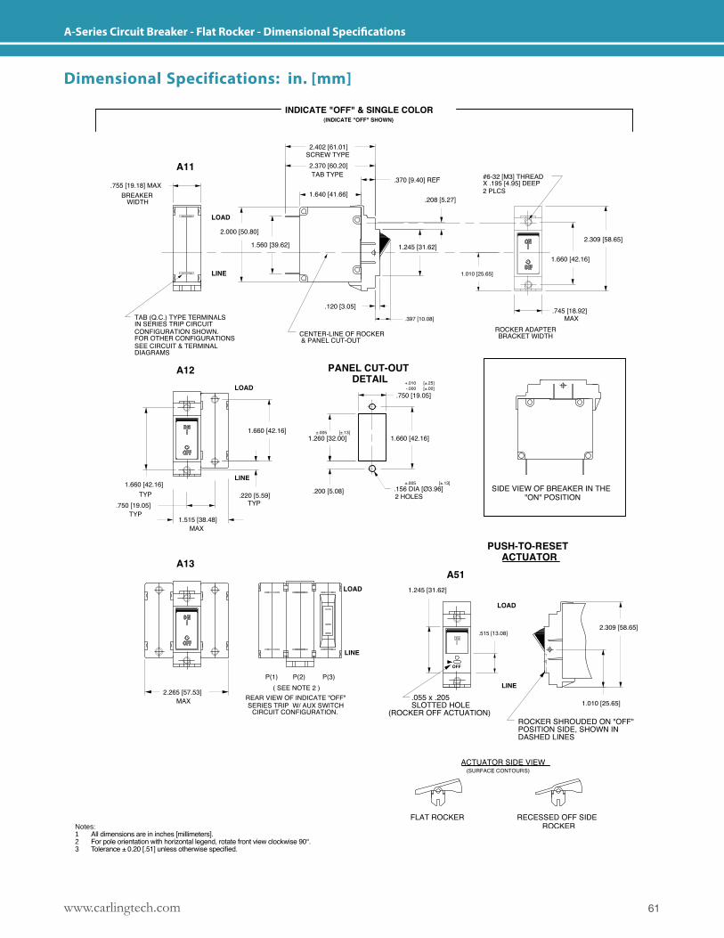
61www.carlingtech.com
A-Series Circuit Breaker - Flat Rocker - Dimensional Specifications
Notes: 1 All dimensions are in inches [millimeters].2 For pole orientation with horizontal legend, rotate front view clockwise 90°.3 Tolerance ± 0.20 [.51] unless otherwise specified.
Dimensional Specifications: in. [mm]
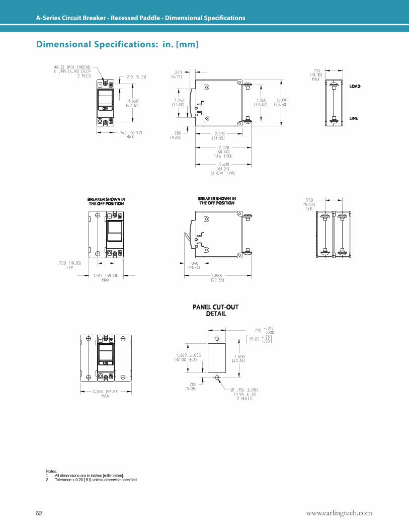
www.carlingtech.com62
A-Series Circuit Breaker - Recessed Paddle - Dimensional Specifications
Notes: 1 All dimensions are in inches [millimeters].2 Tolerance ± 0.20 [.51] unless otherwise specified
Dimensional Specifications: in. [mm]
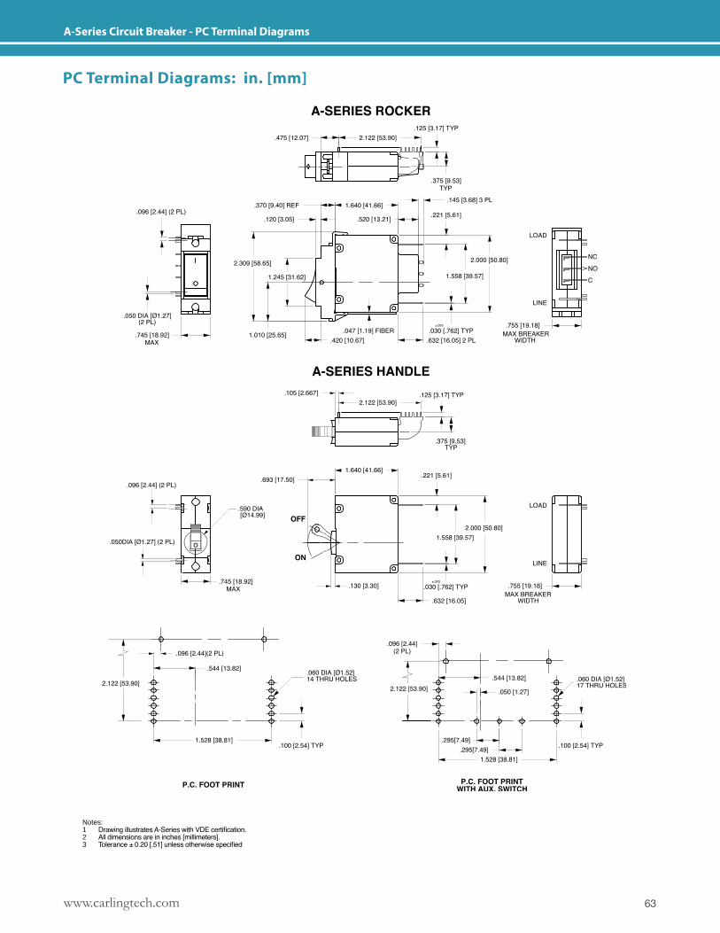
63www.carlingtech.com
A-Series Circuit Breaker - PC Terminal Diagrams
Notes: 1 Drawing illustrates A-Series with VDE certification.2 All dimensions are in inches [millimeters].3 Tolerance ± 0.20 [.51] unless otherwise specified
PC Terminal Diagrams: in. [mm]
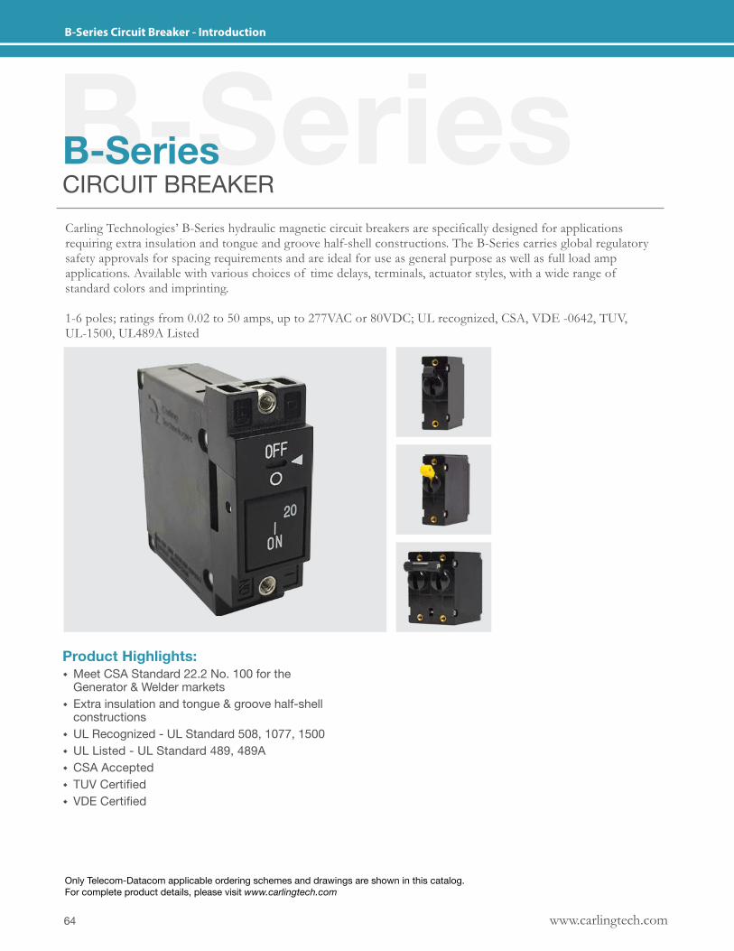
www.carlingtech.com64
B-Series Circuit Breaker - Introduction
B-SeriesB-SeriesCIRCUIT BREAKERCarling Technologies’ B-Series hydraulic magnetic circuit breakers are specifically designed for applications requiring extra insulation and tongue and groove half-shell constructions. The B-Series carries global regulatory safety approvals for spacing requirements and are ideal for use as general purpose as well as full load amp applications. Available with various choices of time delays, terminals, actuator styles, with a wide range of standard colors and imprinting.
1-6 poles; ratings from 0.02 to 50 amps, up to 277VAC or 80VDC; UL recognized, CSA, VDE -0642, TUV, UL-1500, UL489A Listed
Product Highlights: � Meet CSA Standard 22.2 No. 100 for the Generator & Welder markets
� Extra insulation and tongue & groove half-shell constructions
� UL Recognized - UL Standard 508, 1077, 1500 � UL Listed - UL Standard 489, 489A � CSA Accepted � TUV Certified � VDE Certified
Only Telecom-Datacom applicable ordering schemes and drawings are shown in this catalog. For complete product details, please visit www.carlingtech.com
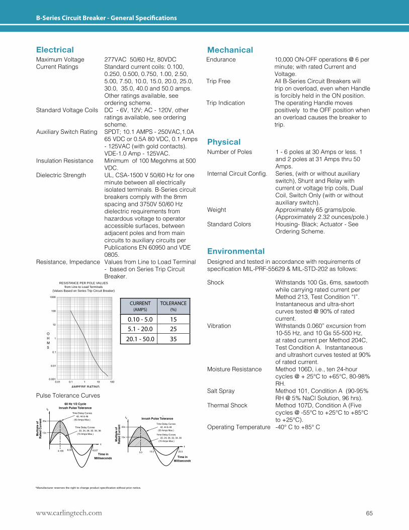
65www.carlingtech.com
B-Series Circuit Breaker - General Specifications
*Manufacturer reserves the right to change product specification without prior notice.
Mechanical
Physical
Environmental
Electrical
Pulse Tolerance Curves
Designed and tested in accordance with requirements of specificationMIL-PRF-55629&MIL-STD-202asfollows:
RESISTANCE PER POLE VALUESfrom Line to Load Terminals
(Values Based on Series Trip Circuit Breaker)
Maximum Voltage 277VAC 50/60 Hz, 80VDCCurrent Ratings Standard current coils: 0.100, 0.250, 0.500, 0.750, 1.00, 2.50, 5.00, 7.50, 10.0, 15.0, 20.0, 25.0, 30.0, 35.0, 40.0 and 50.0 amps. Other ratings available, see ordering scheme.Standard Voltage Coils DC - 6V, 12V; AC - 120V, other ratings available, see ordering scheme.Auxiliary Switch Rating SPDT; 10.1 AMPS - 250VAC,1.0A 65 VDC or 0.5A 80 VDC, 0.1 Amps - 125VAC (with gold contacts). VDE-1.0 Amp - 125VAC.Insulation Resistance Minimum of 100 Megohms at 500 VDC.Dielectric Strength UL, CSA-1500 V 50/60 Hz for one minute between all electrically isolated terminals. B-Series circuit breakers comply with the 8mm spacing and 3750V 50/60 Hz dielectric requirements from hazardous voltage to operator accessible surfaces, between adjacent poles and from main circuits to auxiliary circuits per Publications EN 60950 and VDE 0805.Resistance, Impedance Values from Line to Load Terminal - based on Series Trip Circuit Breaker.
Endurance 10,000 ON-OFF operations @ 6 per minute; with rated Current and Voltage.Trip Free All B-Series Circuit Breakers will trip on overload, even when Handle is forcibly held in the ON position.Trip Indication The operating Handle moves positively to the OFF position when an overload causes the breaker to trip.
Number of Poles 1 - 6 poles at 30 Amps or less. 1 and 2 poles at 31 Amps thru 50 Amps.InternalCircuitConfig. Series,(withorwithoutauxiliary switch), Shunt and Relay with current or voltage trip coils, Dual Coil, Switch Only (with or without auxiliary switch).Weight Approximately 65 grams/pole. (Approximately 2.32 ounces/pole.)Standard Colors Housing- Black; Actuator - See Ordering Scheme.
Shock Withstands 100 Gs, 6ms, sawtooth while carrying rated current per Method 213, Test Condition “I”. Instantaneous and ultra-short curves tested @ 90% of rated current.Vibration Withstands 0.060” excursion from 10-55 Hz, and 10 Gs 55-500 Hz, at rated current per Method 204C, Test Condition A. Instantaneous and ultrashort curves tested at 90% of rated current.Moisture Resistance Method 106D, i.e., ten 24-hour cycles @ + 25°C to +65°C, 80-98% RH.Salt Spray Method 101, Condition A (90-95% RH @ 5% NaCl Solution, 96 hrs).Thermal Shock Method 107D, Condition A (Five cycles @ -55°C to +25°C to +85°C to +25°C).Operating Temperature -40° C to +85° C
CURRENT (AMPS)
TOLERANCE (%)
0.10 - 5.0 155.1 - 20.0 25
20.1 - 50.0 35
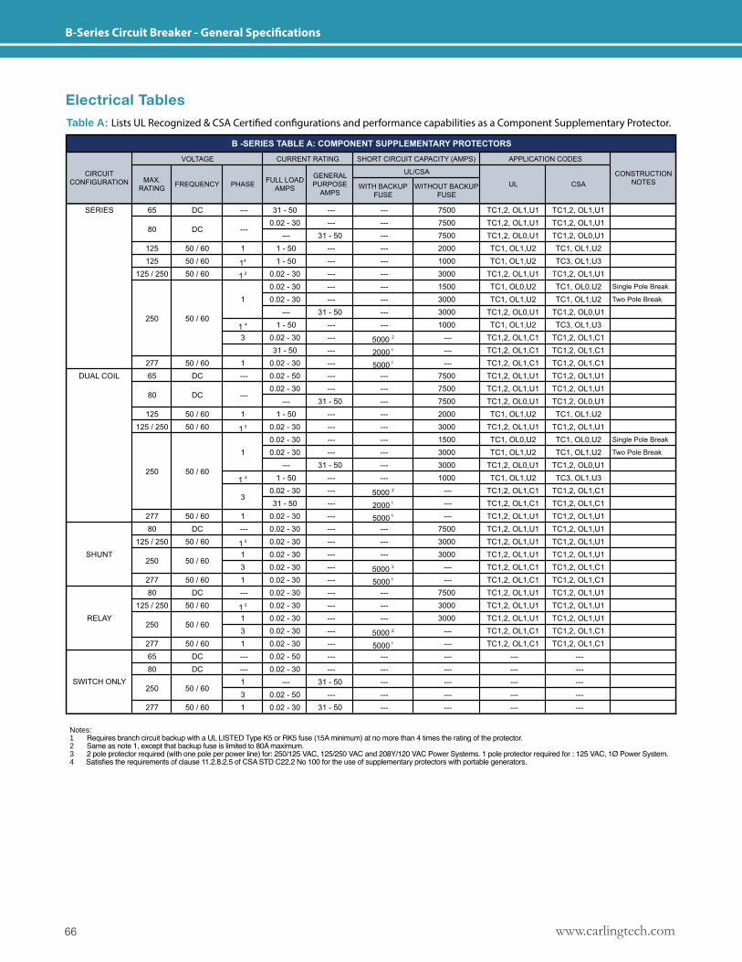
www.carlingtech.com66
B-Series Circuit Breaker - General Specifications
Electrical TablesTable A: Lists UL Recognized & CSA Certified configurations and performance capabilities as a Component Supplementary Protector.
Notes: 1 Requires branch circuit backup with a UL LISTED Type K5 or RK5 fuse (15A minimum) at no more than 4 times the rating of the protector.2 Same as note 1, except that backup fuse is limited to 80A maximum.3 2 pole protector required (with one pole per power line) for: 250/125 VAC, 125/250 VAC and 208Y/120 VAC Power Systems. 1 pole protector required for : 125 VAC, 1Ø Power System.4 Satisfies the requirements of clause 11.2.8.2.5 of CSA STD C22.2 No 100 for the use of supplementary protectors with portable generators.
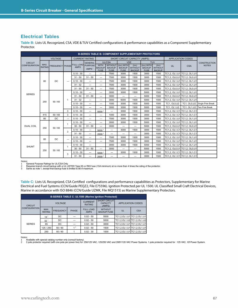
67www.carlingtech.com
B-Series Circuit Breaker - General Specifications
Electrical TablesTable B: Lists UL Recognized, CSA, VDE & TUV Certified configurations & performance capabilities as a Component Supplementary Protector.
Table C: Lists UL Recognized, CSA Certified configurations and performance capabilities as Protectors, Supplementary for Marine Electrical and Fuel Systems (CCN/Guide PEQZ2, File E75596). Ignition Protected per UL 1500. UL Classified Small Craft Electrical Devices, Marine in accordance with ISO 8846 (CCN/Guide UZMK, File MQ1515) as Marine Supplementary Protectors.
Notes: 1 General Purpose Ratings for UL/CSA Only.2 Requires branch circuit backup with a UL LISTED Type K5 or RK5 fuse (15A minimum) at no more than 4 times the rating of the protector.3 Same as note 1, except that backup fuse is limited to 80 A maximum.
Notes: 1 Available with special catalog number only (consult factory).2 2 pole protector required (with one pole per power line) for: 250/125 VAC, 125/250 VAC and 208Y/120 VAC Power Systems. 1 pole protector required for : 125 VAC, 1Ø Power System.
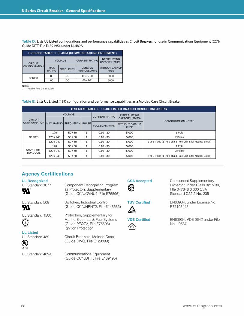
www.carlingtech.com68
B-Series Circuit Breaker - General Specifications
Table D: Lists UL Listed configurations and performance capabilities as Circuit Breakers for use in Communications Equipment (CCN/Guide DITT, File E189195), under UL489A
Table E: Lists UL Listed (489) configuration and performance capabilities as a Molded Case Circuit Breaker.
120 50 / 60 1 0.10 - 30 5,000 1 Pole
SERIES 120 / 240 50 / 60 1 0.10 - 30 5,000 2 Poles
120 / 240 50 / 60 1 0.10 - 30 5,000 2 or 3 Poles (1 Pole of a 3 Pole Unit is for Neutral Break)
120 50 / 60 1 0.10 - 30 5,000 1 Pole
120 / 240 50 / 60 1 0.10 - 30 5,000 2 Poles
120 / 240 50 / 60 1 0.10 - 30 5,000 2 or 3 Poles (1 Pole of a 3 Pole Unit is for Neutral Break)
SHUNT TRIP DUAL COIL
B SERIES TABLE E : UL489 LISTED BRANCH CIRCUIT BREAKERS
VOLTAGE INTERRUPTING CAPACITY (AMPS)
CONSTRUCTION NOTESMAX. RATING FREQUENCY PHASE WITHOUT BACKUP
FUSE
CIRCUIT CONFIGURATION
FULL LOAD AMPS
CURRENT RATING
Notes: 1 Parallel Pole Construction
Agency CertificationsUL RecognizedUL Standard 1077
UL Standard 508
UL Standard 1500
UL ListedUL Standard 489
UL Standard 489A
CSA Accepted
TUV Certified
VDE Certified
Component Recognition Program as Protectors Supplementary (Guide CCN/QVNU2, File E75596)
Switches, Industrial Control (Guide CCN/NRNT2, File E148683)
Protectors, Supplementary for Marine Electrical & Fuel Systems (Guide PEQZ2, File E75596) Ignition Protection
Circuit Breakers, Molded Case, (Guide DIVQ, File E129899)
Communications Equipment (Guide CCN/DITT, File E189195)
Component Supplementary Protector under Class 3215 30, FIle 047848 0 000 CSA Standard C22.2 No. 235
EN60934, under License No. R72103448
EN60934, VDE 0642 under File No. 10537
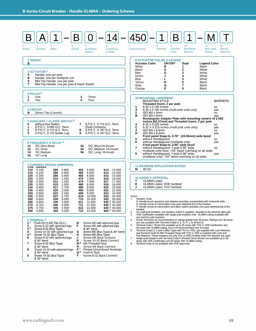
69www.carlingtech.com
B-Series Circuit Breaker - Handle UL489A – Ordering Scheme
1Series
2Actuator
3Poles
5Aux/Alarm Switch
6Frequency& Delay
7Current Rating
8Terminal
9ActuatorColor
10Mounting/Barriers
11Max. Appl. Rating
12AgencyApproval
4 Circuit
B A B 1 11 0 B M T14 450
1 SERIESB
2 ACTUATOR 1A Handle, one per poleB Handle, one per multipole unitS Mid-Trip Handle, one per poleT Mid-Trip Handle, one per pole & Alarm Switch
3 POLES 2 1 One2 Two
3 Three4 Four
6 FREQUENCY & DELAY 411 DC Ultra Short12 DC Short14 DC Medium16 DC Long
52 DC, Short,Hi-Inrush 54 DC, Medium, Hi-Inrush 56 DC, Long, Hi-Inrush
12 AGENCY APPROVALT UL489A ListedK UL489A Listed, VDE CertifiedJ UL489A Listed, TUV Certified
11 MAXIMUM APPLICATION RATINGM 80 DC
9 ACTUATOR COLOR & LEGENDActuator Color ON-OFF Dual Legend ColorWhite B 1 BlackBlack D 2 WhiteRed G 3 WhiteGreen J 4 WhiteBlue L 5 WhiteYellow N 6 BlackGray Q 7 BlackOrange S 8 Black
Notes: 1 Actuator Code: A: Handle tie pin spacer(s) and retainers provided unassembled with multi-pole units. S: Handle moves to mid-position only upon electrical trip of the breaker. T: Handle moves to mid-position and alarm switch activates only upon electrical trip of the breaker.2 On multi-pole breakers, one auxiliary switch is supplied, mounted in the extreme right pole.3 VDE Certification available with single pole breakers only. UL489A Listing available with one and two pole breakers.4 Screw Terminals are recommended on ratings greater than 20 amps. Ratings over 30 amps are only available with Terminal Codes 5, 9, G, H, J, K, M and Q.5 Terminal Code 1 (Push-On) available up to 25 amps with TUV or VDE Certification and 30 amps with UL489A Listing, but is not recommended over 20 amps.6 Terminal Codes 3, 5 and H (Bus Type) with TUV or VDE, are supplied with Lock Washers, and Terminal Code M (M6 Threaded Stud) with TUV or VDE is supplied with Lock and Flat Washers. These breakers are only TUV or VDE Certified when the washers are used. 7 Single pole breakers with Terminal Code P (Printed Circuit Board) are available up to 30 amps with VDE Certification and 50 amps with UL489A Listing. 8 Terminal Code Q not available with VDE approvals.
4 CIRCUITB Series Trip (Current)
5 AUXILIARY / ALARM SWITCH 2 0 without Aux Switch 7 S.P.S.T., 0.110 Q.C. Term.1 S.P.D.T., 0.093 Q.C. Term. (Gold Contacts)2 S.P.D.T., 0.110 Q.C. Term. 8 S.P.S.T., 0.187 Q.C. Term.3 S.P.D.T., 0.110 Solder Lug 9 S.P.D.T., 0.187 Q.C. Term.
7 CURRENT RATING (AMPERES)CODE AMPERES 210 0.100215 0.150220 0.200225 0.250230 0.300235 0.350240 0.400245 0.450250 0.500255 0.550260 0.600265 0.650270 0.700275 0.750280 0.800
285 0.850290 0.900295 0.950410 1.000512 1.250415 1.500517 1.750420 2.000522 2.250527 2.750430 3.000435 3.500440 4.000445 4.500450 5.000
455 5.500460 6.000465 6.500470 7.000475 7.500480 8.000485 8.500490 9.000495 9.500610 10.000710 10.500611 11.000711 11.500612 12.000712 12.500
613 13.000614 14.000615 15.000616 16.000617 17.000618 18.000620 20.000622 22.000624 24.000625 25.000630 30.000635 3 35.000640 3 40.000645 3 45.000650 3 50.000
8 TERMINAL 4
1 5 Push-On 0.250 Tab (Q.C.) B Screw M5 with upturned lugs2 Screw 8-32 with upturned lugs F Screw M5 with upturned lugs3 6 Screw 8-32 (Bus Type) & 30° bend4 Screw 10-32 with upturned lugs G Screw M5 (Bus Type) & 30° bend 5 6 Screw 10-32 (Bus Type) H Screw M5 (Bus Type)6 Screw 8-32 with upturned lugs J Screw M5 Back Connect & 30° bend K Screw 10-32 Back Connect7 Screw 8-32 (Bus Type) M 6 M6 Threaded Stud & 30° bend N Screw M4 Back Connect8 Screw 10-32 with upturned lugs P 7 Printed Circuit Board Terminals & 30° bend Q 8 Push-In Stud9 Screw 10-32 (Bus Type) Y Screw 8-32 Back Connect & 30° bend
10 MOUNTING / BARRIERS MOUNTING STYLE BARRIERS Threaded Insert, 2 per pole1 6-32 x 0.195 inches noA 6-32 x 0.195 inches (multi-pole units only) yes 2 ISO M3 x 5mm no B ISO M3 x 5mm yes Rectangular Adapter Plate with mounting centers of 2.062 inches [52.37mm] and Threaded insert, 2 per pole3 6-32 x 0.225 inches no C 6-32 X 0.225 inches (multi-pole units only) yes4 ISO M3 x 6.5mm no D ISO M3 x 6.5mm yes Front panel Snap-In, 0.75” [19.05mm] wide bezel 5 without Handleguard no 6 without Handleguard (multipole only) yes Front panel Snap-In, 0.96” wide bezel 7 without Handleguard, 1-pole 0.96” wide; no multipole units have .105” bezel overhang on all sides 8 without Handleguard, 1-pole 0.96” wide; yes (multipole only) .105” bezel overhang on all sides
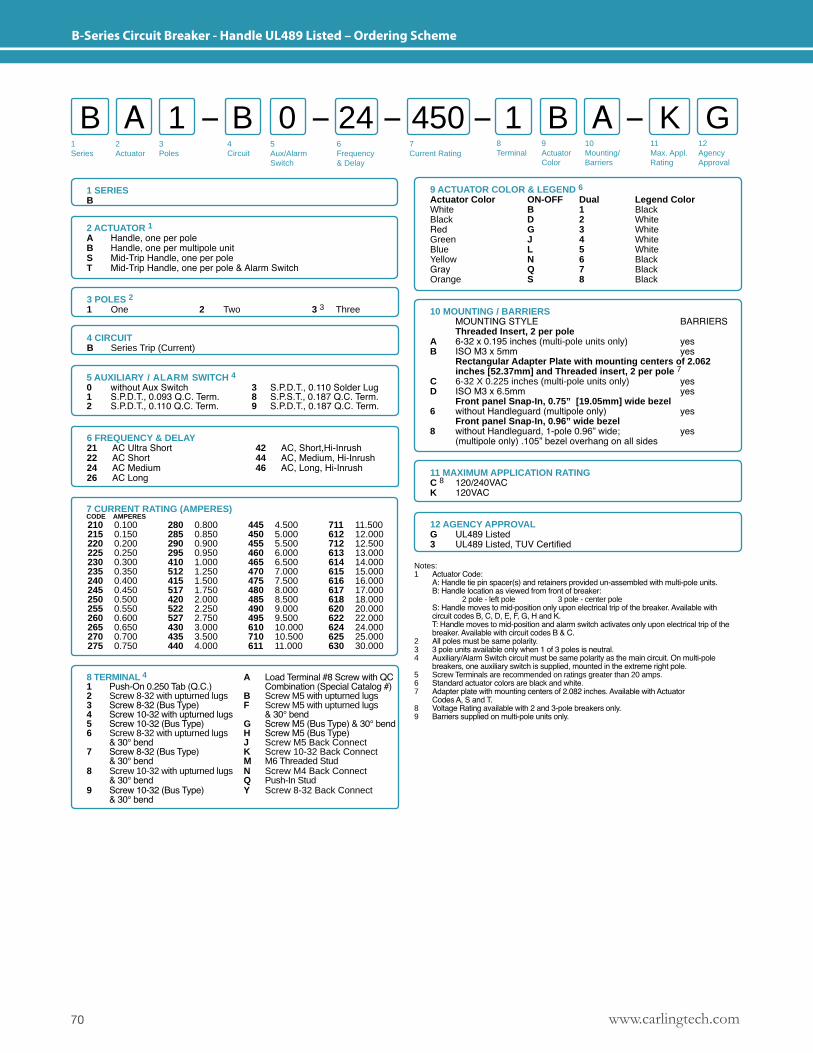
www.carlingtech.com70
B-Series Circuit Breaker - Handle UL489 Listed – Ordering Scheme
1 SERIESB
2 ACTUATOR 1A Handle, one per poleB Handle, one per multipole unitS Mid-Trip Handle, one per poleT Mid-Trip Handle, one per pole & Alarm Switch
1Series
2Actuator
3Poles
5Aux/Alarm Switch
6Frequency& Delay
7Current Rating
8Terminal
9ActuatorColor
10Mounting/Barriers
11Max. Appl. Rating
12AgencyApproval
4 Circuit
B A B 1 A1 0 B K G24 450
3 POLES 2 1 One 2 Two 3 3 Three
6 FREQUENCY & DELAY21 AC Ultra Short22 AC Short24 AC Medium26 AC Long
42 AC, Short,Hi-Inrush 44 AC, Medium, Hi-Inrush 46 AC, Long, Hi-Inrush
12 AGENCY APPROVALG UL489 Listed3 UL489 Listed, TUV Certified
11 MAXIMUM APPLICATION RATINGC 8 120/240VAC K 120VAC
9 ACTUATOR COLOR & LEGEND 6Actuator Color ON-OFF Dual Legend ColorWhite B 1 BlackBlack D 2 WhiteRed G 3 WhiteGreen J 4 WhiteBlue L 5 WhiteYellow N 6 BlackGray Q 7 BlackOrange S 8 Black
Notes: 1 Actuator Code: A: Handle tie pin spacer(s) and retainers provided un-assembled with multi-pole units. B: Handle location as viewed from front of breaker: 2 pole - left pole 3 pole - center pole S: Handle moves to mid-position only upon electrical trip of the breaker. Available with circuit codes B, C, D, E, F, G, H and K. T: Handle moves to mid-position and alarm switch activates only upon electrical trip of the breaker. Available with circuit codes B & C.2 All poles must be same polarity.3 3 pole units available only when 1 of 3 poles is neutral.4 Auxiliary/Alarm Switch circuit must be same polarity as the main circuit. On multi-pole breakers, one auxiliary switch is supplied, mounted in the extreme right pole.5 Screw Terminals are recommended on ratings greater than 20 amps. 6 Standard actuator colors are black and white.7 Adapter plate with mounting centers of 2.082 inches. Available with Actuator Codes A, S and T.8 Voltage Rating available with 2 and 3-pole breakers only.9 Barriers supplied on multi-pole units only.
4 CIRCUITB Series Trip (Current)
10 MOUNTING / BARRIERS MOUNTING STYLE BARRIERS Threaded Insert, 2 per poleA 6-32 x 0.195 inches (multi-pole units only) yes B ISO M3 x 5mm yes Rectangular Adapter Plate with mounting centers of 2.062 inches [52.37mm] and Threaded insert, 2 per pole 7C 6-32 X 0.225 inches (multi-pole units only) yesD ISO M3 x 6.5mm yes Front panel Snap-In, 0.75” [19.05mm] wide bezel 6 without Handleguard (multipole only) yes Front panel Snap-In, 0.96” wide bezel 8 without Handleguard, 1-pole 0.96” wide; yes (multipole only) .105” bezel overhang on all sides
5 AUXILIARY / ALARM SWITCH 4 0 without Aux Switch 3 S.P.D.T., 0.110 Solder Lug1 S.P.D.T., 0.093 Q.C. Term. 8 S.P.S.T., 0.187 Q.C. Term.2 S.P.D.T., 0.110 Q.C. Term. 9 S.P.D.T., 0.187 Q.C. Term.
7 CURRENT RATING (AMPERES)CODE AMPERES 210 0.100215 0.150220 0.200225 0.250230 0.300235 0.350240 0.400245 0.450250 0.500255 0.550260 0.600265 0.650270 0.700275 0.750
280 0.800285 0.850290 0.900295 0.950410 1.000512 1.250415 1.500517 1.750420 2.000522 2.250527 2.750430 3.000435 3.500440 4.000
445 4.500450 5.000455 5.500460 6.000465 6.500470 7.000475 7.500480 8.000485 8.500490 9.000495 9.500610 10.000710 10.500611 11.000
711 11.500612 12.000712 12.500613 13.000614 14.000615 15.000616 16.000617 17.000618 18.000620 20.000622 22.000624 24.000625 25.000630 30.000
8 TERMINAL 4 A Load Terminal #8 Screw with QC1 Push-On 0.250 Tab (Q.C.) Combination (Special Catalog #)2 Screw 8-32 with upturned lugs B Screw M5 with upturned lugs3 Screw 8-32 (Bus Type) F Screw M5 with upturned lugs4 Screw 10-32 with upturned lugs & 30° bend5 Screw 10-32 (Bus Type) G Screw M5 (Bus Type) & 30° bend6 Screw 8-32 with upturned lugs H Screw M5 (Bus Type) & 30° bend J Screw M5 Back Connect7 Screw 8-32 (Bus Type) K Screw 10-32 Back Connect & 30° bend M M6 Threaded Stud8 Screw 10-32 with upturned lugs N Screw M4 Back Connect & 30° bend Q Push-In Stud9 Screw 10-32 (Bus Type) Y Screw 8-32 Back Connect & 30° bend
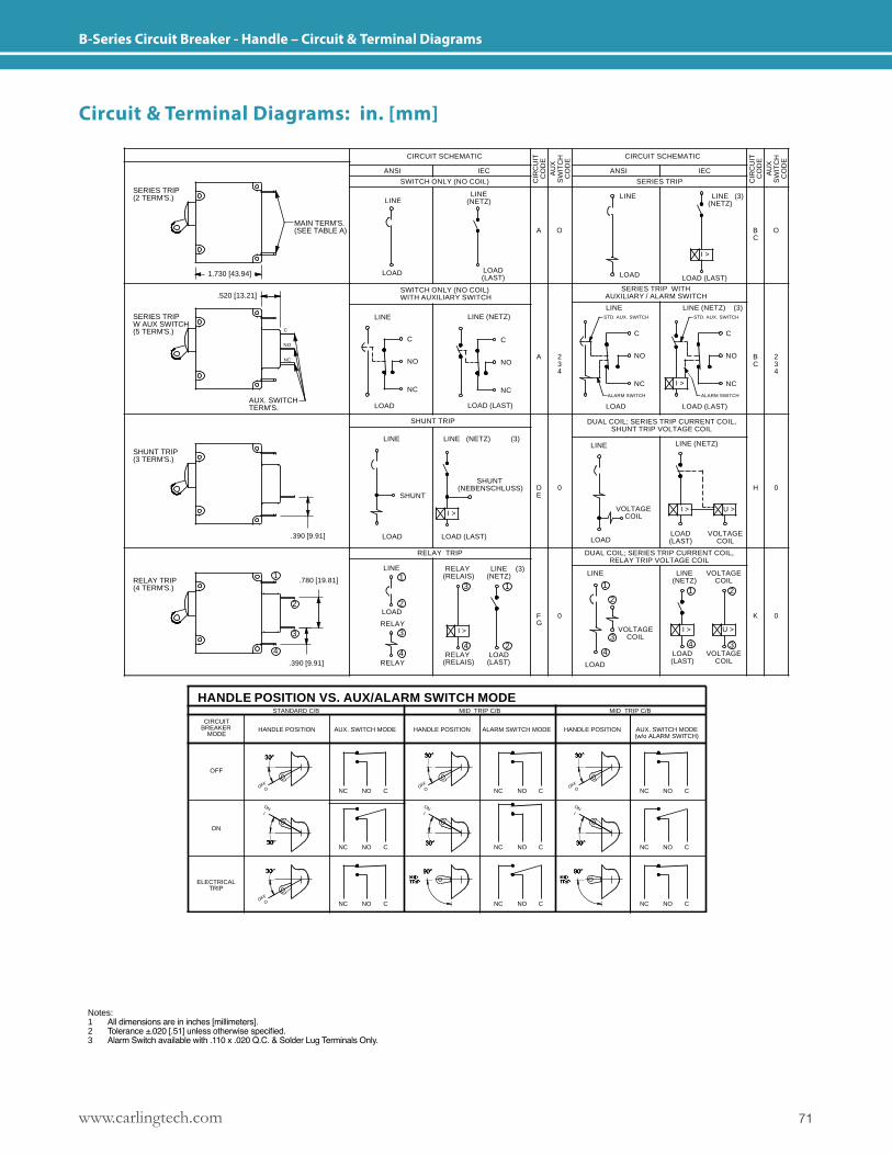
71www.carlingtech.com
B-Series Circuit Breaker - Handle – Circuit & Terminal Diagrams
A
A
DE
FG
CIR
CU
ITC
OD
E
C
C
ALARM SWITCH MODE
C
HANDLE POSITION VS. AUX/ALARM SWITCH MODE
RELAY TRIP(4 TERM'S.)
NOO
30°
NC C O NONC
NO
NO
ON
NC
ELECTRICALTRIP
30°
OOFF
I
ON
30°NC
C NONC
90°MID TRIP
30°NCC
ONI
NO
AUX. SWITCH MODECIRCUIT
BREAKERMODE
OFF
OFF
1
4
3
2
HANDLE POSITION
STANDARD C/B
.390 [9.91]
.780 [19.81]
30°
OFF
244
MID TRIP C/B
HANDLE POSITION
31
1
2
3
RELAY(RELAIS)
I >
LOAD(LAST)
LOAD
RELAY
RELAY
RELAY(RELAIS)
(3)LINE(NETZ)
LINE
SERIES TRIP W AUX SWITCH(5 TERM'S.)
SERIES TRIP (2 TERM'S.)
SHUNT TRIP(3 TERM'S.)
C C
.390 [9.91]
NO
NC
AUX. SWITCHTERM'S.
RELAY TRIP
LOAD (LAST)LOAD
I >
LOAD (LAST)
SHUNT(NEBENSCHLUSS)
LINE (NETZ) (3)
NC
LINE
LOAD
NO
SHUNT TRIP
SHUNT
NC
NO
.520 [13.21]
C
1.730 [43.94]
MAIN TERM'S.(SEE TABLE A)
SWITCH ONLY (NO COIL)WITH AUXILIARY SWITCH
LINE (NETZ)LINE
LOAD(LAST)
IEC
LINE(NETZ)
LOAD
ANSI
LINE
SWITCH ONLY (NO COIL)
CIRCUIT SCHEMATIC
O CNC NO
MID TRIP
90°
30°
ONI
CNONC
CNONC
VOLTAGECOIL
VOLTAGECOIL
30°
AUX. SWITCH MODE(w/o ALARM SWITCH)
OFF
1
4
3
2
4
1
MID TRIP C/B
HANDLE POSITION
LINE(NETZ)
VOLTAGECOIL
LOAD(LAST)
I >
0
LINE
LOAD
K
U >
0
2
3
DUAL COIL; SERIES TRIP CURRENT COIL,RELAY TRIP VOLTAGE COIL
VOLTAGECOIL
LINE (NETZ)
LOAD (LAST)
ALARM SWITCH
DUAL COIL; SERIES TRIP CURRENT COIL,SHUNT TRIP VOLTAGE COIL
VOLTAGECOIL
I >
LOAD(LAST)LOAD
NO
NC I >
LOAD
ALARM SWITCH
234
0
LINE
U >
NO BC
H
NC
234
0
LOAD (LAST)
LINE (3)(NETZ)
LINE (NETZ) (3)STD. AUX. SWITCH
SERIES TRIP WITHAUXILIARY / ALARM SWITCH
CIRCUIT SCHEMATIC
AU
XS
WIT
CH
CO
DE
LINESTD. AUX. SWITCH
C
SERIES TRIP
IEC
LINE
LOAD
ANSI
I >
O
C
BC
O
AU
XS
WIT
CH
CO
DE
CIR
CU
ITC
OD
E
Circuit & Terminal Diagrams: in. [mm]
Notes: 1 All dimensions are in inches [millimeters].2 Tolerance ±.020 [.51] unless otherwise specified.3 Alarm Switch available with .110 x .020 Q.C. & Solder Lug Terminals Only.

www.carlingtech.com72
B-Series Circuit Breaker - Handle – Circuit & Terminal Diagrams
2 PLCS30°
12-15 IN-LBS [1.4-1.7 NM]15-20 IN-LBS[1.7-2.3 NM]
1.000 [25.40]
.392 [9.97]
TORQUE
.154 [3.91] DIA
7-9 IN-LBS [0.8-1.0 NM]
* AVAILABLE ON SERIES TRIP AND SWITCH ONLY CIRCUITS.WHEN CALLED FOR ON MULTI-POLE UNITS, ONLY ONE AUX. SWITCH IS NORMALLY SUPPLIED, AS SHOWN IN MULTI-POLE IDENTIFICATION SCHEME.
TABLE ATIGHTENING TORQUE
SPECIFICATIONS
1.560 [39.62]
DEPTH BEHIND PANEL
CENTERLINE OF PUSH-INSTUD CONTACT AREA
SCREW TERMINALWITH 30° BEND
BARRIER FORUL-489 MULTI-POLE
BREAKERS
BARRIER FORUL-RECOGNIZED MULTI-POLE
BREAKERS
OFFO
ONI
MIDTRIP 1.560 [39.62] TYP
.220 [5.59] TYP
TYP.032 [.81]
LOAD(LAST)
SEE TABLE-BDEPTH BEHIND PANEL
LINE(NETZ)
BACK CONNECTSCREW TERMINALWITH RETAINER
1.250 [31.75]
BACK CONNECTSCREW TERMINAL
PUSH-INSTUD
1.936[49.17]
M6 STUD
1.350 [34.29]
.393 [9.96] REF
.392[9.96]
.093DIA [.76]
.087 [2.20]
.287 [7.29]
1.313 [33.35]
TAB (Q.C.)
.051 DIA[Ø1.29]
AUXILIARY SWITCH TERMINAL DETAIL
TERMINAL DIMENSIONAL DETAIL & RATING
.161 DIA [Ø 4.10]
PUSH-IN STUD
MATING HOLE
2.230 [56.64] TYP
.875 [22.23] REF
LINE
LOAD
.069[1.75] DIA
.360[9.14]
TAB (Q.C.)
30 AMP
.250[6.35].375[9.53].375[9.53]
#8-32 30 AMP#10-32 30 AMP
M5 30 AMPM4 30 AMP
+.002 [+.05]-.000 [-.00]
UPTURN LUG BUS#8-32 30 AMP
#10-32 50 AMP
.392[9.96]
.110 [2.80] .110 [2.80]
.070 DIA [Ø1.80]
LINE
LOAD
2.000 [50.80]
.126 [3.20]
.520 [13.21]
SOLDER TYPE
TERMINAL DESCRIPTION
SHUNT, RELAY &
DUAL COIL
AUX. SWITCH*
MAIN
SCREW #8-32 W/UPTURNED LUGS
TAB (Q.C.) .110 x .020
TAB (Q.C.)
SCREW TYPE
SOLDER TYPE
TAB (Q.C.)
THREAD SIZE#6-32 & M3 MOUNTINGHARDWARE#8-32 & M4 THREADTERMINAL SCREW#10-32 & M5 THREADTERMINAL SCREW
TABLE B
M6 STUD50 AMP
.250[6.35] .437 [11.10]
#8-32 30 AMP#10-32 50 AMP
M5 50 AMPM4 30 AMP
QC SOLDER LUG30 AMP
BACK CONNECT
.205 [5.21].344[8.74]
.405[10.29]
.750 [19.05]
.100 [2.54]
PUSH-IN STUD50 AMP
.750[19.05]
TYP
2.612 [66.35]
2.644 [67.16]
2.537 [64.44]
2.348 [59.64]
2.090 [53.09]
2.122 [53.90]
Circuit & Terminal Diagrams: in. [mm]
Notes: 1 All dimensions are in inches [millimeters].2 Tolerance ±.020 [.51] unless otherwise specified.
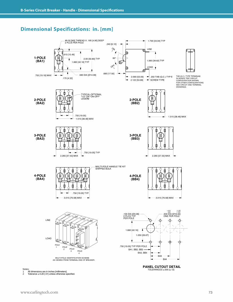
73www.carlingtech.com
B-Series Circuit Breaker - Handle - Dimensional Specifications
Dimensional Specifications: in. [mm]
Notes: 1 All dimensions are in inches [millimeters].2 Tolerance ± 0.20 [.51] unless otherwise specified.
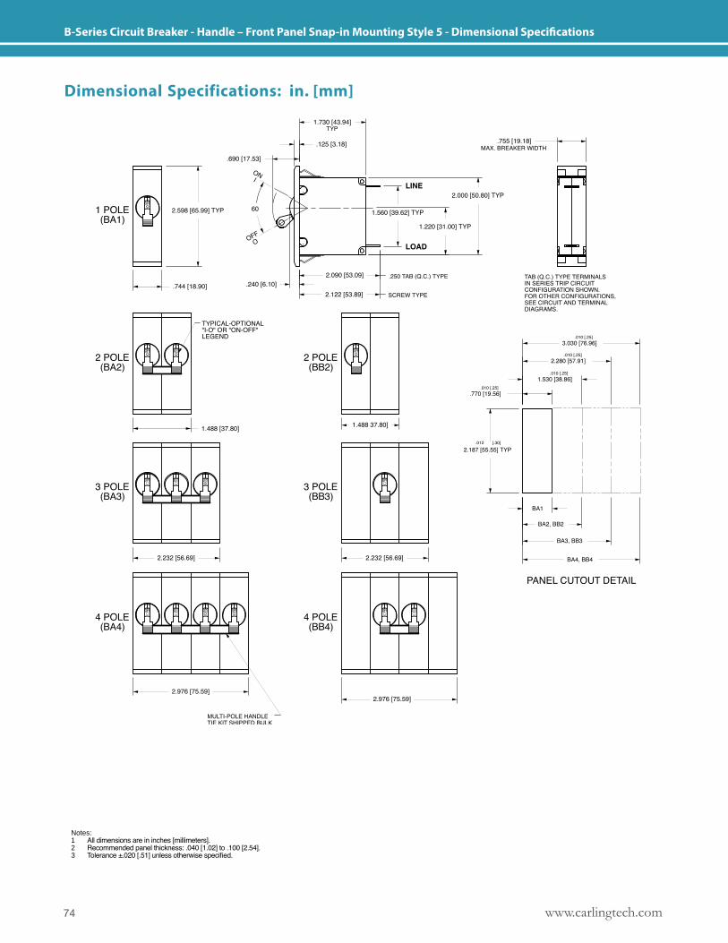
www.carlingtech.com74
B-Series Circuit Breaker - Handle – Front Panel Snap-in Mounting Style 5 - Dimensional Specifications
Dimensional Specifications: in. [mm]
Notes: 1 All dimensions are in inches [millimeters].2 Recommended panel thickness: .040 [1.02] to .100 [2.54].3 Tolerance ±.020 [.51] unless otherwise specified.
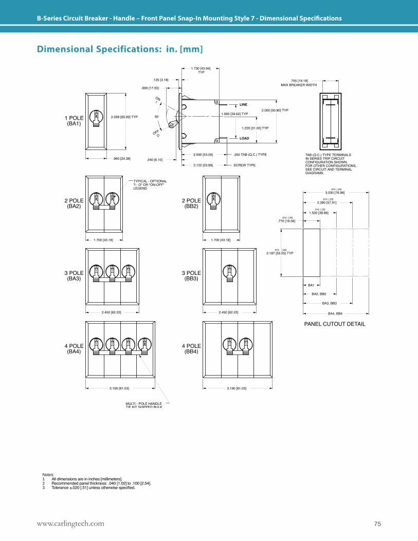
75www.carlingtech.com
B-Series Circuit Breaker - Handle – Front Panel Snap-In Mounting Style 7 - Dimensional Specifications
Dimensional Specifications: in. [mm]
Notes: 1 All dimensions are in inches [millimeters].2 Recommended panel thickness: .040 [1.02] to .100 [2.54].3 Tolerance ±.020 [.51] unless otherwise specified.
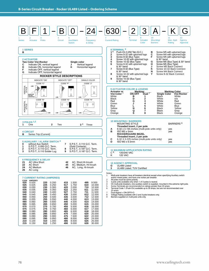
www.carlingtech.com76
B-Series Circuit Breaker - Rocker UL489 Listed – Ordering Scheme
1Series
2Actuator
3Poles
5Aux/Alarm Switch
6Frequency& Delay
7Current Rating
8Terminal
9ActuatorColor
10Mounting/Barriers
11Max. Appl. Rating
12AgencyApproval
4 Circuit
B F B 2 A1 0 3 K G24 630
1 SERIESB
6 FREQUENCY & DELAY21 AC Ultra Short22 AC Short24 AC Medium26 AC Long
42 AC, Short,Hi-Inrush 44 AC, Medium, Hi-Inrush 46 AC, Long, Hi-Inrush
12 AGENCY APPROVALG UL489 Listed3 UL489 Listed, TUV Certified
11 MAXIMUM APPLICATION RATINGC 8 120/240 VACK 120 VAC
Notes: 1 Multi-pole breakers have all breakers identical except when specifying Auxiliary switch and/or mixed poles, and have one rocker per breaker.2 All poles must be same polarity.3 3 pole units available only when 1 of 3 poles is neutral.4 On multi-pole breakers, one auxiliary switch is supplied, mounted in the extreme right pole.5 Screw Terminals are recommended on ratings greater than 20 amps. 6 Terminal Code 1 (Push-On) available up to 30 amps, but are not recommended over 20 amps.7 Dual legend = ON-OFF/I-O8 Voltage Rating available with 2 and 3-pole breakers only.9 Barriers supplied on multi-pole units only.
4 CIRCUITB Series Trip (Current)
10 MOUNTING / BARRIERS MOUNTING STYLE BARRIERS 9 Threaded Insert, 2 per poleA 6-32 x 0.195 inches (multi-pole units only) yes B ISO M3 x 5mm yes ROCKERGUARD BEZEL Threaded Insert, 2 per poleC 6-32 X 0.225 inches (multi-pole units only) yesD ISO M3 x 6.5mm yes
2 ACTUATORTwo Color Visi-Rocker Single colorC Indicate ON, vertical legend J Vertical legendD Indicate ON, horizontal legend K Horizontal legendF Indicate OFF, vertical legendG Indicate OFF, horizontal legend
3 POLES 1,2 1 One 2 Two 3 3 Three
7 CURRENT RATING (AMPERES)CODE AMPERES 020 0.020025 0.025030 0.030035 0.035040 0.040045 0.045050 0.050055 0.055060 0.060065 0.065070 0.070075 0.075080 0.080085 0.085090 0.090095 0.095210 0.100215 0.150
220 0.200225 0.250230 0.300235 0.350240 0.400245 0.450250 0.500255 0.550260 0.600265 0.650270 0.700275 0.750280 0.800285 0.850290 0.900295 0.950410 1.000512 1.250
415 1.500517 1.750420 2.000522 2.250527 2.750430 3.000435 3.500440 4.000445 4.500450 5.000455 5.500460 6.000465 6.500470 7.000475 7.500480 8.000485 8.500490 9.000
495 9.500610 10.000710 10.500611 11.000711 11.500612 12.000712 12.500613 13.000614 14.000615 15.000616 16.000617 17.000618 18.000620 20.000622 22.000624 24.000625 25.000630 30.000
9 ACTUATOR COLOR & LEGEND Actuator or Marking: Marking Color Visi-Color 7 ON-OFF Dual 7 Single Color Visi-Rocker White B 1 Black WhiteBlack D 2 White n/aRed G 3 White RedGreen J 4 White GreenBlue L 5 White BlueYellow N 6 Black YellowGray Q 7 Black GrayOrange S 8 Black Orange
5 AUXILIARY / ALARM SWITCH 4 0 without Aux Switch 7 S.P.S.T., 0.110 Q.C. Term.1 S.P.D.T., 0.093 Q.C. Term. (Gold Contacts)2 S.P.D.T., 0.110 Q.C. Term. 8 S.P.S.T., 0.187 Q.C. Term.3 S.P.D.T., 0.110 Solder Lug 9 S.P.D.T., 0.187 Q.C. Term.
8 TERMINAL 5
1 6 Push-On 0.250 Tab (Q.C.) B Screw M5 with upturned lugs2 Screw 8-32 with upturned lugs C Screw M4 with upturned lugs3 Screw 8-32 (Bus Type) F Screw M5 with upturned lugs4 Screw 10-32 with upturned lugs & 30° bend5 Screw 10-32 (Bus Type) G Screw M5 (Bus Type) & 30° bend6 Screw 8-32 with upturned lugs H Screw M5 (Bus Type) & 30° bend J Screw M5 Back Connect7 Screw 8-32 (Bus Type) K Screw 10-32 Back Connect & 30° bend N Screw M4 Back Connect 8 Screw 10-32 with upturned lugs Y Screw 8-32 Back Connect & 30° bend 9 Screw 10-32 (Bus Type) & 30° bend
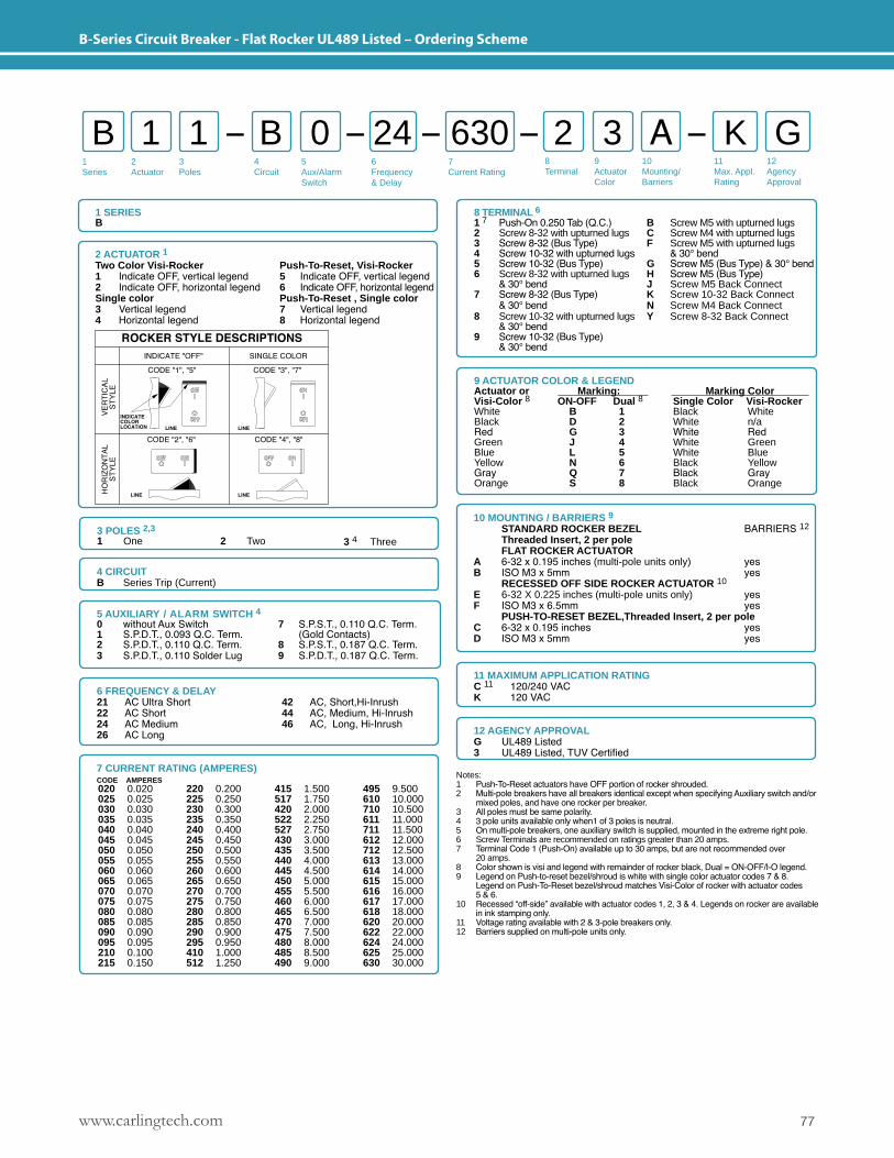
77www.carlingtech.com
B-Series Circuit Breaker - Flat Rocker UL489 Listed – Ordering Scheme
1Series
2Actuator
3Poles
5Aux/Alarm Switch
6Frequency& Delay
7Current Rating
8Terminal
9ActuatorColor
10Mounting/Barriers
11Max. Appl. Rating
12AgencyApproval
4 Circuit
B 1 B 2 A1 0 3 K G24 630
1 SERIESB
10 MOUNTING / BARRIERS 9 STANDARD ROCKER BEZEL BARRIERS 12
Threaded Insert, 2 per pole FLAT ROCKER ACTUATORA 6-32 x 0.195 inches (multi-pole units only) yes B ISO M3 x 5mm yes RECESSED OFF SIDE ROCKER ACTUATOR 10
E 6-32 X 0.225 inches (multi-pole units only) yesF ISO M3 x 6.5mm yes PUSH-TO-RESET BEZEL,Threaded Insert, 2 per pole C 6-32 x 0.195 inches yes D ISO M3 x 5mm yes
2 ACTUATOR 1Two Color Visi-Rocker Push-To-Reset, Visi-Rocker 1 Indicate OFF, vertical legend 5 Indicate OFF, vertical legend2 Indicate OFF, horizontal legend 6 Indicate OFF, horizontal legendSingle color Push-To-Reset , Single color3 Vertical legend 7 Vertical legend4 Horizontal legend 8 Horizontal legend
6 FREQUENCY & DELAY21 AC Ultra Short22 AC Short24 AC Medium26 AC Long
42 AC, Short,Hi-Inrush 44 AC, Medium, Hi-Inrush 46 AC, Long, Hi-Inrush
12 AGENCY APPROVALG UL489 Listed3 UL489 Listed, TUV Certified
11 MAXIMUM APPLICATION RATINGC 11 120/240 VACK 120 VAC
Notes: 1 Push-To-Reset actuators have OFF portion of rocker shrouded.2 Multi-pole breakers have all breakers identical except when specifying Auxiliary switch and/or mixed poles, and have one rocker per breaker.3 All poles must be same polarity.4 3 pole units available only when1 of 3 poles is neutral.5 On multi-pole breakers, one auxiliary switch is supplied, mounted in the extreme right pole.6 Screw Terminals are recommended on ratings greater than 20 amps. 7 Terminal Code 1 (Push-On) available up to 30 amps, but are not recommended over 20 amps.8 Color shown is visi and legend with remainder of rocker black, Dual = ON-OFF/I-O legend.9 Legend on Push-to-reset bezel/shroud is white with single color actuator codes 7 & 8. Legend on Push-To-Reset bezel/shroud matches Visi-Color of rocker with actuator codes 5 & 6.10 Recessed “off-side” available with actuator codes 1, 2, 3 & 4. Legends on rocker are available in ink stamping only.11 Voltage rating available with 2 & 3-pole breakers only.12 Barriers supplied on multi-pole units only.
4 CIRCUITB Series Trip (Current)
3 POLES 2,3 1 One 2 Two 3 4 Three
7 CURRENT RATING (AMPERES)CODE AMPERES 020 0.020025 0.025030 0.030035 0.035040 0.040045 0.045050 0.050055 0.055060 0.060065 0.065070 0.070075 0.075080 0.080085 0.085090 0.090095 0.095210 0.100215 0.150
220 0.200225 0.250230 0.300235 0.350240 0.400245 0.450250 0.500255 0.550260 0.600265 0.650270 0.700275 0.750280 0.800285 0.850290 0.900295 0.950410 1.000512 1.250
415 1.500517 1.750420 2.000522 2.250527 2.750430 3.000435 3.500440 4.000445 4.500450 5.000455 5.500460 6.000465 6.500470 7.000475 7.500480 8.000485 8.500490 9.000
495 9.500610 10.000710 10.500611 11.000711 11.500612 12.000712 12.500613 13.000614 14.000615 15.000616 16.000617 17.000618 18.000620 20.000622 22.000624 24.000625 25.000630 30.000
9 ACTUATOR COLOR & LEGEND Actuator or Marking: Marking Color Visi-Color 8 ON-OFF Dual 8 Single Color Visi-Rocker White B 1 Black WhiteBlack D 2 White n/aRed G 3 White RedGreen J 4 White GreenBlue L 5 White BlueYellow N 6 Black YellowGray Q 7 Black GrayOrange S 8 Black Orange
5 AUXILIARY / ALARM SWITCH 4 0 without Aux Switch 7 S.P.S.T., 0.110 Q.C. Term.1 S.P.D.T., 0.093 Q.C. Term. (Gold Contacts)2 S.P.D.T., 0.110 Q.C. Term. 8 S.P.S.T., 0.187 Q.C. Term.3 S.P.D.T., 0.110 Solder Lug 9 S.P.D.T., 0.187 Q.C. Term.
8 TERMINAL 6
1 7 Push-On 0.250 Tab (Q.C.) B Screw M5 with upturned lugs2 Screw 8-32 with upturned lugs C Screw M4 with upturned lugs3 Screw 8-32 (Bus Type) F Screw M5 with upturned lugs4 Screw 10-32 with upturned lugs & 30° bend5 Screw 10-32 (Bus Type) G Screw M5 (Bus Type) & 30° bend6 Screw 8-32 with upturned lugs H Screw M5 (Bus Type) & 30° bend J Screw M5 Back Connect7 Screw 8-32 (Bus Type) K Screw 10-32 Back Connect & 30° bend N Screw M4 Back Connect 8 Screw 10-32 with upturned lugs Y Screw 8-32 Back Connect & 30° bend 9 Screw 10-32 (Bus Type) & 30° bend
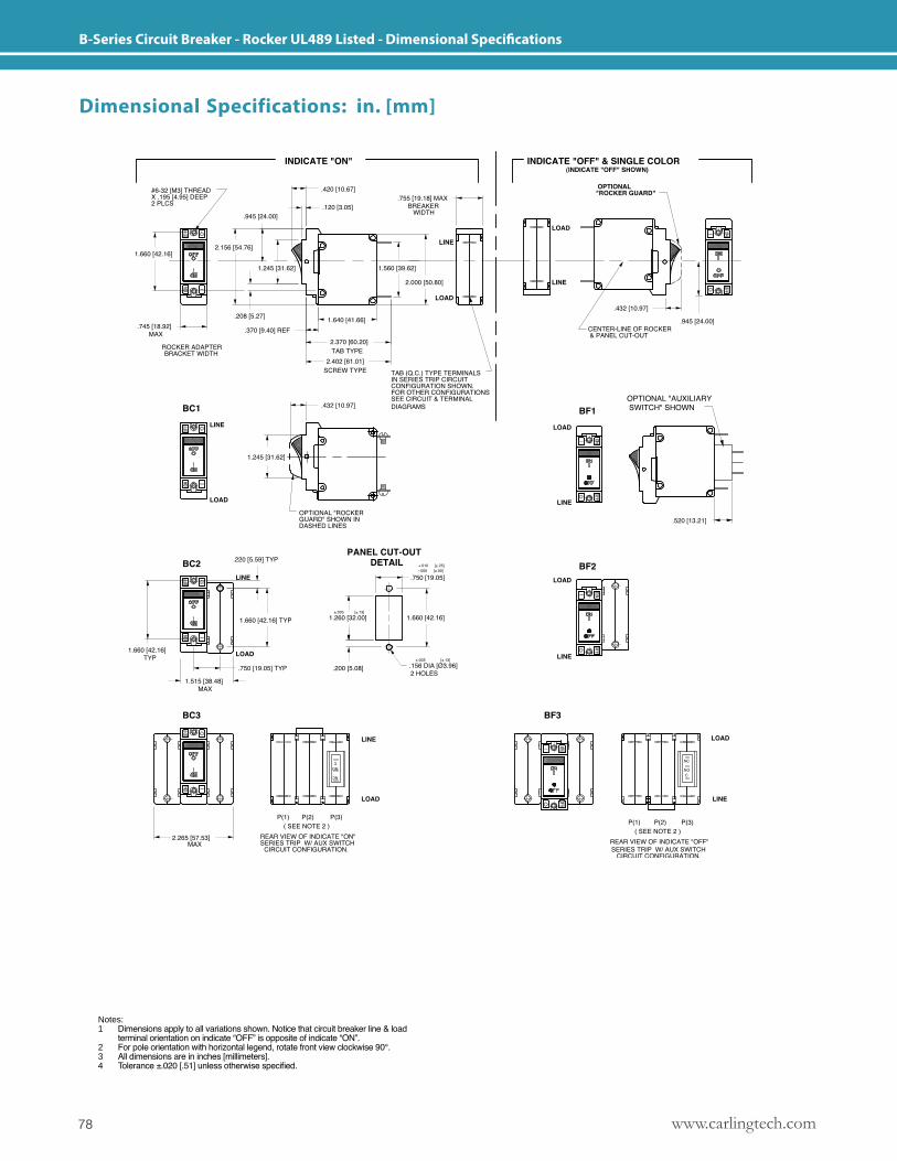
www.carlingtech.com78
B-Series Circuit Breaker - Rocker UL489 Listed - Dimensional Specifications
Dimensional Specifications: in. [mm]
Notes: 1 Dimensions apply to all variations shown. Notice that circuit breaker line & load terminal orientation on indicate “OFF” is opposite of indicate “ON”.2 For pole orientation with horizontal legend, rotate front view clockwise 90°.3 All dimensions are in inches [millimeters].4 Tolerance ±.020 [.51] unless otherwise specified.
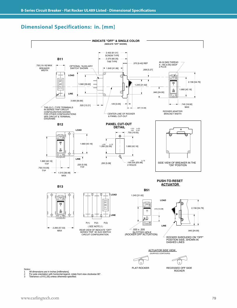
79www.carlingtech.com
B-Series Circuit Breaker - Flat Rocker UL489 Listed - Dimensional Specifications
Notes: 1 All dimensions are in inches [millimeters].2 For pole orientation with horizontal legend, rotate front view clockwise 90°.3 Tolerance ±.010 [.25] unless otherwise specified.
Dimensional Specifications: in. [mm]
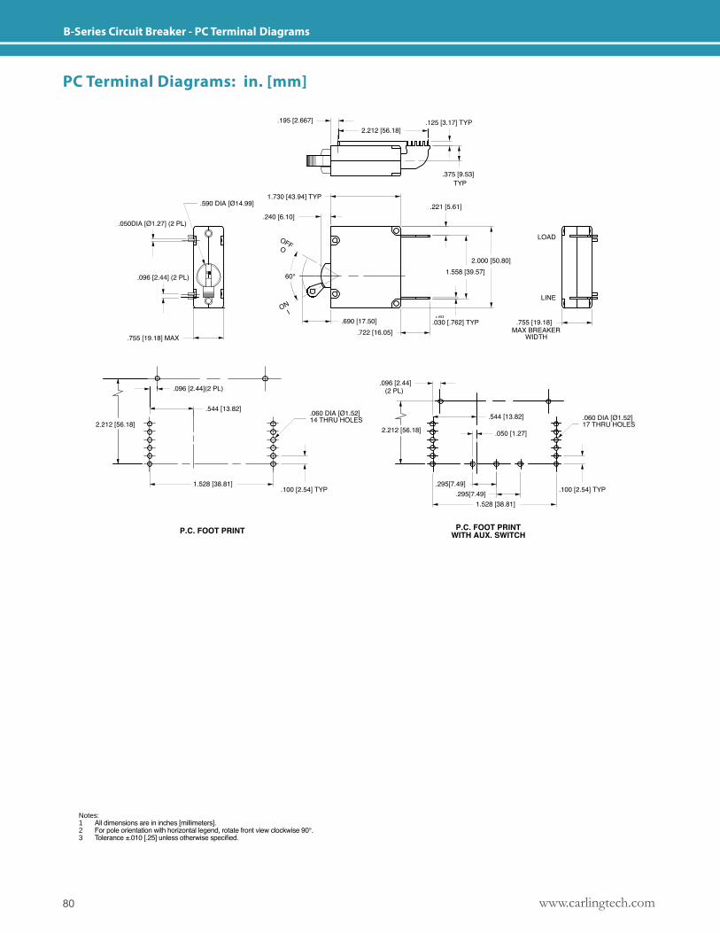
www.carlingtech.com80
B-Series Circuit Breaker - PC Terminal Diagrams
Notes: 1 All dimensions are in inches [millimeters].2 For pole orientation with horizontal legend, rotate front view clockwise 90°.3 Tolerance ±.010 [.25] unless otherwise specified.
PC Terminal Diagrams: in. [mm]
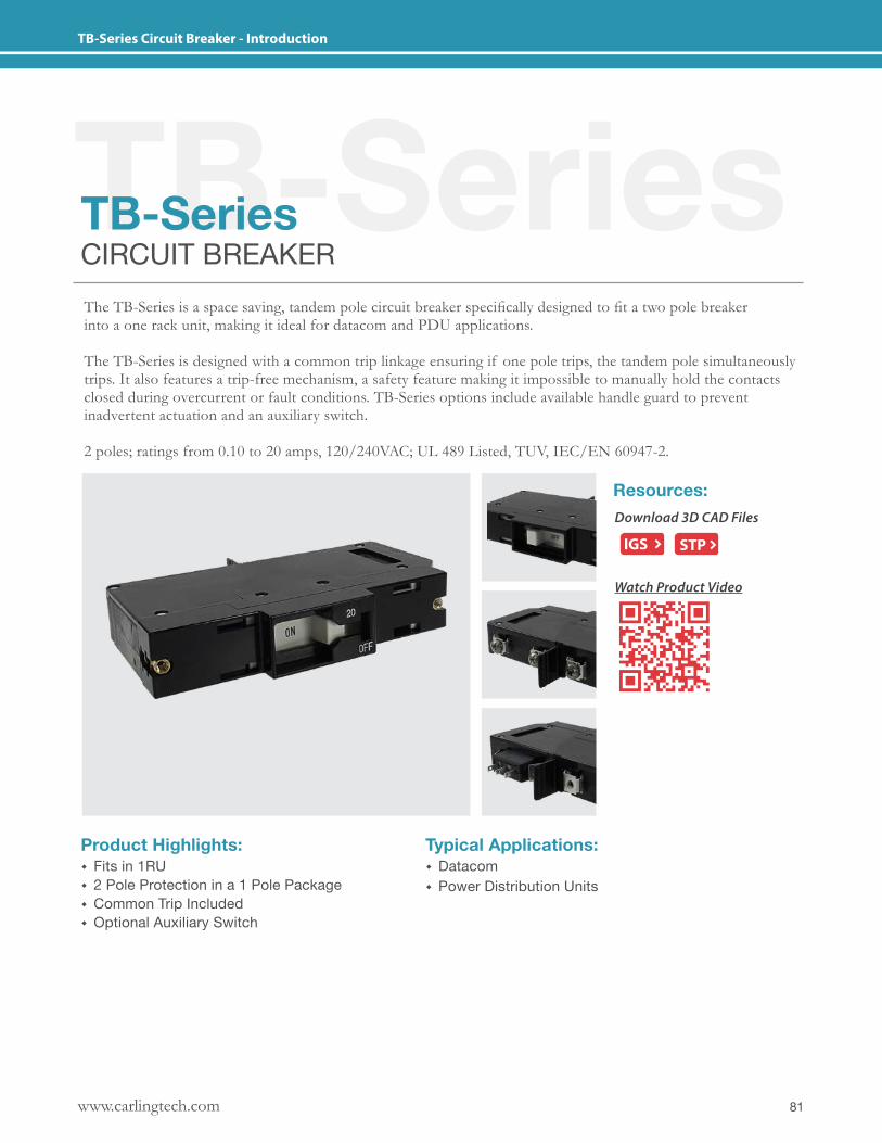
81www.carlingtech.com
TB-Series Circuit Breaker - Introduction
TB-SeriesTB-SeriesCIRCUIT BREAKERThe TB-Series is a space saving, tandem pole circuit breaker specifically designed to fit a two pole breakerinto a one rack unit, making it ideal for datacom and PDU applications.
The TB-Series is designed with a common trip linkage ensuring if one pole trips, the tandem pole simultaneously trips. It also features a trip-free mechanism, a safety feature making it impossible to manually hold the contacts closed during overcurrent or fault conditions. TB-Series options include available handle guard to prevent inadvertent actuation and an auxiliary switch.
2 poles; ratings from 0.10 to 20 amps, 120/240VAC; UL 489 Listed, TUV, IEC/EN 60947-2.
Product Highlights: � Fits in 1RU � 2 Pole Protection in a 1 Pole Package � Common Trip Included � Optional Auxiliary Switch
Typical Applications: � Datacom � Power Distribution Units
Resources:Download 3D CAD Files
IGS STP
Watch Product Video
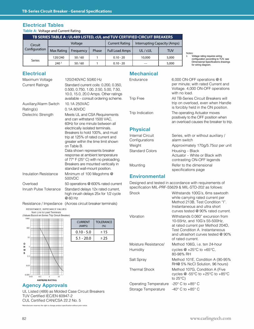
www.carlingtech.com82
TB-Series Circuit Breaker - General Specifications
*Manufacturer reserves the right to change product specification without prior notice.
Mechanical
Physical
Agency Approvals
Environmental
Electrical
Designed and tested in accordance with requirements of specificationMIL-PRF-55629&MIL-STD-202asfollows:
Maximum Voltage 120/240VAC 50/60 HzCurrent Ratings Standard current coils: 0.200, 0.350, 0.500, 0.750, 1.00, 2.50, 5.00, 7.50, 10.0, 15.0, 20.0 Amps. Other ratings available - consult ordering scheme.Auxiliary/Alarm Switch 10.1A 250VACRating(s) 0.1A 80VDCDielectric Strength Meets UL and CSA Requirements and can withstand 1500 VAC, 60Hz for one minute between all electrically isolated terminals. Breakers to hold 100%, and must trip at 125% of rated current and greater within the time limit shown on Table B. Data shown represents breaker response at ambient temperature of 77° F (25° C) with no preloading. Breakers are mounted vertically in standard wall-mount position. Insulation Resistance Minimum of 100 Megohms @ 500VDCOverload 50 operations @ 600% rated currentInrush Pulse Tolerance Standard delays 12x rated current, high inrush delays 25x for 1/2 cycle @ 60 HzResistance / Impedance (Across circuit breaker terminals)
Endurance 6,000 ON-OFF operations @ 6 per minute; with rated Current and Voltage. 4,000 ON-OFF operations with no load.Trip Free All TB-Series Circuit Breakers will trip on overload, even when Handle is forcibly held in the ON position.Trip Indication The operating Actuator moves positively to the OFF position when an overload causes the breaker to trip.
Internal Circuit Series, with or without auxiliary /Configurations alarmswitchWeight Approximately 170g/5.75oz per unitStandard Colors Housing – Black Actuator – White or Black with contrasting ON-OFF legendsMounting Refer to the dimensional specificationspage
UL Listed (489) as Molded Case Circuit BreakersTUVCertifiedIEC/EN60947-2CULCertifiedCAN/CSA22.2No.5
Shock Withstands 100G’s, 6ms sawtooth while carrying rated current per Method 213B, Test Condition “I”. Instantaneous and ultra short curves tested @ 90% rated current.Vibration Withstands 0.060” excursion from 10-55Hz, and 10G’s 55-500Hz, at rated current per Method 204D, Test Condition A. Instantaneous and ultrashort curves tested @ 90% of rated current.Moisture Resistance/ Method 106G, i.e. ten 24-hour Humidity cycles @ +25°C to +65°C, 80-98% RHSalt Spray Method 101E, Condition A (90-95% RH@ 5% NcCl Solution, 96 hours)Thermal Shock Method 107G, Condition A (Five cycles @ -55°C to +25°C to +85°C to 25°C)Operating Temperature -20° C to +85° CStorage Temperature -40° C to +85° C
Electrical TablesTable A: Voltage and Current Rating
TB SERIES TABLE A : UL489 LISTED, cUL and TUV CERTIFIED CIRCUIT BREAKERS
Circuit Configuration
Voltage Current Rating Interrupting Capacity (Amps)
Max Rating Frequency Phase Full Load Amps UL / cUL TUV
Series120/240 50 / 60 1 0.10 - 20 10,000 5,000
240 1 50 / 60 1 0.10 - 20 --- 5,000
CURRENT (AMPS)
TOLERANCE (%)
0.10 - 5.0 ± 155.1 - 20.0 ± 25
Notes: 1 Voltage rating requires wiring configuration according to TUV, see Dimensional Specifications drawings for wiring diagram.
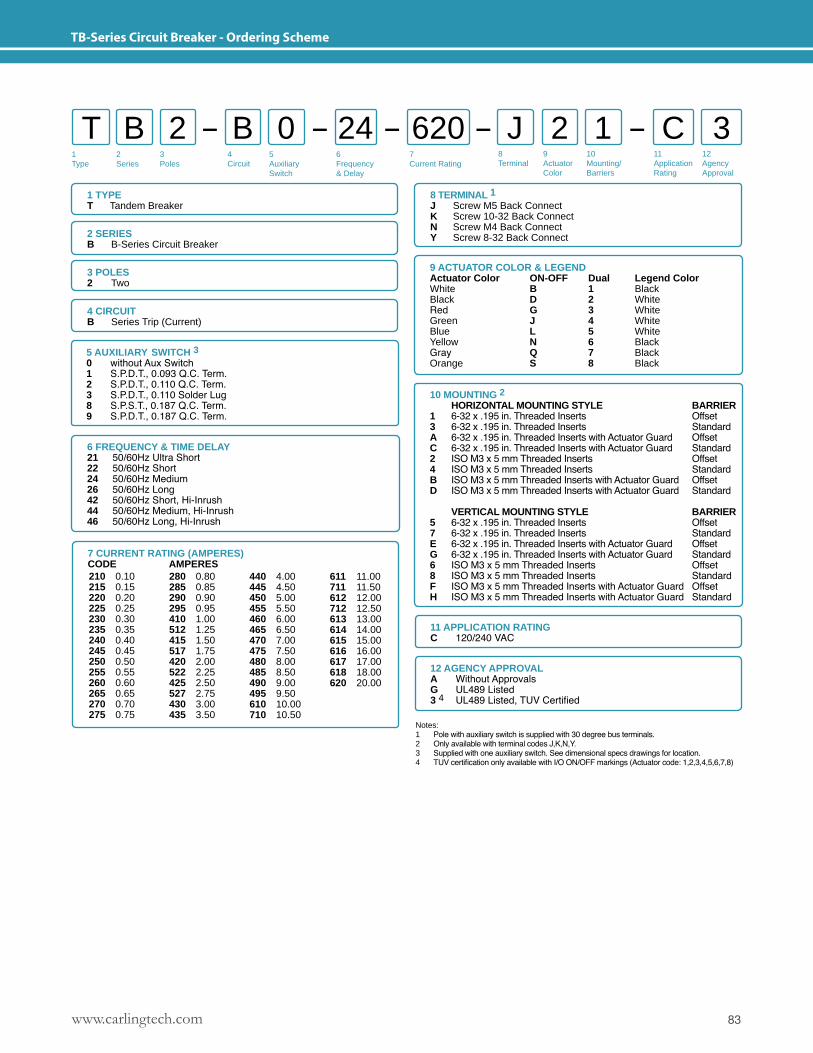
83www.carlingtech.com
TB-Series Circuit Breaker - Ordering Scheme
1Type
2Series
3Poles
5Auxiliary Switch
6Frequency& Delay
7Current Rating
8Terminal
9ActuatorColor
10Mounting/Barriers
11ApplicationRating
12AgencyApproval
4 Circuit
T B B J 12 0 2 C 324 620
1 TYPET Tandem Breaker
2 SERIESB B-Series Circuit Breaker
10 MOUNTING 2 HORIZONTAL MOUNTING STYLE BARRIER1 6- 32 x .195 in. Threaded Inserts Offset3 6- 32 x .195 in. Threaded Inserts StandardA 6- 32 x .195 in. Threaded Inserts with Actuator Guard OffsetC 6- 32 x .195 in. Threaded Inserts with Actuator Guard Standard2 ISO M3 x 5 mm Threaded Inserts Offset4 ISO M3 x 5 mm Threaded Inserts StandardB ISO M3 x 5 mm Threaded Inserts with Actuator Guard OffsetD ISO M3 x 5 mm Threaded Inserts with Actuator Guard Standard
VERTICAL MOUNTING STYLE BARRIER5 6-32 x .195 in. Threaded Inserts Offset7 6-32 x .195 in. Threaded Inserts StandardE 6-32 x .195 in. Threaded Inserts with Actuator Guard OffsetG 6-32 x .195 in. Threaded Inserts with Actuator Guard Standard6 ISO M3 x 5 mm Threaded Inserts Offset8 ISO M3 x 5 mm Threaded Inserts StandardF ISO M3 x 5 mm Threaded Inserts with Actuator Guard OffsetH ISO M3 x 5 mm Threaded Inserts with Actuator Guard Standard
3 POLES 2 Two
9 ACTUATOR COLOR & LEGENDActuator Color ON-OFF Dual Legend ColorWhite B 1 BlackBlack D 2 WhiteRed G 3 WhiteGreen J 4 WhiteBlue L 5 WhiteYellow N 6 BlackGray Q 7 BlackOrange S 8 Black
Notes: 1 Pole with auxiliary switch is supplied with 30 degree bus terminals.2 Only available with terminal codes J,K,N,Y.3 Supplied with one auxiliary switch. See dimensional specs drawings for location.4 TUV certification only available with I/O ON/OFF markings (Actuator code: 1,2,3,4,5,6,7,8)
4 CIRCUITB Series Trip (Current)
11 APPLICATION RATINGC 120/240 VAC
12 AGENCY APPROVALA Without ApprovalsG UL489 Listed3 4 UL489 Listed, TUV Certified
8 TERMINAL 1 J Screw M5 Back Connect K Screw 10-32 Back Connect N Screw M4 Back ConnectY Screw 8-32 Back Connect
5 AUXILIARY SWITCH 30 without Aux Switch 1 S.P.D.T., 0.093 Q.C. Term.2 S.P.D.T., 0.110 Q.C. Term. 3 S.P.D.T., 0.110 Solder Lug 8 S.P.S.T., 0.187 Q.C. Term.9 S.P.D.T., 0.187 Q.C. Term.
6 FREQUENCY & TIME DELAY21 50/60Hz Ultra Short22 50/60Hz Short24 50/60Hz Medium26 50/60Hz Long42 50/60Hz Short, Hi-Inrush 44 50/60Hz Medium, Hi-Inrush 46 50/60Hz Long, Hi-Inrush
7 CURRENT RATING (AMPERES)CODE AMPERES 210 0.10215 0.15220 0.20225 0.25230 0.30235 0.35240 0.40245 0.45250 0.50255 0.55260 0.60265 0.65270 0.70275 0.75
280 0.80285 0.85290 0.90295 0.95410 1.00512 1.25415 1.50517 1.75420 2.00522 2.25425 2.50527 2.75430 3.00435 3.50
440 4.00445 4.50450 5.00455 5.50460 6.00465 6.50470 7.00475 7.50480 8.00485 8.50490 9.00495 9.50610 10.00710 10.50
611 11.00711 11.50612 12.00712 12.50613 13.00614 14.00615 15.00616 16.00617 17.00618 18.00620 20.00
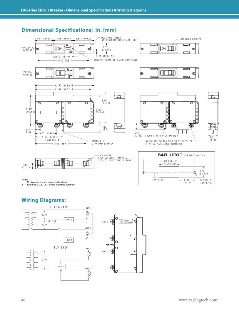
www.carlingtech.com84
TB-Series Circuit Breaker - Dimensional Specifications & Wiring Diagrams
Dimensional Specifications: in. [mm]
Wiring Diagrams:
Notes: 1 All dimensions are in inches [millimeters].2 Tolerance ± 0.20 [.51] unless otherwise specified.
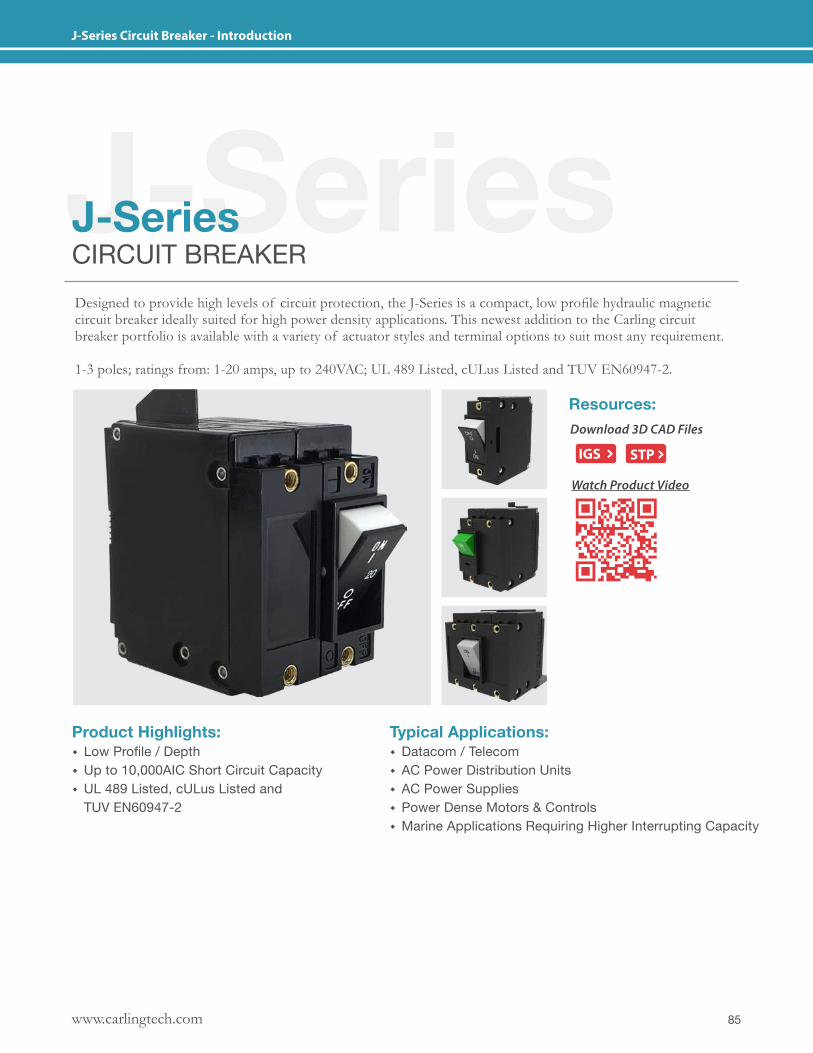
85www.carlingtech.com
J-Series Circuit Breaker - Introduction
J-SeriesJ-SeriesCIRCUIT BREAKERDesigned to provide high levels of circuit protection, the J-Series is a compact, low profile hydraulic magnetic circuit breaker ideally suited for high power density applications. This newest addition to the Carling circuit breaker portfolio is available with a variety of actuator styles and terminal options to suit most any requirement.
1-3 poles; ratings from: 1-20 amps, up to 240VAC; UL 489 Listed, cULus Listed and TUV EN60947-2.
Product Highlights: � Low Profile / Depth � Up to 10,000AIC Short Circuit Capacity � UL 489 Listed, cULus Listed and TUV EN60947-2
Typical Applications: � Datacom / Telecom � AC Power Distribution Units � AC Power Supplies � Power Dense Motors & Controls � Marine Applications Requiring Higher Interrupting Capacity
Resources:Download 3D CAD Files
IGS STP
Watch Product Video
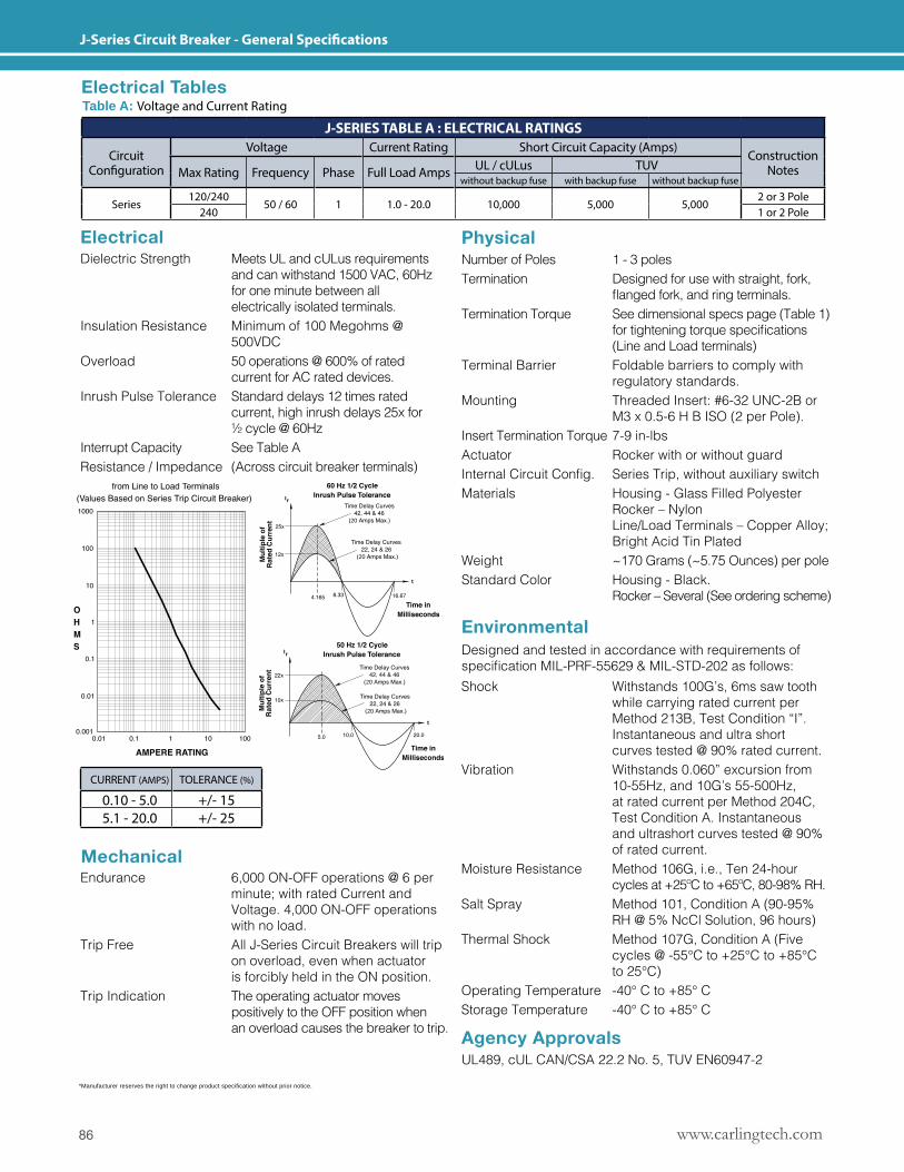
www.carlingtech.com86
J-Series Circuit Breaker - General Specifications
*Manufacturer reserves the right to change product specification without prior notice.
Mechanical
Physical
Agency Approvals
Environmental
Electrical
Designed and tested in accordance with requirements of specificationMIL-PRF-55629&MIL-STD-202asfollows:
Dielectric Strength Meets UL and cULus requirements and can withstand 1500 VAC, 60Hz for one minute between all electrically isolated terminals. Insulation Resistance Minimum of 100 Megohms @ 500VDCOverload 50 operations @ 600% of rated current for AC rated devices.Inrush Pulse Tolerance Standard delays 12 times rated current, high inrush delays 25x for ½ cycle @ 60HzInterrupt Capacity See Table AResistance / Impedance (Across circuit breaker terminals)
Endurance 6,000 ON-OFF operations @ 6 per minute; with rated Current and Voltage. 4,000 ON-OFF operations with no load.Trip Free All J-Series Circuit Breakers will trip on overload, even when actuator is forcibly held in the ON position.Trip Indication The operating actuator moves positively to the OFF position when an overload causes the breaker to trip.
Number of Poles 1 - 3 polesTermination Designed for use with straight, fork, flangedfork,andringterminals.Termination Torque See dimensional specs page (Table 1) fortighteningtorquespecifications (Line and Load terminals)Terminal Barrier Foldable barriers to comply with regulatory standards.Mounting Threaded Insert: #6-32 UNC-2B or M3 x 0.5-6 H B ISO (2 per Pole). Insert Termination Torque 7-9 in-lbsActuator Rocker with or without guard InternalCircuitConfig. SeriesTrip,withoutauxiliaryswitchMaterials Housing - Glass Filled Polyester Rocker – Nylon Line/Load Terminals – Copper Alloy; Bright Acid Tin PlatedWeight ~170 Grams (~5.75 Ounces) per poleStandard Color Housing - Black. Rocker – Several (See ordering scheme)
UL489, cUL CAN/CSA 22.2 No. 5, TUV EN60947-2
Shock Withstands 100G’s, 6ms saw tooth while carrying rated current per Method 213B, Test Condition “I”. Instantaneous and ultra short curves tested @ 90% rated current.Vibration Withstands 0.060” excursion from 10-55Hz, and 10G’s 55-500Hz, at rated current per Method 204C, Test Condition A. Instantaneous and ultrashort curves tested @ 90% of rated current.Moisture Resistance Method 106G, i.e., Ten 24-hour cycles at +25ºC to +65ºC, 80-98% RH.Salt Spray Method 101, Condition A (90-95% RH @ 5% NcCl Solution, 96 hours)Thermal Shock Method 107G, Condition A (Five cycles @ -55°C to +25°C to +85°C to 25°C)Operating Temperature -40° C to +85° CStorage Temperature -40° C to +85° C
Electrical TablesTable A: Voltage and Current Rating
J-SERIES TABLE A : ELECTRICAL RATINGS
Circuit Configuration
Voltage Current Rating Short Circuit Capacity (Amps)Construction
NotesMax Rating Frequency Phase Full Load Amps UL / cULus TUVwithout backup fuse with backup fuse without backup fuse
Series120/240
50 / 60 1 1.0 - 20.0 10,000 5,000 5,0002 or 3 Pole
240 1 or 2 Pole
20
20
20
20
CURRENT (AMPS) TOLERANCE (%)
0.10 - 5.0 +/- 155.1 - 20.0 +/- 25
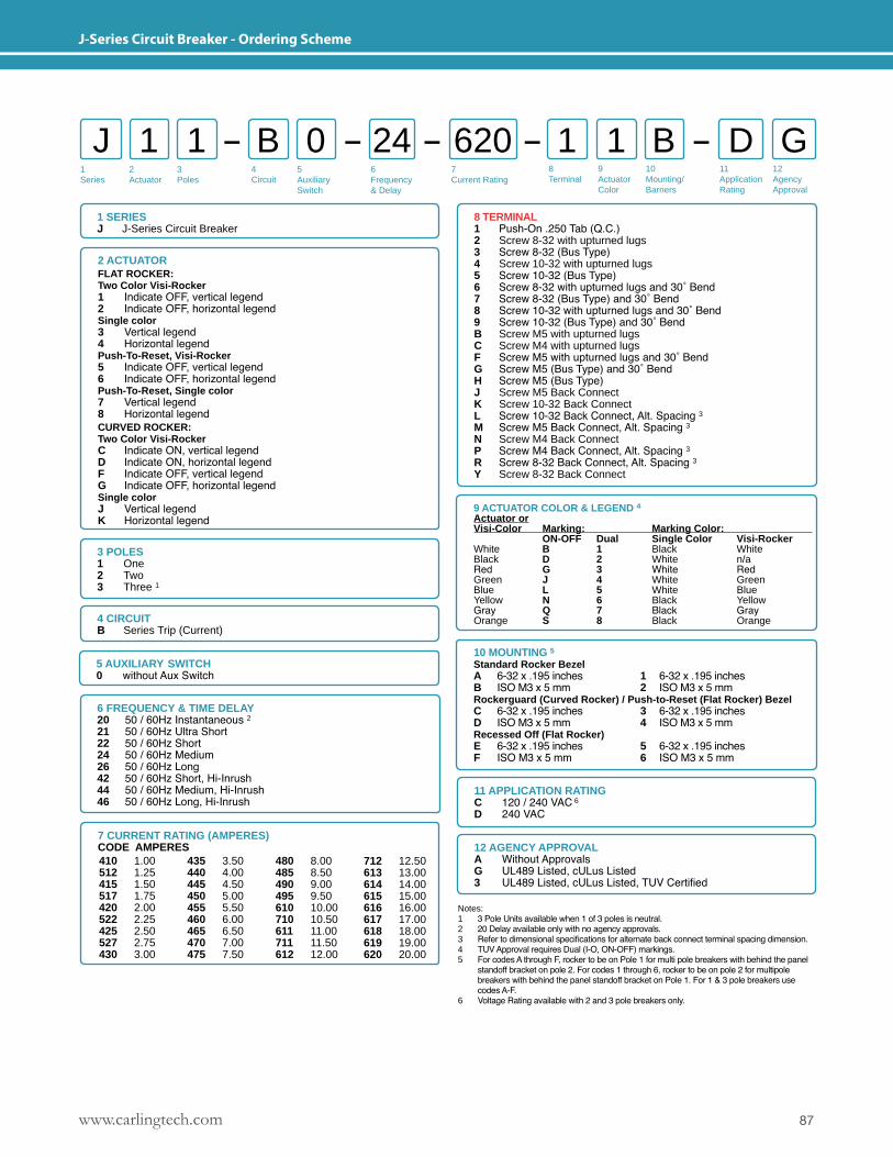
87www.carlingtech.com
J-Series Circuit Breaker - Ordering Scheme
1Series
2Actuator
3Poles
5Auxiliary Switch
6Frequency& Delay
7Current Rating
8Terminal
9ActuatorColor
10Mounting/Barriers
11ApplicationRating
12AgencyApproval
4 Circuit
J 1 B 1 B1 0 1 D G24 620
1 SERIESJ J-Series Circuit Breaker
10 MOUNTING 5Standard Rocker BezelA 6- 32 x .195 inches 1 6- 32 x .195 inchesB ISO M3 x 5 mm 2 ISO M3 x 5 mmRockerguard (Curved Rocker) / Push-to-Reset (Flat Rocker) BezelC 6- 32 x .195 inches 3 6- 32 x .195 inchesD ISO M3 x 5 mm 4 ISO M3 x 5 mmRecessed Off (Flat Rocker)E 6-32 x .195 inches 5 6-32 x .195 inchesF ISO M3 x 5 mm 6 ISO M3 x 5 mm
3 POLES 1 One2 Two 3 Three 1
Notes: 1 3 Pole Units available when 1 of 3 poles is neutral.2 20 Delay available only with no agency approvals.3 Refer to dimensional specifications for alternate back connect terminal spacing dimension.4 TUV Approval requires Dual (I-O, ON-OFF) markings.5 For codes A through F, rocker to be on Pole 1 for multi pole breakers with behind the panel standoff bracket on pole 2. For codes 1 through 6, rocker to be on pole 2 for multipole breakers with behind the panel standoff bracket on Pole 1. For 1 & 3 pole breakers use codes A-F.6 Voltage Rating available with 2 and 3 pole breakers only.
4 CIRCUITB Series Trip (Current)
11 APPLICATION RATINGC 120 / 240 VAC 6
D 240 VAC
12 AGENCY APPROVALA Without ApprovalsG UL489 Listed, cULus Listed3 UL489 Listed, cULus Listed, TUV Certified
8 TERMINAL 1 Push-On .250 Tab (Q.C.)2 Screw 8-32 with upturned lugs3 Screw 8-32 (Bus Type)4 Screw 10-32 with upturned lugs5 Screw 10-32 (Bus Type)6 Screw 8-32 with upturned lugs and 30˚ Bend7 Screw 8-32 (Bus Type) and 30˚ Bend8 Screw 10-32 with upturned lugs and 30˚ Bend9 Screw 10-32 (Bus Type) and 30˚ BendB Screw M5 with upturned lugsC Screw M4 with upturned lugsF Screw M5 with upturned lugs and 30˚ BendG Screw M5 (Bus Type) and 30˚ BendH Screw M5 (Bus Type) J Screw M5 Back Connect K Screw 10-32 Back Connect L Screw 10-32 Back Connect, Alt. Spacing 3M Screw M5 Back Connect, Alt. Spacing 3N Screw M4 Back ConnectP Screw M4 Back Connect, Alt. Spacing 3R Screw 8-32 Back Connect, Alt. Spacing 3Y Screw 8-32 Back Connect
5 AUXILIARY SWITCH0 without Aux Switch
6 FREQUENCY & TIME DELAY20 50 / 60Hz Instantaneous 221 50 / 60Hz Ultra Short22 50 / 60Hz Short24 50 / 60Hz Medium26 50 / 60Hz Long42 50 / 60Hz Short, Hi-Inrush 44 50 / 60Hz Medium, Hi-Inrush 46 50 / 60Hz Long, Hi-Inrush
7 CURRENT RATING (AMPERES)CODE AMPERES 410 1.00512 1.25415 1.50517 1.75420 2.00522 2.25425 2.50527 2.75430 3.00
435 3.50440 4.00445 4.50450 5.00455 5.50460 6.00465 6.50470 7.00475 7.50
480 8.00485 8.50490 9.00495 9.50610 10.00710 10.50611 11.00711 11.50612 12.00
712 12.50613 13.00614 14.00615 15.00616 16.00617 17.00618 18.00619 19.00620 20.00
9 ACTUATOR COLOR & LEGEND 4Actuator orVisi-Color Marking: Marking Color: ON-OFF Dual Single Color Visi-RockerWhite B 1 Black WhiteBlack D 2 White n/aRed G 3 White RedGreen J 4 White GreenBlue L 5 White BlueYellow N 6 Black YellowGray Q 7 Black GrayOrange S 8 Black Orange
2 ACTUATORFLAT ROCKER:Two Color Visi-Rocker 1 Indicate OFF, vertical legend2 Indicate OFF, horizontal legendSingle color3 Vertical legend4 Horizontal legendPush-To-Reset, Visi-Rocker5 Indicate OFF, vertical legend6 Indicate OFF, horizontal legendPush-To-Reset, Single color7 Vertical legend8 Horizontal legendCURVED ROCKER:Two Color Visi-RockerC Indicate ON, vertical legendD Indicate ON, horizontal legendF Indicate OFF, vertical legendG Indicate OFF, horizontal legendSingle colorJ Vertical legendK Horizontal legend
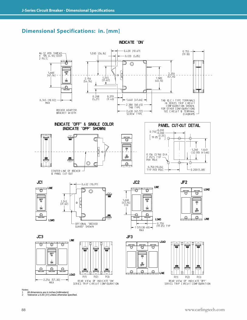
www.carlingtech.com88
J-Series Circuit Breaker - Dimensional Specifications
Dimensional Specifications: in. [mm]
Notes: 1 All dimensions are in inches [millimeters].2 Tolerance ± 0.20 [.51] unless otherwise specified.
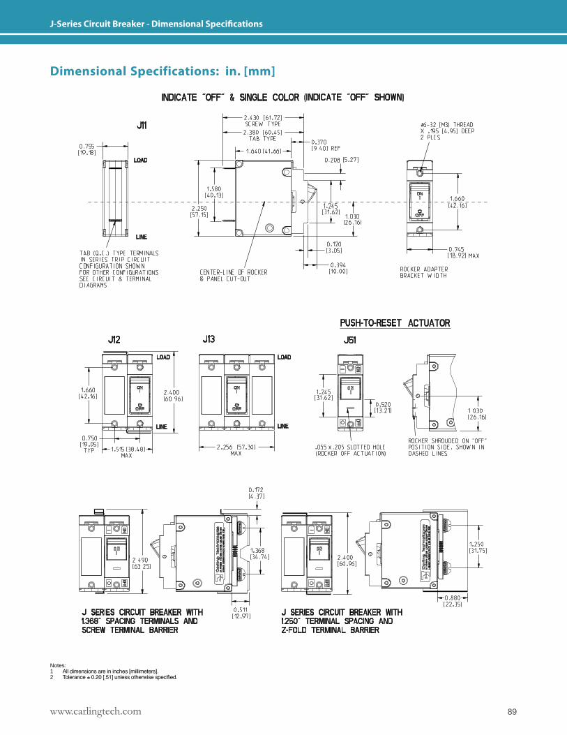
89www.carlingtech.com
J-Series Circuit Breaker - Dimensional Specifications
Dimensional Specifications: in. [mm]
Notes: 1 All dimensions are in inches [millimeters].2 Tolerance ± 0.20 [.51] unless otherwise specified.
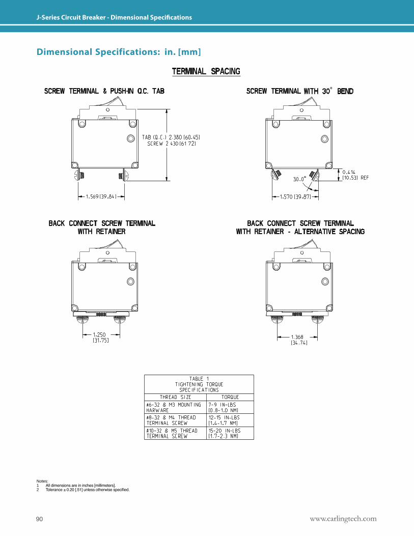
www.carlingtech.com90
J-Series Circuit Breaker - Dimensional Specifications
Dimensional Specifications: in. [mm]
Notes: 1 All dimensions are in inches [millimeters].2 Tolerance ± 0.20 [.51] unless otherwise specified.
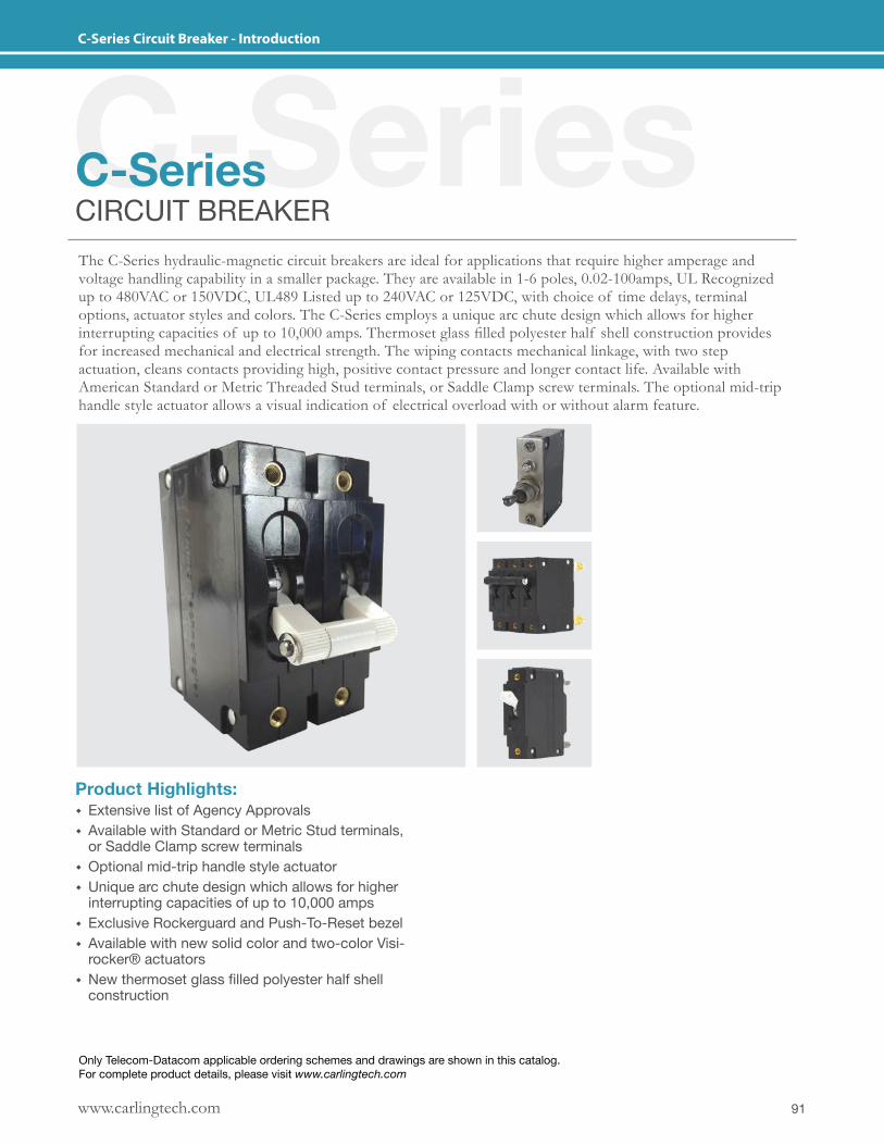
91www.carlingtech.com
C-Series Circuit Breaker - Introduction
C-SeriesC-SeriesCIRCUIT BREAKERThe C-Series hydraulic-magnetic circuit breakers are ideal for applications that require higher amperage and voltage handling capability in a smaller package. They are available in 1-6 poles, 0.02-100amps, UL Recognized up to 480VAC or 150VDC, UL489 Listed up to 240VAC or 125VDC, with choice of time delays, terminal options, actuator styles and colors. The C-Series employs a unique arc chute design which allows for higher interrupting capacities of up to 10,000 amps. Thermoset glass filled polyester half shell construction provides for increased mechanical and electrical strength. The wiping contacts mechanical linkage, with two step actuation, cleans contacts providing high, positive contact pressure and longer contact life. Available with American Standard or Metric Threaded Stud terminals, or Saddle Clamp screw terminals. The optional mid-trip handle style actuator allows a visual indication of electrical overload with or without alarm feature.
Product Highlights: � Extensive list of Agency Approvals � Available with Standard or Metric Stud terminals, or Saddle Clamp screw terminals
� Optional mid-trip handle style actuator � Unique arc chute design which allows for higher interrupting capacities of up to 10,000 amps
� Exclusive Rockerguard and Push-To-Reset bezel � Available with new solid color and two-color Visi-rocker® actuators
� New thermoset glass filled polyester half shell construction
Only Telecom-Datacom applicable ordering schemes and drawings are shown in this catalog. For complete product details, please visit www.carlingtech.com
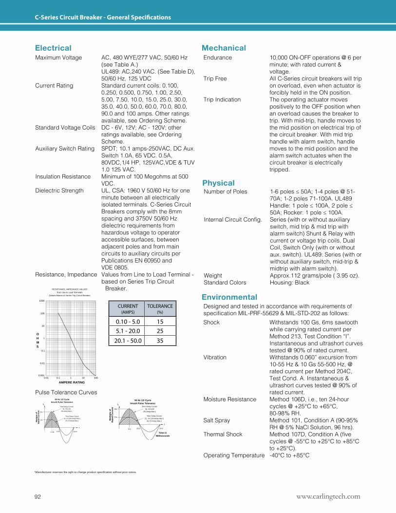
www.carlingtech.com92
C-Series Circuit Breaker - General Specifications
*Manufacturer reserves the right to change product specification without prior notice.
Mechanical
Physical
Environmental
Electrical
0.1
0.10.010.001
0.01
1
10
100
1000
15%
25%
35%
1 10010
TOLERANCE(%)
OHMS
CURRENT(AMPS)
FIGURE 1
0.100 - 5.0
5.1 - 20.0
20.1 - 100
RESISTANCE, IMPEDANCE VALUES
from Line to Load Terminals
(Values Based on Series Trip Circuit Breaker)
AMPERE RATING
Time Delay Curves42, 44 & 46
(50 Amps Max.)
16.67
t
Mu
ltip
le o
fR
ated
Cu
rren
t
rI
4.165 8.33
25x
12x
20.0
Time Delay Curves22, 24 (100 Amps Max.)
26 (70 Amps Max.)
Time in Milliseconds
t
Time Delay Curves22, 24 (100 Amps Max.)
26 (70 Amps Max.)
60 Hz 1/2 CycleInrush Pulse Tolerance
50 Hz 1/2 CycleInrush Pulse Tolerance
10.0
Time Delay Curves42, 44 & 46
(50 Amps Max.)
22x
10x
Mu
ltip
le o
fR
ated
Cu
rren
t
5.0
rI
Time Delay Curves42, 44 & 46
(50 Amps Max.)
16.67
t
Mu
ltip
le o
fR
ated
Cu
rren
t
rI
4.165 8.33
25x
12x
20.0
Time Delay Curves22, 24 (100 Amps Max.)
26 (70 Amps Max.)
Time in Milliseconds
t
Time Delay Curves22, 24 (100 Amps Max.)
26 (70 Amps Max.)
60 Hz 1/2 CycleInrush Pulse Tolerance
50 Hz 1/2 CycleInrush Pulse Tolerance
10.0
Time Delay Curves42, 44 & 46
(50 Amps Max.)
22x
10x
Mu
ltip
le o
fR
ated
Cu
rren
t
5.0
rI
Maximum Voltage AC, 480 WYE/277 VAC, 50/60 Hz (see Table A.) UL489: AC,240 VAC. (See Table D), 50/60 Hz, 125 VDCCurrent Rating Standard current coils: 0.100, 0.250, 0.500, 0.750, 1.00, 2.50, 5.00, 7.50, 10.0, 15.0, 25.0, 30.0, 35.0, 40.0, 50.0, 60.0, 70.0, 80.0, 90.0 and 100 amps. Other ratings available, see Ordering Scheme.Standard Voltage Coils DC - 6V, 12V; AC - 120V; other ratings available, see Ordering Scheme.Auxiliary Switch Rating SPDT; 10.1 amps-250VAC, DC Aux. Switch 1.0A, 65 VDC. 0.5A, 80VDC,1/4 HP, 125VAC,VDE & TUV 1.0 125 VAC.Insulation Resistance Minimum of 100 Megohms at 500 VDC.Dielectric Strength UL, CSA: 1960 V 50/60 Hz for one minute between all electrically isolated terminals. C-Series Circuit Breakers comply with the 8mm spacing and 3750V 50/60 Hz dielectric requirements from hazardous voltage to operator accessible surfaces, between adjacent poles and from main circuits to auxiliary circuits per Publications EN 60950 and VDE 0805.Resistance, Impedance Values from Line to Load Terminal - based on Series Trip Circuit Breaker.
Endurance 10,000 ON-OFF operations @ 6 per minute; with rated current & voltage.Trip Free All C-Series circuit breakers will trip on overload, even when actuator is forcibly held in the ON position.Trip Indication The operating actuator moves positively to the OFF position when an overload causes the breaker to trip. With mid-trip, handle moves to the mid position on electrical trip of the circuit breaker. With mid trip handle with alarm switch, handle moves to the mid position and the alarm switch actuates when the circuit breaker is electrically tripped.
NumberofPoles 1-6poles≤50A;1-4poles@51- 70A; 1-2 poles 71-100A. UL489 Handle:1pole≤100A,2pole≤ 50A;Rocker:1pole≤100A.InternalCircuitConfig. Series(withorwithoutauxiliary switch, mid trip & mid trip with alarm switch) Shunt & Relay with current or voltage trip coils, Dual Coil, Switch Only (with or without aux. switch). UL489: Series (with or without auxiliary switch, mid-trip & midtrip with alarm switch).Weight Approx.112 grams/pole ( 3.95 oz).Standard Colors Housing: Black
Designed and tested in accordance with requirements of specificationMIL-PRF-55629&MIL-STD-202asfollows:Shock Withstands 100 Gs, 6ms sawtooth while carrying rated current per Method 213, Test Condition “I”. Instantaneous and ultrashort curves tested @ 90% of rated current.Vibration Withstands 0.060” excursion from 10-55 Hz & 10 Gs 55-500 Hz, @ rated current per Method 204C, Test Cond. A. Instantaneous & ultrashort curves tested @ 90% of rated current.Moisture Resistance Method 106D, i.e., ten 24-hour cycles @ +25°C to +65°C, 80-98% RH.Salt Spray Method 101, Condition A (90-95% RH @ 5% NaCl Solution, 96 hrs).ThermalShock Method107D,ConditionA(five cycles @ -55°C to +25°C to +85°C to +25°C).Operating Temperature -40°C to +85°C
Pulse Tolerance Curves
CURRENT (AMPS)
TOLERANCE (%)
0.10 - 5.0 155.1 - 20.0 25
20.1 - 50.0 35
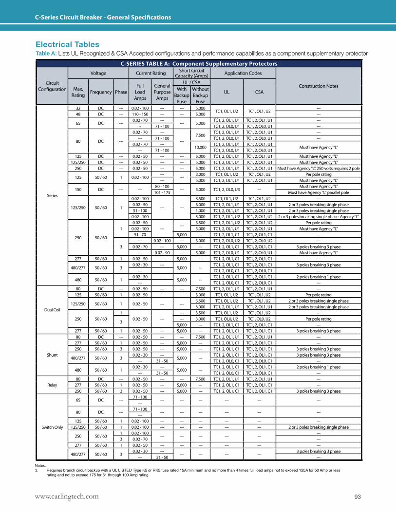
93www.carlingtech.com
C-Series Circuit Breaker - General Specifications
Electrical TablesTable A:ListsULRecognized&CSAAcceptedconfigurationsandperformancecapabilitiesasacomponentsupplementaryprotector
Notes:1. Requires branch circuit backup with a UL LISTED Type K5 or RK5 fuse rated 15A minimum and no more than 4 times full load amps not to exceed 125A for 50 Amp or less
rating and not to exceed 175 for 51 through 100 Amp rating
C-SERIES TABLE A: Component Supplementary Protectors
Circuit Configuration
Voltage Current Rating Short Circuit Capacity (Amps) Application Codes
Construction NotesMax. Rating Frequency Phase
Full Load Amps
General Purpose
Amps
UL / CSA
UL CSAWith Backup
Fuse
Without Backup
Fuse
Series
32 DC --- 0.02 - 100 --- --- 5,000TC1, OL1, U2 TC1, OL1, U2
---48 DC --- 110 - 150 --- --- 5,000 ---
65 DC ---0.02 - 70 ---
--- 5,000TC1, 2, OL1, U1 TC1, 2, OL1, U1 ---
- 71 - 100 TC1, 2, OL0, U1 TC1, 2, OL0, U1 ---
80 DC ---
0.02 - 70 ---
---7,500
TC1, 2, OL1, U1 TC1, 2, OL1, U1 ------ 71 - 100 TC1, 2, OL0, U1 TC1, 2, OL0, U1 ---
0.02 - 70 ---10,000
TC1, 2, OL1, U1 TC1, 2, OL1, U1Must have Agency "L"
--- 71 - 100 TC1, 2, OL0, U1 TC1, 2, OL0, U1125 DC --- 0.02 - 50 --- --- 5,000 TC1, 2, OL1, U1 TC1, 2, OL1, U1 Must have Agency "L"
125/250 DC --- 0.02 - 50 --- --- 5,000 TC1, 2, OL1, U1 TC1, 2, OL1, U1 Must have Agency "L"250 DC --- 0.02 - 50 --- --- 5,000 TC1, 2, OL1, U1 TC1, 2, OL1, U1 Must have Agency "L". 250 volts requires 2 pole
125 50 / 60 1 0.02 - 100---
---3,000 TC1, OL1, U2 TC1, OL1, U2 Per pole rating
--- 5,000 TC1, 2, OL1, U1 TC1, 2, OL1, U1 Must have Agency "L"
150 DC --- ---80 - 100
--- 5,000 TC1, 2, OL0, U3 ---Must have Agency "L"
101 - 175 Must have Agency "L" parallel pole
125/250 50 / 60 1
0.02 - 100
--- ---
3,500 TC1, OL1, U2 TC1, OL1, U2 ---0.02 - 50 3,000 TC1, 2, OL1, U1 TC1, 2, OL1, U1 2 or 3 poles breaking single phase51 - 100 1,000 TC1, 2, OL1, U1 TC1, 2, OL1, U1 2 or 3 poles breaking single phase
0.02 - 100 5,000 TC1, 2, OL1, U2 TC1, 2, OL1, U2 2 or 3 poles breaking single phase. Agency "L"
250 50 / 60
10.02 - 50
------
3,500 TC1, 2, OL1, U2 TC1, 2, OL1, U2 Per pole rating0.02 - 100 5,000 TC1, 2, OL1, U1 TC1, 2, OL1, U1 Must have Agency "L"
51 - 70 5,000 --- TC1, 2, OL1, C1 TC1, 2, OL1, C1 ---
3--- 0.02 - 100 --- 3,000 TC1, 2, OL0, U2 TC1, 2, OL0, U2 ---
0.02 - 70 --- 5,000 --- TC1, 2, OL1, C1 TC1, 2, OL1, C1 3 poles breaking 3 phase--- 0.02 - 90 --- 5,000 TC1, 2, OL0, U1 TC1, 2, OL0, U1 Must have Agency "L"
277 50 / 60 1 0.02 - 50 --- 5,000 -- TC1, 2, OL1, C1 TC1, 2, OL1, C1 ---
480/277 50 / 60 30.02 - 30 ---
5,000 --TC1, 2, OL1, C1 TC1, 2, OL1, C1 3 poles breaking 3 phase
--- TC1, 2, OL0, C1 TC1, 2, OL0, C1 ---
480 50 / 60 10.02 - 30 ---
5,000 --TC1, 2, OL1, C1 TC1, 2, OL1, C1 2 poles breaking 1 phase
--- TC1, 2, OL0, C1 TC1, 2, OL0, C1 ---
Dual Coil
80 DC --- 0.02 - 50 --- --- 7,500 TC1, 2, OL1, U1 TC1, 2, OL1, U1 ---125 50 / 60 1 0.02 - 50 --- --- 3,000 TC1, OL1, U2 TC1, OL1, U2 Per pole rating
125/250 50 / 60 1 0.02 - 50 --- ---3,500 TC1, OL1, U2 TC1, OL1, U2 2 or 3 poles breaking single phase3,000 TC1, 2, OL1, U1 TC1, 2, OL1, U1 2 or 3 poles breaking single phase
250 50 / 601
0.02 - 50 ------ 3,500 TC1, OL1, U2 TC1, OL1, U2 ---
3--- 3,000 TC1, OL0, U2 TC1, OL0, U2 Per pole rating
5,000 --- TC1, 2, OL1, C1 TC1, 2, OL1, C1 ---277 50 / 60 1 0.02 - 50 --- 5,000 --- TC1, 2, OL1, C1 TC1, 2, OL1, C1 3 poles breaking 3 phase
Shunt
80 DC --- 0.02 - 50 --- --- 7,500 TC1, 2, OL1, U1 TC1, 2, OL1, U1 ---277 50 / 60 1 0.02 - 50 --- 5,000 --- TC1, 2, OL1, C1 TC1, 2, OL1, C1 ---250 50 / 60 3 0.02 - 50 --- 5,000 --- TC1, 2, OL1, C1 TC1, 2, OL1, C1 3 poles breaking 3 phase
480/277 50 / 60 30.02 - 30 ---
5,000 ---TC1, 2, OL1, C1 TC1, 2, OL1, C1 3 poles breaking 3 phase
--- 31 - 50 TC1, 2, OL0, C1 TC1, 2, OL0, C1 ---
480 50 / 60 10.02 - 30 ---
5,000 ---TC1, 2, OL1, C1 TC1, 2, OL1, C1 2 poles breaking 1 phase
--- 31 - 50 TC1, 2, OL0, C1 TC1, 2, OL0, C1 ---
Relay80 DC --- 0.02 - 50 --- --- 7,500 TC1, 2, OL1, U1 TC1, 2, OL1, U1 ---
277 50 / 60 1 0.02 - 50 --- 5,000 --- TC1, 2, OL1, C1 TC1, 2, OL1, C1 ---250 50 / 60 3 0.02 - 50 --- 5,000 --- TC1, 2, OL1, C1 TC1, 2, OL1, C1 3 poles breaking 3 phase
Switch Only
65 DC ---71 - 100
--- --- --- --- --- ------
80 DC ---71 - 100
--- --- --- --- --- ------
125 50 / 60 1 0.02 - 100 --- --- --- --- --- ---125/250 50 / 60 1 0.02 - 100 --- --- --- --- --- 2 or 3 poles breaking single phase
250 50 / 601 0.02 - 100
--- --- --- --- ------
3 0.02 - 70 ---277 50 / 60 1 0.02 - 50 --- --- --- --- --- ---
480/277 50 / 60 30.02 - 30 ---
--- --- --- ---3 poles breaking 3 phase
--- 31 - 50 ---
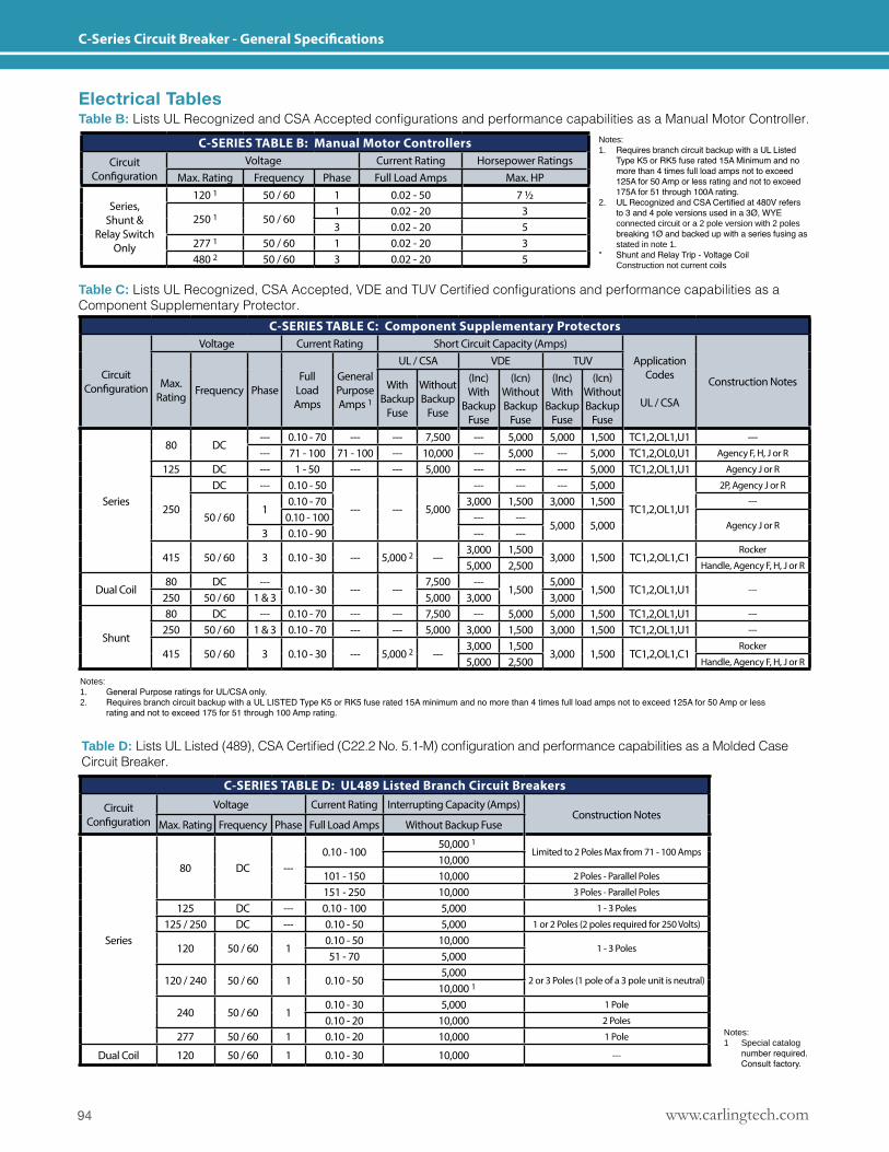
www.carlingtech.com94
C-Series Circuit Breaker - General Specifications
Electrical TablesTable B:ListsULRecognizedandCSAAcceptedconfigurationsandperformancecapabilitiesasaManualMotorController.
Table C:ListsULRecognized,CSAAccepted,VDEandTUVCertifiedconfigurationsandperformancecapabilitiesasaComponent Supplementary Protector.
Notes:1. Requires branch circuit backup with a UL Listed Type K5 or RK5 fuse rated 15A Minimum and no more than 4 times full load amps not to exceed 125A for 50 Amp or less rating and not to exceed 175A for 51 through 100A rating.2. UL Recognized and CSA Certified at 480V refers to 3 and 4 pole versions used in a 3Ø, WYE connected circuit or a 2 pole version with 2 poles breaking 1Ø and backed up with a series fusing as stated in note 1.* Shunt and Relay Trip - Voltage Coil Construction not current coils
Notes:1 Special catalog number required. Consult factory.
Notes:1. General Purpose ratings for UL/CSA only.2. Requires branch circuit backup with a UL LISTED Type K5 or RK5 fuse rated 15A minimum and no more than 4 times full load amps not to exceed 125A for 50 Amp or less
rating and not to exceed 175 for 51 through 100 Amp rating.
Table D:ListsULListed(489),CSACertified(C22.2No.5.1-M)configurationandperformancecapabilitiesasaMoldedCaseCircuit Breaker.
C-SERIES TABLE B: Manual Motor ControllersCircuit
ConfigurationVoltage Current Rating Horsepower Ratings
Max. Rating Frequency Phase Full Load Amps Max. HP
Series, Shunt &
Relay Switch Only
120 1 50 / 60 1 0.02 - 50 7 1/2
250 1 50 / 601 0.02 - 20 33 0.02 - 20 5
277 1 50 / 60 1 0.02 - 20 3480 2 50 / 60 3 0.02 - 20 5
C-SERIES TABLE C: Component Supplementary Protectors
Circuit Configuration
Voltage Current Rating Short Circuit Capacity (Amps)Application
Codes
UL / CSA
Construction NotesMax. Rating Frequency Phase
Full Load Amps
General Purpose Amps 1
UL / CSA VDE TUV
With Backup
Fuse
Without Backup
Fuse
(Inc)With
Backup Fuse
(Icn) Without Backup
Fuse
(Inc) With
Backup Fuse
(Icn) Without Backup
Fuse
Series
80 DC--- 0.10 - 70 --- --- 7,500 --- 5,000 5,000 1,500 TC1,2,OL1,U1 ------ 71 - 100 71 - 100 --- 10,000 --- 5,000 --- 5,000 TC1,2,OL0,U1 Agency F, H, J or R
125 DC --- 1 - 50 --- --- 5,000 --- --- --- 5,000 TC1,2,OL1,U1 Agency J or R
250
DC --- 0.10 - 50
--- --- 5,000
--- --- --- 5,000
TC1,2,OL1,U1
2P, Agency J or R
50 / 601
0.10 - 70 3,000 1,500 3,000 1,500 ---
0.10 - 100 --- ---5,000 5,000 Agency J or R
3 0.10 - 90 --- ---
415 50 / 60 3 0.10 - 30 --- 5,000 2 ---3,000 1,500
3,000 1,500 TC1,2,OL1,C1Rocker
5,000 2,500 Handle, Agency F, H, J or R
Dual Coil80 DC ---
0.10 - 30 --- ---7,500 ---
1,5005,000
1,500 TC1,2,OL1,U1 ---250 50 / 60 1 & 3 5,000 3,000 3,000
Shunt
80 DC --- 0.10 - 70 --- --- 7,500 --- 5,000 5,000 1,500 TC1,2,OL1,U1 ---
250 50 / 60 1 & 3 0.10 - 70 --- --- 5,000 3,000 1,500 3,000 1,500 TC1,2,OL1,U1 ---
415 50 / 60 3 0.10 - 30 --- 5,000 2 ---3,000 1,500
3,000 1,500 TC1,2,OL1,C1Rocker
5,000 2,500 Handle, Agency F, H, J or R
C-SERIES TABLE D: UL489 Listed Branch Circuit Breakers
Circuit Configuration
Voltage Current Rating Interrupting Capacity (Amps)Construction Notes
Max. Rating Frequency Phase Full Load Amps Without Backup Fuse
Series
80 DC ---0.10 - 100
50,000 1Limited to 2 Poles Max from 71 - 100 Amps
10,000101 - 150 10,000 2 Poles - Parallel Poles
151 - 250 10,000 3 Poles - Parallel Poles
125 DC --- 0.10 - 100 5,000 1 - 3 Poles
125 / 250 DC --- 0.10 - 50 5,000 1 or 2 Poles (2 poles required for 250 Volts)
120 50 / 60 10.10 - 50 10,000
1 - 3 Poles51 - 70 5,000
120 / 240 50 / 60 1 0.10 - 505,000
2 or 3 Poles (1 pole of a 3 pole unit is neutral)10,000 1
240 50 / 60 10.10 - 30 5,000 1 Pole
0.10 - 20 10,000 2 Poles
277 50 / 60 1 0.10 - 20 10,000 1 Pole
Dual Coil 120 50 / 60 1 0.10 - 30 10,000 ---
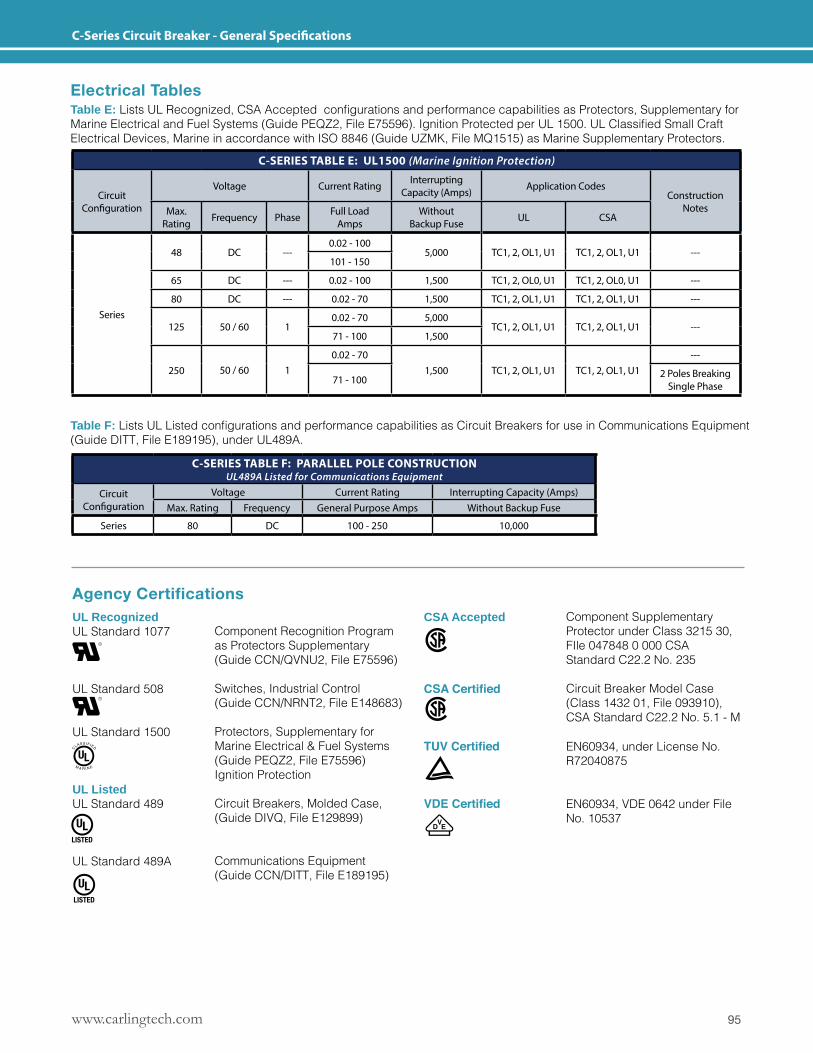
95www.carlingtech.com
C-Series Circuit Breaker - General Specifications
Electrical TablesTable E:ListsULRecognized,CSAAcceptedconfigurationsandperformancecapabilitiesasProtectors,SupplementaryforMarineElectricalandFuelSystems(GuidePEQZ2,FileE75596).IgnitionProtectedperUL1500.ULClassifiedSmallCraftElectrical Devices, Marine in accordance with ISO 8846 (Guide UZMK, File MQ1515) as Marine Supplementary Protectors.
Table F:ListsULListedconfigurationsandperformancecapabilitiesasCircuitBreakersforuseinCommunicationsEquipment(Guide DITT, File E189195), under UL489A.
Agency CertificationsUL RecognizedUL Standard 1077
UL Standard 508
UL Standard 1500
UL ListedUL Standard 489
UL Standard 489A
CSA Accepted
CSA Certified
TUV Certified
VDE Certified
Component Recognition Program as Protectors Supplementary (Guide CCN/QVNU2, File E75596)
Switches, Industrial Control (Guide CCN/NRNT2, File E148683)
Protectors, Supplementary for Marine Electrical & Fuel Systems (Guide PEQZ2, File E75596) Ignition Protection
Circuit Breakers, Molded Case, (Guide DIVQ, File E129899)
Communications Equipment (Guide CCN/DITT, File E189195)
Component Supplementary Protector under Class 3215 30, FIle 047848 0 000 CSA Standard C22.2 No. 235
Circuit Breaker Model Case (Class 1432 01, File 093910), CSA Standard C22.2 No. 5.1 - M
EN60934, under License No. R72040875
EN60934, VDE 0642 under File No. 10537
C-SERIES TABLE F: PARALLEL POLE CONSTRUCTIONUL489A Listed for Communications Equipment
Circuit Configuration
Voltage Current Rating Interrupting Capacity (Amps)Max. Rating Frequency General Purpose Amps Without Backup Fuse
Series 80 DC 100 - 250 10,000
C-SERIES TABLE E: UL1500 (Marine Ignition Protection)
Circuit Configuration
Voltage Current Rating Interrupting Capacity (Amps) Application Codes
Construction NotesMax.
Rating Frequency Phase Full Load Amps
Without Backup Fuse UL CSA
Series
48 DC ---0.02 - 100
5,000 TC1, 2, OL1, U1 TC1, 2, OL1, U1 ---101 - 150
65 DC --- 0.02 - 100 1,500 TC1, 2, OL0, U1 TC1, 2, OL0, U1 ---
80 DC --- 0.02 - 70 1,500 TC1, 2, OL1, U1 TC1, 2, OL1, U1 ---
125 50 / 60 10.02 - 70 5,000
TC1, 2, OL1, U1 TC1, 2, OL1, U1 ---71 - 100 1,500
250 50 / 60 10.02 - 70
1,500 TC1, 2, OL1, U1 TC1, 2, OL1, U1---
71 - 100 2 Poles Breaking Single Phase
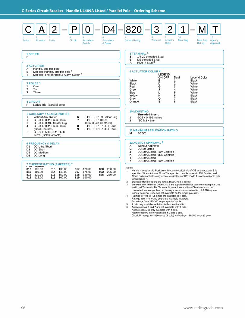
www.carlingtech.com96
C-Series Circuit Breaker - Handle UL489A Listed / Parallel Pole – Ordering Scheme
9 ACTUATOR COLOR 2 LEGEND ON-OFF Dual Legend ColorWhite B 1 BlackBlack D 2 WhiteRed G 3 WhiteGreen J 4 WhiteBlue L 5 WhiteYellow N 6 BlackGray Q 7 BlackOrange S 8 Black
10 MOUNTING Threaded Insert1 6-32 x 0.195 inches2 ISO M3 x 5mm
12 AGENCY APPROVAL 6A Without ApprovalG UL489 ListedJ UL489A Listed, TUV CertifiedK UL489A Listed, VDE Certified T UL489A Listed7 UL489A Listed, TUV Certified
1Series
2Actuator
3Poles
5Aux/Alarm Switch
6Frequency& Delay
7Current Rating
8Terminal
9ActuatorColor
10Mounting
11Max. App.Rating
12AgencyApproval
4 Circuit
C A P 3 12 0 2 M TD4 820
1 SERIESC
2 ACTUATORA Handle, one per poleS Mid-Trip Handle, one per pole 1T Mid-Trip, one per pole & Alarm Switch 1
8 TERMINAL 53 1/4-20 threaded Stud6 M6 threaded StudA Plug-In Stud 3
3 POLES 4 1 One 2 Two 3 Three
4 CIRCUITP Series Trip (parallel pole)
6 FREQUENCY & DELAYD1 DC Ultra ShortD2 DC ShortD4 DC MediumD6 DC Long
11 MAXIMUM APPLICATION RATINGM 80 DC
Notes:1 Handle moves to Mid-Position only upon electrical trip of C/B when Actuator S is specified. When Actuator Code T is specified, handle moves to Mid Position and Alarm Switch actuates only upon electrical trip of C/B. Code T is only available with Circuit Code N.2 Standard Handle colors are White, Black, Red & Yellow. 3 Breakers with Terminal Codes 3 & 6 are supplied with bus bars connecting the Line and Load Terminals. For Terminal Code A, Line and Load Terminals must be connected to a copper bus bar having a minimum cross-section of 0.078 square inches. Terminal Code A is not available on the single pole unit.4 Ratings for 101 to 125 amps are available in 1-pole. Ratings from 110 to 200 amps are available in 2-pole. For ratings from 225-300 amps, specify 3-pole.5 1 pole only available with terminal codes 3 and 6.6 Agency codes K and 7 are not available with 1 pole. Agency code J is only available with 1 pole. Agency code G is only available in 2 and 3 pole. Circuit P, ratings 101-150 amps (2 pole) and ratings 151-250 amps (3 pole).
5 AUXILIARY / ALARM SWITCH0 without Aux Switch2 S.P.D.T., 0.110 Q.C. Term.3 S.P.D.T., 0.139 Solder Lug4 S.P.D.T., 0.110 Q.C. Term. (Gold Contacts)5 S.P.S.T., N.O., 0.110 Q.C Term. (Gold Contacts)
6 S.P.S.T., 0.139 Solder Lug7 S.P.S.T., 0.110 Q.C Term. (Gold Contacts)8 S.P.S.T., 0.187 Q.C. Term.9 S.P.D.T., 0.187 Q.C. Term.
7 CURRENT RATING (AMPERES) 4CODE AMPERES 810 100.00811 110.00812 120.00912 125.00
813 130.00814 140.00815 150.00816 160.00
817 170.00917 175.00818 180.00819 190.00
820 200.00922 225.00825 250.00
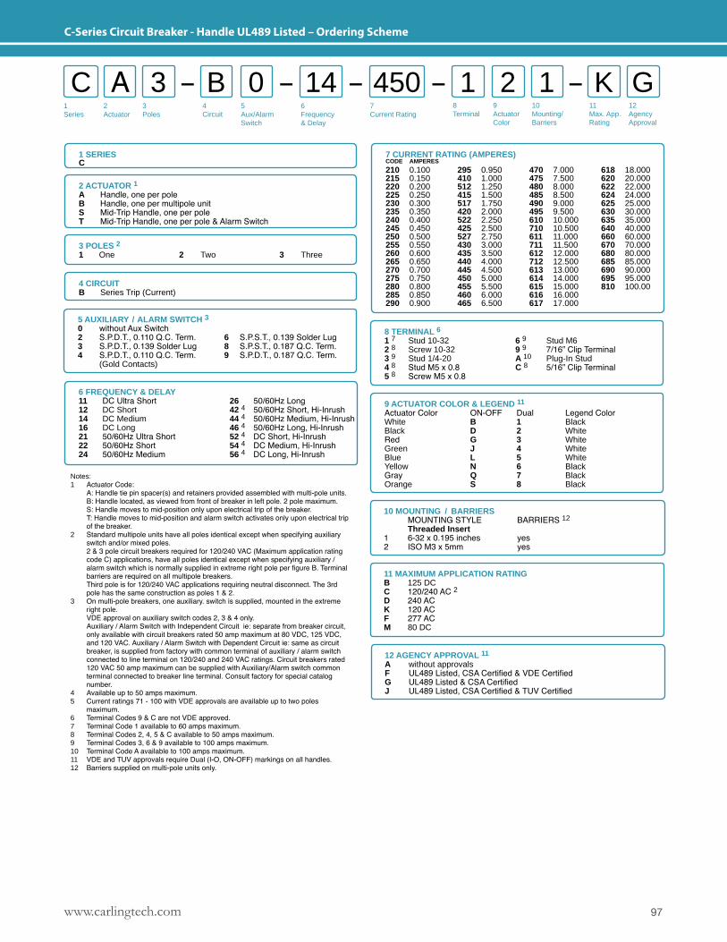
97www.carlingtech.com
C-Series Circuit Breaker - Handle UL489 Listed – Ordering Scheme
1Series
2Actuator
3Poles
5Aux/Alarm Switch
6Frequency& Delay
7Current Rating
8Terminal
9ActuatorColor
10Mounting/Barriers
11Max. App.Rating
12AgencyApproval
4 Circuit
C A B 1 13 0 2 K G14 450
11 MAXIMUM APPLICATION RATINGB 125 DCC 120/240 AC 2D 240 ACK 120 ACF 277 ACM 80 DC
Notes:1 Actuator Code: A: Handle tie pin spacer(s) and retainers provided assembled with multi-pole units. B: Handle located, as viewed from front of breaker in left pole. 2 pole maximum. S: Handle moves to mid-position only upon electrical trip of the breaker. T: Handle moves to mid-position and alarm switch activates only upon electrical trip of the breaker. 2 Standard multipole units have all poles identical except when specifying auxiliary switch and/or mixed poles. 2 & 3 pole circuit breakers required for 120/240 VAC (Maximum application rating code C) applications, have all poles identical except when specifying auxiliary / alarm switch which is normally supplied in extreme right pole per figure B. Terminal barriers are required on all multipole breakers. Third pole is for 120/240 VAC applications requiring neutral disconnect. The 3rd pole has the same construction as poles 1 & 2.3 On multi-pole breakers, one auxiliary. switch is supplied, mounted in the extreme right pole. VDE approval on auxiliary switch codes 2, 3 & 4 only. Auxiliary / Alarm Switch with Independent Circuit ie: separate from breaker circuit, only available with circuit breakers rated 50 amp maximum at 80 VDC, 125 VDC, and 120 VAC. Auxiliary / Alarm Switch with Dependent Circuit ie: same as circuit breaker, is supplied from factory with common terminal of auxiliary / alarm switch connected to line terminal on 120/240 and 240 VAC ratings. Circuit breakers rated 120 VAC 50 amp maximum can be supplied with Auxiliary/Alarm switch common terminal connected to breaker line terminal. Consult factory for special catalog number.4 Available up to 50 amps maximum. 5 Current ratings 71 - 100 with VDE approvals are available up to two poles maximum.6 Terminal Codes 9 & C are not VDE approved.7 Terminal Code 1 available to 60 amps maximum.8 Terminal Codes 2, 4, 5 & C available to 50 amps maximum.9 Terminal Codes 3, 6 & 9 available to 100 amps maximum.10 Terminal Code A available to 100 amps maximum.11 VDE and TUV approvals require Dual (I-O, ON-OFF) markings on all handles.12 Barriers supplied on multi-pole units only.
10 MOUNTING / BARRIERS MOUNTING STYLE BARRIERS 12 Threaded Insert1 6-32 x 0.195 inches yes2 ISO M3 x 5mm yes
12 AGENCY APPROVAL 11
A without approvalsF UL489 Listed, CSA Certified & VDE CertifiedG UL489 Listed & CSA CertifiedJ UL489 Listed, CSA Certified & TUV Certified
8 TERMINAL 61 7 Stud 10-32 6 9 Stud M62 8 Screw 10-32 9 9 7/16” Clip Terminal3 9 Stud 1/4-20 A 10 Plug-In Stud4 8 Stud M5 x 0.8 C 8 5/16” Clip Terminal5 8 Screw M5 x 0.8
5 AUXILIARY / ALARM SWITCH 30 without Aux Switch2 S.P.D.T., 0.110 Q.C. Term. 6 S.P.S.T., 0.139 Solder Lug3 S.P.D.T., 0.139 Solder Lug 8 S.P.S.T., 0.187 Q.C. Term.4 S.P.D.T., 0.110 Q.C. Term. 9 S.P.D.T., 0.187 Q.C. Term. (Gold Contacts)
6 FREQUENCY & DELAY11 DC Ultra Short12 DC Short14 DC Medium16 DC Long21 50/60Hz Ultra Short22 50/60Hz Short24 50/60Hz Medium
26 50/60Hz Long42 4 50/60Hz Short, Hi-Inrush44 4 50/60Hz Medium, Hi-Inrush46 4 50/60Hz Long, Hi-Inrush52 4 DC Short, Hi-Inrush54 4 DC Medium, Hi-Inrush56 4 DC Long, Hi-Inrush
9 ACTUATOR COLOR & LEGEND 11
Actuator Color ON-OFF Dual Legend ColorWhite B 1 Black Black D 2 WhiteRed G 3 WhiteGreen J 4 WhiteBlue L 5 WhiteYellow N 6 BlackGray Q 7 BlackOrange S 8 Black
1 SERIESC
2 ACTUATOR 1A Handle, one per poleB Handle, one per multipole unitS Mid-Trip Handle, one per poleT Mid-Trip Handle, one per pole & Alarm Switch
3 POLES 2 1 One 2 Two 3 Three
4 CIRCUITB Series Trip (Current)
7 CURRENT RATING (AMPERES)CODE AMPERES
210 0.100215 0.150220 0.200225 0.250230 0.300235 0.350240 0.400245 0.450250 0.500255 0.550260 0.600265 0.650270 0.700275 0.750280 0.800285 0.850290 0.900
295 0.950410 1.000512 1.250415 1.500517 1.750420 2.000522 2.250425 2.500 527 2.750430 3.000435 3.500440 4.000445 4.500450 5.000455 5.500460 6.000465 6.500
470 7.000475 7.500480 8.000485 8.500490 9.000495 9.500610 10.000710 10.500611 11.000711 11.500612 12.000712 12.500613 13.000614 14.000615 15.000616 16.000617 17.000
618 18.000620 20.000622 22.000624 24.000625 25.000630 30.000635 35.000640 40.000660 60.000670 70.000680 80.000685 85.000690 90.000695 95.000810 100.00
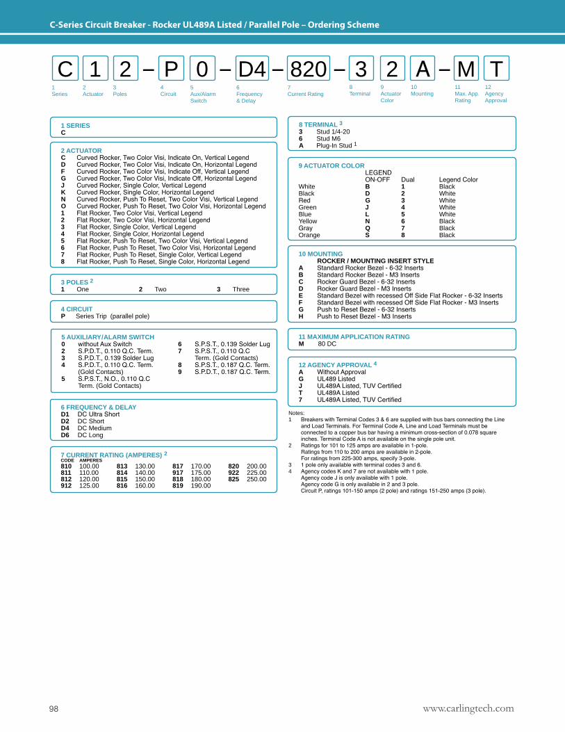
www.carlingtech.com98
C-Series Circuit Breaker - Rocker UL489A Listed / Parallel Pole – Ordering Scheme
9 ACTUATOR COLOR LEGEND ON-OFF Dual Legend ColorWhite B 1 BlackBlack D 2 WhiteRed G 3 WhiteGreen J 4 WhiteBlue L 5 WhiteYellow N 6 BlackGray Q 7 BlackOrange S 8 Black
10 MOUNTING ROCKER / MOUNTING INSERT STYLE A Standard Rocker Bezel - 6-32 InsertsB Standard Rocker Bezel - M3 InsertsC Rocker Guard Bezel - 6-32 InsertsD Rocker Guard Bezel - M3 InsertsE Standard Bezel with recessed Off Side Flat Rocker - 6-32 InsertsF Standard Bezel with recessed Off Side Flat Rocker - M3 InsertsG Push to Reset Bezel - 6-32 InsertsH Push to Reset Bezel - M3 Inserts
12 AGENCY APPROVAL 4A Without ApprovalG UL489 ListedJ UL489A Listed, TUV CertifiedT UL489A Listed7 UL489A Listed, TUV Certified
1Series
2Actuator
3Poles
5Aux/Alarm Switch
6Frequency& Delay
7Current Rating
8Terminal
9ActuatorColor
10Mounting
11Max. App.Rating
12AgencyApproval
4 Circuit
C 1 P 3 A2 0 2 M TD4 820
1 SERIESC
2 ACTUATORC Curved Rocker, Two Color Visi, Indicate On, Vertical LegendD Curved Rocker, Two Color Visi, Indicate On, Horizontal LegendF Curved Rocker, Two Color Visi, Indicate Off, Vertical LegendG Curved Rocker, Two Color Visi, Indicate Off, Horizontal LegendJ Curved Rocker, Single Color, Vertical LegendK Curved Rocker, Single Color, Horizontal LegendN Curved Rocker, Push To Reset, Two Color Visi, Vertical LegendO Curved Rocker, Push To Reset, Two Color Visi, Horizontal Legend1 Flat Rocker, Two Color Visi, Vertical Legend2 Flat Rocker, Two Color Visi, Horizontal Legend3 Flat Rocker, Single Color, Vertical Legend4 Flat Rocker, Single Color, Horizontal Legend5 Flat Rocker, Push To Reset, Two Color Visi, Vertical Legend6 Flat Rocker, Push To Reset, Two Color Visi, Horizontal Legend7 Flat Rocker, Push To Reset, Single Color, Vertical Legend8 Flat Rocker, Push To Reset, Single Color, Horizontal Legend
8 TERMINAL 33 Stud 1/4-206 Stud M6A Plug-In Stud 1
3 POLES 2 1 One 2 Two 3 Three
4 CIRCUITP Series Trip (parallel pole)
6 FREQUENCY & DELAYD1 DC Ultra ShortD2 DC ShortD4 DC MediumD6 DC Long
11 MAXIMUM APPLICATION RATINGM 80 DC
Notes:1 Breakers with Terminal Codes 3 & 6 are supplied with bus bars connecting the Line and Load Terminals. For Terminal Code A, Line and Load Terminals must be connected to a copper bus bar having a minimum cross-section of 0.078 square inches. Terminal Code A is not available on the single pole unit.2 Ratings for 101 to 125 amps are available in 1-pole. Ratings from 110 to 200 amps are available in 2-pole. For ratings from 225-300 amps, specify 3-pole.3 1 pole only available with terminal codes 3 and 6.4 Agency codes K and 7 are not available with 1 pole. Agency code J is only available with 1 pole. Agency code G is only available in 2 and 3 pole. Circuit P, ratings 101-150 amps (2 pole) and ratings 151-250 amps (3 pole).
5 AUXILIARY/ALARM SWITCH0 without Aux Switch2 S.P.D.T., 0.110 Q.C. Term.3 S.P.D.T., 0.139 Solder Lug4 S.P.D.T., 0.110 Q.C. Term. (Gold Contacts)5 S.P.S.T., N.O., 0.110 Q.C Term. (Gold Contacts)
6 S.P.S.T., 0.139 Solder Lug7 S.P.S.T., 0.110 Q.C Term. (Gold Contacts)8 S.P.S.T., 0.187 Q.C. Term.9 S.P.D.T., 0.187 Q.C. Term.
7 CURRENT RATING (AMPERES) 2CODE AMPERES 810 100.00811 110.00812 120.00912 125.00
813 130.00814 140.00815 150.00816 160.00
817 170.00917 175.00818 180.00819 190.00
820 200.00922 225.00825 250.00
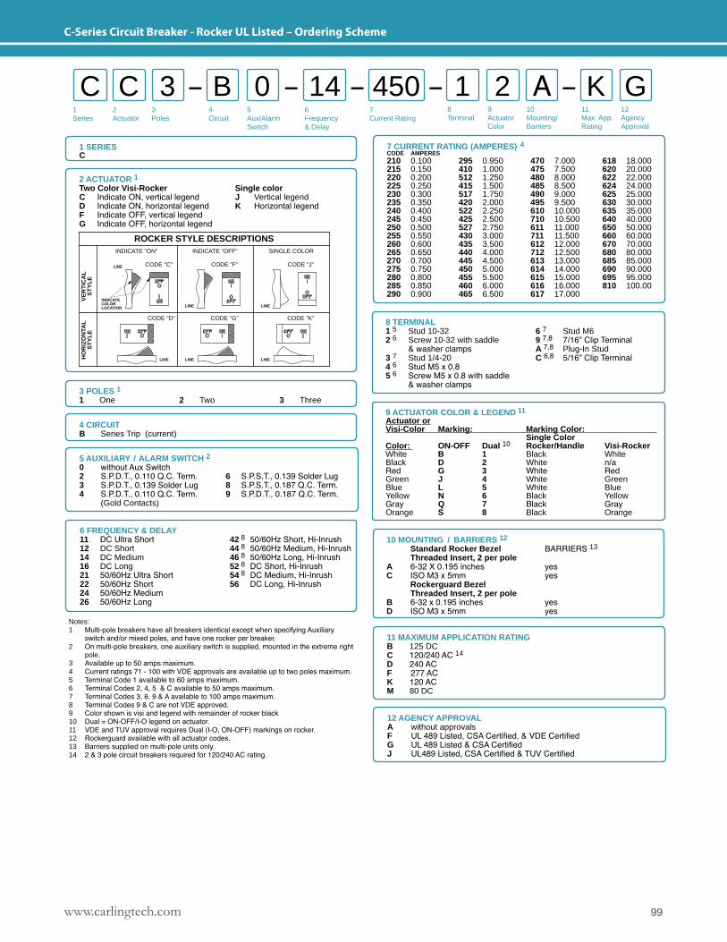
99www.carlingtech.com
C-Series Circuit Breaker - Rocker UL Listed – Ordering Scheme
8 TERMINAL1 5 Stud 10-32 6 7 Stud M62 6 Screw 10-32 with saddle 9 7,8 7/16” Clip Terminal & washer clamps A 7,8 Plug-In Stud3 7 Stud 1/4-20 C 6,8 5/16” Clip Terminal4 6 Stud M5 x 0.8 5 6 Screw M5 x 0.8 with saddle & washer clamps
9 ACTUATOR COLOR & LEGEND 11
Actuator orVisi-Color Marking: Marking Color: Single ColorColor: ON-OFF Dual 10 Rocker/Handle Visi-Rocker White B 1 Black WhiteBlack D 2 White n/aRed G 3 White RedGreen J 4 White GreenBlue L 5 White BlueYellow N 6 Black YellowGray Q 7 Black GrayOrange S 8 Black Orange
2 ACTUATOR 1Two Color Visi-Rocker Single colorC Indicate ON, vertical legend J Vertical legendD Indicate ON, horizontal legend K Horizontal legendF Indicate OFF, vertical legendG Indicate OFF, horizontal legend
SINGLE COLOR
CODE "J"
LINE
CODE "K"
LINE
INDICATE "ON"
CODE "C"LINE
LINELINE
LINE
CODE "D"
INDICATECOLORLOCATION
HO
RIZ
ON
TAL
ST
YL
EV
ER
TIC
AL
ST
YL
E
CODE "G"
CODE "F"
ROCKER STYLE DESCRIPTIONSINDICATE "OFF"
1Series
2Actuator
3Poles
5Aux/Alarm Switch
6Frequency& Delay
7Current Rating
8Terminal
9ActuatorColor
10Mounting/Barriers
11Max. App.Rating
12AgencyApproval
4 Circuit
C C B 1 A3 0 2 K G14 450
1 SERIESC
3 POLES 11 One 2 Two 3 Three
4 CIRCUITB Series Trip (current)
11 MAXIMUM APPLICATION RATINGB 125 DCC 120/240 AC 14
D 240 ACF 277 ACK 120 ACM 80 DC
6 FREQUENCY & DELAY11 DC Ultra Short12 DC Short14 DC Medium16 DC Long21 50/60Hz Ultra Short22 50/60Hz Short24 50/60Hz Medium26 50/60Hz Long
42 8 50/60Hz Short, Hi-Inrush44 8 50/60Hz Medium, Hi-Inrush46 8 50/60Hz Long, Hi-Inrush52 8 DC Short, Hi-Inrush54 8 DC Medium, Hi-Inrush56 DC Long, Hi-Inrush
Notes:1 Multi-pole breakers have all breakers identical except when specifying Auxiliary switch and/or mixed poles, and have one rocker per breaker.2 On multi-pole breakers, one auxiliary switch is supplied, mounted in the extreme right pole.3 Available up to 50 amps maximum. 4 Current ratings 71 - 100 with VDE approvals are available up to two poles maximum.5 Terminal Code 1 available to 60 amps maximum.6 Terminal Codes 2, 4, 5 & C available to 50 amps maximum.7 Terminal Codes 3, 6, 9 & A available to 100 amps maximum.8 Terminal Codes 9 & C are not VDE approved.9 Color shown is visi and legend with remainder of rocker black10 Dual = ON-OFF/I-O legend on actuator.11 VDE and TUV approval requires Dual (I-O, ON-OFF) markings on rocker.12 Rockerguard available with all actuator codes. 13 Barriers supplied on multi-pole units only.14 2 & 3 pole circuit breakers required for 120/240 AC rating.
10 MOUNTING / BARRIERS 12
Standard Rocker Bezel BARRIERS 13
Threaded Insert, 2 per poleA 6-32 X 0.195 inches yesC ISO M3 x 5mm yes Rockerguard Bezel Threaded Insert, 2 per poleB 6-32 x 0.195 inches yesD ISO M3 x 5mm yes
12 AGENCY APPROVALA without approvalsF UL 489 Listed, CSA Certified, & VDE CertifiedG UL 489 Listed & CSA CertifiedJ UL489 Listed, CSA Certified & TUV Certified
5 AUXILIARY / ALARM SWITCH 20 without Aux Switch2 S.P.D.T., 0.110 Q.C. Term. 6 S.P.S.T., 0.139 Solder Lug3 S.P.D.T., 0.139 Solder Lug 8 S.P.S.T., 0.187 Q.C. Term.4 S.P.D.T., 0.110 Q.C. Term. 9 S.P.D.T., 0.187 Q.C. Term. (Gold Contacts)
7 CURRENT RATING (AMPERES) 4CODE AMPERES 210 0.100215 0.150220 0.200225 0.250230 0.300235 0.350240 0.400245 0.450250 0.500255 0.550260 0.600265 0.650270 0.700275 0.750280 0.800285 0.850290 0.900
295 0.950410 1.000512 1.250415 1.500517 1.750420 2.000522 2.250425 2.500 527 2.750430 3.000435 3.500440 4.000445 4.500450 5.000455 5.500460 6.000465 6.500
470 7.000475 7.500480 8.000485 8.500490 9.000495 9.500610 10.000710 10.500611 11.000711 11.500612 12.000712 12.500613 13.000614 14.000615 15.000616 16.000617 17.000
618 18.000620 20.000622 22.000624 24.000625 25.000630 30.000635 35.000640 40.000650 50.000660 60.000670 70.000680 80.000685 85.000690 90.000695 95.000810 100.00
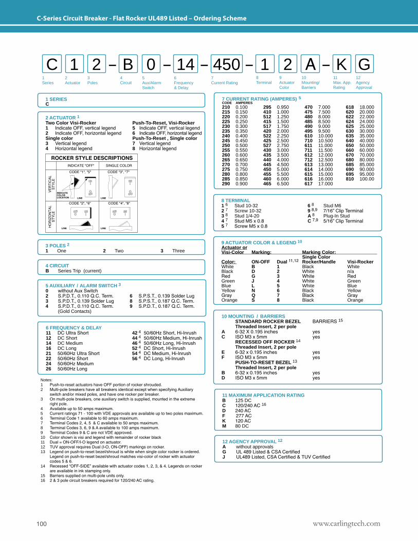
www.carlingtech.com100
C-Series Circuit Breaker - Flat Rocker UL489 Listed – Ordering Scheme
2 ACTUATOR 1Two Color Visi-Rocker Push-To-Reset, Visi-Rocker1 Indicate OFF, vertical legend 5 Indicate OFF, vertical legend2 Indicate OFF, horizontal legend 6 Indicate OFF, horizontal legendSingle color Push-To-Reset , Single color3 Vertical legend 7 Vertical legend4 Horizontal legend 8 Horizontal legend
1Series
2Actuator
3Poles
5Aux/Alarm Switch
6Frequency& Delay
7Current Rating
8Terminal
9ActuatorColor
10Mounting/Barriers
11Max. App.Rating
12AgencyApproval
4 Circuit
C 1 B 1 A2 0 2 K G14 450
1 SERIESC
Notes:1 Push-to-reset actuators have OFF portion of rocker shrouded.2 Multi-pole breakers have all breakers identical except when specifying Auxiliary switch and/or mixed poles, and have one rocker per breaker.3 On multi-pole breakers, one auxiliary switch is supplied, mounted in the extreme right pole.4 Available up to 50 amps maximum. 5 Current ratings 71 - 100 with VDE approvals are available up to two poles maximum.6 Terminal Code 1 available to 60 amps maximum.7 Terminal Codes 2, 4, 5 & C available to 50 amps maximum.8 Terminal Codes 3, 6, 9 & A available to 100 amps maximum.9 Terminal Codes 9 & C are not VDE approved.10 Color shown is visi and legend with remainder of rocker black11 Dual = ON-OFF/I-O legend on actuator.12 TUV approval requires Dual (I-O, ON-OFF) markings on rocker.13 Legend on push-to-reset bezel/shroud is white when single color rocker is ordered. Legend on push-to-reset bezel/shroud matches visi-color of rocker with actuator codes 5 & 6.14 Recessed “OFF-SIDE” available with actuator codes 1, 2, 3, & 4. Legends on rocker are available in ink stamping only.15 Barriers supplied on multi-pole units only.16 2 & 3 pole circuit breakers required for 120/240 AC rating.
10 MOUNTING / BARRIERS STANDARD ROCKER BEZEL BARRIERS 15
Threaded Insert, 2 per poleA 6-32 X 0.195 inches yesC ISO M3 x 5mm yes RECESSED OFF ROCKER 14
Threaded Insert, 2 per poleE 6-32 x 0.195 inches yesF ISO M3 x 5mm yes PUSH-TO-RESET BEZEL 13
Threaded Insert, 2 per poleB 6-32 x 0.195 inches yesD ISO M3 x 5mm yes
8 TERMINAL1 6 Stud 10-32 6 8 Stud M62 7 Screw 10-32 9 8,9 7/16” Clip Terminal3 8 Stud 1/4-20 A 8 Plug-In Stud4 7 Stud M5 x 0.8 C 7,9 5/16” Clip Terminal5 7 Screw M5 x 0.8
9 ACTUATOR COLOR & LEGEND 10
Actuator orVisi-Color Marking: Marking Color: Single ColorColor: ON-OFF Dual 11,12 Rocker/Handle Visi-Rocker White B 1 Black WhiteBlack D 2 White n/aRed G 3 White RedGreen J 4 White GreenBlue L 5 White BlueYellow N 6 Black YellowGray Q 7 Black GrayOrange S 8 Black Orange
3 POLES 21 One 2 Two 3 Three
4 CIRCUITB Series Trip (current)
11 MAXIMUM APPLICATION RATINGB 125 DCC 120/240 AC 16
D 240 ACF 277 ACK 120 ACM 80 DC
6 FREQUENCY & DELAY11 DC Ultra Short12 DC Short14 DC Medium16 DC Long21 50/60Hz Ultra Short22 50/60Hz Short24 50/60Hz Medium26 50/60Hz Long
42 4 50/60Hz Short, Hi-Inrush44 4 50/60Hz Medium, Hi-Inrush46 4 50/60Hz Long, Hi-Inrush52 4 DC Short, Hi-Inrush54 4 DC Medium, Hi-Inrush56 4 DC Long, Hi-Inrush
12 AGENCY APPROVAL 12
A without approvalsG UL 489 Listed & CSA CertifiedJ UL489 Listed, CSA Certified & TUV Certified
5 AUXILIARY / ALARM SWITCH 30 without Aux Switch2 S.P.D.T., 0.110 Q.C. Term. 6 S.P.S.T., 0.139 Solder Lug3 S.P.D.T., 0.139 Solder Lug 8 S.P.S.T., 0.187 Q.C. Term.4 S.P.D.T., 0.110 Q.C. Term. 9 S.P.D.T., 0.187 Q.C. Term. (Gold Contacts)
7 CURRENT RATING (AMPERES) 5CODE AMPERES 210 0.100215 0.150220 0.200225 0.250230 0.300235 0.350240 0.400245 0.450250 0.500255 0.550260 0.600265 0.650270 0.700275 0.750280 0.800285 0.850290 0.900
295 0.950410 1.000512 1.250415 1.500517 1.750420 2.000522 2.250425 2.500 527 2.750430 3.000435 3.500440 4.000445 4.500450 5.000455 5.500460 6.000465 6.500
470 7.000475 7.500480 8.000485 8.500490 9.000495 9.500610 10.000710 10.500611 11.000711 11.500612 12.000712 12.500613 13.000614 14.000615 15.000616 16.000617 17.000
618 18.000620 20.000622 22.000624 24.000625 25.000630 30.000635 35.000640 40.000650 50.000660 60.000670 70.000680 80.000685 85.000690 90.000695 95.000810 100.00
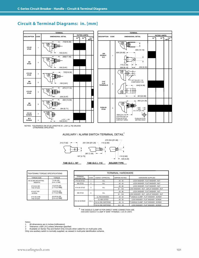
101www.carlingtech.com
C-Series Circuit Breaker - Handle – Circuit & Terminal Diagrams
.558 [14.17]
.960 [24.38]
.311 DIA [Ø7.90]
Notes: 1 All dimensions are in inches [millimeters].2 Tolerance ±.020 [.51] unless otherwise specified.3 Available on Series Trip and Switch Only Circuits when called for on multi-pole units. Only one auxiliary switch is normally supplied, as viewed in mulit-pole identification scheme.
Circuit & Terminal Diagrams: in. [mm]
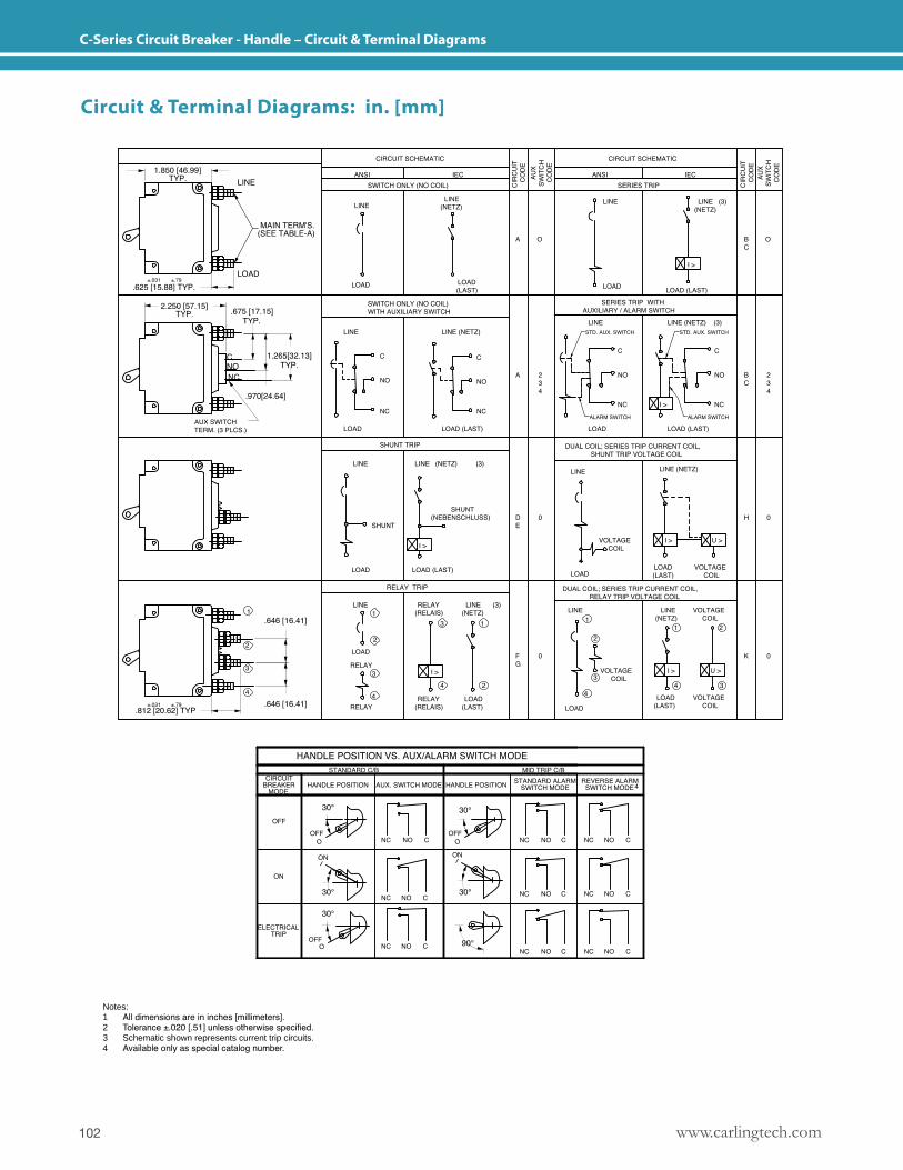
www.carlingtech.com102
C-Series Circuit Breaker - Handle – Circuit & Terminal Diagrams
Notes: 1 All dimensions are in inches [millimeters].2 Tolerance ±.020 [.51] unless otherwise specified.3 Schematic shown represents current trip circuits.4 Available only as special catalog number.
Circuit & Terminal Diagrams: in. [mm]
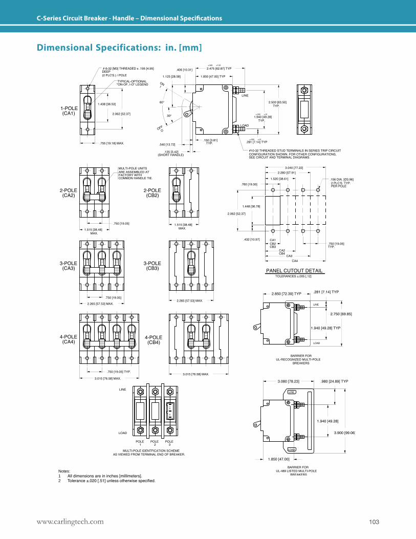
103www.carlingtech.com
C-Series Circuit Breaker - Handle – Dimensional Specifications
Notes: 1 All dimensions are in inches [millimeters].2 Tolerance ±.020 [.51] unless otherwise specified.
Dimensional Specifications: in. [mm]
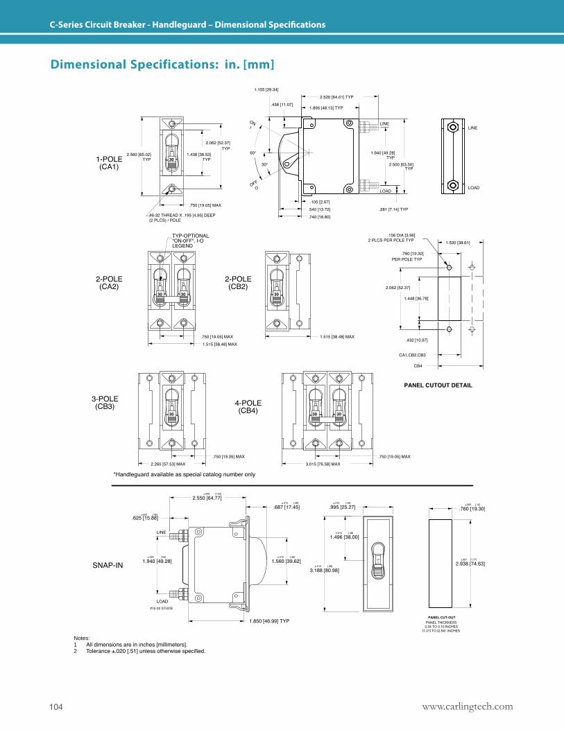
www.carlingtech.com104
C-Series Circuit Breaker - Handleguard – Dimensional Specifications
Notes: 1 All dimensions are in inches [millimeters].2 Tolerance ±.020 [.51] unless otherwise specified.
Dimensional Specifications: in. [mm]
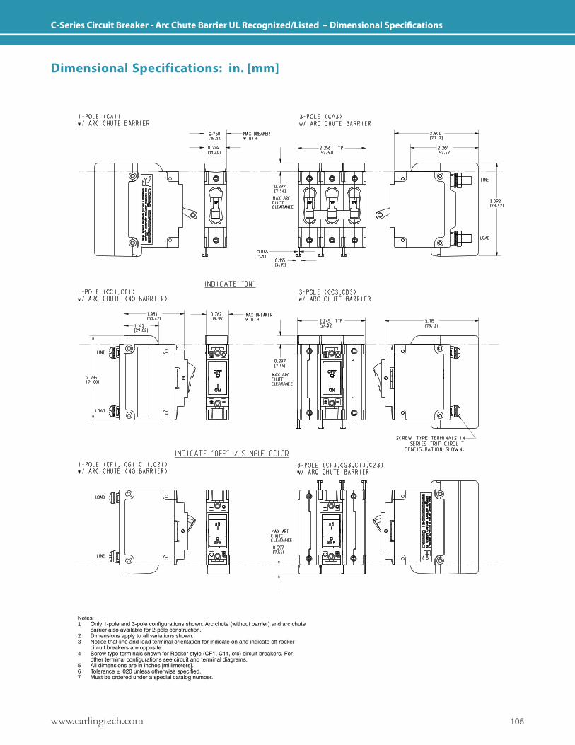
105www.carlingtech.com
C-Series Circuit Breaker - Arc Chute Barrier UL Recognized/Listed – Dimensional Specifications
Notes: 1 Only 1-pole and 3-pole configurations shown. Arc chute (without barrier) and arc chute barrier also available for 2-pole construction.2 Dimensions apply to all variations shown.3 Notice that line and load terminal orientation for indicate on and indicate off rocker circuit breakers are opposite.4 Screw type terminals shown for Rocker style (CF1, C11, etc) circuit breakers. For other terminal configurations see circuit and terminal diagrams.5 All dimensions are in inches [millimeters].6 Tolerance ± .020 unless otherwise specified.7 Must be ordered under a special catalog number.
Dimensional Specifications: in. [mm]
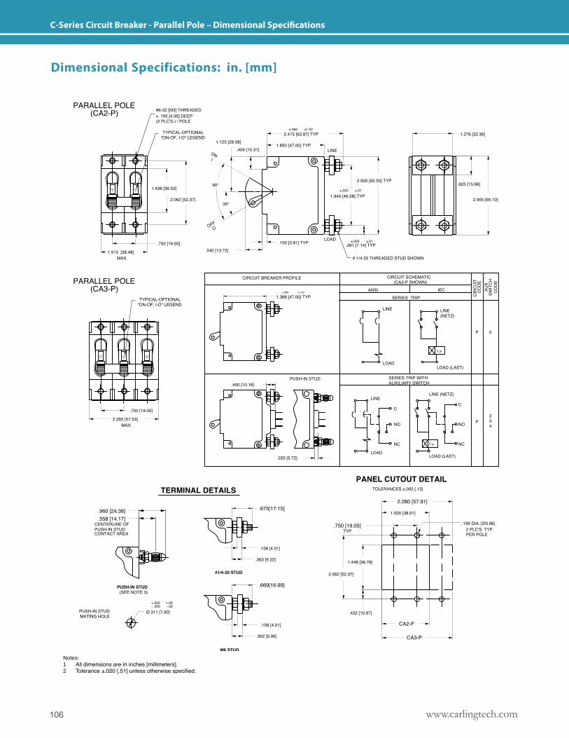
www.carlingtech.com106
C-Series Circuit Breaker - Parallel Pole – Dimensional Specifications
Notes: 1 All dimensions are in inches [millimeters].2 Tolerance ±.020 [.51] unless otherwise specified.
Dimensional Specifications: in. [mm]
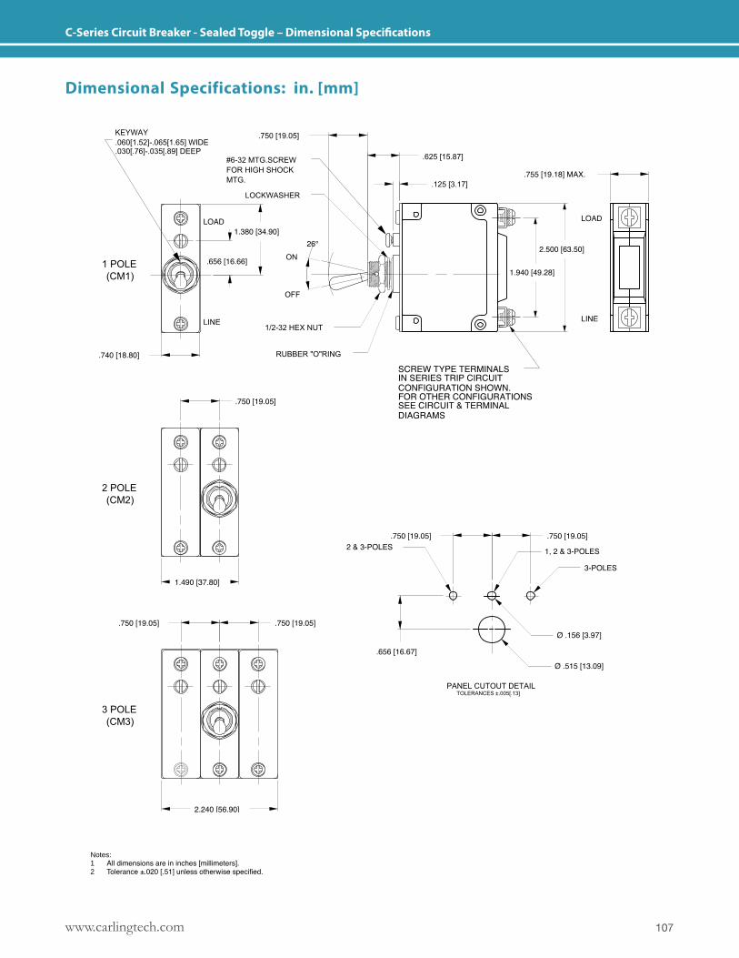
107www.carlingtech.com
C-Series Circuit Breaker - Sealed Toggle – Dimensional Specifications
Notes: 1 All dimensions are in inches [millimeters].2 Tolerance ±.020 [.51] unless otherwise specified.
Dimensional Specifications: in. [mm]
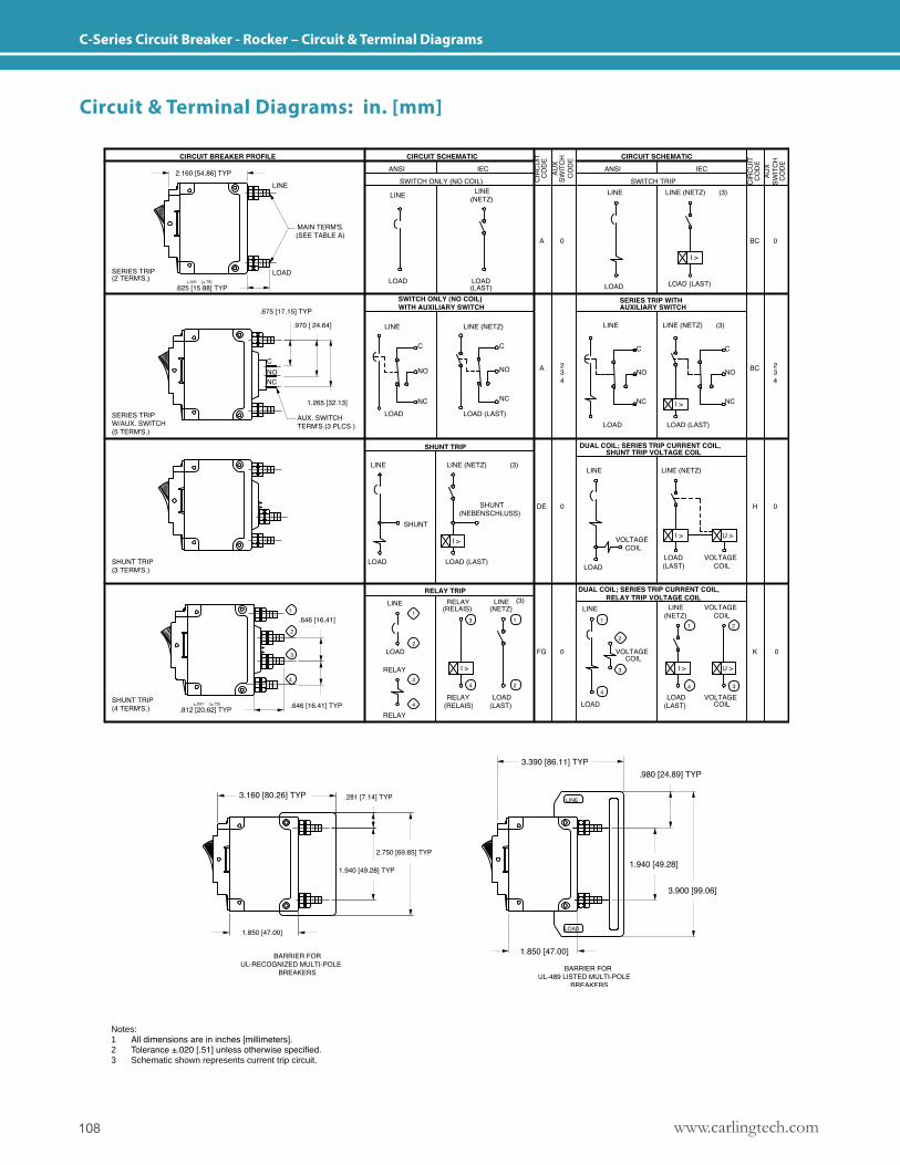
www.carlingtech.com108
C-Series Circuit Breaker - Rocker – Circuit & Terminal Diagrams
Notes: 1 All dimensions are in inches [millimeters].2 Tolerance ±.020 [.51] unless otherwise specified.3 Schematic shown represents current trip circuit.
Circuit & Terminal Diagrams: in. [mm]
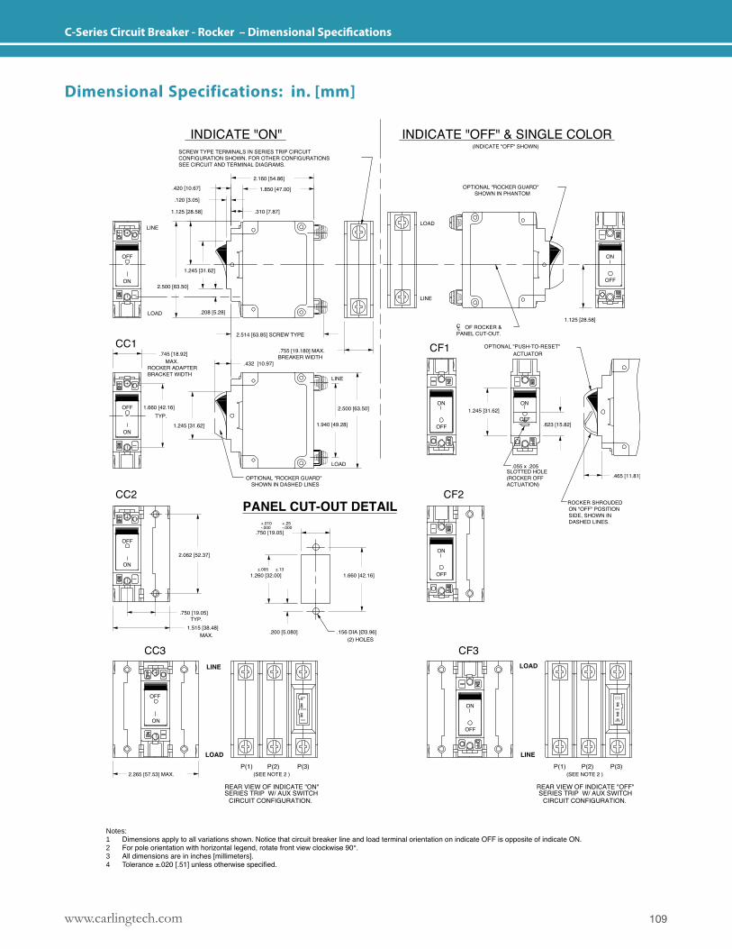
109www.carlingtech.com
C-Series Circuit Breaker - Rocker – Dimensional Specifications
Notes: 1 Dimensions apply to all variations shown. Notice that circuit breaker line and load terminal orientation on indicate OFF is opposite of indicate ON.2 For pole orientation with horizontal legend, rotate front view clockwise 90°.3 All dimensions are in inches [millimeters].4 Tolerance ±.020 [.51] unless otherwise specified.
Dimensional Specifications: in. [mm]
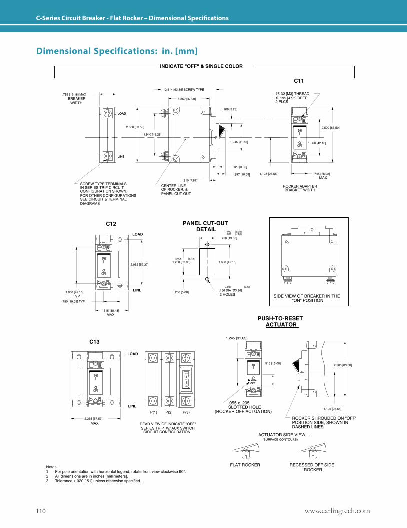
www.carlingtech.com110
C-Series Circuit Breaker - Flat Rocker – Dimensional Specifications
Notes: 1 For pole orientation with horizontal legend, rotate front view clockwise 90°.2 All dimensions are in inches [millimeters].3 Tolerance ±.020 [.51] unless otherwise specified.
Dimensional Specifications: in. [mm]
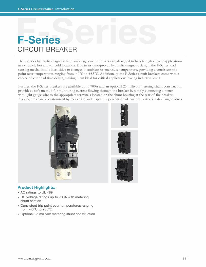
111www.carlingtech.com
F-Series Circuit Breaker - Introduction
F-SeriesF-SeriesCIRCUIT BREAKERThe F-Series hydraulic-magnetic high amperage circuit breakers are designed to handle high current applications in extremely hot and/or cold locations. Due to its time-proven hydraulic-magnetic design, the F-Series load sensing mechanism is insensitive to changes in ambient or enclosure temperature, providing a consistent trip point over temperatures ranging from -40°C to +85°C. Additionally, the F-Series circuit breakers come with a choice of overload time delays, making them ideal for critical applications having inductive loads.
Further, the F-Series breakers are available up to 700A and an optional 25 millivolt metering shunt construction provides a safe method for monitoring current flowing through the breaker by simply connecting a meter with light gauge wire to the appropriate terminals located on the shunt housing at the rear of the breaker. Applications can be customized by measuring and displaying percentage of current, watts or safe/danger zones.
Product Highlights: � AC ratings to UL 489 � DC voltage ratings up to 700A with metering shunt section
� Consistent trip point over temperatures ranging from -40°C to +85°C
� Optional 25 millivolt metering shunt construction
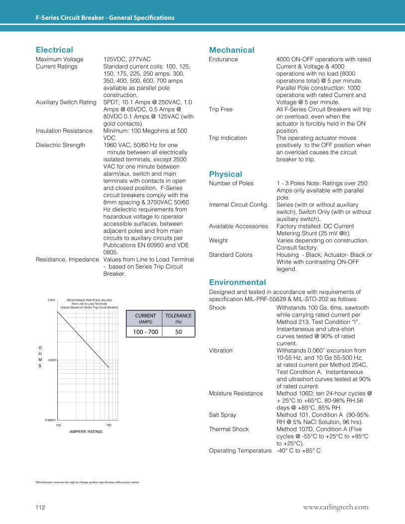
www.carlingtech.com112
F-Series Circuit Breaker - General Specifications
*Manufacturer reserves the right to change product specification without prior notice.
RESISTANCE PER POLE VALUESfrom Line to Load Terminals
(Values Based on Series Trip Circuit Breaker)
Mechanical
Physical
Environmental
Electrical
Designed and tested in accordance with requirements of specificationMIL-PRF-55629&MIL-STD-202asfollows:
Maximum Voltage 125VDC, 277VAC Current Ratings Standard current coils: 100, 125, 150, 175, 225, 250 amps. 300, 350, 400, 500, 600, 700 amps available as parallel pole construction.Auxiliary Switch Rating SPDT; 10.1 Amps @ 250VAC, 1.0 Amps @ 65VDC, 0.5 Amps @ 80VDC 0.1 Amps @ 125VAC (with gold contacts).Insulation Resistance Minimum: 100 Megohms at 500 VDCDielectric Strength 1960 VAC, 50/60 Hz for one minute between all electrically isolated terminals, except 2500 VAC for one minute between alarm/aux. switch and main terminals with contacts in open and closed position. F-Series circuit breakers comply with the 8mm spacing & 3750VAC 50/60 Hz dielectric requirements from hazardous voltage to operator accessible surfaces, between adjacent poles and from main circuits to auxilary circuits per Publications EN 60950 and VDE 0805.Resistance, Impedance Values from Line to Load Terminal - based on Series Trip Circuit Breaker.
Endurance 4000 ON-OFF operations with rated Current & Voltage & 4000 operations with no load (8000 operations total) @ 5 per minute. Parallel Pole construction: 1000 operations with rated Current and Voltage @ 5 per minute.Trip Free All F-Series Circuit Breakers will trip on overload, even when the actuator is forcibly held in the ON position.Trip Indication The operating actuator moves positively to the OFF position when an overload causes the circuit breaker to trip.
Number of Poles 1 - 3 Poles Note: Ratings over 250 Amps only available with parallel pole.InternalCircuitConfig. Series(withorwithoutauxiliary switch), Switch Only (with or without auxiliary switch).Available Accessories Factory installed: DC Current Metering Shunt (25 mV @lr)Weight Varies depending on construction. Consult factory.Standard Colors Housing - Black; Actuator- Black or White with contrasting ON-OFF legend.
Shock Withstands 100 Gs, 6ms, sawtooth while carrying rated current per Method 213, Test Condition “I”. Instantaneous and ultra-short curves tested @ 90% of rated current.Vibration Withstands 0.060” excursion from 10-55 Hz, and 10 Gs 55-500 Hz, at rated current per Method 204C, Test Condition A. Instantaneous and ultrashort curves tested at 90% of rated current.Moisture Resistance Method 106D; ten 24-hour cycles @ + 25°C to +65°C, 80-98% RH.56 days @ +85°C, 85% RH.Salt Spray Method 101, Condition A (90-95% RH @ 5% NaCl Solution, 96 hrs).Thermal Shock Method 107D, Condition A (Five cycles @ -55°C to +25°C to +85°C to +25°C).Operating Temperature -40° C to +85° C
CURRENT (AMPS)
TOLERANCE (%)
100 - 700 50
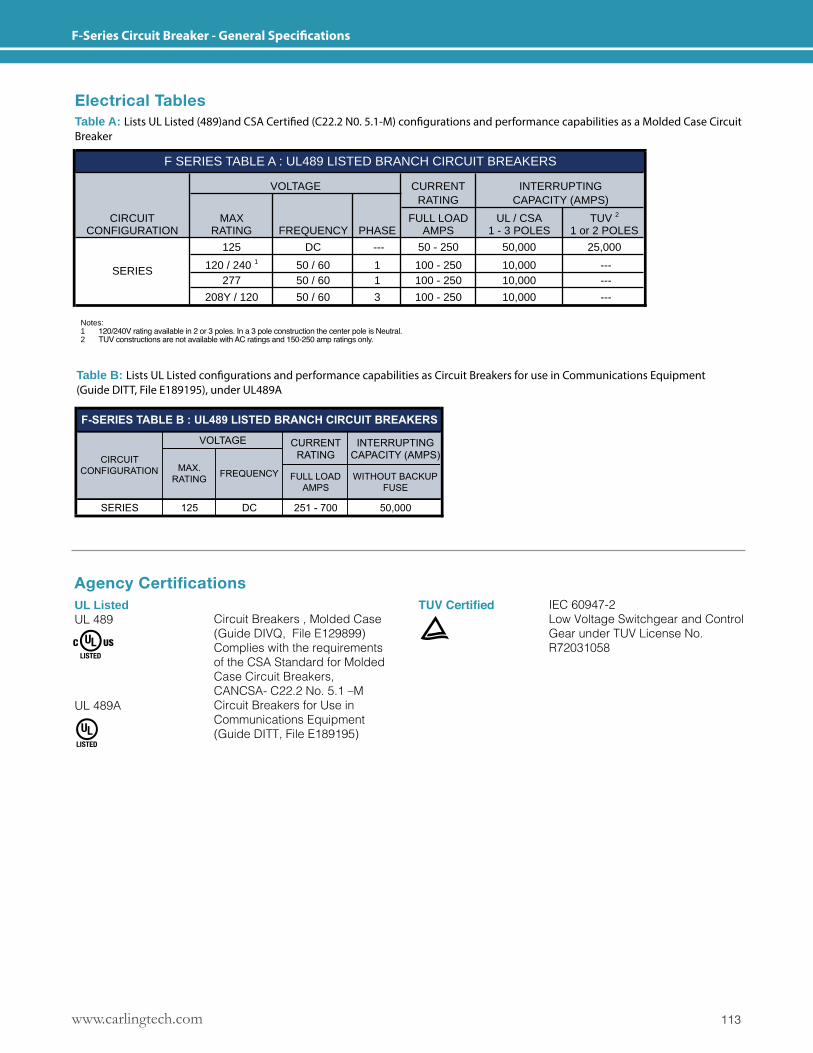
113www.carlingtech.com
F-Series Circuit Breaker - General Specifications
Table A: Lists UL Listed (489)and CSA Certified (C22.2 N0. 5.1-M) configurations and performancecapabilities as a Molded Case Circuit Brekaer
CURRENTRATING
CIRCUIT MAX FULL LOAD UL / CSA TUV 2
CONFIGURATION RATING FREQUENCY PHASE AMPS 1 - 3 POLES 1 or 2 POLES
125 DC --- 50 - 250 50,000 25,000
120 / 240 1 50 / 60 1 100 - 250 10,000 ---277 50 / 60 1 100 - 250 10,000 ---
208Y / 120 50 / 60 3 100 - 250 10,000 ---
NOTES: 1. 120/240V rating available in 2 or 3 poles. In a 3 pole construction the center pole is Neutral.2. TUV constructions are not available with AC ratings.
SERIES
F SERIES TABLE A : UL489 LISTED BRANCH CIRCUIT BREAKERS
VOLTAGE INTERRUPTINGCAPACITY (AMPS)
Electrical TablesTable A: Lists UL Listed (489)and CSA Certified (C22.2 N0. 5.1-M) configurations and performance capabilities as a Molded Case Circuit Breaker
Table B: Lists UL Listed configurations and performance capabilities as Circuit Breakers for use in Communications Equipment(Guide DITT, File E189195), under UL489A
Agency CertificationsUL ListedUL 489
UL 489A
TUV CertifiedCircuit Breakers , Molded Case (Guide DIVQ, File E129899)Complies with the requirements of the CSA Standard for Molded Case Circuit Breakers, CANCSA- C22.2 No. 5.1 –MCircuit Breakers for Use in Communications Equipment (Guide DITT, File E189195)
IEC 60947-2Low Voltage Switchgear and Control Gear under TUV License No. R72031058
Notes: 1 120/240V rating available in 2 or 3 poles. In a 3 pole construction the center pole is Neutral.2 TUV constructions are not available with AC ratings and 150-250 amp ratings only.
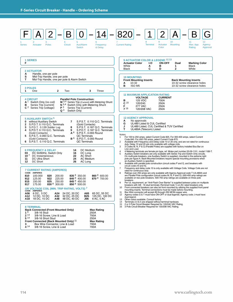
www.carlingtech.com114
F-Series Circuit Breaker - Handle – Ordering Scheme
1Series
2Actuator
3Poles
5Aux/Alarm Switch
6Frequency& Delay
7Current Rating
8Terminal
9ActuatorColor
10Mounting
11Max. App.Rating
12AgencyApproval
4 Circuit
F A B 1 A2 0 2 B G14 820
1 SERIESF
2 ACTUATORA Handle, one per poleS Mid-Trip Handle, one per poleT Mid-Trip Handle, one per pole & Alarm Switch
8 TERMINALBack Connected (Front Mounted Only) Max Rating 1 9 3/8-16 Stud 250A2 14 3/8-16 Screw, Line & Load 700A5 14 3/8-16 Short Stud 250AFront Connected (Back Mounted Only) 11 Max Rating3 Box Wire Connector, Line & Load 700A4 14 3/8-16 Screw, Line & Load 700A
10 MOUNTINGFront Mounting InsertsA 10-32B ISO M5
Back Mounting Inserts10-32 screw clearance holes10-32 screw clearance holes
3 POLES 1 One 2 Two 3 Three
6 FREQUENCY & DELAY03 DC 50/60Hz, Switch Only10 7 DC Instantaneous11 DC Ultra Short12 DC Short
14 DC Medium16 DC Long22 AC Short24 AC Medium26 AC Long
11 MAXIMUM APPLICATION RATING VOLTAGE CURRENTB 125 VDC 700AC 15 120/240 250AF 277 VAC 250A7 16 120/208 VAC 250A
12 AGENCY APPROVALA No approvalsG UL489 Listed & CUL CertifiedJ UL489 Listed, CUL Certified & TUV CertifiedT UL489A (Telecom) Listed
9 ACTUATOR COLOR & LEGEND 12,13
Actuator Color I-O ON-OFF Dual Marking ColorWhite A B 1 BlackBlack C D 2 White
Notes: 1 For 100 to 250 amps, select Current Code 825. For 300-400 amps, select Current Code 840. For 450-700 amps, select Current Code 870.2 Available with Frequency and Delay code 10 or 20 only, and are not rated for continuous duty. Delay 10 and 20 are only available with voltage coils.3 3 Codes M, N, P & Q (Parallel Poles) are supplied with factory installed Bus Bar on Line and Load.4 4 Metering terminals are female pin type, ref. Molex part number 02-09-1101, model 1189-T.5 Auxiliary Switch breakers are only available with Series Trip and Switch Only circuits. On multi-pole breakers, one Auxiliary Switch is supplied, mounted in the extreme right pole per figure A. Back-Mounted breakers require special mounting provisions when an Auxiliary Switch is specified.6 Available with parallel pole construction (circuit codes P and Q, and breakers with circuit codes M and N).7 Frequency and delay code 10 is only available with Voltage Coils. Voltage Coils are not rated for continuous duty.8 Ratings over 250 amps are only available with Agency Approval code T (UL489A) and are Parallel Pole configuration (circuit codes M, N, P and Q.) 300-450 amp ratings are available on two pole breakers. 500-700 amp ratings are available on three pole breakers.9 Per UL requirement, an “Anti-Flash Over Barrier” is supplied between poles on multipole breakers with 3/8 - 16 stud terminals (Terminal Code 1) on AC rated breakers only.10 Front connected breakers can also be front mounted by utilizing the supplied front panel mounting inserts. Terminal connections must be made before mounting.11 Box Wire connector will accept #6 through 250 MCM copper wire.12 Agency codes G & T must have ON-OFF or dual legends. Agency code J must have dual legend.13 Other colors available. Consult factory.14 Terminals 2,4 & 5 are shipped without terminal hardware.15 2 or 3 Pole Circuit Breaker Required for 120/240 VAC Rating.16 3 Pole Circuit Breaker Required for 120/208 VAC Rating.
4 CIRCUIT Parallel Pole Construction:A 1 Switch Only (no coil) M 3,4 Series Trip (Current) with Metering ShuntB Series Trip (current) N 3,4 Switch Only with Metering ShuntC 2 Series Trip (voltage) P 3 Series Trip (Current) Q 3 Switch Only
5 AUXILIARY SWITCH 50 without Auxiliary Switch 7 S.P.S.T. 0.110 Q.C. Terminals2 S.P.D.T. 0.110 Q.C. Terminals (Gold Contacts)3 S.P.D.T. 0.139 Solder Lug 8 S.P.S.T. 0.187 Q.C. Terminals4 S.P.D.T. 0.110 Q.C. Terminals 9 S.P.D.T. 0.187 Q.C. Terminals (Gold Contacts) A 6 S.P.S.T., 0.093 Round5 S.P.S.T., 0.093 Q.C. Terminals QC Terminals (Gold Contacts) B 6 S.P.D.T., 0.093 Round6 S.P.S.T. 0.110 Q.C. Terminals QC Terminals
7 CURRENT RATING (AMPERES)CODE AMPERES
OR VOLTAGE COIL (MIN. TRIP RATING, VOLTS) 7CODE AMPERES
810 100.000912 125.00815 150.00917 175.00
820 200.00922 225.00825 250.00830 8 300.00
835 8 350.00840 8 400.00845 8 450.00850 8 500.00
860 8 600.00870 8 700.00
A06 6 DC, 5 DCA12 12 DC, 10 DCA18 18 DC, 15 DC
A24 24 DC, 20 DCA32 32 DC, 25 DCA48 48 DC, 40 DC
A65 65 DC, 55 DCB25 125 DC, 100 DCJ06 6 AC, 5 AC
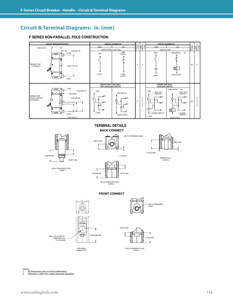
115www.carlingtech.com
F-Series Circuit Breaker - Handle – Circuit & Terminal Diagrams
Notes: 1 All dimensions are in inches [millimeters].2 Tolerance ±.020 [.51] unless otherwise specified.
Circuit & Terminal Diagrams: in. [mm]
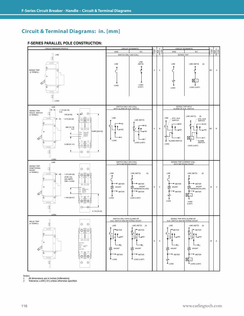
www.carlingtech.com116
F-Series Circuit Breaker - Handle – Circuit & Terminal Diagrams
Circuit & Terminal Diagrams: in. [mm]
Notes: 1 All dimensions are in inches [millimeters].2 Tolerance ±.020 [.51] unless otherwise specified.
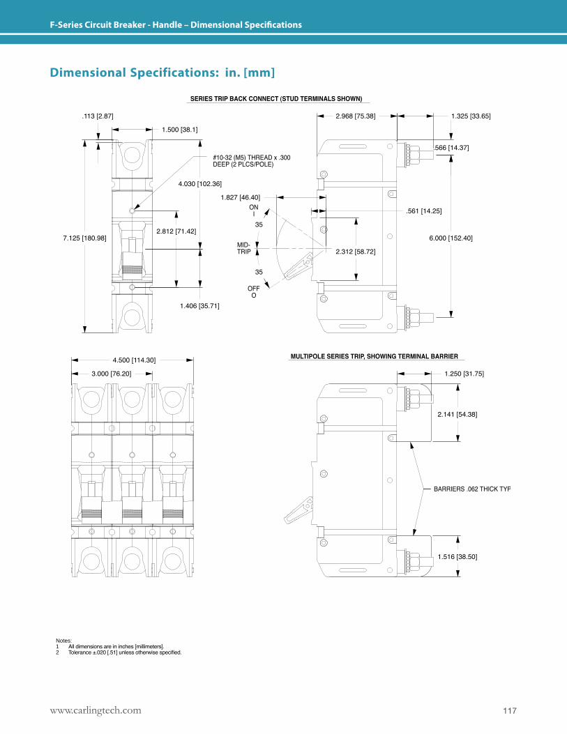
117www.carlingtech.com
F-Series Circuit Breaker - Handle – Dimensional Specifications
Dimensional Specifications: in. [mm]
Notes: 1 All dimensions are in inches [millimeters].2 Tolerance ±.020 [.51] unless otherwise specified.
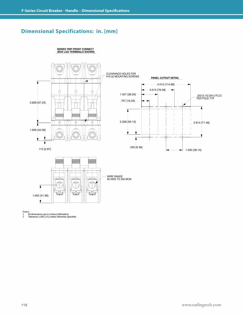
www.carlingtech.com118
F-Series Circuit Breaker - Handle – Dimensional Specifications
Dimensional Specifications: in. [mm]
Notes: 1 All dimensions are in inches [millimeters].2 Tolerance ±.020 [.51] unless otherwise specified.
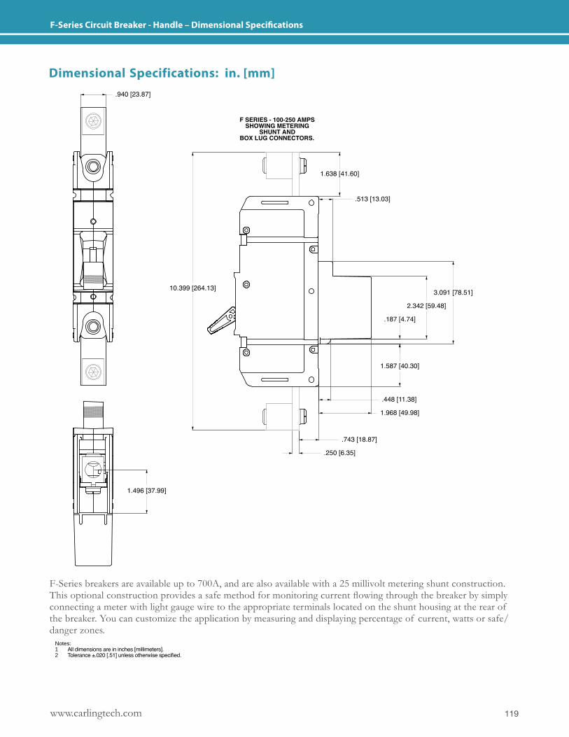
119www.carlingtech.com
F-Series Circuit Breaker - Handle – Dimensional Specifications
F-Series breakers are available up to 700A, and are also available with a 25 millivolt metering shunt construction. This optional construction provides a safe method for monitoring current flowing through the breaker by simply connecting a meter with light gauge wire to the appropriate terminals located on the shunt housing at the rear of the breaker. You can customize the application by measuring and displaying percentage of current, watts or safe/danger zones.
Dimensional Specifications: in. [mm]
Notes: 1 All dimensions are in inches [millimeters].2 Tolerance ±.020 [.51] unless otherwise specified.
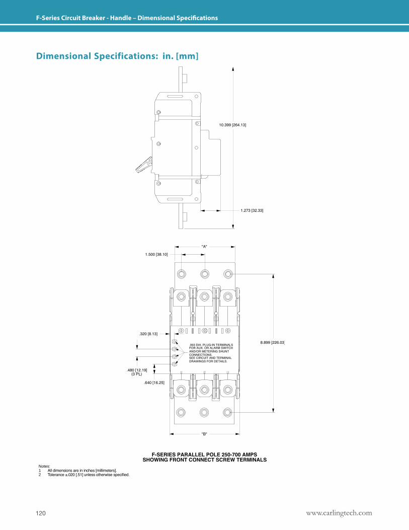
www.carlingtech.com120
F-Series Circuit Breaker - Handle – Dimensional Specifications
Dimensional Specifications: in. [mm]
Notes: 1 All dimensions are in inches [millimeters].2 Tolerance ±.020 [.51] unless otherwise specified.
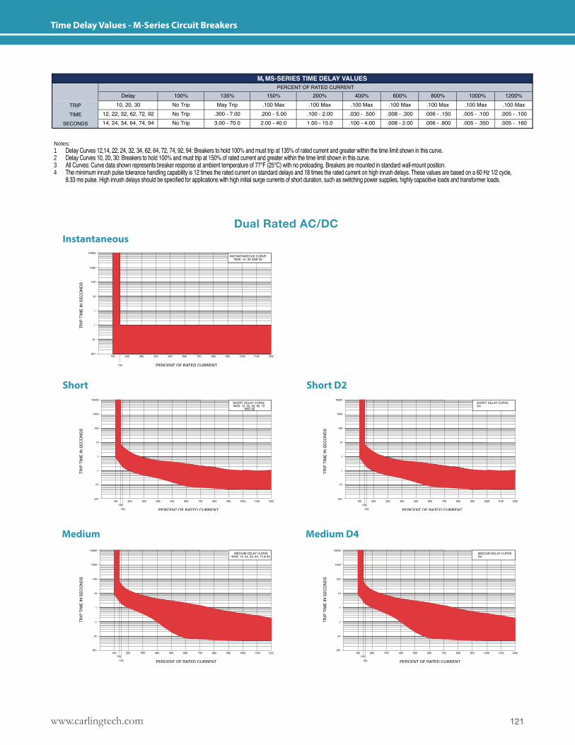
121www.carlingtech.com
Time Delay Values - M-Series Circuit Breakers
,
Notes: 1 Delay Curves 12,14, 22, 24, 32, 34, 62, 64, 72, 74, 92, 94: Breakers to hold 100% and must trip at 135% of rated current and greater within the time limit shown in this curve.2 Delay Curves 10, 20, 30: Breakers to hold 100% and must trip at 150% of rated current and greater within the time limit shown in this curve.3 All Curves: Curve data shown represents breaker response at ambient temperature of 77°F (25°C) with no preloading. Breakers are mounted in standard wall-mount position.4 The minimum inrush pulse tolerance handling capability is 12 times the rated current on standard delays and 18 times the rated current on high inrush delays. These values are based on a 60 Hz 1/2 cycle, 8.33 ms pulse. High inrush delays should be specified for applications with high initial surge currents of short duration, such as switching power supplies, highly capacitive loads and transformer loads.
Medium Medium D4
Instantaneous
Short Short D2
Dual Rated AC/DC
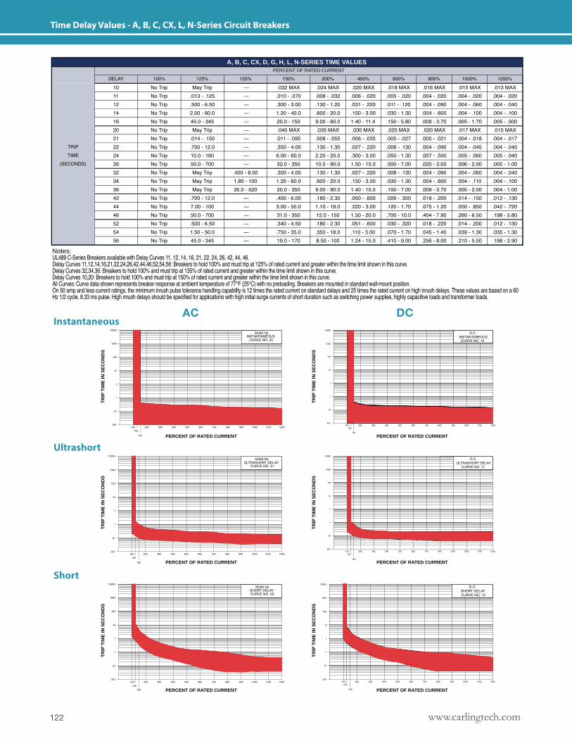
www.carlingtech.com122
Time Delay Values - A, B, C, CX, L, N-Series Circuit Breakers
PERCENT OF RATED CURRENT
A, B, C, CX, D, G, H, L, N-SERIES TIME VALUES
Notes: UL489 C-Series Breakers available with Delay Curves 11, 12, 14, 16, 21, 22, 24, 26, 42, 44, 46. Delay Curves 11,12,14,16,21,22,24,26,42,44,46,52,54,56: Breakers to hold 100% and must trip at 125% of rated current and greater within the time limit shown in this curve. Delay Curves 32,34,36: Breakers to hold 100% and must trip at 135% of rated current and greater within the time limit shown in this curve. Delay Curves 10,20: Breakers to hold 100% and must trip at 150% of rated current and greater within the time limit shown in this curve. All Curves: Curve data shown represents breaker response at ambient temperature of 77°F (25°C) with no preloading. Breakers are mounted in standard wall-mount position. On 50 amp and less current ratings, the minimum inrush pulse tolerance handling capability is 12 times the rated current on standard delays and 25 times the rated current on high inrush delays. These values are based on a 60 Hz 1/2 cycle, 8.33 ms pulse. High inrush delays should be specified for applications with high initial surge currents of short duration such as switching power supplies, highly capacitive loads and transformer loads.
Instantaneous
Ultrashort
Short
AC DCT
RIP
TIM
E IN
SE
CO
ND
S
PERCENT OF RATED CURRENT
TR
IP T
IME
IN S
EC
ON
DS
PERCENT OF RATED CURRENT
TR
IP T
IME
IN S
EC
ON
DS
PERCENT OF RATED CURRENT
TR
IP T
IME
IN S
EC
ON
DS
PERCENT OF RATED CURRENT
TR
IP T
IME
IN S
EC
ON
DS
PERCENT OF RATED CURRENT
TR
IP T
IME
IN S
EC
ON
DS
PERCENT OF RATED CURRENT
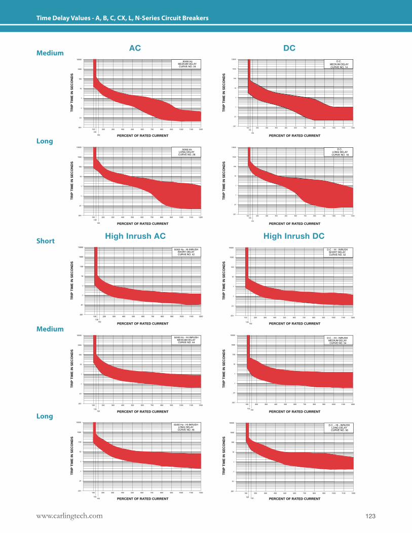
123www.carlingtech.com
Time Delay Values - A, B, C, CX, L, N-Series Circuit Breakers
Medium
Short
Long
Medium
Long
AC
High Inrush AC High Inrush DC
DC
TR
IP T
IME
IN S
EC
ON
DS
PERCENT OF RATED CURRENT
TR
IP T
IME
IN S
EC
ON
DS
PERCENT OF RATED CURRENT
TR
IP T
IME
IN S
EC
ON
DS
PERCENT OF RATED CURRENTT
RIP
TIM
E IN
SE
CO
ND
S
PERCENT OF RATED CURRENT
TR
IP T
IME
IN S
EC
ON
DS
PERCENT OF RATED CURRENT
TR
IP T
IME
IN S
EC
ON
DS
PERCENT OF RATED CURRENT
TR
IP T
IME
IN S
EC
ON
DS
PERCENT OF RATED CURRENT
TR
IP T
IME
IN S
EC
ON
DS
PERCENT OF RATED CURRENT
TR
IP T
IME
IN S
EC
ON
DS
PERCENT OF RATED CURRENT
TR
IP T
IME
IN S
EC
ON
DS
PERCENT OF RATED CURRENT
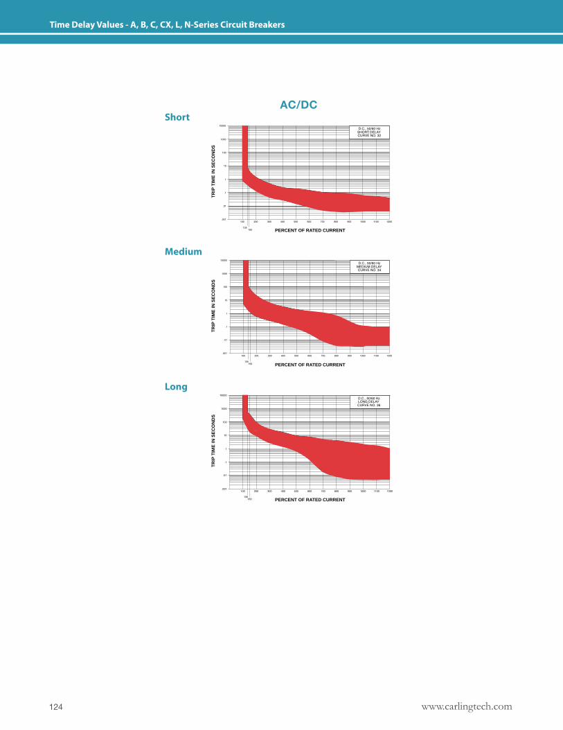
www.carlingtech.com124
Time Delay Values - A, B, C, CX, L, N-Series Circuit Breakers
Short
Long
Medium
AC/DC
TR
IP T
IME
IN S
EC
ON
DS
PERCENT OF RATED CURRENT
TR
IP T
IME
IN S
EC
ON
DS
PERCENT OF RATED CURRENT
TR
IP T
IME
IN S
EC
ON
DS
PERCENT OF RATED CURRENT
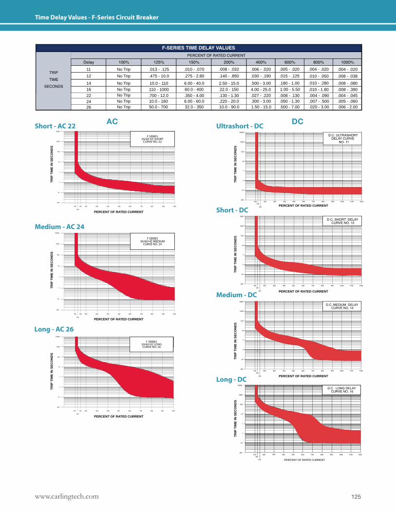
125www.carlingtech.com
Time Delay Values - F-Series Circuit Breaker
22
16
14
12
11
No TripNo Trip
No Trip
No Trip
No Trip
.700 - 12.0
110 - 1000
10.0 - 110
.475 - 10.0
.013 - .125
10.0 - 16050.0 - 700
.350 - 4.00
60.0 - 400
6.00 - 40.0
.275 - 2.80
.010 - .070
6.00 - 60.032.0 - 350
.130 - 1.30
22.0 - 150
2.50 - 15.0
.140 - .850
.008 - .032
.220 - 20.010.0 - 90.0
.027 - .2204.00 - 25.0
.500 - 3.00
.030 - .190
.006 - .020
.300 - 3.001.50 - 15.0
.008 - .130
1.00 - 5.50
.180 - 1.00
.015 - .125
.005 - .020
.050 - 1.30
.500 - 7.00
.004 - .090.010 - 1.80
.010 - .280
.010 - .050
.004 - .020
.007 - .500
.020 - 3.00
.004 - .045
.004 - .020
.008 - .390
.008 - .080
.008 - .038
.005 - .060
.006 - 2.00No TripNo Trip
2426
Long - AC 26
Short - AC 22 Ultrashort - DC
Short - DC
Medium - DC
Medium - AC 24
DCAC
TR
IP T
IME
IN S
EC
ON
DS
F SERIES50/60 HZ SHORT
CURVE NO. 22
TR
IP T
IME
IN S
EC
ON
DS
PERCENT OF RATED CURRENT
TR
IP T
IME
IN S
EC
ON
DS
PERCENT OF RATED CURRENT
TR
IP T
IME
IN S
EC
ON
DS
PERCENT OF RATED CURRENT
Long - DC
TR
IP T
IME
IN S
EC
ON
DS
PERCENT OF RATED CURRENT
F SERIES50/60 HZ MEDIUM
CURVE NO. 24
TR
IP T
IME
IN S
EC
ON
DS
PERCENT OF RATED CURRENT
F SERIES50/60 HZ LONGCURVE NO. 26
TR
IP T
IME
IN S
EC
ON
DS
PERCENT OF RATED CURRENT
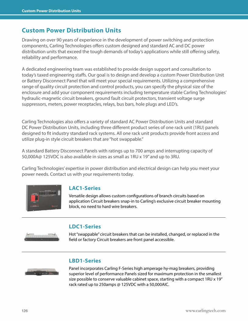
www.carlingtech.com126
Custom Power Distribution Units
Drawing on over 90 years of experience in the development of power switching and protection components, Carling Technologies offers custom designed and standard AC and DC power distribution units that exceed the tough demands of today’s applications while still offering safety, reliability and performance.
A dedicated engineering team was established to provide design support and consultation to today’s taxed engineering staffs. Our goal is to design and develop a custom Power Distribution Unit or Battery Disconnect Panel that will meet your special requirements. Utilizing a comprehensive range of quality circuit protection and control products, you can specify the physical size of the enclosure and add your component requirements including temperature stable Carling Technologies’ hydraulic-magnetic circuit breakers, ground fault circuit protectors, transient voltage surge suppressors, meters, power receptacles, relays, bus bars, hole plugs and LED’s.
Carling Technologies also offers a variety of standard AC Power Distribution Units and standard DC Power Distribution Units, including three different product series of one rack unit (1RU) panels designed to fit industry standard rack systems. All one rack unit products provide front access and utilize plug-in style circuit breakers that are “hot swappable.”
A standard Battery Disconnect Panels with ratings up to 700 amps and interrupting capacity of 50,000A@ 125VDC is also available in sizes as small as 1RU x 19” and up to 3RU.
Carling Technologies’ expertise in power distribution and electrical design can help you meet your power needs. Contact us with your requirements today.
Versatile design allows custom configurations of branch circuits based on application Circuit breakers snap-in to Carling’s exclusive circuit breaker mounting block, no need to hard wire breakers.
Hot “swappable” circuit breakers that can be installed, changed, or replaced in the field or factory Circuit breakers are front panel accessible.
Panel incorporates Carling F-Series high amperage hy-mag breakers, providing superior level of performance Panels sized for maximum protection in the smallest size possible to conserve valuable cabinet space, starting with a compact 1RU x 19” rack rated up to 250amps @ 125VDC with a 50,000AIC.
Custom Power Distribution Units
LAC1-Series
LDC1-Series
LBD1-Series
127www.carlingtech.com
Carling Technologies Materials
Below is a list of useful product catalogs. Please scan the QR codes below or visit carlingtech.com/onthego for complete details.
Rocker, Toggle, Pushbutton & RotarySWITCHES & CONTROLS
CATALOG
/onthego catalog
catalog
catalog
catalog
catalog
carlingtech.com
Switches and ControlsRocker, toggle, pushbutton, rotary, battery disconnects and controls.
WEBSITEProduct Selector, Resources, Configurit, Find Rep, Product Materials and Videos.
Hydraulic-Magnetic circuit protection1-6 poles from .02 to 700A with CSA, VDE, TUV, UL489, UL489A, UL1500 approvals.
GFCI/ELCI circuit protection1-3 poles from 0.10 to 50A with CSA, UL489, UL1077, UL1053, UL1500 approvals.
Mini & Sub-Mini SwitchesSealed and non-sealed rocker, toggle, pushbutton and slide options.
Thermal circuit protection1 pole from 3 to 60A with UL, cUL, CE, UL1500/ISO 8846 approvals.
Rocker, Toggle, Pushbutton & SlideMINIATURE SWITCHES
CATALOG
Circuit Protection
CATALOG
Circuit ProtectionTHERMAL
CATALOG
Circuit ProtectionGFCI / ELCI
CATALOG
www.carlingtech.com128
Carling Technologies Materials
Below is a list of useful market specific catalogs and brochures. Please scan the QR codes below or visit carlingtech.com/onthego for complete details.
brochure
brochure
brochure
brochure
brochure
brochurecatalog
catalog
catalog
catalog
catalog
Telecom/DatacomHydraulic-Magnetic Circuit Breakers
RENEWABLE ENERGYCircuit Breakers and Disconnect products
On-Off HighwaySwitches, Controls and Custom Solutions
MilitaryCOTS Switches and Circuits Breakers
MarineCircuit Protection and Switches
Industrial AutomationSwitches and Circuit Breakers
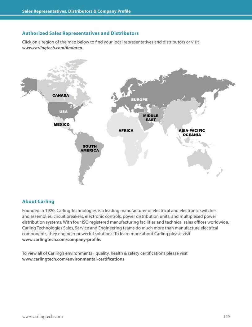
129www.carlingtech.com
Sales Representatives, Distributors & Company Profile
Authorized Sales Representatives and Distributors
About Carling
Founded in 1920, Carling Technologies is a leading manufacturer of electrical and electronic switches and assemblies, circuit breakers, electronic controls, power distribution units, and multiplexed power distribution systems. With four ISO registered manufacturing facilities and technical sales offices worldwide, Carling Technologies Sales, Service and Engineering teams do much more than manufacture electrical components, they engineer powerful solutions! To learn more about Carling please visit www.carlingtech.com/company-profile.
To view all of Carling’s environmental, quality, health & safety certifications please visit www.carlingtech.com/environmental-certifications
Click on a region of the map below to find your local representatives and distributors or visit www.carlingtech.com/findarep.
EUROPE
MIDDLEEAST
SOUTHAMERICA
ASIA-PACIFICOCEANIA
AFRICAMEXICO
USA
CANADA
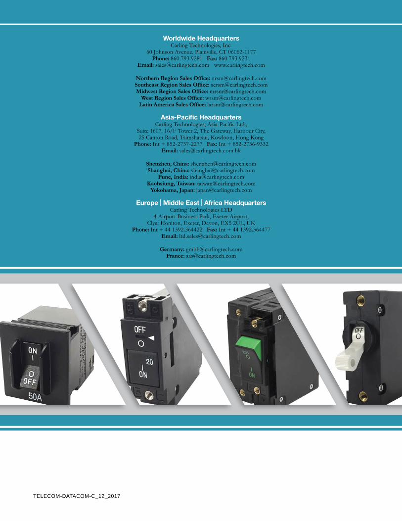
TELECOM-DATACOM-C_12_2017
Worldwide HeadquartersCarling Technologies, Inc.
60 Johnson Avenue, Plainville, CT 06062-1177Phone: 860.793.9281 Fax: 860.793.9231
Email: [email protected] www.carlingtech.com
Northern Region Sales Office: [email protected] Region Sales Office: [email protected] Region Sales Office: [email protected]
West Region Sales Office: [email protected] America Sales Office: [email protected]
Asia-Pacific HeadquartersCarling Technologies, Asia-Pacific Ltd.,
Suite 1607, 16/F Tower 2, The Gateway, Harbour City, 25 Canton Road, Tsimshatsui, Kowloon, Hong Kong
Phone: Int + 852-2737-2277 Fax: Int + 852-2736-9332Email: [email protected]
Shenzhen, China: [email protected], China: [email protected]
Pune, India: [email protected], Taiwan: [email protected]
Yokohama, Japan: [email protected]
Europe | Middle East | Africa HeadquartersCarling Technologies LTD
4 Airport Business Park, Exeter Airport, Clyst Honiton, Exeter, Devon, EX5 2UL, UK
Phone: Int + 44 1392.364422 Fax: Int + 44 1392.364477Email: [email protected]
Germany: [email protected]: [email protected]