
Telecom Requirements for Time and Frequency Synchronization
36
Telecom Requirements for Time and Frequency Synchronization Marc Weiss, Ph.D. Time and Frequency Division, NIST And Speakers from WSTS
Transcript of Telecom Requirements for Time and Frequency Synchronization

Telecom Requirements for Time
and Frequency Synchronizationand Frequency Synchronization
Marc Weiss, Ph.D.
Time and Frequency Division, NIST
And Speakers from WSTS
Outline
• Evolution of Sync
– SONET/SDH
– Packet-based networks
• Mobile Standards and Sync• Mobile Standards and Sync
• LTE-Advanced
• E911
• Conclusions

Excerpts from WSTS
• The NIST-ATIS-Telcordia Workshop on Synchronization in Telecom Systems– Occurs annually since 1992
– Much of the content here is directly reproduced from WSTS talks given by experts in their field
• WSTS and its European sister ITSF represent a global alliance of pre-eminent experts in synchronization for telecom and related applications. Many of these experts act as steering group members for both conferences, as well as sit on various standards bodies including ITU, ATIS and IETF.
Evolution of Telecom Sync
• Formerly, the network was “synchronous” (really syntonous!)– Data transport required same frequency distributed through
different quality of clocks call strata
– The same bandwidth was used for data transport between nodes, independent of trafficnodes, independent of traffic
• The network has evolved to have an asynchronous, or packet, core, with access technologies such as wireless cell networks at the edge– Packet data does not require syntonization, and uses scalable
bandwidth
– Syntonization and now true synchronization is now required for services and apps at the edge of the network and for users

Telecom Receivers are Generally
Stationary, Used for Time and
Frequency Only
Example of NIST receiver is similar

SONET/SDH Systems
• Synchronous Optical NETwork developed and deployed in the US and Canada in the 80’s and 90’s
• Synchronous Digital Hierarchy generalizes SONET in that it is the form in ITU-T and used throughout in that it is the form in ITU-T and used throughout the world besides N. America
• SONET/SDH are transport systems still in use that require frequency synchronization
– Data and voice can be carried over SONET/SDH
– Packet data can be carried over SONET/SDH
Packet-Based Networks
• The physical layer can be Ethernet, or other system that does not require sync– This allows variable bandwidth and more scalable
systems
– However services still require various kinds of sync and the network requires special transport systems to
– However services still require various kinds of sync and the network requires special transport systems to deliver that
• Many network elements obtain sync from GPS and other GNSS– These signals are vulnerable to interference
– ITU-T and other standards bodies have on-going work to standardize sync transport over packet

Timing Technology: Frequency
Accuracy• Frequency accuracy (FFO) is the
difference in frequency between
the server clock and the recovered
client clock over a time interval
• Frequency targets
– ± 32 ppm for Stratum 4 & 4E
– ± 4.6 ppm for Stratum 3 & 3E
– ± 50 ppb for GSM & WCDMA-FDD
Frequency (ppm)
Master
Clock
Slave Clock
Frequency
Accuracy
– ± 50 ppb for GSM & WCDMA-FDD
– ± 100 ppb for Home NodeB
Time (s)
© 2011 Microsemi Corporation.
Thanks to Adam Wertheimer, Microsemi Co. for the use of this slide.

Timing Technology: Phase
• Alignment and PPS
• Phase alignment is in addition to phase lock. Phase alignment also referred to as Latency Correction.
• Phase alignment has– Bounded phase offset between server
clock and recovered client clock
– Bounded phase offset between different recovered client clocks
Master Clock
Slave Clock 1
0 1 2
recovered client clocks
• Phase alignment requires bi-directional mechanism
• Phase alignment targets
– ± 1.25 µs for WCDMA-TDD
– ± 3 µs for CDMA2000, CDMAone
– ± 1 µs for WiMAX
Slave Clock 1
Slave Clock 2
5 6 7
1 2 3
© 2011 Microsemi Corporation.
Thanks to Adam Wertheimer, Microsemi Co. for the use of this slide.

SONET/SDH Frequency Sync
Strata 4 and 4E support 32 ppm
Free-Run Holdover
Clock Designation Long Term
Accuracy
(±±±± PPM)
Holdover Stability
(±±±± PPM)
STS Pointer Generation STS Pointer Generation
Stratum 1 .00001 N/A 1 every 4.3 hours N/A
Stratum 2 .016 .0001 1 every 9.6 sec 1 every 25.72 min
Stratum 3E 4.6 0.012 29.81 /sec 1 every 12.86 sec
Stratum 3 4.6 0.37 29.81/sec 2.39 /secStratum 3 4.6 0.37 29.81/sec 2.39 /sec
SMC 20 4.6 129.60 /sec 29.81 /sec
Stratum 4E 32 N/A 207.36 /sec N/A
Stratum 4 32 N/A 207.36 /sec N/A
Note:
1. STS pointer generation relative to 0 ppm.
2. 1 STS pointer is equivalent to a one-way phase movement of 154 ns.
3. Pointer generation reflects the maximum frequency offset per clock type.
4. Long-term accuracy is also known as free-run accuracy.
5. SONET payload integrity guaranteed to +/- 4.6 ppm (bold red)

GPS/GNSS meets Stratum 1 Requirements
with a Good Local Oscillator
• Stratum 1 requires 10-11 frequency accuracy
– 10 ns at 15 minutes, 100 ns at 3 hours
– This is 0.01 ppb– This is 0.01 ppb
• Maybe beyond a Qu, achievable with a CSAC or Rb Oscillator
• Holdover is an important consideration
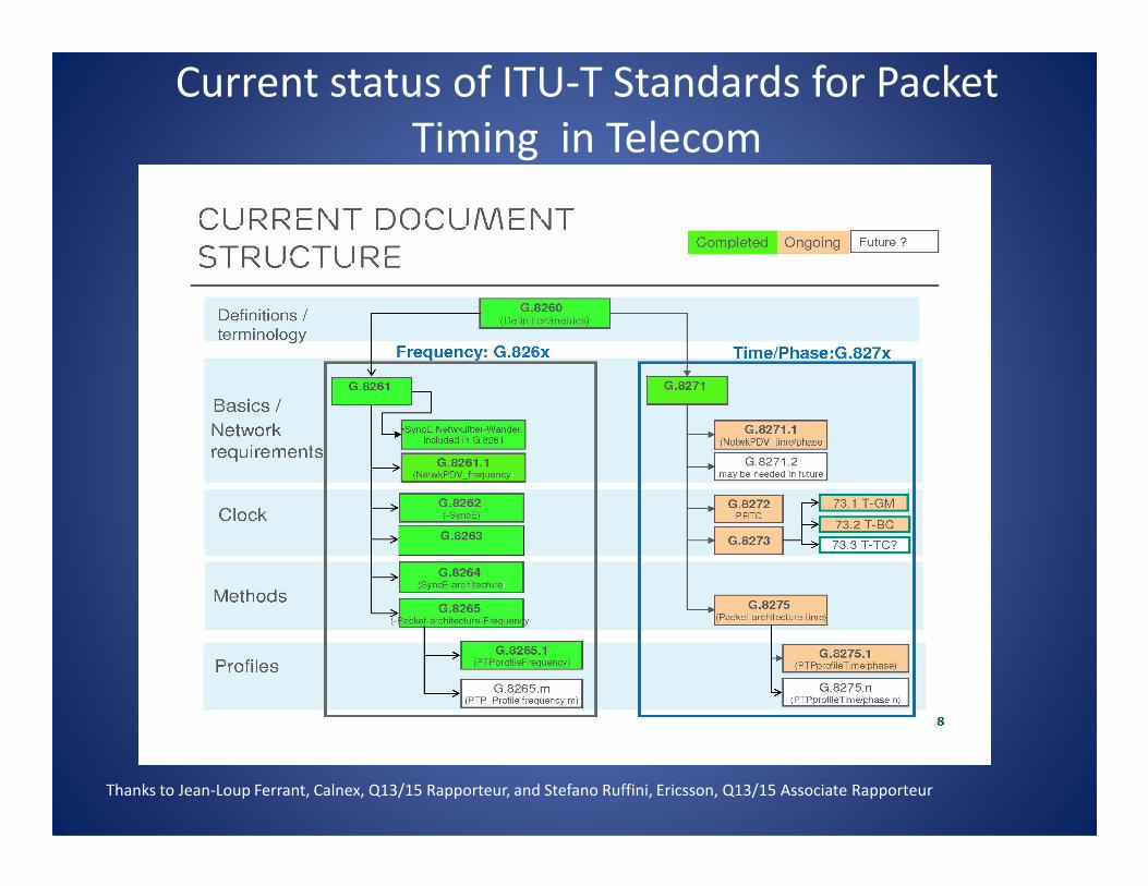
Current status of ITU-T Standards for Packet
Timing in Telecom
Thanks to Jean-Loup Ferrant, Calnex, Q13/15 Rapporteur, and Stefano Ruffini, Ericsson, Q13/15 Associate Rapporteur
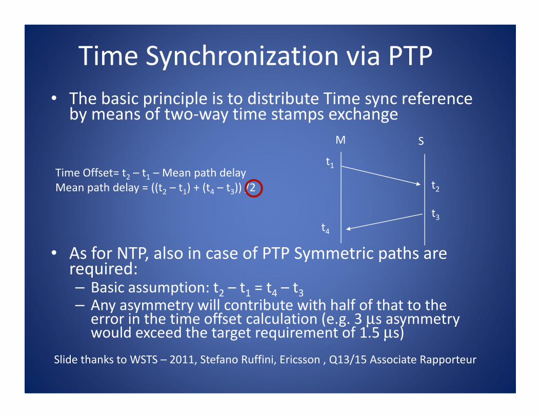
Time Synchronization via PTP
• The basic principle is to distribute Time sync reference by means of two-way time stamps exchange
t1
t2
t
M S
Time Offset= t2 – t1 – Mean path delay
Mean path delay = ((t2 – t1) + (t4 – t3)) /2
• As for NTP, also in case of PTP Symmetric paths are required:– Basic assumption: t2 – t1 = t4 – t3
– Any asymmetry will contribute with half of that to the error in the time offset calculation (e.g. 3 µs asymmetry would exceed the target requirement of 1.5 µs)
t4
t3
Slide thanks to WSTS – 2011, Stefano Ruffini, Ericsson , Q13/15 Associate Rapporteur

Is “full IEEE 1588 support” good
enough ?• Removal of PDV and asymmetry in the nodes by means of
IEEE1588 support (e.g. Boundary Clock in every node).
PTP
Master
PRTC
T-BC T-BC T-BC SOOCEnd
App. . .
PRTC : Primary Reference Time Clock
T-BC: Telecom - Boundary Clock
SOOC: Slave Only Ordinary Clock
› Ideally the full support can provide very accurate timing,
however several sources of errors still remains
Slide thanks to WSTS – 2011, Stefano Ruffini, Ericsson , Q13/15 Associate Rapporteur

Current Frequency Sync Requirements
from ATIS TR on Intra-Office NetworksFrequency Applications and use cases (based on G.8261 appendix IV)
• Existing network where a free-run accuracy of +/-32 ppm is needed for end-equipment. Slips may become a problem. These slips may interfere with voice-band modem communications.
• If the system also supports SONET, then an accuracy of better than +/- 4.6 ppm is needed.
• If the system also supports SONET, then an accuracy of better than +/- 4.6 ppm is needed.
• Wireless technologies. – +/-50 ppb for GSM (and other related technology) base stations
– +/-16ppb In some cases, this requirement is tightened
– Based on 3GPP TS25.105 and TS36.101, frequency requirements that may apply in addition to the phase requirements :
• ±50 ppb for wide-area base stations
• 100 ppb for local-area base stations
• 250 ppb for home base stations
Thanks to Adam Wertheimer, Microsemi Co. for this information.

Current and Evolving Time Sync Requirements
from ATIS TR on Intra-Office Networks
• Phase Applications and use cases (based on G.8271 appendix II)– 1 ms to 500 ms for billing and alarm collection systems. It is
common to use NTP for this application.
– For IP delay monitoring, an accuracy of up to 5 microseconds is needed.needed.
– LTE-TDD and CDMA-based wireless systems need an accuracy of 1.5 – 5 microseconds.
– UTRA-TDD and LTE-TDD (small cell) need an accuracy of 1 – 1.5 microseconds.
– In some configurations, WiMAX-TDD and LTE-A have additional requirements below 1 microsecond.
– A feature in LTE-A may require time sync below 1 microsecond (discussed later)
Thanks to Adam Wertheimer, Microsemi Co. for this information.
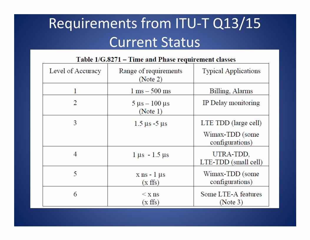
Requirements from ITU-T Q13/15
Current Status
Meeting Sync Requirements in Telecom
• UTC accuracy and stability brought into network generally with GNSS and local oscillator– Short term stability depends on local oscillator
– Hold-over also depends on local oscillator
– E.g. holding 1 microsecond for a day cannot be done with a Quoscillatoroscillator
• GNSS requires an antenna and sky view. Vulnerability is an issue
• Time and frequency sync is often spread from the receiver through the network– Network elements add noise and errors in various forms
– Passing 1 microsecond time sync is hard, limited by distance

Excerpts from:
Mobile standards & synchronization:
3GPP, etc.
WSTS - 2012
Stefano Ruffini, Ericsson

CDMA Track (3GPP2)
GSM Track (3GPP)
LTE
FDD and TDD
GSM WCDMA HSPA
TD-SCDMA
Evolution of mobile technologies
CDMA Track (3GPP2)
2001 2005 2008 2010
FDD and TDD
CDMA One EVDO Rev A
Mobile applications and
Synchronization• The needs of Transport and switching networks have
been the main drivers for sync standardization in the 90s– Mobile applications only as side users (e.g. Synchronous
PDH signals are used to synchronize the GSM network in frequency)
• The needs of Mobile networks are now the main • The needs of Mobile networks are now the main drivers of the sync standardization activities in ITU-T: – Several bodies where synchronization is a key topic (3GPP,
MEF, BBF, NGMN)
• Discussions between ITU-T and 3GPP on the sync aspects not always easy:– Use of different terminologies– Different focus
3GPP: 3rd Generation Partnership
Project • 3GPP was created in December 1998. Currently 6 Partners.
• “The purpose of 3GPP is to prepare, approve and maintain globally applicable
Technical Specifications and Technical Reports for:
– an evolved 3rd Generation and beyond Mobile System based on the evolved
3GPP core networks, and the radio access technologies supported by the Partners
(i.e., UTRA both FDD and TDD modes), to be transposed by the Organizational
Partners into appropriate deliverables (e.g., standards).Partners into appropriate deliverables (e.g., standards).
– the Global System for Mobile communication (GSM) including GSM evolved radio
access technologies (e.g. General Packet Radio Service (GPRS) and Enhanced Data
rates for GSM Evolution (EDGE)).
– an evolved IMS developed in an access independent manner.”
(From “3GPP Scope and Objectives Approved by 3GPP Organizational Partners
by correspondence 31 August 2007”)

CDMA 2000 Synchronization
Requirements
• Time Synchronization Requirements
±
3GPP2 C.S0010-B: Recommended Minimum Performance Standards
for cdma2000 Spread Spectrum Base Stations
3GPP2 C.S0002-C: Physical layer standard for cdma2000
Spread Spectrum Systems
– ± 3 µs with respect to CDMA System Time (which is traceable and synchronous to UTC)
– ± 10 µs with respect to CDMA System Time for a period not less than 8 hours (when the external source of CDMA system time is disconnected)
GPS Receiver is typically deployed at every Base Station

Additional sync requirements for TDD
mode
…
256 s
2ms
5ms
10 ms
5µs
1ms
Phase Synchronization (Radio Interface) requirements are defined in TS 25.402
These apply to UTRA-TDD systems (e.g. TD-CDMA, TD-SCDMA)
256 s10 ms
The relative phase difference of the synchronization
Signal shall not exceed 2.5 µs (3 µs is mentioned for TD-SCDMA)
Node B
External sync Source (e.g. GPS)
Sync in Sync out
Node B
Sync inSync out
Sync inNode B
The Requirements is +/-1.25 µs for independent inputs to the NodeBs
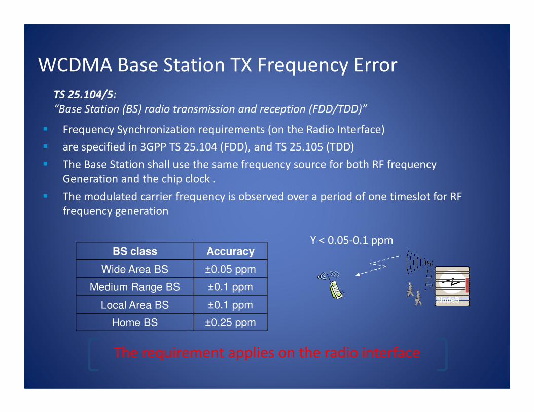
WCDMA Base Station TX Frequency Error
� Frequency Synchronization requirements (on the Radio Interface)
� are specified in 3GPP TS 25.104 (FDD), and TS 25.105 (TDD)
� The Base Station shall use the same frequency source for both RF frequency
Generation and the chip clock .
� The modulated carrier frequency is observed over a period of one timeslot for RF
frequency generation
TS 25.104/5:
“Base Station (BS) radio transmission and reception (FDD/TDD)”
Y < 0.05-0.1 ppm
frequency generation
NodeB
BS class Accuracy
Wide Area BS ±0.05 ppm
Medium Range BS ±0.1 ppm
Local Area BS ±0.1 ppm
Home BS ±0.25 ppm
The requirement applies on the radio interface

LTE Base Station TX Frequency Error
• Frequency Synchronization (Radio Interface) requirements:
– The same source shall be used for RF frequency and data clock generation.
– The modulated carrier frequency of the BS observed over a period of one subframe (1ms)
shall be accurate to within
TS 36.104: “Evolved Universal Terrestrial Radio Access
(E-UTRA); Base Station (BS) radio transmission and reception
BS class AccuracyY < 0.05-0.25 ppm
Requirements at the input of the eNodeB depends on the actual implementation
(for instance network limits are defined in case the frequency reference is distributed over
the physical layer, TDM or Synchronous Ethernet)
BS class Accuracy
Wide Area BS ±0.05 ppm
Local Area BS ±0.1 ppm
Home BS ±0.25 ppm
eNodeB
The requirement applies on the radio interface

LTE-TDD Phase Synchronization
RequirementsTS 36.133: “Evolved Universal Terrestrial Radio Access
(E-UTRA); Requirements for support of radio resource management
TS 36.922: “Evolved Universal Terrestrial Radio Access (E-UTRA);
TDD Home eNode B (HeNB) Radio Frequency (RF) requirements analysis”
Maximum absolute deviation in frame start timing between any pair of cells on the same frequency that have overlapping coverage areas
LTE-TDD - 3usec for small cell (< 3km radius), LTE-TDD(Wide-Area Base
station
- 3usec for small cell (< 3km radius),
- 10usec for large cell ( > 3km radius)
LTE-TDD(Home-Area Base
station)
- 3 usec for small cell (< 500m radius).
- 1.33 + Tpropagation µµµµs, for large cell (> 500m radius),
Tpropagation: propagation delay between the Home BS and the cell
selected as the network listening synchronization source
LTE-TDD to CDMA handovers(Synchronized E-UTRAN)
- eNodeB shall be synchronized to GPS time.
- With external source of CDMA system time disconnected, the eNodeB shall maintain the timing accuracy within ± 10usec of CDMA
system time for a period of not less than 8 hours
Excerpts from:
Deutsche Telekom
Time/Phase Synchronization Requirements
for LTE-Advanced Wireless Systems including
CoMP
Deutsche Telekom at WSTS 2011Helmut Imlau, Heinz Droste
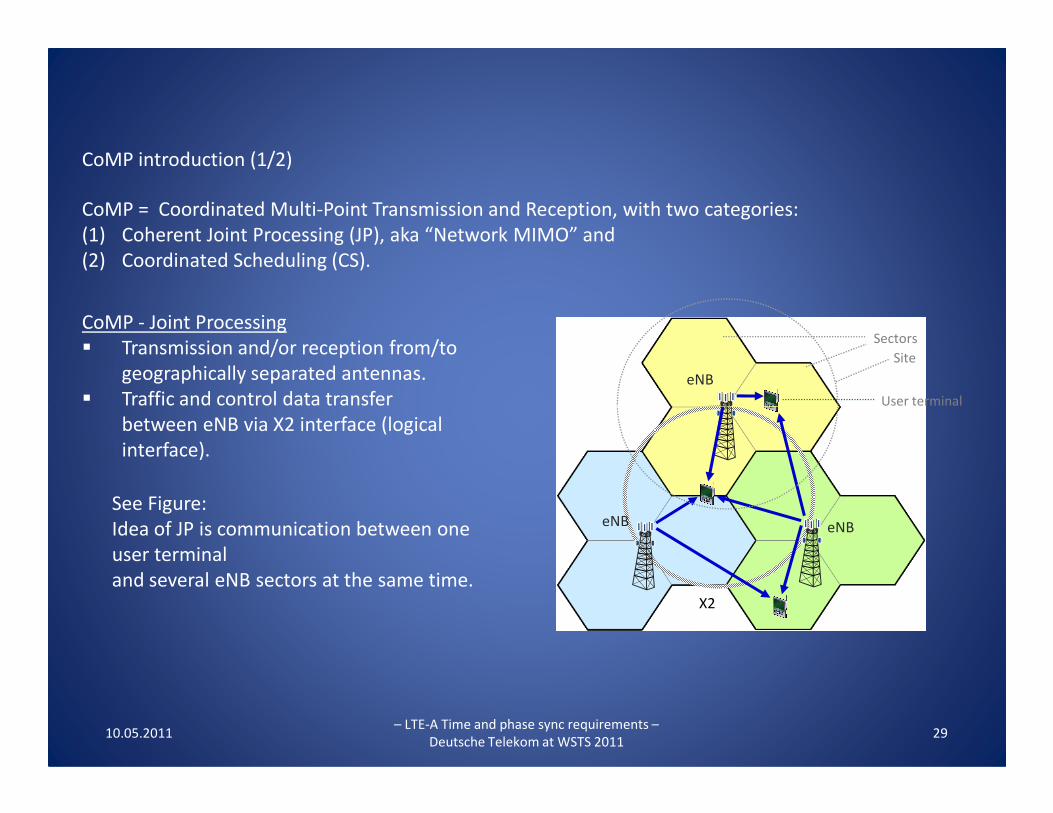
CoMP = Coordinated Multi-Point Transmission and Reception, with two categories:
(1) Coherent Joint Processing (JP), aka “Network MIMO” and
(2) Coordinated Scheduling (CS).
CoMP - Joint Processing
� Transmission and/or reception from/to
geographically separated antennas.
� Traffic and control data transfer eNB
CoMP introduction (1/2)
Sectors
Site
User terminal
10.05.2011– LTE-A Time and phase sync requirements –
Deutsche Telekom at WSTS 201129
� Traffic and control data transfer
between eNB via X2 interface (logical
interface).
X2
eNB eNB
See Figure:
Idea of JP is communication between one
user terminal
and several eNB sectors at the same time.
User terminal

CoMP = Coordinated Multi-Point Transmission and Reception, with two categories:
(1) Coherent Joint Processing (JP), aka “Network MIMO” and
(2) Coordinated Scheduling (CS)
CoMP - Coordinated Scheduling (CS)
� Dynamic allocation of air interface resources
in overlapping cells.
� Control data exchange between eNB (incl.
Pico-eNB) via X2 interface
CoMP introduction (2/2)
Sectors
Site
eNB
10.05.2011– LTE-A Time and phase sync requirements –
Deutsche Telekom at WSTS 201130
Pico-eNB) via X2 interface
(X2 for control data only).
� The decision must be made right in time,
which eNB / which resource is going to serve which
user terminal, depending on user terminal location,
bandwidth requirement and speed.
X2Pico-eNB
eNB eNB
� Coordinated Scheduling options:
=> decentralized per cooperation cluster or
=> centralized (per super cell => fixed number of cells that cooperate
including several cooperation clusters). Every user is served by its "Serving Cell" only.

This talk explains the challenging time/phase synchronization requirements
for CoMP Joint Processing (CoMP-JP) as an example for LTE-Advanced.
Accuracy calculation for time and phase is made
with a very few input parameters only: Sectors
Site
eNB
CoMP-JP time/phase synchronization requirements (1/8)
� Already specified signal structure for
10.05.2011
– LTE-A Time and phase sync requirements
– Deutsche Telekom at WSTS
2011
31
X2
eNB eNB
� Already specified signal structure for
LTE/LTE-A
� Typical multi-path propagation signal
decay time
� Inter-Site-Distance (ISD) and
� Speed of light.
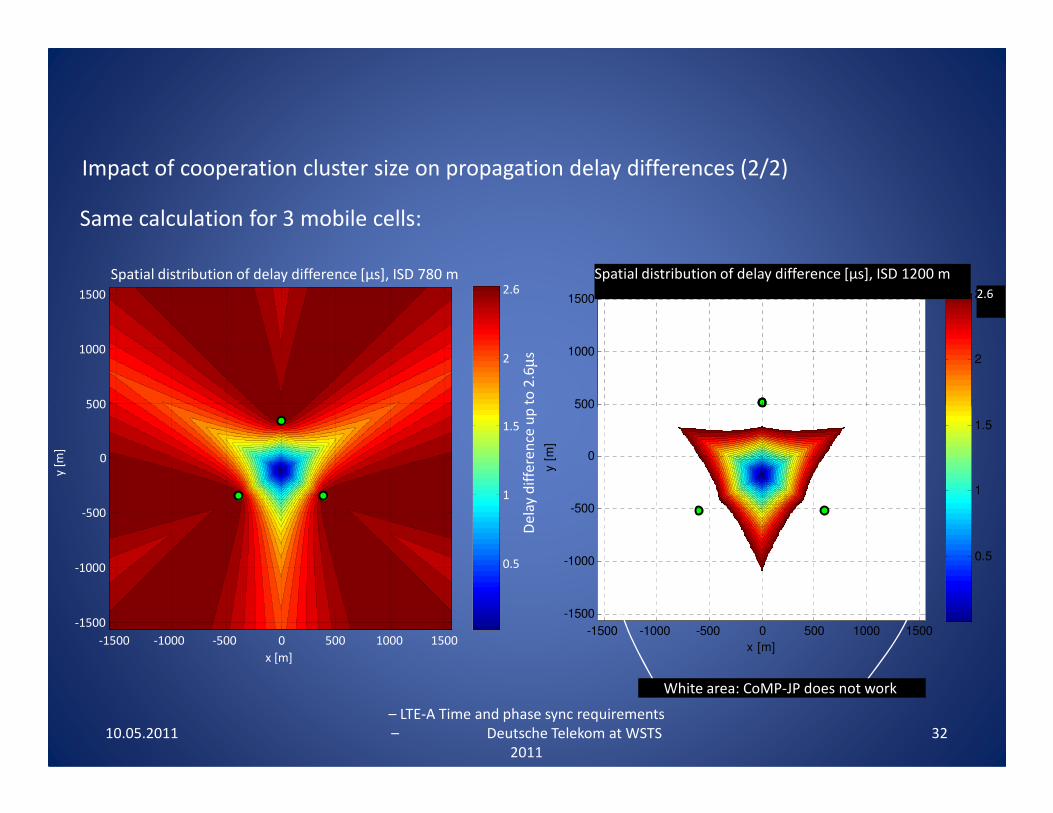
Same calculation for 3 mobile cells:
Impact of cooperation cluster size on propagation delay differences (2/2)
Spatial distribution of delay difference [µs], ISD 780 m
500
1000
1500
2
2.6Spatial distribution of delay difference [µs], ISD 1200 m
500
1000
1500
2
2.5
Spatial distribution of delay difference [µs], ISD 1200 m
2.6
De
lay d
iffe
ren
ce u
p t
o 2
.6µ
s
10.05.2011
– LTE-A Time and phase sync requirements
– Deutsche Telekom at WSTS
2011
32
x [m]
y [
m]
-1500 -1000 -500 0 500 1000 1500
-1500
-1000
-500
0
500
0.5
1
1.5
x [m]
y [
m]
-1500 -1000 -500 0 500 1000 1500
-1500
-1000
-500
0
500
0.5
1
1.5
White area: CoMP-JP does not work
De
lay d
iffe
ren
ce u
p t
o 2
.6

To operate CoMP Joint Processing the following time budget calculation can
be used:
4.6 µs = Length of the Cyclic Prefix = maximum budget
- 1.0 µs = Budget for multi path propagation decay time
- 1.0 µs = Budget for time error ± 500 ns
Summary
Budget
4.0µs
4,6µs4.6µs
3.6µs
10.05.2011
– LTE-A Time and phase sync requirements
– Deutsche Telekom at WSTS
2011
33
- 1.0 µs = Budget for time error ± 500 ns
=2.6 µs
2.6 µs is related to maximum Inter-Site Distance of 780 m.
1.0µs
2.0µs
3.0µs
780m 2.6µs
180m 0.6µs
For comparison: With a time error of ± 1.5 µs (TDD requirement)
the maximum ISD for CoMP JP would be 180 m.

Enhanced 9-1-1 Wireless Services
• FCC requirements have a Phase I and Phase II
• Under Phase II, the FCC requires wireless carriers, within six months of a valid request by a Public Safety Answering Point (PSAP), to begin providing the latitude and longitude of the caller.
• Accuracy standards are generally to within 50 to 300 • Accuracy standards are generally to within 50 to 300 meters, depending on the type of technology used.
• 50 m = 150 ns for positioning. With a PDOP of 1.5 (as an example), this means 100 ns per range
• For a caller within a building or where GPS is unavailable, the base stations require this appropriate level of time synchronization

Sync from GNSS at ~100 ns
• At a few ~100 ns, calibration of receivers becomes very important– Absolute calibration must typically last for the lifetime of
the equipment
• Impedance matching in antenna cables is also required– Poor matching can cause 10’s of ns variation in the code – Poor matching can cause 10’s of ns variation in the code
lock point over time
• These requirements might be relaxed if systems can accomplish common-view time transfer– Systems really need differential calibration
– This effectively performs a differential calibration in real time

Summary and Conclusions
• GPS and GNSS meets frequency sync requirements for SONET/SDH with a good oscillator– Stratum 1 requires 10-11 frequency accuracy
– 10 ns at 15 minutes, 100 ns at 3 hours– 10 ns at 15 minutes, 100 ns at 3 hours
• Wireless telecom is driving new sync requirements– Frequency sync requirements up to 50 ppb
– Time sync requirements up to 0.5 microsecond or perhaps more
• E911 may require sync at the 100 ns level


