Telecom Engineering WDM Lite Manual r7 · 2009-08-12 · Telecom Engineering DWDM/CWDM/WDM Lite™...
8
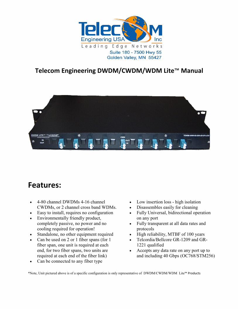
Telecom Engineering DWDM/CWDM/WDM Lite™ Manual Features: *Note, Unit pictured above is of a specific configuration is only representative of DWDM/CWDM/WDM Lite™ Products • 4-80 channel DWDMs 4-16 channel CWDMs, or 2 channel cross band WDMs. • Easy to install, requires no configuration • Environmentally friendly product, completely passive, no power and no cooling required for operation! • Standalone, no other equipment required • Can be used on 2 or 1 fiber spans (for 1 fiber span, one unit is required at each end, for two fiber spans, two units are required at each end of the fiber link) • Can be connected to any fiber type • Low insertion loss - high isolation • Disassembles easily for cleaning • Fully Universal, bidirectional operation on any port • Fully transparent at all data rates and protocols • High reliability, MTBF of 100 years • Telcordia/Bellcore GR-1209 and GR- 1221 qualified • Accepts any data rate on any port up to and including 40 Gbps (OC768/STM256)
Transcript of Telecom Engineering WDM Lite Manual r7 · 2009-08-12 · Telecom Engineering DWDM/CWDM/WDM Lite™...
Telecom Engineering DWDM/CWDM/WDM Lite™ Manual
Features:
*Note, Unit pictured above is of a specific configuration is only representative of DWDM/CWDM/WDM Lite™ Products
• 4-80 channel DWDMs 4-16 channel
CWDMs, or 2 channel cross band WDMs.
• Easy to install, requires no configuration
• Environmentally friendly product,
completely passive, no power and no
cooling required for operation!
• Standalone, no other equipment required
• Can be used on 2 or 1 fiber spans (for 1
fiber span, one unit is required at each
end, for two fiber spans, two units are
required at each end of the fiber link)
• Can be connected to any fiber type
• Low insertion loss - high isolation
• Disassembles easily for cleaning
• Fully Universal, bidirectional operation
on any port
• Fully transparent at all data rates and
protocols
• High reliability, MTBF of 100 years
• Telcordia/Bellcore GR-1209 and GR-
1221 qualified
• Accepts any data rate on any port up to
and including 40 Gbps (OC768/STM256)
Revision 1.5 1
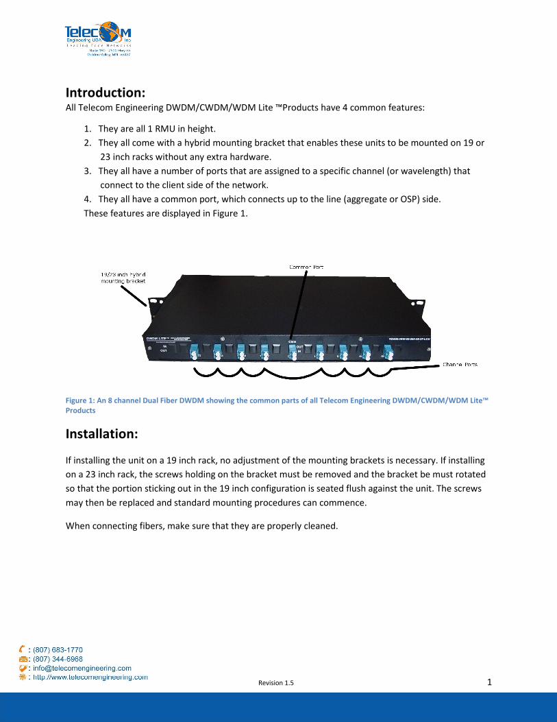
Introduction: All Telecom Engineering DWDM/CWDM/WDM Lite ™Products have 4 common features:
1. They are all 1 RMU in height.
2. They all come with a hybrid mounting bracket that enables these units to be mounted on 19 or
23 inch racks without any extra hardware.
3. They all have a number of ports that are assigned to a specific channel (or wavelength) that
connect to the client side of the network.
4. They all have a common port, which connects up to the line (aggregate or OSP) side.
These features are displayed in Figure 1.
Figure 1: An 8 channel Dual Fiber DWDM showing the common parts of all Telecom Engineering DWDM/CWDM/WDM Lite™
Products
Installation:
If installing the unit on a 19 inch rack, no adjustment of the mounting brackets is necessary. If installing
on a 23 inch rack, the screws holding on the bracket must be removed and the bracket be must rotated
so that the portion sticking out in the 19 inch configuration is seated flush against the unit. The screws
may then be replaced and standard mounting procedures can commence.
When connecting fibers, make sure that they are properly cleaned.
Revision 1.5 2
Setting up a DWDM/CWDM/WDM system:
There are 3 basic setups that are commonly used in DWDM/CWDM/WDM systems. They are dual units
over two fibers; single units over two fibers; and single units over one fiber. Each covered in more detail
below. Channel compatibility with transmit sources should also be checked, as all Telecom Engineering
DWDM/CWDM/WDM Lite™ Products use the standardized ITU-T channel grid listed in Appendix A.
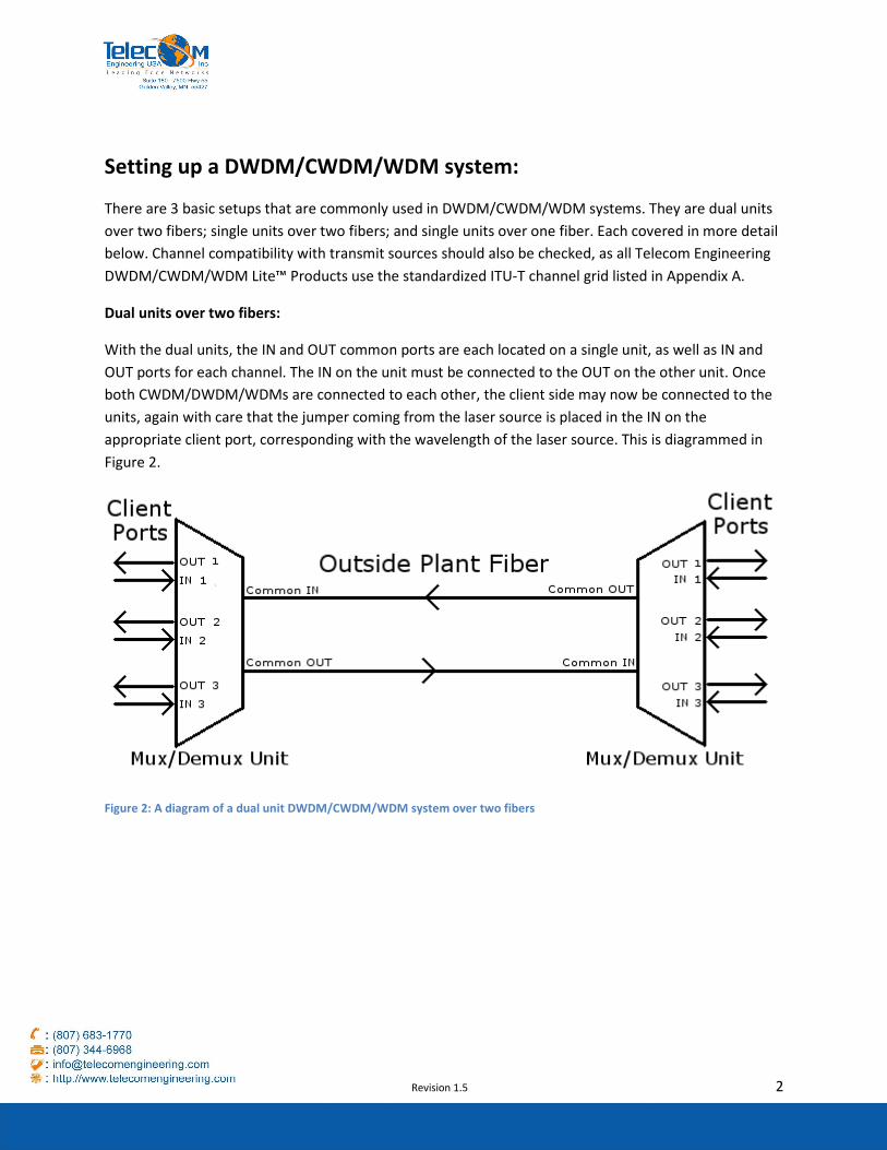
Dual units over two fibers:
With the dual units, the IN and OUT common ports are each located on a single unit, as well as IN and
OUT ports for each channel. The IN on the unit must be connected to the OUT on the other unit. Once
both CWDM/DWDM/WDMs are connected to each other, the client side may now be connected to the
units, again with care that the jumper coming from the laser source is placed in the IN on the
appropriate client port, corresponding with the wavelength of the laser source. This is diagrammed in
Figure 2.
Figure 2: A diagram of a dual unit DWDM/CWDM/WDM system over two fibers
Revision 1.5 3
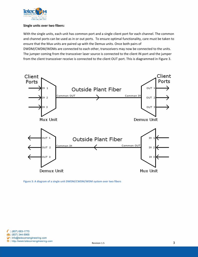
Single units over two fibers:
With the single units, each unit has common port and a single client port for each channel. The common
and channel ports can be used as in or out ports. To ensure optimal functionality, care must be taken to
ensure that the Mux units are paired up with the Demux units. Once both pairs of
DWDM/CWDM/WDMs are connected to each other, transceivers may now be connected to the units.
The jumper coming from the transceiver laser source is connected to the client IN port and the jumper
from the client transceiver receive is connected to the client OUT port. This is diagrammed in Figure 3.
Figure 3: A diagram of a single unit DWDM/CWDM/WDM system over two fibers
Revision 1.5 4
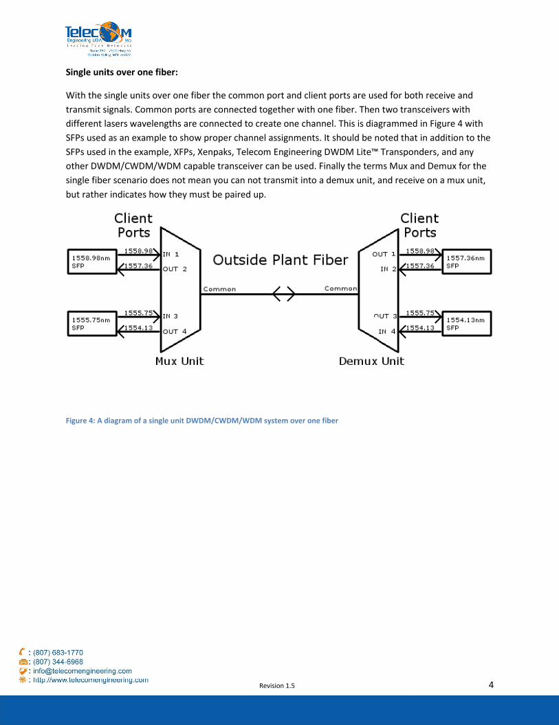
Single units over one fiber:
With the single units over one fiber the common port and client ports are used for both receive and
transmit signals. Common ports are connected together with one fiber. Then two transceivers with
different lasers wavelengths are connected to create one channel. This is diagrammed in Figure 4 with
SFPs used as an example to show proper channel assignments. It should be noted that in addition to the
SFPs used in the example, XFPs, Xenpaks, Telecom Engineering DWDM Lite™ Transponders, and any
other DWDM/CWDM/WDM capable transceiver can be used. Finally the terms Mux and Demux for the
single fiber scenario does not mean you can not transmit into a demux unit, and receive on a mux unit,
but rather indicates how they must be paired up.
Figure 4: A diagram of a single unit DWDM/CWDM/WDM system over one fiber
Revision 1.5 5
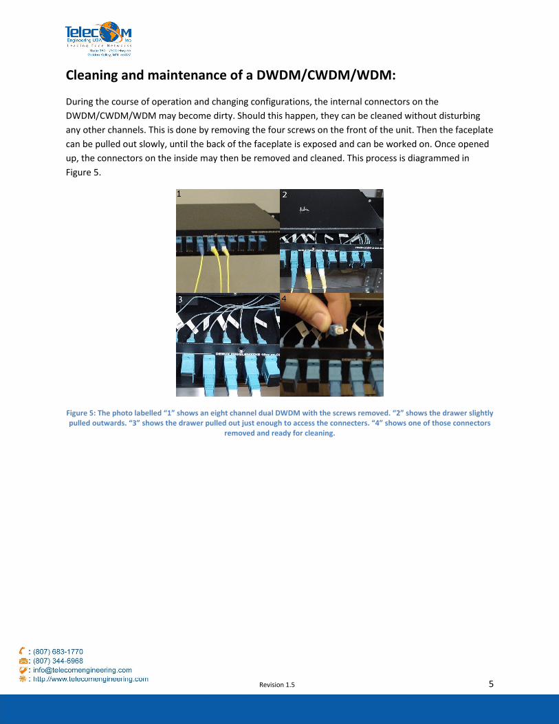
Cleaning and maintenance of a DWDM/CWDM/WDM:
During the course of operation and changing configurations, the internal connectors on the
DWDM/CWDM/WDM may become dirty. Should this happen, they can be cleaned without disturbing
any other channels. This is done by removing the four screws on the front of the unit. Then the faceplate
can be pulled out slowly, until the back of the faceplate is exposed and can be worked on. Once opened
up, the connectors on the inside may then be removed and cleaned. This process is diagrammed in
Figure 5.
Figure 5: The photo labelled “1” shows an eight channel dual DWDM with the screws removed. “2” shows the drawer slightly
pulled outwards. “3” shows the drawer pulled out just enough to access the connecters. “4” shows one of those connectors
removed and ready for cleaning.
Revision 1.5 6
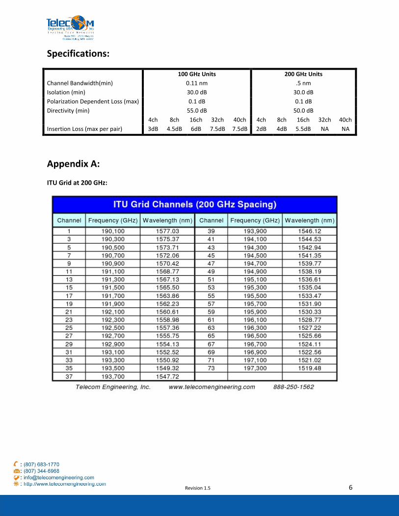
Specifications:
100 GHz Units 200 GHz Units
Channel Bandwidth(min) 0.11 nm .5 nm
Isolation (min) 30.0 dB 30.0 dB
Polarization Dependent Loss (max) 0.1 dB 0.1 dB
Directivity (min) 55.0 dB 50.0 dB
4ch 8ch 16ch 32ch 40ch 4ch 8ch 16ch 32ch 40ch
Insertion Loss (max per pair) 3dB 4.5dB 6dB 7.5dB 7.5dB 2dB 4dB 5.5dB NA NA
Appendix A:
ITU Grid at 200 GHz:
Revision 1.5 7
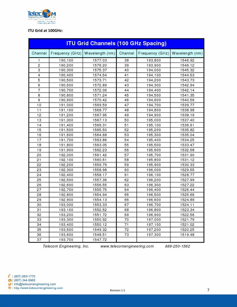
ITU Grid at 100GHz: