Dccn-Cellular Telephone And Satellite Networks and Global System for Mobile Communication

TELE4652 Mobile and Satellite Communication Systems
Lecture 11 – 3G Cellular Systems Almost as soon as the second generation cellular networks were deployed engineers began planning for the next generation of cellular networks. 2G systems were designed as mobile telephone systems, designed and optimised to communicate voice over a network following the traditional circuit-switched ideas of landline telephony. In the evolution of these second generation cellular network, paralleled with the rapid growth of the internet, made it clear that 3G networks would need to be designed to effectively and efficiently communicate a much wider and diverse range of data types than simply voice. The move towards the efficient provision of a wide variety of data types, such as voice, text messages, internet pages, emails, pictures, up to multimedia streaming, had three important consequences for the design of third generation systems.
(i) The evolution towards a packet switched (and mostly a TCP/IP) backbone, since packet switched systems are more efficient in handling a diverse range of data.
(ii) The ability to flexibly and efficiently alter the air-interface data rate. The data rate demanded for a live video feed is many times greater than that needed for a phone conversation.
(iii) The ability to provide a varying degree of data robustness. The effect of errors in the transmission of telephone quality speech is perceptually very different from an equivalent number of errors in the download of a webpage, for instance.

The International Telecommunications Union (ITU) initially set out to achieve a world-wide universal standard for the 3G cellular systems, to allow seamless global roaming anywhere in the world, and hence overcame the incompatibilities the different 2G technologies (an IS-95 mobile handset could never work on a GSM network, for instance). This was drafted as the International Telecommunications (IMT-2000) initiative. The IMT-2000 was conceived as high-speed wireless communications to support multimedia, data, and video, in addition to voice. The plan, drafted in 1995, envisaged the integration of cellular, cordless, paging, and low earth orbit satellite systems into a single network capable of providing comparable performance as fixed-line systems. Some aspects of the IMT-2000 plan were:
- Complete global coverage using terrestrial and satellite systems. - Common worldwide spectral allocation. - 144 kbps available to high-speed users over a wide area. - 384 kbps available to low-speed users over a small area. - Up to 2.048 Mbps in stationary, office environments. - The provision of asymmetrical data rates, to reflect the asymmetry
between outbound and inbound traffic naturally experienced on the internet.
- Support for both packet switched and circuit switched services. - More efficient use of the available radio spectrum. - Ease of interface with a wide variety of mobile equipment. - Flexibility in the adoption of new technologies and services.
However, due to the inherited legacy of the second generation systems two dominant and incompatible 3G networks have emerged. The W-CDMA system, which evolved from the GSM system; and the cdma2000 network, that was a natural evolution from IS-95. Both these major systems are share broad similarities, with their main differences stemming from the different networks they evolved from. In this lecture we will briefly describe both these standards. CDMA was the multiple access technique of choice for 3G networks, after the high performance of the IS-95 CDMA networks had made its advantages clear. We have discussed these advantages in detail in earlier lectures. In particular they are the high system capacity through universal frequency re-use and the soft capacity limit; the use of the RAKE receiver and the robustness to multipath fading; soft handoffs and macrodiversity; and the inherent security and handset power efficiency. Moreover, CDMA is better suited for packet-based networks, where bandwidth can be easily allocated on demand. The universal bandwidth adopted for 3G networks is 5 MHz. This was a trade-off on the need to increase the bandwidth to achieve greater data rates and robustness to multipath fading, and the availability of spectrum for competing needs. The bandwidth allocation allows chip rates in excess of 3 Mcps, though the precise value depends on the level of error control adopted and the modulation scheme employed. A central feature of 3G networks is the ability to provide logical channels with different data rates to end users, depending on application.

We’ll now discuss the details of the W-CDMA network standard and then briefly discuss the cdma2000, with primary interest to highlight the differences between the two standards. The body governing the formation of the W-CDMA standard became known as the Third Generation Partnership Project (3GPP), while the body governing the cdma2000 family of standards is called the 3GPP2.
W-CDMA W-CDMA was the eventual name for the 3G standard produced by the 3GPP, created in 1998 out of the work of the European Telecommunication Standards Institute (ETSI). The physical layer design is often referred to as UMTS Terrestrial Radio Access Network (UTRAN). W-CDMA represents the evolution of the GSM network into 3G. The evolutionary path followed was that of HSCSD, GPRS, and EDGE. These incremental upgrade steps were largely to allow network operators to progressively grow demand for 3G services and develop applications. The transition into 3G was always going to be difficult and costly for operators, since it involved a fundamental switch across the air interface from TDMA to a CDMA-based radio link. From the point of view of the engineers formulating the standards, though, not being burdened by the IS-95 legacy allowed a fresh and considerably superior air-interface to be drafted. The channel allocation was 5 MHz for both the uplink and the downlink. Two frequency bands were initially identified for use as W-CDMA: the first was 1920-1980 MHz uplink, 2110-2170 MHz downlink; the second was for 1850-1910 MHz uplink, 1930-1990 MHz downlink. Channels were allocated as FDD pairs spaced by 190 MHz for the first allocation, and 80 MHz for the second allocation. There is a second standard for W-CDMA, denoted TD-WCDMA, since it in most aspects similar to W-CDMA but uses Time Division Duplexing (TDD). It is far less widely spread in deployment in existing cellular networks.
Network Functionality The W-CDMA network supports both circuit-switched and packet-switched data, and as such the network contains elements of both types. A sketch of the W-CDMA network is shown in the diagram below. The network still has the traditional GSM circuit-switched elements, such as the BTS, BSC, and MSC, with their usual functionality. It also adds the GPRS elements, SGSN and GGSN, to perform the packet data routing tasks. The primary addition, documented as UTRAN, is a Radio Network Subsystem (RNS), to provide the 3G functionality over the air-interface. It consists of the Radio Network Controller (RNC), with functionality equivalent to the old GSM-based BSC, while the physical antenna link onto the air-interface is called ‘Node B’. The RNS provides the packet-based CDMA functionality of this 3G network. The user equipment in the 3G network is naturally considerably more flexible. The core element is once again the SIM card, though in W-CDMA this is called the Universal SIM (USIM), to indicate the intention to provide global roaming capability.

The format of the USIM, and in particular its components like the UIMSI, are sufficiently similar to their GSM counterparts to not justify documenting them here.
Note the need for W-CDMA to maintain the traditional circuit-switched backbone, since packet-based networks cannot necessarily maintain the severe delay requirements needed for real-time streaming voice data. The design methodology in W-CDMA is to still have voice traffic passed over the circuit-switched network, with other data traffic routed over the packet-switched network. Advancements in Voice over IP (VoIP) telephony, thanks largely to increases in network-level data rates, has made the communication of voice data over a packet-switched network feasible. It is proposed that 4G networks will be wholly packet-switched. W-CDMA naturally employs RAKE receivers to provide diversity gain. The higher bandwidth and chip rate employed improves the RAKE receiver performance and allows a greater number of multipath components to be resolved. The chip rate of 3.84Mcps corresponds to a chip period of 0.26µs, allowing multipath components with path differences of only 78 metres to be resolved. This is a considerable improvement on that achieved in IS-95 CDMA, where multipath diversity was only achieved on a macro-cellular level. In all CDMA networks power control is imperative. W-CDMA specifies both rapid open loop power control with a slower closed loop power control loop. Power control instructions are inserted into each frame, called a Transmission Time Interval (TTI) in W-CDMA speak. TTIs are 10ms in duration, so closed loop power control happens at a rate of 100 Hz. A particular feature of W-CDMA is that each active mobile or User Equipment (UE) transmits its own pilot, which is multiplexed into its transmitted

signal. This pilot tone not only allows coherent detection for the uplink, but can also be used by the base station for power level and interference level measurements.
In most other aspects the functionality of the network is similar to GSM and its packet-switched enhancement, GPRS. In general the packet-switched methodology means less connections and signalling overheads. Given time and space we will not have the opportunity to explore these ideas here.
Protocol Stack The protocol stack used in W-CDMA conforms to the OSI model, and is in essence the combination of the GSM protocol, with provisions for a CDMA physical layer, with the GPRS packet-switched protocol layers.

A broad overview of the W-CDMA protocol stack is illustrated below. The upper layers are called the Non-Access Stratum, and are primarily concerned with network level signalling. On the circuit-switched side, the Connection Management layer handles functions such as call establishment, call release, short message services, and supplementary services such as call forwarding. The mobility management governs circuit-switched domain mobility functions such as location area update. These circuit-switched layers are essentially the same as those found in GSM. The packet-switched side of things was taken from GPRS. The session management layer deals with packet-switched call establishment and call release. The GPRS mobility management manages packet-switched domain mobility functions such as routing area update.
The Access stratum is considerably different from those in GSM and GPRS, due to the switch to the CDMA physical layer. The Radio Resource Control (RRC) Layer handles the broadcast of system information, connection management, radio bearer management, paging and notification functions, control of ciphering and integrity protection, power control, and measurement control and reporting. The Radio Link Control (RLC) Layer performs segmentation, reassembly, concatenation, padding, retransmission control, flow control, duplicate detection, error correction and ciphering. The Medium Access Control (MAC) Layer handles the mapping and multiplexing of logical channels to transport channels, priority handling, traffic volume measurements, and random access channel procedures. The physical layer handles CRC attachment and error detection, coding and decoding, interleaving, multiplexing, rate matching, power weighting, modulation, spreading, scrambling, closed loop power control, frequency and time synchronisation. A more detailed diagram of the protocol layers is shown in the diagram below. In particular it highlights the new layers added to supplement the basic GSM/GPRS protocol stack. As mentioned in previous lectures, detailed discussion of the implementation of the various protocol layers in cellular networks is well beyond the scope of this course.

Channel Structure The channel structure used in W-CDMA is a little more complex than that found in 2G networks. There are now three types of channels: logical channels; transport channels; and physical channels. The logical channels define the type of data to be transferred, and are fundamentally associated with how the MAC layer interfaces to the layers above it. The transport channels define how and with what type of characteristic logical channels are to be transferred. As before, the physical channel corresponds to the spreading and scrambling codes used and the frequency carrier used. The diagram below shows a rough diagram of the various channel mappings.

The main types of logical channels are: BCCH (Broadcast Control Channel) – Downlink only. Broadcasts system and cell specific information. PCCH (Paging Control Channel) – Downlink only. For paging and short messages. DCCH (Dedicated Control Channel) – Bi-directional. For point to point control information transfer. CCCH (Common Control Channel) – Bi-directional. For point to multipoint control information transfer. DTCH (Dedicated Traffic Channel) – Bi-directional. To transmit user data. CTCH (Common Traffic Channel) – Downlink point to multipoint channel. For the transfer of data to multiple users. Transport channels then consist of a group of logical channels to achieve a means to an end. These channels are all uni-directional. RACH (Random Access Channel) – Uplink, contention-based channel, using the Slotted ALOHA protocol. Used for initial access or non-real-time dedicated control or user data. Has a limited size data field. CPCH (Common Packet Channel) – Uplink, contention-based channel, for the transmission of bursty data traffic. FACH (Forward Access Channel) – Downlink common channel, and may carry small amounts of user data. DSCH (Downlink Shared Channel) – Used for dedicated control or traffic data. Associated to a DCH (doesn’t exist alone). BCH (Broadcast Channel) – Downlink, for the broadcast of system and cell specific data. PCH (Paging Channel) – Downlink. DCH (Dedicated Channel) – Either uplink or downlink, and associated with a single UE. The physical channels can be classified as follows. Note that not all physical channels are obtained from logical channels – some carry out functions specific to the physical layer. These are largely indication channels, to facilitate the successful operation of the physical layer. As such, their information is of no interest to the higher protocol layers. CPICH (Common Pilot Channel) – this is at a fixed data rate of 30 kbps. There are two types: Primary CPICH, used as a phase reference for the SCH, primary CCPCH, AICH, and PICH, and other downlink physical channels; and the Secondary CPICH, used as a reference for the secondary CCPCH and the downlink DCH.

CCPCH (Primary – Common Control Physical Channel) – carries the BCH at 30 kbps. CCPCH (Secondary – Common Control Physical Channel) – carries the FACH and PCH, and is variable rate. SCH (Synchronisation Channel) – used for cell searches. PDSCH (Physical Downlink Shared Channel) – carries the DSCH, and always associated to a DPDCH. AICH (Acquisition Indicator Channel) – carries signatures for the random access procedure. PICH (Page Indication Channel) – carries indicators to indicate the presence of paging messages on the PCH. AP-AICH (Access Preamble Acquisition Indicator Channel) – carries AP acquisition indicators of the associated CPCH. CSICH (CPCH Status Indicator Channel) – carries CPCH status information. CD/CA-ICH (Collision Detection/Channel Assignment Indicator Channel). DPDCH (Dedicated Physical Data Channel) – carries a DCH, containing data from above layer 2. DPCCH (Dedicated Physical Control Channel) – carries uplink control information. PRACH (Physical Random Access Channel) – carries the RACH. PCPCH (Physical Common Packet Channel) – carries the CPCH. These physical channels are then assigned a channelisation code and scrambling code as will be described later. In the uplink, a user can simultaneously transmit up to six DPDCH channels and one DPCCH, as shown below, as dependent on the desired data rate.

The channelisation codes are the orthogonal spreading codes, and the scrambling codes are the PN or Gold code sequences. The DPCCH is always sent on the Q-phase. The different channel gains can be adjusted to meet different QoS requirements for the different channels. Downlink physical channels are processed as shown below. All downlink channels, with the exception of the SCH (Synchronisation Channel), are processed in the same way as uplink channels.
An example of the structure of an uplink Dedicated Channel TTI is shown in the diagram below. Note the use of Quadrature Multiplexing to associate a DPCCH to a DPDCH. The information contained in the DPCCH includes the pilot tone, to allow the base station to perform coherent detection on the user’s data signal. The TFCI field, the Transport Format Combination Indicator, indicates the data transmission rate used in the associated DPDCH. The TPC field is the Transmission Power control, used for the closed loop power control. The optional Feedback Information (FBI) is planned for use in future standards, such as those involving smart antennae. The uplink timeslot structure is a little different, however. The control and data channels are Time Division Multiplexed (TDM). Note also that each 10 ms frame is sub-divided into a 15 timeslots, each of duration 2/3 ms.

Physical Layer Due to the need to provide different data rates, variable length spreading codes are used. Spreading factors range from 4 to 512, in power of two, for the downlink, and 4 to 256 in the uplink. Orthogonal Variable Length Spreading Factor (OVSF) Codes are used, which are formed from a tree of different length Walsh codes as shown in the diagram below. Every codeword of any length is orthogonal to any other codeword as long as they sit on distinct tree branches, that is, they do not have a branch in common. In W-CDMA user data is transmitted in 10ms blocks containing 2560 chips. The precise raw data rate is ultimately determined by the channel conditions, and depends on the FEC rate, error detection and tail bits, and the control overheads. Control data is multiplexed with transmission as was described. Data rates in the reverse direction are one half that in the forward direction, due to BPSK modulation being used in the reverse and QPSK in the forward. Like in IS-95, W-CDMA employs a variety of spreading codes: channelisation codes, the OVSF, to distinguish users; and scrambling codes to provide further security and minimise inter-cell interference.
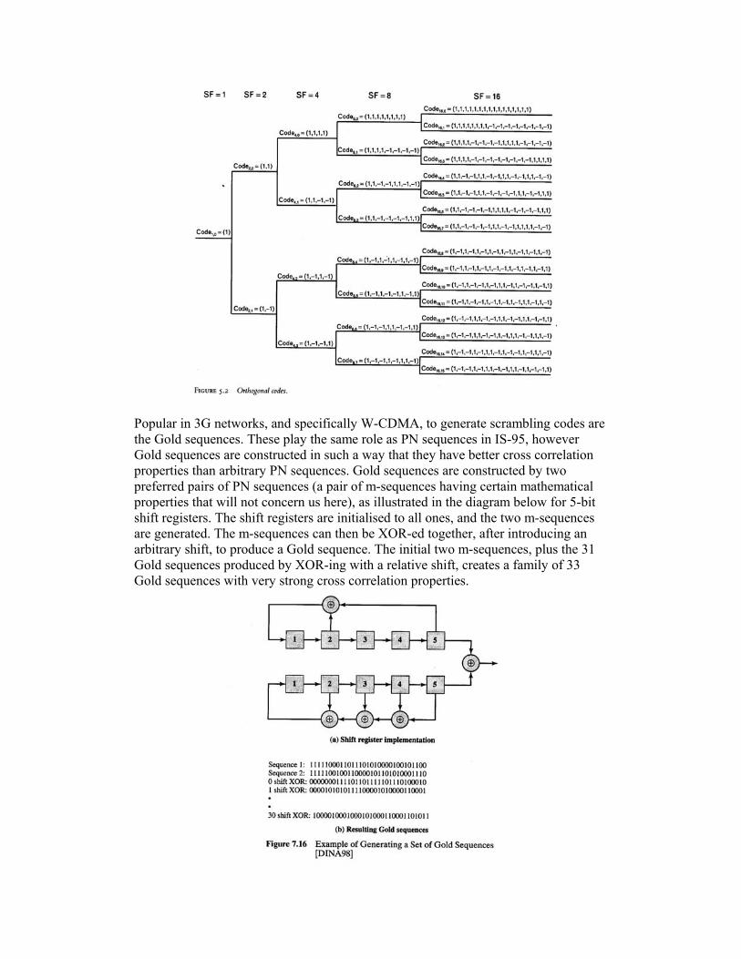
Popular in 3G networks, and specifically W-CDMA, to generate scrambling codes are the Gold sequences. These play the same role as PN sequences in IS-95, however Gold sequences are constructed in such a way that they have better cross correlation properties than arbitrary PN sequences. Gold sequences are constructed by two preferred pairs of PN sequences (a pair of m-sequences having certain mathematical properties that will not concern us here), as illustrated in the diagram below for 5-bit shift registers. The shift registers are initialised to all ones, and the two m-sequences are generated. The m-sequences can then be XOR-ed together, after introducing an arbitrary shift, to produce a Gold sequence. The initial two m-sequences, plus the 31 Gold sequences produced by XOR-ing with a relative shift, creates a family of 33 Gold sequences with very strong cross correlation properties.

Forward Error Correction is primarily performed using convolutional codes. The convolutional encoders specified in the standard are shown below. Convolutional encoders are specified for use at low data rates, while the idea was that Turbo codes would come in at the higher data rates.
Turbo codes are particularly well suited to packet-based networks, where transmitted packets can be longer than the typical 20 ms frame common for speech. Turbo codes achieve much higher efficiency than convolutional codes when the message length is relatively long. The rate 1/3 turbo coder specified in the standard is shown below. The general difficulty in implementing turbo codes is the high level of computational overheads required in the decoding process.

As already described, the data process before modulation involves the application of the channelisation code and then the scrambling code. The Downlink uses QPSK modulation. The scrambling codes generally ensure fairly good power profile performance.
The diagram below shows the signal processing used on transport channels on the downlink. Most of the essential features have already been discussed.

The uplink procedure is fairly similar, as shown below. The primary difference is that BPSK modulation is used for the uplink (note, though, that the spreading signals are complex, or phase sensitive).
W-CDMA adopted a very efficient variable rate voice codec, called Algebraic Code Excited Linear Predictive Coder (ACELP).
High Speed Packet Access (HSPA) In the never ceasing quest for greater data rates, two further enhancements to were made to W-CDMA to evolve it from its TDMA-based origin to take advantage of the ability of packet-switched principles to improve efficiency over the air-interface. These two additions, called HSDPA and HSUPA, can coexist with the core W-

CDMA system, and essentially overlay a high speed and high efficiency data transfer protocol over the basic W-CDMA scheme. The first was High-Speed Downlink Packet Access (HSDPA), finalised in 2006 and already being deployed worldwide. HSDPA has the potential to provide users with data rates of the order of 9 Mbps, in ideal conditions. They features of the revised standard, known as UMTS Release 5, were:
- 16 QAM modulation. - A highly-efficient rate 1/3 turbo coder. - Rapid feedback on channel conditions. - Time-division multiplexing of user transmission using maximum
channel resources. - Dynamic maximisation and adjustment of transmit power. - Use of multiple code channels. - Use of code division multiplexing (CDM) for multi-user
transmission during a TDM interval. - Incremental redundancy in the form of Hybrid ARQ (H-ARQ).
HSDPA seeks to maximise the data rate based on rapid estimates of the channel conditions and the available power. The radio link of the HSDPA thus features many users sharing the channel in a TDM fashion, with resources varying on a packet-by-packet and user-to-user basis, depending on channel conditions. In HSDPA each TDM interval or frame is 2ms in duration, and can be assigned to one or more users. The spreading factor for each user is fixed at 16, and each of the 15 available spreading codes (one is reserved for radio link control) can be dynamically assigned to users. One or more users can receive forward link transmission in a single frame. Available system is dynamically assigned to improve performance, meaning the HSDPA system essentially controls and optimises all radio communication resources dynamically based on channel conditions and traffic load. The control information, on the designated spreading code, is transmitted 1.3 ms ahead of the given frame. There are no soft-handoffs in HSDPA. The operation of the HSDPA downlink is as follows:
1. Every 2 ms each mobile unit that has an active packet data connection measures and reports its channel quality in the form of a Channel Quality Indicator (CQI) value.
2. A scheduler at Node B considers a variety of factors (CQIs of servicing mobiles, length of data queues, subscriber profiles, and fairness measures), and determines which users will be serviced in the next frame.
3. Based on the reported CQIs, and the data buffer lengths, the base station determines the data rate and the modulation type for each selected user.
4. Upon receipt of the transmitted information, and after verification with the CRC code, the each user responds with an ACK or NACK.
Note that turbo coders are particularly well suited to H-ARQ. The data packet is transmitted over three frames. The first frame contains the systematic output, and the next two the parity check outputs. The user will first receive the original data, and if this is found to be not in error, an ACK is sent and the base station does not need to bother to send the subsequent frames. If errors are found, the MS can wait for the
parity check bits to progressively arrive, and sequentially decoding performance will improve. The H-ARQ can thus increase net throughput, by only transmitting extraneous data if it is truly required. In 2007 HSDPA was followed by UMTS Release 6, known as High Speed Uplink Packet Access (HSUPA). As with HSDPA, it achieves increased peak data rates and average user throughput, reduced latency, and higher spectral efficiency, through the application of packet principles to the uplink. The large gain in performance comes then in large part from efficient and intelligent algorithms to dynamically allocate channel resources, as in HSDPA. HSUPA has some differences to HSDPA. The reverse link in CDMA is interference limited, since it is difficult to obtain non-synchronised orthogonal scrambling codes. HSUPA take the interference level on the network into account in its allocation of resources, vie monitoring the power levels received for each mobile units pilot signal. HSUPA uses macrodiversity and soft handoffs, by way of the familiar ‘active set’. Power control commands are sent at a rate of 1500 Hz.
Cdma2000 The first 3G network that was commercially employed was the cdma2000 1x EV-DO network. It was an extension to the IS-95 standard, and as such is sometimes referred to as IS-95b. The ‘1x’ refers to it using the same chip rate (1.2288 Mcps) as IS-95, EV-DO means ‘evolutionary- data only’. It full-filled a similar role in the evolution of IS-95 as GPRS did for GSM – essentially it over-laid a packet-switched core onto the IS-95 network. Cdma2000 1x EV-DO was conceived as a data only network, but with Voice-over-IP (VoIP) technology it can support voice data too. The idea was that this system could co-exist as a separate data-only 1.25 MHz channel allocated to an operator also using other 1.25 MHz channels for standard IS-95 CDMA networks. Typical data rates for cdma2000 1x EV-DO range from 300 kbps to 1.2 Mbps depending on the time of day, with instantaneous data rates of 2.4 Mbps possible. In particular, the data rates on the forward channel vary from 38.4 kbps to 2.4576 Mbps, while on the uplink they range from 9.6 kbps to 156.3 kbps. Designing the network with a purely packet-switched infrastructure increasing the performance in two major ways: Firstly, interconnection to external, largely packet-based networks is considerably easier; and secondly, packet-routing tends to result in increased performance, particularly in terms of bandwidth efficiency, over the air-interface. Voice communications is extremely intolerant to transmission delays, and as such speech frames are short, typically 20 ms in duration. Short frames introduce considerable overheads and thus reduced efficiency. Packet-based networks can increase packet length to the order of 100 ms or more, improving efficiency. A feature of cdma2000 1x EV-DO was the adaptive modulation and coding strategy. This plays a similar role to power control in the traditional CDMA based network. In the forward link the base station always transmits at the maximum power. Those MS close the base station receive a high SNR, and so have channels with a high capacity.

For the MS far away from the base station, the low SNR will introduce significant errors into the received signals. The data rate is reduced on these low capacity channels through the use of stronger error control coding (reducing the data rate, by the increase in code rate), and reducing to a lower order modulation scheme (16QAM, 8PSK, and QPSK are permitted for the forward link, while only BPSK is used on the reverse link). This is adaptive rate control, where the adjustment of FEC coding rate, modulation, and the number of repetitions allow the link to be adapted to channel conditions, while the power level and the chip rate remain fixed. The second phase of the evolution toward 3G was cdma2000 1x EV-DV (data and voice), which essentially involved a merging of the data and voice networks. This was followed by cdma2000 3x, which aggregates three 1.25 MHz as a single radio channel, to arrive at a 5 MHz radio channel as shown below. Cdma2000 3x has not achieved wide acceptance, however, due to the associated high cost and complexity of the associated handset. It is evident that the evolution of IS-95 CDMA into the third generation somewhat smoother, in the form of gradual incremental upgrades, than that followed by GSM based networks.
We will not have time here to delve into the details of cdma2000 and its family of standards. W-CDMA and cdma2000 are similar in most respects. Here it is then most useful to briefly discuss their major differences. The first key difference between W-CDMA and cdma2000 is in terms of network synchronisation. In W-CDMA each Node B has its own independent time reference and does not rely on the network for synchronisation (it is an asynchronous network). On the other hand, cdma2000 has a synchronous mode of operation, with each node relying on GPS satellites to achieve network synchronisation. W-CDMA operates with a channel bandwidth of 5 MHz and chip rate of 3.84 Mcps. Apart from the Multi-carrier variant, cdma2000 has a channel bandwidth of 1.25 MHz with a chip rate of 1.2288 Mcps. The channel structure in W-CDMA is more complex, with logical channels first mapping to transport channels and finally physical channels. Cdma2000 does not use the transport channel concept, with logical channels mapping directly to physical channels, though in comparison cdma2000 has more physical channels. Also, a W-CDMA UE firstly locks onto the synchronisation channel, then the pilot channel. In cdma2000, the UE will firstly lock to the pilot channel, then the synchronisation channel. W-CDMA generally has greater level of overheads than cdma2000. Cdma2000 uses in-band signalling, inserting signalling as part of the voice or data stream. W-CDMA features associated control channels (DPCCH) that are always present, regardless of

data channel activity. In addition, cdma2000 performs closed loop power control at the reduced rate of 800 Hz. A final difference in cdma2000 and W-CDMA is in the form of the paging operation. In W-CDMA the UE wakes up during paging occasions to monitor the paging indicator on the PICH. In cdma2000 the MS wakes up to receive the PCH indicator bits, then goes back to sleep and processes these in the background. Thus, cdma2000 handsets tend to have a longer battery life than W-CDMA handsets.
CDMA2000 details In this section we briefly highlight the main features of cdma2000. The channel structure is very similar to W-CDMA. The channel structure for the reverse link is shown below.
The diagram below shows the forward direction channels. There functionality is self-explanatory, given the previous discussion on W-CDMA.

Cdma2000 uses a similar TDM of pilot signal and control information with data as in W-CDMA. An example cdma2000 timeslot is shown in the diagram below.
The signal processing in cdma2000 is almost identical to that of W-CDMA. Channelisation and scrambling codes are defined, convolutional or turbo coders are used, CRC bits are inserted for error detection, and block interleaving is used to combat fading.
The diagram below demonstrates the generation of the cdma2000 forward channel.