Tektronix 214 Manual
95
I I I I I t I !r lo I I I I I I -o I Tektronix, nc. P.O. Box 500 Beaverton,Oregon 97077 070-1483-00 PLEASECHECK FORCHANGE NFORMAT AT THE REAROF THISMANUAL. INSTFTUCTION MANUAL FirstPrinting UG 1 RevisedPR 1981 ffironlx OMMITTED TO EXCELLENCE WARNING THE FOLLOWINGSERVICINGNSTRUCTIONS AREFOR USEBYQUALI IED PERSONNELNLY. TO AVOID PERSONAL INJURY, DO NOT PERFORM NY SERVICING THERTHANTHAT CONTAINED N OPERATING NSTRUCTIONS UNLESS OU ARE QUALIFIEDTO DO SO. SerialNumber
-
Upload
freebirthfreddy -
Category
Documents
-
view
715 -
download
13
Transcript of Tektronix 214 Manual

5/14/2018 Tektronix 214 Manual - slidepdf.com
http://slidepdf.com/reader/full/tektronix-214-manual 1/95
IIII
It
I
!r
l oI
IIIII
- oI
Tektronix, nc.P.O.Box 500Beaverton,Oregon 97077
070-1483-00
PLEASECHECKFORCHANGE NFORMATAT THE REAROF THISMANUAL.
I N S T F T U C T I O N M A N U A L
Fi rs tP r in t ing UG 1Rev isedPR 1981
ffironlxOMMITTED TO EXCELLENCE
WARNINGT HE F OLLOW INGS E RV IC ING NS T RUCT IONSA REF ORUSEBYQUA L I IE DP E RS ONNE LNLY .TO AVOID PERSONAL INJURY, DO NOT
PERFORM NY SERVICING THERTHAN THATCONT A INE D N OP E RA T ING NS T RUCT IONSUNLESS OU ARE QUALIFIEDTO DO SO.
Ser ia lNumber

5/14/2018 Tektronix 214 Manual - slidepdf.com
http://slidepdf.com/reader/full/tektronix-214-manual 2/95
Copyr ight o 1973 fekt ronix , nc. Al l r ights reserved.
Contentsof th is publ icat ionmay not be reproducednany ormwtn1.ltlhewrittenpermssi,O.n=lrTgktranl,. n,f-l
Products of Tekt ronix , nc. and i ts subsid iar ies recovered by U.S. and fore ign patentsand/or pendingpatents.
TEKTRONIX, EK, SCOPE-MOBILE,nd @ areregis tered rademarksof Tekt ronix , nc. TELEQUIP-MENT is a regis tered rademark of Tekt ronix U.K.L im ted,
Pr in ted in U.S.A. Spec i fca t ion and pr ice change
privi leges re reserved.

5/14/2018 Tektronix 214 Manual - slidepdf.com
http://slidepdf.com/reader/full/tektronix-214-manual 3/95
T A B L EO F C O N T E N T S
SECTIO 1 INTRODUCTIONGeneral nformation
Specifications
Vertical DeflectionSystem
Triggering
HorizontalDeflectionSystem
Display
lsolation
AC Operation
InternalBattery Operation
Environmental
Physical
SECTION FUNCTIONS F CONTROLS ND CONNECTORS
Front PanelControls
SidePanelControls
SECTION MAINTENANCE
Introduction
PreventiveMaintenance
General
CleaningLubrication
Visual nspection
CRT Care
Recalibration nformation
Disassemblynstructions
Troubleshooting
Introduction
Troubleshooting ids
Troubleshooting quipment
CorrectiveMaintenance
ObtainingReplacement artsComponentReplacement
Recalibration fter Repair
InstrumentRepackaging
I214 Ser
IIII
II
3-13-13-1
3-13-13-13-13-2
3-23-33-33-33-333
3-3343-63-6
I
IIIII
!o
l o
f.
Page1-11-11-11-21-21-21-21-31-31-4
1 4
2-12-2
REVAPR 1981

5/14/2018 Tektronix 214 Manual - slidepdf.com
http://slidepdf.com/reader/full/tektronix-214-manual 4/95
214 Service
T A B L EO FC O N T E N T Sc o n t )
SECTIO 4 CALIBRATION
GeneralTestEquipmentRequired
SpecialCalibrationFixtures
PreliminaryProcedure
PreliminaryControlSettings
PowerSupplyand Display
CheckPowerSupply DC Levels
AdjustCR T Grid Bias
Adjust FOCUS
Adjust TraceRotation
Adjust StorageOperatingLevel
AdjustWall Band LevelAdjust EnhanceLevel
Adjust Hum Balance
VerticalSystem
Adjust VerticalDC Gentering
Adjust Channel1 StepAttenuatorBalanceAdjust Channel2 Step Attenuator BalanceAdjust VerticalGain
Adjust StorageVerticalGain
CheckGhannel VariableVolt/Division Range
CheckChannel Volts/DivisionAccuracy
Check nput GouplingSwitches
CheckCH 1 Volts/DivisionAccuracyand
VariableVolts/DivisionRange
GheckChannel1 Volts/Div Gompensation
GheckChannel Volts/DivCompensation
CheckVerticalAmplifier Bandwidth
TriggerCircuit
AdjustAUTO PRESETLevel
GheckTriggerCircuitOperation
CheckSingleSweepOperation
HorizontalSystem
Adjust HorizontalCentering
Adjust HorizontalGain
Adjust SweepCalibration
CheckVariableHorizontalMagnifierRange
CheckSEC/DlVAccuracy
Page
4-14-1
4-1
4-3
4-3
4-4
4-4
4-5
4-5
4-5
4-5
4-64-7
4-7
4-8
4-8
4-8
4-8
4-9
4-9
4-9
4-9
4-10
4-10
4-10
4-11
4-12
4-13
4-13
4-13
4-13
4-15
4-15
4-15
4-15
4-16
4-16
REV.AP R 1974 @i

5/14/2018 Tektronix 214 Manual - slidepdf.com
http://slidepdf.com/reader/full/tektronix-214-manual 5/95
frIIII
IIl oIIIIII
: ot
REV.,ocr. e75
T A B L EO F C O N T E N T Sc o n t )
SECTION TROUBLESHOOTINGIDS
Diagram nformationGomponentColor Coding
Troubleshooting qu pment
SECTION CIRCU T DESCRIPTION
Block DiagramDescription
CircuitOperation
Vertical nput Amplifiers
Verticaland HorizontalOutput Amplifiers
TriggerGenerator
SweepGenerator
SingleSweepStorage
PowerSupply
CRT Circuit
SECTION7 DELETED
(INFORMATIONNOW INCORPORATEDN SECTION3I
SECTION ELECTRICAL ARTSLIST
OPTION INFORMATION
SECTION DIAGRAMSAND CIRCUITBOARD LLUSTRATIONS
SECTION 0 MECHANICAL ARTSLIST
CHANGE NFORMATION
214 Serv
Page
5- 15- 1
5-1
6-16-16-36-36-36-3
6-36-46-76-9

5/14/2018 Tektronix 214 Manual - slidepdf.com
http://slidepdf.com/reader/full/tektronix-214-manual 6/95
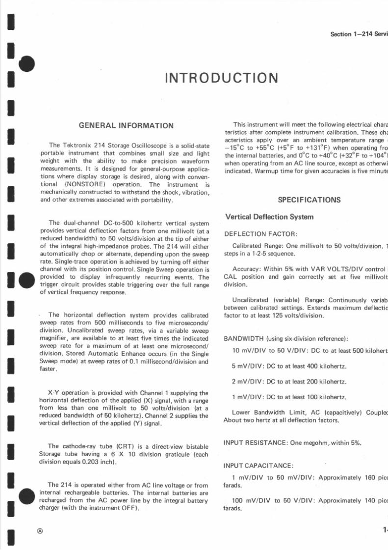
ektronix 21 4 StorageOscilloscope.
5/14/2018 Tektronix 214 Manual - slidepdf.com
http://slidepdf.com/reader/full/tektronix-214-manual 7/95
tIII
I
fo
I
f.The cathode-rayube (CRT) is a direct-viewbistable
Storage ube having a 6 X 10 division graticule eachdiv is ion quals .203 nch) .
Th e 214 is operated ither ro m AC linevoltage r frominternal rechargeable atteries.The internal batteriesarerechargedrom the AC power line by the integralbatterycharger with he instrumentOFF).
@
I N T R O D U C T I O N
GENERALNFORMATION
Th e Tektronix 214 StorageOscilloscopes a solid-stateportable nstrument hat combinessmall size and lightweight with the ability to make precisionwaveformmeasurements.t is designedor general-purposepplica-tions wheredisplay storage s desired, longwith conven-t ional (NONSTORE) operat ion. The instrument ismechanicallyonstructedo withstand he shock, ibration,and otherextremes ssociated ith portability.
I Th e dual-channelDC-to-500kilohertz verticalsystemI provides erticaldeflection actors rom one millivolt (a t a
reducedbandwidth) o 50 volts/division t the tip of either
I of the integralhigh-impedancerobes.The 214 will eitherf automaticallychop or alternate, epending pon he srueep-
rate.Single-trace peration s achieved y turningoff eitherchannelwith its position ontrol.SingleSweep peration s
I O iffixl,,.ff,::lil"Jl:ffJ1,H",.fij;'#,^'J?lf,Ji:of vertical requency esponse.
I The horizontal deflection system provides calibrateds1,\reepates from 500 millisecondso five microseconds/
I division. Uncalibrated ,\reep ates,vi a a var iable$/eepI magnifier, re availableo at least ive t imes he indicatedI sliveep ate for a maximum of at leastone microsecond/
. division.StoredAutomatic Enhance ccurs in th e SingleI Sweepmode)at sl,eep ates f 0.1 millisecond/divi sionnd
t faster.
I X- Y operation s providedwith Channel supplyingheI horizontal eflectionof the applied X) signal, i th a range
from less han one millivolt to 50 volts/division at a
I reduced andwidthof 50 kilohertz).Channel supplieshe
Ivertical eflection f the applied Y) signal.
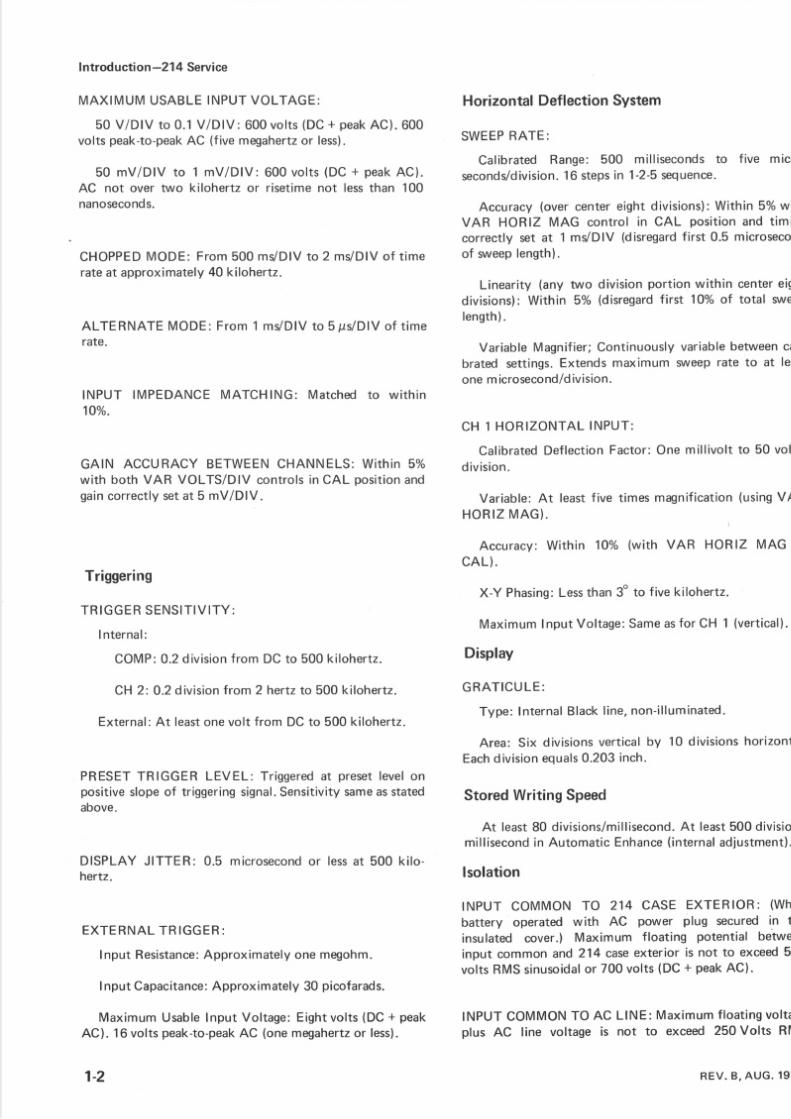
This nstrument i l l meet he ollowingelectrical harateristicsafter complete nstrumentcalibration.Thesechaacteristicsapply over an ambient temperature ange o-15oC to +55oC +5"F to +131"F)when operat ingrothe nternal atteries, nd OoC o +40"C (+32"F o +104"Fwhen operating rom an AC line source, xceptasotherwiindicated.Warmup ime or givenaccuraciess iv e minute
SPECIFICATIONS
Vertical DeflectionSystemDEFLECTION ACTOR:
CalibratedRange:On e mil l ivolt o 50 volts/division.steps n a 1-2-5 equence.
Accuracy:Within 5%with VAR VOLTS/DlV control CAL position and gain correctly set at five millivoltd iv is ion.
Uncalibrated variable)Range:Continuouslyvariabbetweencalibratedsettings.Extends maximum deflectiofactor to at least125 volts/division.
BANDWIDTH using ixdivision eference):
10 mV/DlV to 5 0 V/DlV: DC to at least 00 kilohert
5 mV/DlV: DC o at least 00 kilohertz.
2 mV/DlV: DC o at least 00 kilohertz.
1 mV/DlV: DC o at least10 0kilohertz.
Lower Bandwidth Limit, AC (capacitively) oupleAbout two hertzat all def ection actors.
INPUTRESISTANCE: nemegohm, i th in 5%.
INPUTCAPACITANCE:
1 mV/DlV tofarads.
100 mV/DlVfarads.
50 mV/DlV: Approx imately 60 pic
to 50 V/DlV: Approximately14 0 pico
Section1-214 Serv
1-
5/14/2018 Tektronix 214 Manual - slidepdf.com
http://slidepdf.com/reader/full/tektronix-214-manual 8/95
Introduction-21 4 Service
MAXIMUMUSABLE NPUTVOLTAGE:
50 V/DlV to 0.1V/DlV: 600vol ts DC+ peakAC). 600volts peak-to-peak C (fivemegahertz r less).
50 mV/DlV to 1 mV/DlV: 600 vol ts DC+ peakAC).AC not over nruokiloherlz or risetimeno t less han 100nanoseconds.
CHOPPED ODE:From500mVDIV o 2 ms /D lV f t imerateat approximately 0 kilohertz.
ALTERNATEMODE:From1 mVDIV o 5 ps lD lVof t imerate,
INPUT IMPEDANCEMATCHING: Matched o w i th in1Oo/o.
GAIN ACCURACYBETWEENCHANNELS:Wi th in 5%with both VAR VOLTS/DIV controls n CAL position ndgaincorrectly etat 5 mV/DlV.
Triggering
T RIG G E R E NS IT IV IT Y :
Internal :
COMP: .2div is ionrom DC o 500 k i loher tz .
CH 2: 0. 2division ro m 2 hertz o 500 kilohertz.
External:At least nevolt from DC o 500 kilohertz.
PRESET RIGGER LEVEL: Tr iggered t preset evelonpositive lopeof tr iggering ignal. ensitivity ame sstatedabove.
DISPLAYJITTER: 0.5 microsecondr less t 500 k i lo-hertz.
E X T E RNA L RIG G E R:
lnput Resistance:pproximately nemegohm.
InputCapacitance:pproximately 0 picofarads.
MaximumUsable nput Voltage:Eightvolts (D C+ peakAC). 16voltspeak-to-peakC (onemegahertz r less).
1-2
Horizontal Deflection System
SWEEP ATE:
Calibrated Range: 500 milliseconds o five micseconds/division.6 steps n 1-2-5 equence.
Accuracy overcentereightdivisions):Within 5% wi
VAR HORIZ MAG control in CAL pos i t ionand t imicorrectly set at 1 mVDIV (disregardirst 0.5 microsecof wveepength).
Linearity (any trruo ivisionportionwithin centereigdivisions):Within 5% (disregardirst lOo/o f total srulength) .
VariableMagnifier;Continuously ar iable etween abrated settings.Extendsmaximum svveepate to at leone m crosecond/dvision.
CH 1 HO RIZ O NT A LNP UT :
CalibratedDeflectionFactor:On e mil l ivolt o 50 vold iv is ion .
Variable:At least ive timesmagnificationusingVAH O R I ZM A G }
Accuracy:With in 1O%owith VAR HORIZ MAG CA L) .
X- Y Phasing: es s han 3o o five kilohertz.
Maximum nputVol tage: ame s or CH 1 (vert ical)
Display
G RA T ICU E:
Type: nternal lack ine,non- i l luminated.
Area: Six divisions erticalby 10 divisions orizonEach iv is ion quals .203 nch.
Stored Writing Speed
At least80 divisions/millisecond.t least500 divisiomi l l isecondn Automat icEnhanceinternal d jus tment
lsolation
fNPUT COMMON TO 214 CASE EXTER OR (Wh
battery operated with AC power plug secured n th
insulated cover.) Maximum f oating potential betweinput common and214 caseexterior is not to exceed50volts RMSsinusoidal r 700 volts DC + peakAC).
$i,'.'?ilyli,H: :$=#ff:ä,"Jläl;:?REV. ,AUG. 9
5/14/2018 Tektronix 214 Manual - slidepdf.com
http://slidepdf.com/reader/full/tektronix-214-manual 9/95
II s inusoidalor L4 t imesheAC ine ol tagelus DC+ peak
: O
AC) snot o exceed50volts
I AC Operation
Due to the capacitive line input circuit, sudden volt-age changes may cauffi damaging input currenttransients. Avoid operating this instrument fromsguare-wave nverter supplies, or other sources thatproduce large voltage transients.
L INEVOLTAGERANGE:
StoredMode: 110 to 126 voltsAC. Batteries an not bechargedduring AC ope ration. nstrumentcan be operatedbetween 104 and 110 voltswith resulting lowdischarge finternalbatteries.
NonstoreMode: 104 o 126voltsAC . Instrument anbeoperatd without resultingdischarge f internal batteries.
LfNE FREOUENCY:58o 62hertz.
NOTE
Refer to Option and Maintenance information forother Line Voltagesand Frequencies.
MAXIMUM POWERCONSUMPTION: hreewatts or lessat 126 volts,60 hertz.
l o
IItI
II
I
tItIII
Introd ucti on -21 4 Serv
InternalBatteryOperation
BATTERIES: 0 rechargeables ize, ickel-cadmiume
CHARGE TIME (from AC line) : 8 hours or fu l l ch(instrument ff during charge ycle).
POWER (BATTERY) INDICATOR: When ext inguiindicates pproximatelyive minutes f scope peratingleft in th e batteries.
BATTERYEXCESSIVE ISCHARGE ROTECTIONstrumentoperation utomaticallynterruptedwhen batcharge rops o 10 volts,+0.5volt.
TYPICALOPERATING IME (atmaximum race ntenafter ull charge ycleat +20oC o +30oC):
NONSTOREMode: 3.5 to five hours.Longest peratime provided t lower race ntensity.
STOREMode: 2.5 to 3.5 hours.Longest peratingprovided t lower race ntensity.
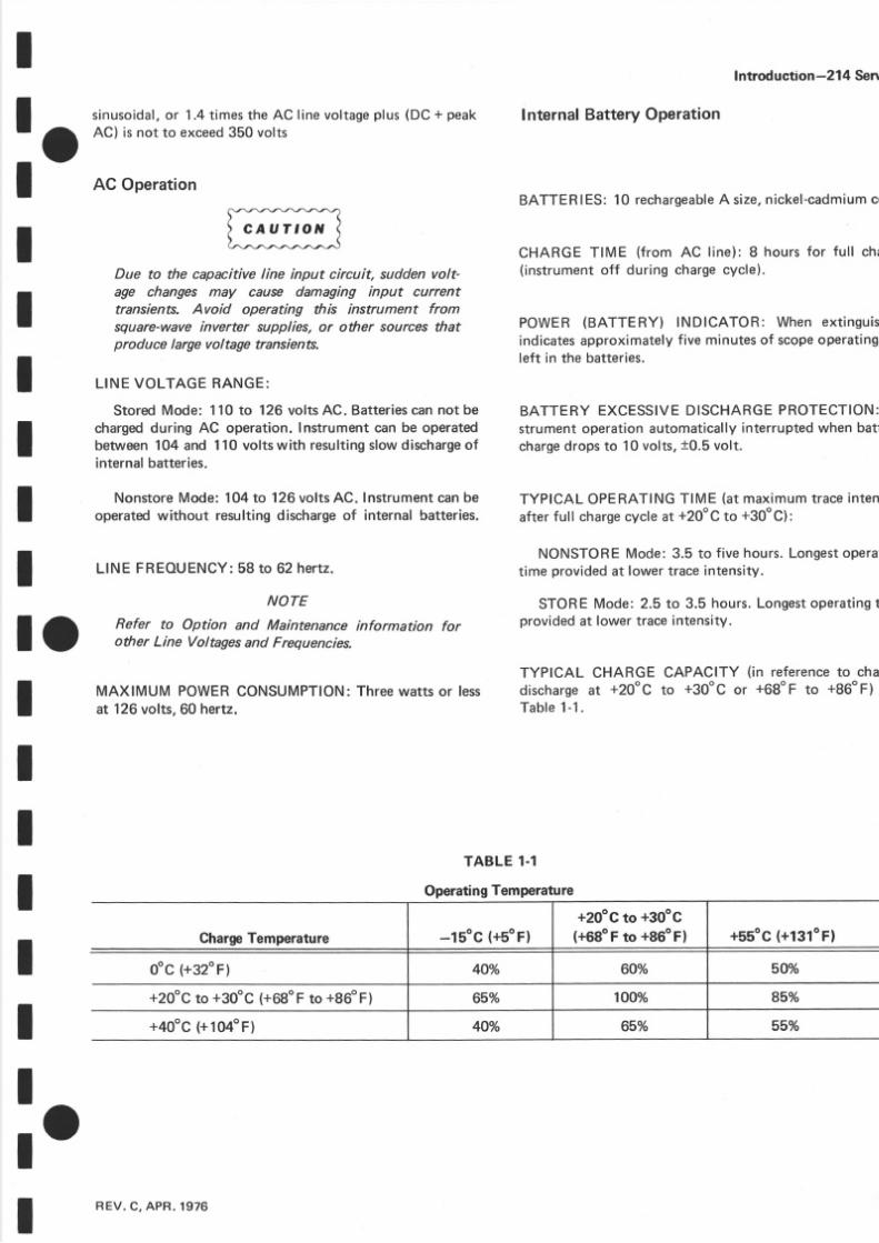
TYPICAL CHARGE CAPACITY (i n referenceo chadischarge t +20oC to +30"C or *68oF to +86oF)Table1-1
TABLE1-1
Operating emperature
ChargeTemperature _lsoc (+soF)+20"G o +30"c(+69"F o +86oF) +55oC +131oF)
SOYooc (+32"F) 4OYo 6OYo
+20"c to +sgog (+68oF o +86oF) 65Vo 100% 85Yo
+40oc +104"F) 40o/o 650/o 55Yo
l oREV.C,APR.1976 1

5/14/2018 Tektronix 214 Manual - slidepdf.com
http://slidepdf.com/reader/full/tektronix-214-manual 10/95
Introducti on-214 Service
Environmental
Temperature:
Operating rom Batteries,15"C to +55oC +5oF o+ 1 3 1 " F )
Operating rom AC Line, 0"C to +40oC (+32oF o+104"F)
Non-Operating,40"C to +ggog (-40"F to +140"F)
Al t i tude:
Operating, o 25,000 feet (maximumoperating em-peraturedecreased y loC per 1,000 eet above 15,000feetl.
Non-Operating,o 50,000 eet.
Humidity (operatingand non-operating): ve cycle
l;,'r1rl''.ätJ:e'o/oelativeumiditvn rererenco
Shock (operatingand non-operating): estedwith nrushocksat 150g, one-halfsine, wo millisecond uratioeachdirectionalongmajoraxes.
Physical
WEIGHT (without accessories):.5 pounds 1.6 kilogram
DIMENSIONS measuredt maximumpoints):
Height;3. 0 nches 7. 6centimeters)
Width: 5.25 nches 13.2centimeters)
Depth:9.5 inches 24.1centimeters)
@4

5/14/2018 Tektronix 214 Manual - slidepdf.com
http://slidepdf.com/reader/full/tektronix-214-manual 11/95
I
IIII
II
IIIII
: O
l o
Itl o
Section2-214 Ser
F U N C T I O N S F C O N T R O L S
A N D C O N N E C T O R S
Controlsand connectorsnecessaryor operation of the 214 are ocatedon the front paneland on the right sidepansthe instrument. A bri€f descriptionof eachcontrol and connector sgivenhere.
Front PanelControls NOTE
After sustained use (30 min or more) of the instrument in the Store mode with nothing written, thewriting speed may be reduced. lt may be improvedby leaving the CRT target fully stored for five to tenminutes. This procedure may be repeated to refredthe target in applications reguiring maximum storewriting rate.
STORE-whenpressed,he CRT operatesn the Stomode. With the button out, the CRT operates n convent ional ,ONSTORE, ode.
ERASE-momentarycontactswitch, hat when pus
an dreleasedrases Storeddisplay ro m th e CRT.
VOLTS/DlV-selects he verticaldeflection actor1-2-5 sequence verticalVARiable must be in the Cposition or indicated eflection).
READY Light-indicates sweephas been resetand asingle isplaywill be presented pon eceipt f an adequatetrigger ignal.
SINGLE SWP-whenpressed,he sweep peratesn theSingleSweepmode. After a sweep s displayed, urthersweepscannot be presented nti l the RESET button ispressed.
RESET-whenpressed nd in the SingleSweepmode,asingledisplay will be presented fter correct tr iggering.After the sweep s completed, he RESETbutton must bepressed gainbeforeanothersweep an be displayed.
REV. ,AUG. 974
POWER (BATTERY)-red light to indicatewheninstrument s on. When ight extinguishes,atterycharlow an dabout ive minutes f operatingife remains.

5/14/2018 Tektronix 214 Manual - slidepdf.com
http://slidepdf.com/reader/full/tektronix-214-manual 12/95
Functionsof Controlsand Connectory2l4 Service
SidePanelControlsand Gonnectors
INPUT COUPLING-selectsmethodused o coupl e hechannel nput signal o the verticalamplifiersystem.
AC-DC componentof input signal s blocked.Lowfrequency imit {- 3 dB point} sabout2hertz.
GND-vertical amplifier inpüt circuit is grounded.The applied signal s connected o ground through alargevalveresistor o provide a precharge ath for the
AC input coupling apacitor.DC-all components f the input signalare passedo
the verticalamplifiersystem.
STEP ATTEN BAL-screwdriveradjustment o balancethe verticalsystem or minimum traceshift when changingdeflection actors,
Vertical POS-controls the vertical position of theappropriate race.Detent urns he channelOFF.
VAR VOLTS/DlV-provides a continuouslyvariabledeflection factor between the calibrated settings of theVOLTS/DIV switch.
VERT GAIN-screwdriveradjustment o set he gainofthe entireverticalsystem.
AUTO PREsET-screwdriver adiustment to set thePRESET riggerpoint fo r AUTO sl,\reepperation.
TRIG SOURCE-selectshe source f the triggersignal.
COMP-sweep s triggered rom a DC-coupled ampleof the verticalsignal fter the verticalswitching.
CH 2-sweep is triggered rom an AC-coupled ampleof the CH 2 verticalsignalbefore he verticalswitching.
EXT-sweep is triggered rom the DC-coupled ignalappliedo th e EXT TRIG bananaack.
LEVEL/SLOPE-selects he amplitude point and slopof the triggersignalon which the sweep s triggered.Whethe indicator dot is to the left or center, the sweep triggeredon the positivegoing lopeof the triggersignal; othe right of center,on the negative€oing lope.When heLEVEL/SLOPE control is set to the AUTO PRESEdetent, he srueeps automatically riggered t a preset eveon the positive{oingslope.
INTENs|TY-controlsbrightnessf th e CR T display.
SWPCAl-screwdriver adiustment o providecalibratesvveepiming.
POwER-controls power to the instrument. Doesnointerrupt charging urrent o the internalbatterieswhen heinstrument sconnectedo an AC line voltage.
FOCUS-screwdriverdiustment o obtaina welldefineddisplay.
VAR HORIZ MAc-provides continuously variabsweepmagnification o a maximum of at least ive timethe weep rate ndicated y the SEC/DIVsruitch.
HORIZ GA|N-screwdriver diustment o set the basgainof the horizontalsystem.
HorizontalPOS-controls he horizontalpositionof thetrace.
SEC/Dlv-selects he sweep ate (VAR HORIZ MAGmustbe in CAL detent or indicated weep ate).
EXT TRIG-banana ac k to establish ommongrounbetween he 214 and the external signalsourceor equipment under est.
@-2

5/14/2018 Tektronix 214 Manual - slidepdf.com
http://slidepdf.com/reader/full/tektronix-214-manual 13/95
I
_ oI
IIIt
III O
IIl o
I
IIII
Section 3-214 Serv
sEci l0N
MAITUTEIUANGEIntroduction
This section of the manual contains maintenanceinformation or use n preventivemaintenance,orrectivemaintenance,r troubleshooting f the 214.
PREVENTIVE AINTENANCE
General
Preventivemaintenanceconsists of cleaning, visual
inspection, lubrication, etc. When performed on aregularbasis,preventivemaintenance an prevent nstru-ment breakdownan d may improve he reliabilityof thisinstrument. Th e severity of environment o which th e214 is subjectedwill determine he frequency of main-tenance. A convenient time to perform preventivemaintenances preceding ecalibration f the instrument.
Avoid the use of chemical cleaning agents whichmight damage the plastics used in this instrument.Avoid chemicals which contain hydrochloric acid,
sodium hydroxide, or sulfuric acid.
Cleaning
The 214 should be cleaned as often as operatingconditions equire.Accumulation f dirt in the nstrumentcan cause omponentbreakdown.
The high-impact lasticcovers rovideprotectionagainstdust in the interior of the instrument.Loosedustaccumu-lated on thesecovers an be removedwith a soft cloth orsmallbrush.Th e brush s alsouseful or dislodging irt onand around he exteriorcontrols.Dirt that remains an beremovedwith a soft cloth dampened n a mild detergent
and watersolution.Abrasive leaners houldnot be used.
Cleaninghe interiorshouldonly be occasionally eces-sary.The bestway to clean he interior is to blow off theaccumulated ust with dry, low-velocityair. A soft-bristlebrushor a cotton-tippedapplicator s useful or eleaningnnarrowspaces r fo r cleaningmoredelicate omponents.
Lubrication
Generally, here are no components n the 21 4 tharequire lubrication. No lubrication should be used othe contacts or rotary parts of the rotary switches. Threliability of potentiometers hat are not permanensealedcan be maintainedby lubricationwith a lubricathat does not affect electrical characteristics(e.Tektronix Part No. 006-2574-00).Do not over-lubrica
Visual nspection
The 214 should be inspectedoccasionally or sudefects as broken connections, mproperly seated ranstors, damaged ircuit boards,and heatdamaged arts.Thcorrectiveprocedure or most visibledefects s apparehowever, particular care must be taken if heatdamagcomponents re found. Overheating sually ndicates thtrouble in the instrument; herefore, orrectinghe causethe overheating s important to preventrecurrence f thdamage.
CRT CareTo prolong the useful life of the Storagescreen, h
following precautions hould be observedwhen operatithis nstrument:
1. Care must be taken in the degreeof writing-beaintensity that is used,particularlywhen usingslow sweerates,X-Y displays,or the STORE mode. Too-highbeaintensitymay permanently amagehe CRT screen.
2. Avoid repeated seof the sameareaof the screena particulardisplay is beingStoredrepeatedly, hange h
verticalposition occasionally o use other portionsof thdisplayarea.
3. Do not leave Storeddisplayon the screenwhen t no longer eeded.
4. Operate n th e NONSTOREmode unlessStoragerequired.
C A U T ' O N
3-1EV.C,NOV.1977

5/14/2018 Tektronix 214 Manual - slidepdf.com
http://slidepdf.com/reader/full/tektronix-214-manual 14/95
Main enan e 21 4 Servi e
Recalibration I nformation
To ensureaccuratemeasurements.heck he calibrationof this instrumentafter each 1000 hoursof operation, reverysi x months f used nfrequently. n addition, eplace-ment of componentsmay necessitateecalibrationof theaffected circuits. Th e calibrationprocedure an also behelpful in localizing ertain roubles n th e instrument. n
somecases,minor troublesmay be revealed r corrected yrecalibration.
Disassemblynstructions
To gainaccesso the interiorof the nstrument, nwindboth probecordsand he powercord rom the instrument'sprobewrap at th e rearof the214.
NOTE
The arrows on the probe wrap indicate the proper
direction to wrap the probes and power cord. SeeFig. 3-1.
Remove he five screws n the bottom cover of thinstrument.Se eFig.3-2. Separatehe bottom cover ro
th e instrumentan d lay it aside.Th e PowerSupply (A-
circuit board, an d the batteries,ca n be lifted up anpivoted out of the way. Most of the internalworkingsoth e instrument renow accessibleor maintenance.
I
YELLOW ROUND LIP S
POSIT IONEDERE EFOREINA LWRAP FTHEPROBE
Fig.3-1. Proper method fo r wrapping probes.
3-2 REV.APR 1974 @
5/14/2018 Tektronix 214 Manual - slidepdf.com
http://slidepdf.com/reader/full/tektronix-214-manual 15/95
I
: ot
IIII
II
SCREWSECURINGBOTTOMCOVER
SCREWS ECURINGS I D E P A N E L
SCREWSECURINGSINGLE WEEP OARD
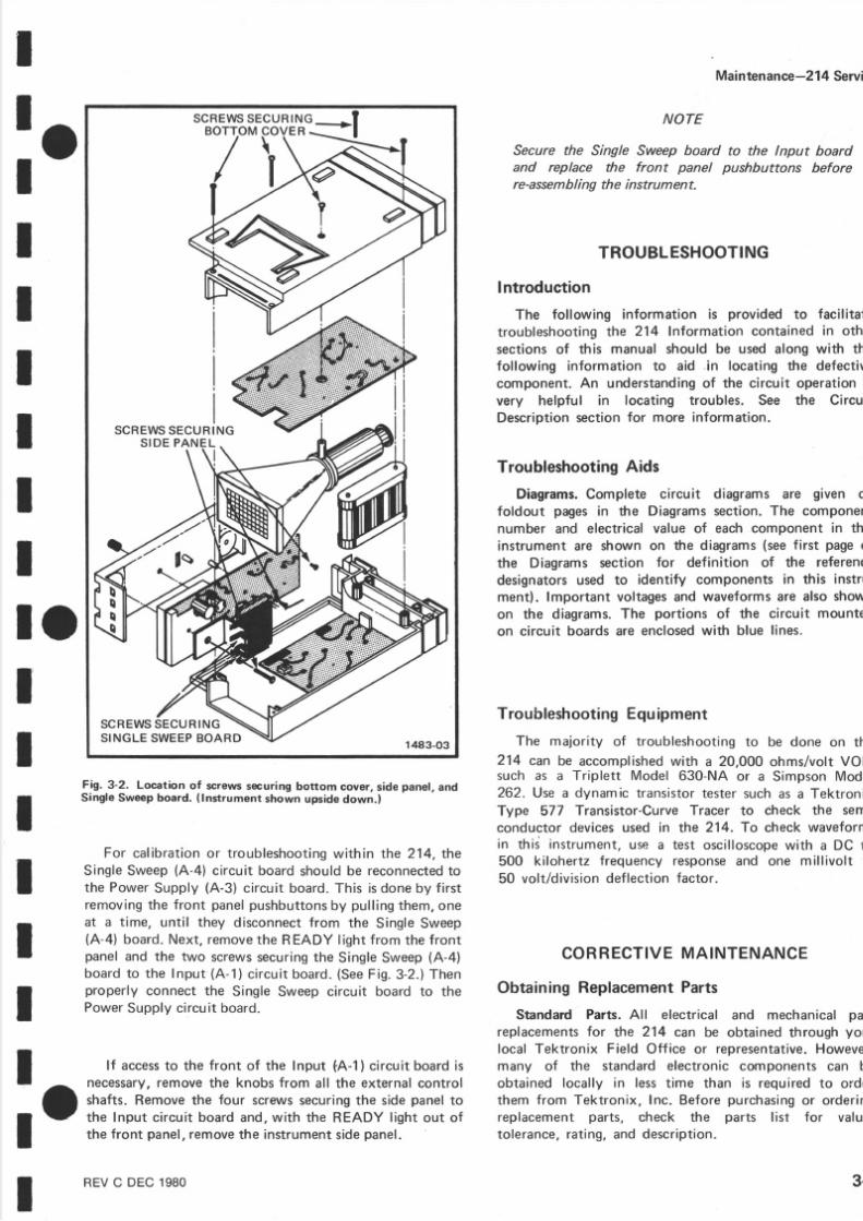
Fig. 3-2. Locationof screws ecuringbottom cover,sidepanel,andSingleSweep oard. lnstrument hownupside own.)
For ca l ib ra t ion or t roub leshoot ingwi thin the 214, theSingle Sweep (A-4) circuit board should be reconnected othe Power Supply (A-3) circuit board. This is done by firstremoving th e front panel pushbuttons by pull ing them, on eat a t ime, unti l they disconnect from th e Single Sweep(A-4) board. Next, remove he READY l ight from the frontpanel and the tw o screwssecuring he Single Sweep (A-4)
board to the Input (A-1) c i rcu i t board. (SeeF ig .3-2 . ) Thenproperly connect the Single Sweep circuit board to th ePower Supply circuit board.
Maintenan e-214 Serv
NOTE
Secure the Single Sweep boardand replace the front panelre-asseml ng th e instrum ent.
to the lnput boardpushbuttons before
TROUBLESHOOTING
Introduction
Th e following information is provided to facilitatroubleshooting he 21 4 Information contained n othsectaons f this manual should be used along with thfollowing information to aid .i n locating he defecticomponent.An understanding f the circuit operation very helpful in locating troubles. See th e CircuDescription ection or more information.
Troubleshooting ids
Diagrams.Complete circuit diagrams are given ofoldout pages n th e Diagrams ection.The componenumber and electrical value of each component in thinstrumentare shown on the diagrams se e irst pageothe Diagrams section for definition of the referendesignatorsused to identify components n this instrmentl. lmportant voltagesand waveformsare also showon the diagrams. he portions of the circuit mounteon circuit boardsar e enclosed ith blue lines.
Troubleshooting Equipment
Th e malority of troubleshooting o be done on th214 can be accomplishedwith a 20,000 ohms/volt VOMsuch as a Triplett Model 630-NA or a SimpsonMod262. Use a dynamic transistor estersuchas a TektronType 577 Transistor-Curve racer to check the semconductor devicesused in the 214. To check waveformin thid instrument,use a test oscilloscope ith a DC t500 kilohertz frequency response nd one millivolt t50 volt/division eflection actor.
CORRECTIVEMAINTENANCE
Obtaining ReplacementParts
Standard Parts. All electrical and mechanical pareplacements or th e 214 ca n be obtained through you
local Tektronix Field Office or representative. Howevemany of the standard electronic components can bobtained locally in less t ime than is required to ordethem from Tektronix, Inc. Before purchasing or orderinreplacement parts, check the parts l ist for valutolerance, rating, and description.
l oIIIIIII l f accesso the front of the Input tA- l)c ircuit board sr
a l^".*'J#:träJi:1":nJ:Hl';:':ilJ';::lllI - the Input circuit boardand,with the READY light out of
tthe front panel, emove he instrument idepanel.
RE VC DEC 1980 3-

5/14/2018 Tektronix 214 Manual - slidepdf.com
http://slidepdf.com/reader/full/tektronix-214-manual 16/95
Maintenan e 21 4 Service
NOTE
When selecting replacement parts, it is importantto remember that the physical size and shape of acomponent may affect its performance in theinstrument. All replacement parts should be directreplacements unless it is known that a differentcomponent will not adversely affect the instrument
performance.
Special Parts. In addit ion to the standard electronic
components, some special components are used in the214. These components are manufactured or selected byTektronix, Inc. to meet specif ic performance require-ments, or are manufactured for Tektronix, Inc. in ac -cordance with our specif ications. Most o f the mechanicalparts used in this instrument have been manufactured byTektronix, Inc. Order al l special parts directly from your
local Tektronix Field Office or representative.
OrderingParts.When ordering eplacement arts roTektronix, Inc., include he follovrüingnformation:
1 Instrumentype.
2. lns t rument er ia lnumber .
3. A descr ipt ionof the part ( i f e lec tr ical , nc lu
c ircui t number) .
4. TektronixPart Number.
W A R T ' T G
Disconnect the instrument from any externalpower source before replacing components.
Component Replacement
GircuitBoard Replacement.f a circuit board
damaged eyond repair, he entire assemblyncludingasolderedon components an be replaced.Part numbear e given n the Mechanical artsList for the completewired board.
"o rrraro*/
ili-)
ffilBASE2ilil EMITTER
SCREW OUNTED
BASE1(}388
N.CHANNEL NIJUNCTION
coLLEcro-ffiMrrrERoLLEcro-,fiMrrrERoLLEcro-ffiMrrrER
BASE eÄseBASE
TRANSISTORS
I N D E X I N D E X
,afAT E S OURCE
D R A | N1 4
GATE
D R A I N
SO URCE 1
ru-r^J-J4 - P t N
D U A L I N T E G R A T E DC ] R C U I T S
16-PtN
1483 -04
EM TTER
I
34
Fig. 3-3. Lead configurations of semiconductors used in this instrument.
REVE DEC19

5/14/2018 Tektronix 214 Manual - slidepdf.com
http://slidepdf.com/reader/full/tektronix-214-manual 17/95
I
: oI
IIII
II
Transistor Replacement.Transistors should not bereplacedunlessactually defective. f removed rom, theirsocketsduring routine mainte nance, eturn them to theiroriginal sockets. Unnecessaryeplacementof transistorsmay affect the callbration of this instrument. Whentransistorsare replaced, heck the operationof that partof the instrumentwhich may be affected.
Replacement transistors strould be of the originaltype or a direct replacement.Fig. 3-3 shows the leadconfiguration of the transistorsused in this instrument.Some plastic case transistorshave lead conf gurationswhich do not agreewith those shown here. lf a transis-tor is replaced by a transistor which is made by adifferent manufacturer than the original, check themanufacturer's basing diagram for correct basing. Al ltransistor sockets in this instrument are wired for thebasingused or metal-caseransistors.
An extracting ool shouldbe used o remove he 14-and16'pin flat integratedcircuits to prevent damage o thepins. f an extracting ool is not available hen removing
one of these ntegrated ircuits, ull slowly and evenlyonboth endsof the device.Avoid having ne end of the l.C.disengagerom the socketbefore he other,as he pinsmaybe damaged.When replacing semiconductors, ey thesemiconductor'sndex with that of the socket.Failure odo sowill result n damaged omponents.
Maintenan ,e-21 Servi
Due to the capacitive power line circuit, suddenvoltage changes may cause damaging current tran-sients.Avoid operating this instrument from square
wave inverter supplies, or other sources that producelarge vol age transients.
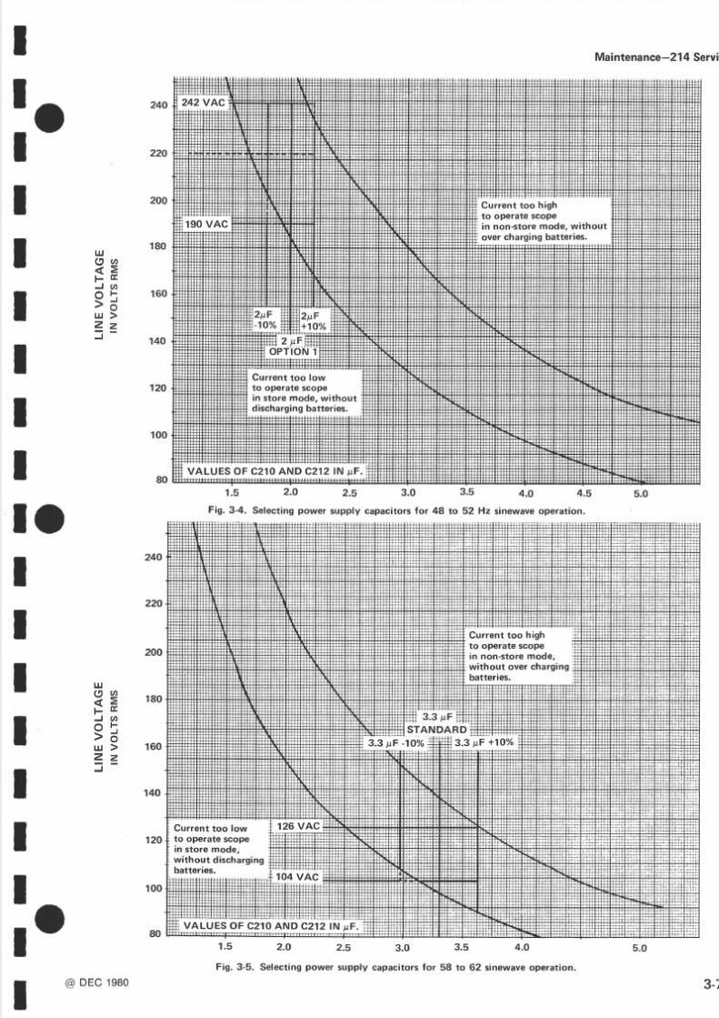
Selection f capacitor alues or other ine voltagefrequency ombinationss illustrated y thegraphsn F3-4 and 3-5. For example, f th e instrument s to be opated on a 60 Hz l ine, he graph n Fig.3 '5 i l lus t rateminimum and maximum ine vol tage imits ,wi th resto the 3.3 pF capacitancealues, or properoperatioth e instrument. t alsoprovides nformation or selecvalues f C210 and C212 fo r other ine voltages. ig.provides50 Hz information.Thesecapacitors houldselectedro m a type suitable or AC operation ndvolt
rat ingsshould be at least1.414 imes hevalue
of appl ied ine vol tage.
C2O4and C215 values must be changed rom nominalvalue onlywhen the instrument s to be operafrom other ha n 115 V50 Hzor 115V 60 Hzpower ine.24OV5O Hz operation,C2O4and C215 shouldbe replawith .OO1 F 3kV capacitors.
Selectable Gomponents. Resistor R388 valueselected or a switchingunblanked race height of no mthan 1.5div is ionsor each hannel ndminimum nten
changewhen changing weepspeeds ro m 5 ms o 2 mThe valueof R388 s selectedro m a rangeoI 27O,3OO330 O as follows:
1. Installa 27OO resistor or R388, urn the 214set SEC,/DIVto5 s, andse t NTENSITYto axim(fullyclockwise).
2. The raceswill show as dots.Set CH 1 POS o plthe CH 1 dot o the top horizontal raticule in easet CH 2 POS o place he CH 2 dot to the bothorizontal raticule ine.
Check ha t no more han 1.5divisions f unblantrace elftendsvertically rom each dot.
lf each unblanked trace exceeds 1.5 vertdivisions,urn offthe214, nstallthenext argerfo r R388, echeckandrepeatsteps2through 4 uunblanked races are no more than 1.5 divisih igh whi le maintain ingminimum ntens i ty hawhen switching sweep speed rom 5 ms to 2 m
I o il: :f,j#r 'ilr"[+,Fj:r:'"l;#i#replacement arts.
Power Supply Gapacitors.When operating he instru-ment from powersources ther than 115 VA C 60 Hz, t is
necessaryo changehe electrical alueof capacitors 210and C212 o maintain ropercurrent eve.lso the batteries.Refer o Table3- 1 fo r th e correct alues f capacitanceorthree of the more commonly used ine voltage/line re -quencycombinat ions.
TABLE3.1
POWER UPPLY APACITORS
III
i lIIIl o
3.
NominalPowerLineVoltage/Frequency
110 o 126VAC58 to 62 Hz(Standard)
90 to 110 VAC48 to 52 Hz(Opt ion2)
224 to 250 VAC48 to 52 Hz(Opt ion )
c210- c212
3.3pF, +10%,2O0VDC TektronixPN 285-0925-00
4 ttF,+1O%,200VDC TektronixPN 285-0935-00
2 t tF,+1oo/o,4OOVDC TektronixPN 285-0933-00
RE VF DEC1981
4.
3-
5/14/2018 Tektronix 214 Manual - slidepdf.com
http://slidepdf.com/reader/full/tektronix-214-manual 18/95
Maintenan e-214 Service
RecalibrationAfter Repair
After any electricalcomponent has been replaced, hecalibration of that particularcircuit should be checked,as well as the calibration of other closely relatedcircuits. Since the power supply affects all circuits,calibrationof the entire instrumentshould be checked fwork has beendone in the supply.
I nstrument Repackaging
lf th e Tektronix nstruments o be shippedo a TektronixServiceCenter or service r repair,attacha tag showing:owner (wittr address) nd he nameof an ndividual t yourfirm that can be contacted,complete nstrumentserialnumberan da description f the serviceequired.
Save nd re-usehe packagen which your instrumentwashipped. f th e originalpackagings unfit fo r us eor noavailable,epackagehe nstrument s ollows:
Surround he instrumentwith polyethylene heetingprotect he finish of the instrument.Obtain a cartonocorrugated ardboardof the correctcartonstrengthanhaving nsidedimensions f no less ha nsi x inchesmorthan the instrument imensions. ushion he instrume
by tightly packing hree nches f dunnage r urethafoam between arton and nstrument, n all sides. ecartonwith shippingap eor industrial tapler.
The carton est strength or your instrument s 200 pound
3-6 REV E DEC19
5/14/2018 Tektronix 214 Manual - slidepdf.com
http://slidepdf.com/reader/full/tektronix-214-manual 19/95
I
: oI
IIII
II
UJg sF t rJ tt,
o t> öu J >Z z
Maintenan e-214 Serv
120
lrJs 9d zl j E!
J O
e 5- oL U >
V =J
1.5 2.O 2.s 3.0 3.5 4.o 4.s
1.5 2.O 2.5 3. 0 3.5 4.0
Fig.3-5. Selecting owersupply capacitorsor 58 to 62 sinewave peration.
l oIIIIIIIl o
@DEc e8o
180
160
100
18 0
140
120
: in non-store mode, without
Current to o lo wto operate scopein store mode, withoutdischargingbatteries.
Fig. 3-4. Selecting power supply capacitors for 48 to 52 Hz sinewaveoperation.
Current to o highto operate scopein non-store mode,without over chargingbatteries.
Current to o lo wto operate scopeanstore mode,without dischargingbatteries.
10 0
3-7

5/14/2018 Tektronix 214 Manual - slidepdf.com
http://slidepdf.com/reader/full/tektronix-214-manual 20/95

5/14/2018 Tektronix 214 Manual - slidepdf.com
http://slidepdf.com/reader/full/tektronix-214-manual 21/95
I
: oI
IIII
I
General
To ensure nstrumentaccuracy, heck he calibrationofthe 214 every1000hoursof operation, r everysix monthsif used infrequently. Before complete calibration, hor-oughlycleanand inspect hi s instrument s outlined n th ePreventiveMaintenanceection.
Tektronix, Inc.,provides omplete nstrument epairand
recalibration t local Field ServiceCenters nd he FactoryServiceCenter.Contact your localTektronix Field Officeor representataveor further information.
C A L I B R A T I O N
TABLE 4-1
Test Equipment
TESTEOUIPMENT EOUIRED
The following test equipmentand accessories,r theequivalent, are required for complete calibration of th214. Given specificationsor the test equipmentare thminimum necessaryor accurate alibration.Therefore,hspecifications f any test equipment must either meet oexceed hose isted below.All testequipment sassumedbe correctly calibrated and operating within the listespecifications.Detailedoperating nstructions or the te
units are not given in this procedure. Refer to thinstruction manual for the test equapmentf more infomation s needed.
SpecialCalibrationFixtures
SpecialTektronix Calibration ixtures are used n thprocedure nly where hey facilitate nstrument alibratioThese special calibration fixtures are available fromTektronix, Inc. Order by part number hrough your locTektronix FieldOfficeor representative.
Section 4-214 Servi
Example
Triplett Model630-NA.
SimpsonModel262.
a. GeneralRadio1310-BOscillat
a. .Tektronix PartNo. 067-0502-0
r Completion of each step in the Calibrationprocedureensures that this instrument meets th e electrical
I O ilfff l,,"#l,älJo,, il,"''}Il,?y;lg-*J""[äbefore an adjustment is made. For best overall
I performance,make each adiustment o the exact settingf even f th e CHECK- step swithin the allowableolerances.I
IIII
Description
1. DC Voltmeter
2. Low-FrequencyCo nstant-AmplitudeSignalGeneratorI
I l;.1?lilll*of;'0".
l r o@
Range, zero to 1000 volts;accuracy,within 3o/o; nputimpedance, 0,000 O/volt.
Power Supply output levelchecks,CRT Grid Bias,Stor-age Level adiustments. erti-cal and horizontal centeringadjustments.
Frequency,one kilohertz to500 kilohertz;output ampli-
tude, at least200 millivolts.
StorageEnhance eveladjust-ment . Ver t ica l ampl i f ie rbandwidth and triggeropera-tion checks.
Ampf tude accuracy, O.25o/o;signal amplitude, five mil l i-volts to 100 volts; outputsignal, one-kilohertzsquarewave.
Vertical and horizontalgainchecks nd adjustments.
+

5/14/2018 Tektronix 214 Manual - slidepdf.com
http://slidepdf.com/reader/full/tektronix-214-manual 22/95
Description Minimum Specifications Usage Example
4 . S q u a r e - W a v eGenerator
F equency, one kilohertz;risetime,100 nanosecondsrfess;output amplitude, o.4volt to 40 volts.
Vertical amplifier compensa-tion checksand adiustments.
a. TektronixType 106Square-WaGenerator.
5. Time-Mark Gen-erator
Marker outputs, five micro-seconds to 0.1 second;marker accuracy , w i th inO.1o/o.
Horizontal iming checks ndadiustment.
a. Tektronix Type 2901 TimeMark Generator.
b. Tektronix Type 183 Time-MarGenerator.
6. Ramp Generator F equency, ät least 100microseconds; utput ampli-tude, at least ix volts;exter-na l triggering, both AUTOandNORMAL.
Hum Balance djustment. a. Tektronix Type RG 501 RampGenerator with Type TM 501PowerSupply.
7. Attenuator Ratio,10X; connectors, NC;impedance, 0O.
StorageEnhance eveladiust-ment . Ver t ica l ampl i f ie rbandwidth heck.
a. TektronixPartNo . 011-0059-0
8. Cable l m p e d a n c e , 5 0 O ; t y p eRG-58/U; ength, 42 inches;connectors, NC .
External trigger operationcheck.
a. TektronixPartNo. 012{057-01
9. Adapter Connectors, R874 andBNCfemale.
Vertical amplifier comp€nsa-tion checksand adjustments.
a. TektronixPartNo.017-006300
10. Adapter Con n ectors, probe tip-to-
BNC.
Used throughout procedure
fo r signalnterconnection.
a. TektronixPartNo. 013-008401
11 Adapter Connectors, BNC female-to-banana lug.
External riggerchecks. a. Tektronix PartNo. 103{090{0
12. Termination lmpedance, 50 Cl ; accuracy,2o/oi onnectors,BNC.
Vertical amplifier compensa-tion checksand adjustments.
a. TektronixPartNo . 0110049-01
13 . T-Conn ect or Co nnectors, NC . External riggerchecks. a. TektronixPartNo.103003000
14 . Screwdriver Three-inch shaft; 3132 inchbi t .
Used throughout procedure
to adjustvariable esistors.a. XceliteR-3323
1 5 . L o w - C a p a c i -tance Screwdriver 1 1/2-inchshaft. Used o adiust variable apa-citors. a. Tektronix Part No.003{000{)0
Caf bration -21 4 Service
TABLE 4- 1 (contl
2 REV B APR 1980
5/14/2018 Tektronix 214 Manual - slidepdf.com
http://slidepdf.com/reader/full/tektronix-214-manual 23/95
II PRELTMTNARvRocEDURE-
O This instrument should be adiusted at an ambient
I
-7temperature f +25"C (ts"C) for bestoverallaccuracy.
1. Remove he instrument covers as described n theDisassemblynstructions n the PreventiveMaintenancesection.
2. Connect he instrument o a 117 VAC, 60 Hz linesource. f the batteries re not ful ly charged,leavehe214connected o the line with the power switch turned OFFfor a periodof approximatelyone hour beforecontinuingwith calibration.
I 3. Set the instrument controls as given under Pre-
I liminary Control Settings.Allow at least iv e minutesofwarmup beforeproceeding.
NOTE
Titles for external controls of this instrument arefully capitalized in this procedure (e.g., SINGLESWP). lnternal adjustments are initial capitalized only(e.9., Grid Bias).
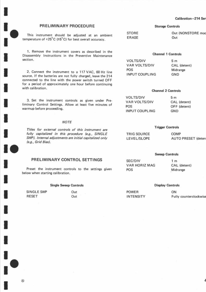
l oPRELIMINARY ONTROL ETTINGS
Preset the instrument controls to the settingsgiven
belowwhen startingcalibration.
SingleSweepGontrols
STOREERASE
Channel
VOLTS/DIVVAR VOLTS/DIVPOSINPUT OUPLING
Cal brati o n-21 4 Ser
StorageControls
Ou t {NONSTOREmodOut
Controls
5 mCAL (detent)
MidrangeGN D
III
II
Channel2 Controls
TriggerControls
TR G SO URCE COMPLEVEL/SLOPE AUTO PRESET deten
SweepGontrols
VOLTS/DIVVAR VOLTS/DIVPOSINPUT OUPLING
SEC/DIVVARHORIZMAGPOS
POWERINTENSITY
5 mCAL (detent)
OFF (detent)
G ND
1 mCAL (detentl
Midrange
IIIII
Display Gontrols
SINGLESWPRESET
Ou tOut
ONFuly counterclockw
!r@ +

5/14/2018 Tektronix 214 Manual - slidepdf.com
http://slidepdf.com/reader/full/tektronix-214-manual 24/95
Calibratio -214 Service
POWER UPPTY ND DISPLAY
Equipment Required
1. RampGenera torTM501/RG 01)4. Probe ip-to-BNCAdapter
2. DC Voltmeter5. 10X BNCAttenuator
3. Low-FrequencyConstant-Ampl i tude ignal Gen-erator General adio1310-8Osc i l la tor ) 6. Three-inch crewdriver
ontrol Settings
Preset instrument ontrols o the settings ivenunderPrelminaryControlSettings.
1. Check Power Supply DC Levels
NOTE
lf the instrument has been operating ntisfactorilyprior to recalibration, proceed with step 2.
a. Using he DC Voltmeter,measurehe DC evel f thepower supplies iven n Table4-2. Observe roper meterpofarity.Se eFig. 4-1 or testpoint locations.
TABLE 4. 2
PowerSupplyAccuracy
b. To measurehe -100 V supply :
1. Depresshe STORE utton.
2. Measurehe -100V supply or a reading f -95vol ts o -110 vol ts(seeFig.4-21.
3. Presshe STOREbutton o releaset.
Supply Measurement-5.6 V -5.6 vol ts10.4vol t
+5.6V +5.6volts10.4 volt
+65 V +6 5 volts t4 volts
-1000v-960 volts140 volts(due o meter oading)
4-4
Fig. 4-1. (A ) Location of Grid Biasadjustmentan d (B ) Power supply est points.
RE V .B,A UG.197

5/14/2018 Tektronix 214 Manual - slidepdf.com
http://slidepdf.com/reader/full/tektronix-214-manual 25/95
I
:oI
ItII
IIl o
Fig. *2. Location of -100 V tost point.
2. AdjustCRT GridBias
a. Connect he DC Voltmeter betweenpin 5 and ptn 2of plug P3 (negativemeter lead to pin 2) on the PowerSupplyBoard A-3).Se eFig.4-1.
b. Turn the INTENSITYcontrol ully clockwise.
Caf brati on-21 4 Serv
b. Position he trace to the centerhorizontalgraticul ine .
c. CHECK-Free-running$/\,eep s parallel with thhorizontal raticule ne .
d. ADJUST-Trace Rotation adjustment, R141 (sFig.4-3) to align the sweepwith the center horizongrat iculeine.
Fig. 4-3. Location of Trace Rotation adjustment.
5. Adiust StorageOperating evel
a. Determinehe upperwriting imit of the CRT.
(1 ) Turn the CH 1 POS control to midrangeanvertically osit ion he two traceswithin the center ougraticule ivisions.
(2 1 Se t th e SEC/DIV switch to 5 m and turn thINTENSITYcontrol ully clockwise.
(3 ) PREsET-Operating eveladjustment, 510 {sF g. 4Al f ul y counterclockwise.
(4 1Connect he DC Voltmeterbetween in 4 of plu22 and ground {negativemeter lead to ground)on thPowerSupply A-3)board.Se eFig.4-4.
(5 ) Depresshe SINGLESW P utton and he STORbutton.
(6 ) Presshe ERASEbutton.
(7 ) Presshe RESET utton.
I
r c. CHECK-Meter eading f +1.9volts.
Id. ADJUST-CRT Grid Bias adiustment,R273, or a
I rneter eading f +1.9volts.
I
e. Disconnectmeter eads.Turn the INTENSITY con-I trol fully counterclockwise.
I
3. AdjustFOCUS
a. Turn the CH 2 PO S ontrol o midra nge nd he CH 1POS ontrol o the OF F detent,
I b. Se t th e SEC/DIV switch to X-Y and adjust the
INTENSITY ontrol or a nominal isplayntens i ty .II
c. ADJUST-FOCUS, 398 (located n the 214 sidepanel ) for a wel ldef ined dot .
- O4. Adjust TraceRotation
I a. Set he SEC/DIVswitch o 1 m.I
4-

5/14/2018 Tektronix 214 Manual - slidepdf.com
http://slidepdf.com/reader/full/tektronix-214-manual 26/95
Cal bration-214 Service
Fig.4-4. Location of storageoperation adjustments.
(8 ) Adjust the LEVEL/SLOPE ontrol or a triggeredsweep.
(9 ) ADJUST-|f the traces hickenor begin o f loodth e CR T during the first minute after Storage, educetheOperat ing evel ,R510, smal l mount lockwise.
(101Repeat teps -a-6 hrough5-a-9 nti l the tracesno longer lood or thickenduring he first minuteafter
Storage.
(11)CHECK-Reading n the DCVoltmeter .Recordthis readingor use n step5-c.
b. Determinehe writing hreshold f the CRT.
(1) Turn the INTENSITYcontro l or the minimumStored race ntensity.
(2) Presshe ERASE utton.
(3 ) Presshe RESETbutton.
(4 ) Adjust the LEVEL/SLOPE ontrol or a triggeredsweep
(5 ) CHECK-For Stored raceswith no breaks n thedisplay uring he irst minuteof storage.
(6 ) ADJUST-|f breaksoccur in the Stored tracesduring th e first minute of Storage,ncreasehe Oper-at ingLevel ,R510, smal l mount ounterc lockwise.
(7 1 Repeat tep 5-b-2 hrough s-b-G ntil no breoccur in the displayduring he first minute of Stora
(8 ) CHECK-Readingon the DC Voltmeter.Recthis readingor use n step5-c.
c. Subtract the voltage eadingof step 5-b€ from t
reading obtained in step 5-a-1 . Add one-half of tdifference o th e reading aken n step5-b-8.Fo r examp
Firs t Reading
SecondReading
Difference
58 volts
28 volts
30 volts
DifferenceSecondRead ing*
T=Opera t ingLeve l
Operating evel or th e example ould be 43 volts.
d. ADJUST-OperatingLevel adjustment,R510, orreading on the DC Voltmeter equal to the voltagecaculated n step5-c.
NOTE
lf the first reading, step d-a-l l, is greater than +55volts, and the second reading, step 5-b-8, is less han+35 volts, adjust R5l0 for a meter reading of +45volts.
e. Removehe meter ea dconnections.
6. AdjustWallBandLevel
a. Connect he DC Voltmeter betweenpin 5 of plug2and ground (positivemeter ead o ground)on the PowSupply A-3)board.SeeFig.44.
b. RotateV", adjus tment, 506 (seeFig.4-41, romfully cllcckwiseo fully counterclockwise.
c. CHECK-For a range f at least 40 V to 0 V whilrotating he V"= adiustment.
d. Press ndhold down the ERASEbutton.
e. ADJUST-V"= adjustment.R506, unt i l the i l luminatedpart of the displaycovers he entireCRT screwith equalbrightness t the centeran dedges f th e scree
4-6 REV,B,AUG. 197
5/14/2018 Tektronix 214 Manual - slidepdf.com
http://slidepdf.com/reader/full/tektronix-214-manual 27/95
I
: oI
IIII
IIl oIItIIt
l o
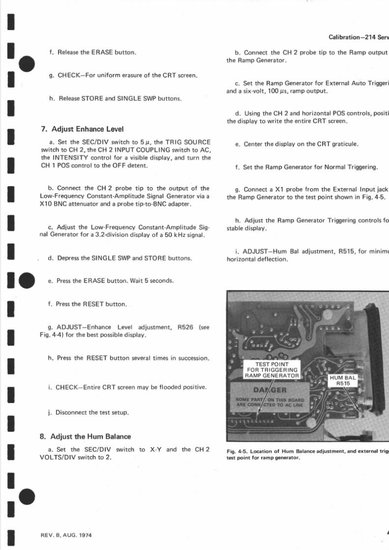
f . Releasehe ERASEbutton.
g. CHECK-For uniformerasure f the CRT screen.
h. Release TOREand SINGLESW Pbuttons.
7. Adjust Enhance evel
a. Set tne SEC/DIVswitch o 5p, the TRIG SOURCEsruitcho CH 2, the CH 2INPUT COUPLING wi tch o AC,the INTENSITY control or a visible isplay,and urn theCH 1 POS ontrol o the OF F detent.
b. Connect the CH 2 probe tip to the output of theLow-FrequencyConstant-Amplitude ignalGenerator ia aXl 0 BN Cattenuator nd a probe ip-to-BNC dapter.
c. Adjust the Low-FrequencyConstant-Amplitude ig-nal Generatoror a 3.2-division isplay f a 50 kH z signal.
d. Depresshe SINGLESWP ndSTOREbuttons.
e. Presshe ERASEbutton.Wait5 seconds.
f. Presshe RESET utto n.
g. ADJUST-Enhance Level adjustment, R526 (seeFig.44 ) fo r th e bestpossible isplay.
h. Press he RESETbutton severalimes n succession.
i. CHECK-EntireCRT screenmay be loodedpositive.
i. Disconnecthe testsetup.
8. Adjust the Hum Balancea. Set th e SEC/DIV switch to X- Y and the CHz
VOLTS/DIV switch o 2.
Gafbration -21 4 Serv
b. Connect he CH 2 probe tip to the Rampoutput the RampGenerator.
c. Set the RampGeneratoror ExternalAuto Triggeran da six-volt, 00 ts , am poutput.
d. Using he CH 2 an dhorizontalPOS ontrols, ositthe display o write he entireCR T screen.
e. Center he display n the CRT graticule.
f . Set he RampGeneratoror NormalTriggering.
g. Connecta Xl probe ro m the External nput ac kth e RampGeneratoro the estpoint shown n Fig.4-5.
h. Adjust the Ramp GeneratorTriggering ontrols orstable isplay.
i . ADJUST-Hum Bal adjustment, 515, or minimhorizontal ef ection.
Fig. 4-5. Location of Hum Balance adjustment, and external triggtest point for ramp generator.
RE V .B ,A UG.1974 4
5/14/2018 Tektronix 214 Manual - slidepdf.com
http://slidepdf.com/reader/full/tektronix-214-manual 28/95
EquipmentRequired
1. DC Voltmeter
2. Low-Frequency Constant-AmplitudeSignalerator General adio1310-BOscillator)
3. Standard mplitudeCalibrator 067-0502-01
4. Square-Waveenerator Type106)
5. Probe ip-to-BNCAdapter
6. GR-to-BNC dapter
7 10X BN CAttenuator
8. 50 {.l BNCTermination
9. Three-inch crewdriver
10. Low-capacitancecrewdriver
Gen-
Galibratio -214 Service
VERTICALSYSTEM
GontrolSettings
Preset nstrument controls to the settingsgiven underPreliminaryControlSettings, xceptas ollows:
INTENSITY VisibleDisplay
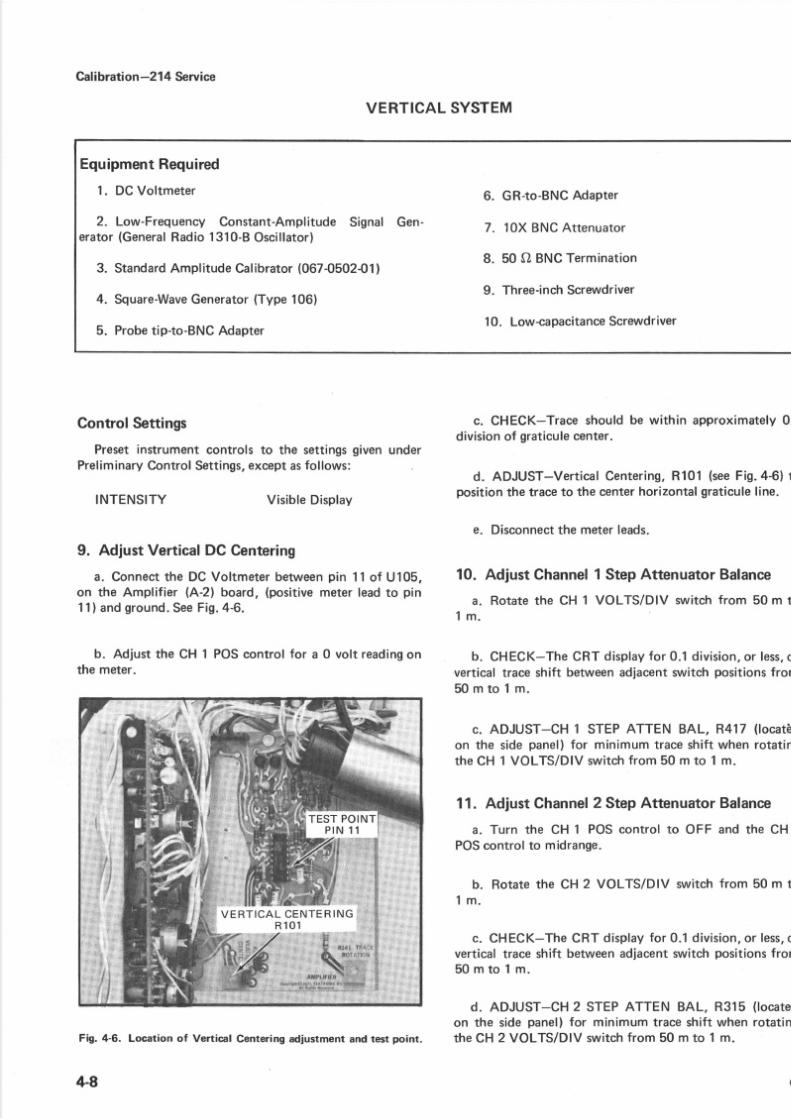
9. AdjustVerticalDCCentering
a. Connect he DC Voltmeterbetween in 11 of U105,on th e Amplifier (A-2) board, (positivemeter ead o pi n11)andground. eeFig.4-6.
b. Adjust the CH 1 POScontrol fo r a 0 volt reading n
the meter.
Fig. 4-6. Location of Vertical Centering adjustment and test point.
4-8
c. CHECK-Traceshouldbe within approximately .division f graticule enter.
d. ADJUST-VerticalCentering,R101 (seeFig.4-61 position he race o the center orizontal raticuleine.
e. Disconnecthe meter eads.
10. Adjust Ghannel StepAttenuatorBalance
a. Rotate the CH 1 VOLTS/DIV switch from 50 m to1 m .
b. CHECK-TheCRT displayor 0.1 d iv is ion, r less,
vertical race shift betweenadjacent witch positions rom5 0 m t o 1 m .
c. ADJUST-CH 1 STEP ATTEN BAL, R417 (locatäon the side panel) or minimum raceshift when rotatinthe CH 1 VOLTS/DIV switch rom 50 m to 1 m.
11. AdjustChannel StepAttenuatorBalance
a. Turn the CH 1 POScontrol to OF F and the CHPOScontrol to midrange.
b. Rotate he CH2 VOLTS/DIV switch ro m 50 m to
1 m .
c. CHECK-The CRT display or 0.1 division, r less,vertical race shift betweenadjacentswitch positions rom5 0 m t o 1 m .
d. ADJUST CH 2 STEPATTEN BAL, R315 (locateon the sidepanel) or minimum raceshift when rotatinth e CH 2 VOLTS/DIVswitch ro m 50 m to 1 m.
@
5/14/2018 Tektronix 214 Manual - slidepdf.com
http://slidepdf.com/reader/full/tektronix-214-manual 29/95
II 12.AdiustVerticalGain
: O cu"ill.i?'.SiÄ,?1TIilY"'#':^I
to 5m and the
b. Connect the CH 2 probe tip to the output of theStandard Amplitude Calibrator via a probe tip-to-BNC
adapter.
c. Set the StandardAmplitude Calibrator or a 20-mVsignal .
d. CHECK-The CRT display for four divisions ofdeflection, ithin 0. 2 division.
e. ADJUST-VERT GAIN, R47O locatedon the sidepanel) or exactly our divisions f deflection.
13. AdjustStorage erticalGain
a. Depresshe SINGLESWP ndSTOREbuttons.
b. Presshe ERASEbutton.
c. Presshe RESETbutton.
d. Adjust the LEVEL/SLOPE control fo r a triggereddisplay.
e. CHECK-CRTdisplay or four divisions f deflection,within 0.2 divisions.
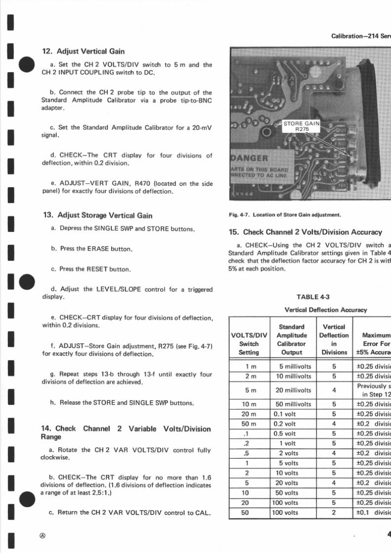
f. ADJUST-Store Gain adjustment,R275 (seeFig. 4-7)for exactly our divisions f deflection.
g. Repeat steps 13-b through 13-f until exactly fourdivisions f deflectionareachieved.
h. Releasehe STOREand SINGLESW P uttons.
14. Check
Rangea. Rotate
clockwise.
Ghannel 2 Variable Volts/Division
th e cH 2 vA R VOLTS/DIV control fui ly
Cafbratio n -21 4 Serv
Fig. 4-7. Location of Store Gain adjustm€nt.
15. CheckChannel Volts/DivisionAccuracy
a. CHECK-Using the CH 2 VOLTS/DIV switch aStandardAmplitude Calibratorsettings iven n Table4check hat the deflection actor accuracyor CH 2 is with5o/ot eachposition.
TABLE4.3
VerticalDeflectionAccuracy
IIIt
IIl oI
IItIII b. CHECK-The CRT display for no more than 1.6
Idivisions f deflection. 1.6divisions f deflecti on ndicates
: O
a ranse f at least .5:1.1
Ic. Return he CH 2 VAR VOLTS/DIV controt o CAL.
VOLTS/DIVSwitchSetting
StandardAmplitudeCalibrator
Output
VerticalDeflectionin
Divisions
MaximumErrorFor
t5% Accura
1 m 5 mil l ivol ts 5 *0.25 divisi
2 m 1 0 ml l iv ol t s 5 10.25divisi
5 m 20 mi l l ivo l ts 4Previously
in Step12
1 0 m 50 millivolts 5 *0.25d vrst
2 0 m 0.1volt 5 10.25d v isi
5 0 m 0.2 volt 4 f]o.z d vtsto
1 0.5 volt 5 10.25d vrsr
.2 1 volt 5 10.25d vtsto
.5 2 volts 4 t0.2 divisi
1 5 volts 5 xO.25 ivisio
2 10volts 5 t0.25 divisi
5 20 volts 4 t:O.2 divisi
1 0 50 volts 5 t0.25 divisi
20 100 volts 5 t0.25 divisi
50 100 volts 2 t0.1 div is i
@ 4

5/14/2018 Tektronix 214 Manual - slidepdf.com
http://slidepdf.com/reader/full/tektronix-214-manual 30/95
Gafbrati o n -21 4 Service
16. Check nput Coupling witches
a. Set hoth INPUT COUPLING switches o DC andboth VOLTS/DIV sruitcheso 10 m.
b. Adjust the Standard Amplitude Calibrator fo r a
20-mVoutput.
c. Position the bottom of the display to the centerhorizontal raticuleine.
d. SetCH 2INPUT COUPLING witch o GND.
e. CHECK-For no verticaldeflection; race is at th ecenterhorizontal raticule ine.
f. Se tCH 2INPUTCOUPLING witch o AC.
g. CHECK-That the display is centered about thecenter orizontal raticuleine.
h. Remove the CH 2 probe tip from the StandardAmplitudeCalibrator.
i. Turn the CH 2 POS ontrol o OFF and he CH 1 POScontrol o midrange.
j. Connect the CH 1 probe ti p to the output of theStandard Amplitude Calibrator via a probe tip-to-BNCadapter.
k. Position the bottom of the display to the centerhorizontal raticule ne.
l . Se tCH 1 INPUTCOUPLING witch o GND.
m. Repeat tep16€.
n. Se tCH 1 INPUTCOUPLING witch o AC.
o, Repeat te p169.
17. CheckCH 1 Volts/DivisionAccuracy ndVari-ableVolts/DivisionRange
a. Set he CH 1 INPUTCOUPLING witch o DC.
+10
b. CHECK-Using the CH 1 VOLTS/DIV switch anStandardAmplitude Calibrator ett ings iven n Table4-3check hat the deflection actor accuracy f CH 1 is withi5o/ot eachposition.
c. Set the StandardAmplitude Calibrator or a 20-m
output.
d. Set he CH 1 VOLTS/DIV srruitcho 5 m.
e. Rotate the CH 1 VAR VOLTS/DIV control fullclockwise.
f. CHECK-The CRT display for no more than 1.divisions f deflection.
g. Return he CH 1 VAR VOLTS/DIV control o CAL
h. Disconnecthe test setup.
b. Connect the CH 1 probe tip to the high amplitudoutput of the Type 106 Square-Wave enerator via
GR-Io-BNC dapter, 50 Sl BNC ermination, ndaprob
tip-to-BNCadapter.
c. Adjust the Square-Waveenerator or a fourdivisiodisplayof a 1'kHzsquare ave.
d. Adjust the Triggering ontrols or a stable isplay.
e. CHECK-The CRT display or flat-top waveformwitno more han +0.2 division, 0. 1 division, r a total of Odivision f aberrations.
NOTE
lf C307, C308, C309, C407, C408, or C409 reguireadjustment, it will be necesffiry to remove theinstrument side panel from the lnput Board (A-l ).Refer to the Dinssembly lnstructions for removalprocedure.
";:l:;:11Til#'"'::,Y":i
@
5/14/2018 Tektronix 214 Manual - slidepdf.com
http://slidepdf.com/reader/full/tektronix-214-manual 31/95
II O
I
tIII
II
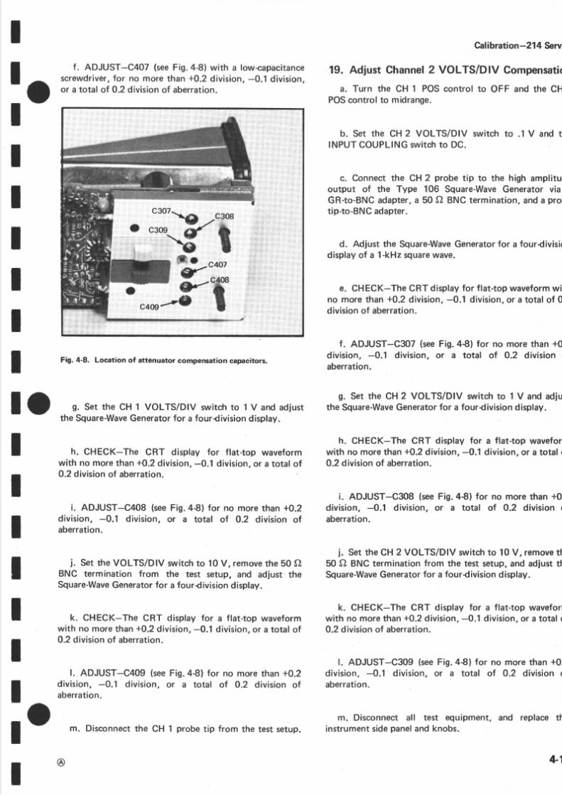
f . ADJUST-C4O7 se eFig.4-8)with a low-capacitancescrewdriver,or no more han +0.2 division, 0. 1 division,or a total of O.2division f aberration.
Fig. 4-8. Location of attenuator compensation capacitors.
h. CHECK-The CR T display for flat-top waveformwith no more han +0.2division, 0. 1 division, r a total of
0.2 division f aberration.
i. ADJUST-C4O8 se eFig.4€) fo r no more han +0.2division, -0.1 division, or a total of O.2 division ofaberration.
i. Set the VOLTS/DlV switch o 10 V, remove he 50 OBNC termination from the test setup, and adjust theSquare-Waveeneratoror a fourdivisiondisplay.
k. CHECK-The CRT display or a flat-top waveform
with no more ha n+0.2
division,0. 1
division, r a total of0.2 division f aberration.
l. ADJUST-C4O9 se eFig.4€l for no more han +0.2divis ion, 0.1 div is ion,or a total of O.2 divis ion ofaberration.
m. Disconnect he CH 1 probe ip from the test setup.
@
Cal bration -21 4 Serv
19. Adjust Channel VOLTS/DIV Compensat
a. Turn the CH 1 POS control to OFF and the CHPOScontrol to midrange.
b. Set the CH 2 VOLTS/DIV switch to .1 V and thINPUTCOUPLING witch o DC.
c. Connect the CH 2 probe tip to the high amplituoutput of the Type 106 Square-Wave eneratorviaGR-to-BNC dapter, 50 O BNC ermination, nda protip-to-BNCadapter.
d. Adjust the Square-Wave eneratoror a fourdivisiodisplay f a 1-kHz quare ave.
e. CHECK-The CRT display or flat-topwaveformwitno more han +0.2 division, 0. 1 division, r a total of 0division f aberration.
f. ADJUST-C3O7 seeFig.4€) fo r no more ha n +0division, -0.1 division, or a total of 0.2 division oaberration.
g. Set the CH 2 VOLTS/DIV switch to 1 V and adjuthe Square-Waveeneratoror a fourdivisiondisplay.
h. CHECK-The CRT display for a flat-top waveforwith no more han+0.2division, 0.1 division, r a total o0.2 division f aberration.
i. ADJUST-C3O8 se eFig.4€) for no more ha n +0division, -0.1 division, or a total of O.2 division oaberration.
i. Set the CH 2 VOLTS/DIV sruitcho 10 V, remove h50 O BNC ermination rom the test setup,and adjust hSquare-Waveeneratoror a fourdivisiondisplay.
k. CHECK-The CRT display or a flat-top waveforwith no more han+0.2division, 0.1 division, r a total o
0.2 division f aberration.
l. ADJUST-C3O9 se eFig.4€) fo r no more han +0division, -0.1 division, or a total of 0.2 division oaberration.
m. Disconnect all test equipment, and replace thinstrument id epanel nd knobs.l o
I O,n,tf.i,1Jffi%:.,:lJ?i?'.",ix,':*,"Jd[i dust
I
IIIIII
+1

5/14/2018 Tektronix 214 Manual - slidepdf.com
http://slidepdf.com/reader/full/tektronix-214-manual 32/95
Cal bration -21 4 Service
20. GheckVerticalAmplifier Bandwidth
a. Set he CH 2 VOLTS/DIV switch o 1 m.
b. Connect the CH 2 probe tip to the output of theLow-FrequencyConstant-Amplitude ignalGenerator ia aXl0 BNCattenuatoranda probe ip-to-BNCadapter.
c. Adjust the SignalGenerator or a sixdivision displayof a 1*Hz s ignal .
d. Without adjusting he output amplitude, ncreaseheoutput frequenryof the SignalGeneratoruntil the displayis reducedn amplitude o 4.2 divisions.
e. CHECK-The Signal Generator output frequencymust be at least100 kHz.
f. Set the VOLTS/DIV srnritcho 2 mV and adiust heSignalGeneratoror a sixdivision isplay f a 1-kHz ignal.
g. Repeat tep20d.
h. CHECK-The Signal Generator output frequencymust be at least200 kHz.
i. Set the VOLTS/DIV switch to 5 m and adjust theSignalGeneratoror a sixdivision isplay f a 1-kHz ignal.
@
i. Repeattep od.
k. CHECK-The Signal Generator output frequencmustbe at least400 kHz.
l.Set
theVOLTS/DIV
switch to 10 m and adjust theSignalGeneratoror a sixdivision isplay f a 1-kHzsigna
m. Repeat tep20d.
n. CHECK-The Signal Generator outöut frequencmust be at least500 kHz.
o. Disconnecthe CH 2 probe ip from the test setup.
p. Connect he CH 1 probe ip to the test setup.
q. Turn the CH 2 POS control to OF F and the CH 1POScontrol to midrange.
r. Set he CH 1 VOLTS/DIV s,rryitcho 1 m.
s. Repeat tep20-c hrough20-n.
+12
5/14/2018 Tektronix 214 Manual - slidepdf.com
http://slidepdf.com/reader/full/tektronix-214-manual 33/95
I
: oI
IIII
II
INTENSITYSEC/DIV
Vis ib leDisplay1 . 0m
O F F
Midrangec H 2
Cafbration -21 4 Serv
TRIGGER IRCUIT
EquipmentRequired
1. Low-Frequency Constant-AmplitudeSignal Gen- 4. BNC-TConnectorerator General adio1310-BOscillator)
5. BNC-to-Bananalu gAdapter2. 42-inch50 A BNCCable6. Three-inch crewdriver
3. Probe ip-to-BNCCable
ControlSettings
Preset nstrumentcontrols o the settings ivenunderPreliminary ontrolSettings xcept s ollows:
e. Return the LEVEL/SLOPEcontrol to the AUTPRESET etent .
f . Set he TRIG SOURCE wi tch o COMP.
g. CHECK-A stable display can be obtained by ajusting the LEVEL/SLOPEcontrol to trigger on both thpositivegoingand negative{oingslopesof the displaywaveform.
h. Se t the TRIG SOURCE switch to EX T and th
of the LEVEL/SLOPE ontrol o the AUTO PRESET etent.
i. Connect he unusedoutput of the BNC-Tconnectto the 214 EXT TRIG input via a 42-tnch 0 O BNCcabanda BNC-to-bananalu gadapter.
j . CHECK-A stable display can be obtainedby ad
justing he LEVEL/SLOPE ontrol to triggeron both thpositive{oingand negativegoing lopesof the displaywaveform.
23. CheckSingleSweepOperation
a. Adjust the LEVEL/SLOPEcontrol fo r a triggerdisplay .
b. Disconnect he CH 2 probe ti p from the signsource.
c. Depresshe SINGLESW P utton.
d. Presshe RESETbutton.
e. CHECK-READY light comes on when RESEbutton is pressed nd remains n until the CH 2 probe ipre-appliedo the signal ource.
CH 1 INPUTCOUPLING DCCH 1 POS
CH 2 PO STR G SOURCE
21. AdjustAUTOPRESET evel
a. Connect the CH 2 probe tip to the output
b. Adiust the Low-FrequencySignal Generator or a0.2div is ion isplay f a 5-kHz ignal .
c. CHECK-Fora s table isplay .
d. ADJUST-AUTO PRESET, R375 (locatedon thesidepanel) or a stable isplay.
22. CheckTriggerCircuit Operation
a. Set he CH2 VOLTS/DlV switch o 1 V.
b. Adjust the Low-Frequency ignalGenerator or a
1div is iondisplay f a 500-kHz ignal .
c. Set he CH 2 VOLTS/DlV switch o 5 V.
d. CHECK-A stable display can be obtained by ad -iusting he LEVEL/SLOPE ontrol to tr iggeron both thepositivegoing nd negative{oing lopesof the displayedwaveform.
RE VB APR1980
r ^ Low-Frequency ignalGenerator GeneralRadio 1310-8
f O ."jr.lff:t)viaa BNc-rconnectornda probeip-to-BNC
I
tIIIIIro
+1

5/14/2018 Tektronix 214 Manual - slidepdf.com
http://slidepdf.com/reader/full/tektronix-214-manual 34/95
Caf brati on -21 4 Service
f . Reconnecthe CH 2 probe ip to the Low-FrequencySignalGenerator.
g. CHECK-READY ight sext inguished.
h. Presshe RESET utton.
i. CHECK-That single-sweepdisplayone weep nlispresented
4-14
5/14/2018 Tektronix 214 Manual - slidepdf.com
http://slidepdf.com/reader/full/tektronix-214-manual 35/95
I
frII
l o
t o
Cal bration -21 4 Serv
HORIZONTAL YSTEM
EquipmentRequired 3. Probeip-to-BNCdapter
1. DCVoltmeter 4. Time-Mark eneratorType 9011
2. Standardmplitude alibrator067O502-01) b. Three-inchcrewdriver
II
It
I
IIIIIt
ControlSettings
Preset nstrument controls to the settingsgiven underPreliminary ontrolSettings xcept s ollows:
25. AdjustHorizontalGain
a. Connect the CH 1 probe tip to the output of tStandard Amplitude Calibrator vi a a probe tip-to-Badapter.
b. Adjust the Standard Amplitude Calibrator fo r20 mV output signal.
c. Se t he CH 1 INPUTCOUPLING witch o DC.
d. CHECK-The CRT display for two dots separahorizontally y four divisions,0.2 division.
e. ADJUST-HORIZ GAIN, R475 (located n the sipanel) or four divisions f deflectionbetween he dots.
f. Disconnect he CH 1 probe rom the StandardAmp
tude Calibrator.
INTENSITYSEC/DIVCH 2 POS
Visible isplayX-YMidrange
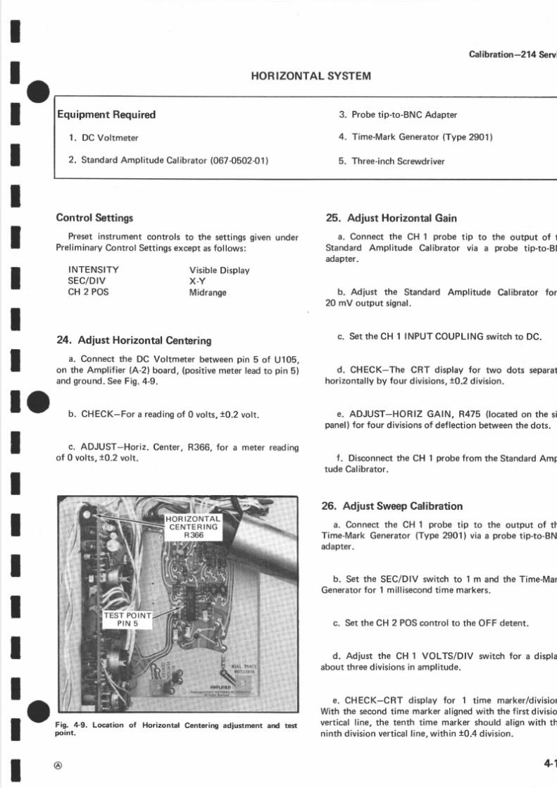
24. Adjust HorizontalCentering
a. Connect he DC Voltmeter between in 5 of U108,on the Amplifier (A-2)board, positivemeter ead o pin 5)an dground.Se eFig.4-9.
b. CHECK-Fora reading f 0 vol ts ,10.2 ol t .
c. ADJUST-Horiz. Center,R366, or a meterreadingof 0 vol ts ,10.2 ol t .
Fig. lt-9. Location of Horizontal Centering adjustment ard testpoint.
@
26. AdjustSweepCalibration
a. Connect the CH 1 probe tipTime-MarkGenerator Type2901)adapter.
to the output of thvi a a probe ip-to-BN
b. Set the SEC/DIV switch o 1 m and the Time-MaGeneratoror 1 millisecondime markers.
c. Set he CH 2 POScontrol to the OFF detent.
d. Adjust the CH 1 VOLTS/DIV switch or a displaabout hreedivisionsn amplitude.
e. CHECK-CRT display fo r 1 time marker/divisiWith the seco nd ime markeralignedwith th e first divisiovertical ine, he tenth time markershouldalignwith thninth division ertical ine,within t0.4 division.
4-1

5/14/2018 Tektronix 214 Manual - slidepdf.com
http://slidepdf.com/reader/full/tektronix-214-manual 36/95
Cal bration -21 4 Servi e
f. ADJUST-SWP CAL, R370 (located on the sidepanel) or exactly eight divisionsof deflectionbetween hesecond nd enth time markers.
27. CheckVariableHorizontalMagnifierRange
a. Rotate he VAR HORIZ MA G control ful ly clock-wise.
b. CHECK-The CRT display or at least iv e divisionsbetweenadjacent ime markers. ivedivision pacingndi-cates VAR HORIZ MAG control ange f at least :1.
c. Return he VAR HORIZ MAG con trol to th e CAdetent.
28. CheckSEC/DIVAccuracy
a. CHECK-Apply th e appropriate ime markersancheck each position of the SEC/DIV switch for proptiming over the centereightdivisionportion of eachsweewith in 0.4div is ion.
@-16

5/14/2018 Tektronix 214 Manual - slidepdf.com
http://slidepdf.com/reader/full/tektronix-214-manual 37/95
I
: ot
tIII
It
Component Color Coding
The resistorsused in the 214 are either compositionresistors r precision esistors. he resistancealuesar ecolor-coded n the components ith EtA color-codesomeprecision esistors ay have he value rintedon the body).The color-code s read startingwith the stripe nearestheend of the resistor.Composition esistors ave our stripeswhich consist f two significantigures, multiplier, ndatolerance alue (seeFig.5-2). Precisionesistors ave ivestripes onsisting f three significant igures,a multiplier,an da tolerance alue.
The capacitance values of common disc capacitors andsmall tubular electrolyticsare marked in microfaradson theside of the component body. The molded electrolyticcapacitors are color-coded in picofarads (seeFig. 5-2).
Th e cathode end of each glass-encasediode is ndicatedby a stripe, a seriesof stripes, or a dot.
@
Section 5-214 Serv
Troubleshooting qupmentThe majorityof troubleshootingo be done on the 21
can be accomplished ith a 20,000ohms/voltVOM sucha Triplett Model 230-NA or a SimpsonModel 262. Usedynamic semiconductor ester,such as a Tektronix Typ577 Curve Tracer System, o check the semiconductused n the 214. To check waveforms n this instrumeusea test oscilloscope ith at leasta DC to 500 kiloherfrequency response nd one millivolt to 50 volts/divisdeflection actor.
A2A M P L I F I E R
BOARD
I Ocomponentocators.
IIIIIII
5-
T R O U B L E S H O O T I N GI D S
DiagramsnformationComplete ircuitdiagrams regiven n the foldoutpages
in the Diagrams ection. he circuit numberand electricalvalueof each component n this instrumentare shownonthe diagrams se e irst pageof th e Diagrams ection ordefinition of the referencedesignators sed to identifycomponentsn this instrument).mportantwaveforms realso shown on th e diagram.Th e portions of th e circuitmounted n circuitboards reenclosed ith blue ines.
Fig.5- 1 shows he locationof the circuit boardswithinthe instrument, longwith theirassemblya)numbers. heassembly umbersare also usedon th e diagramso aid inlocating he boards.Component ocators re shown n theDiagrams ection,on the back of the pageopposite hecircuit diagram, o aid in cross-referencingetween hediagrams nd the circuit boards. ac helectrical omponenton the boards s identif iedby its circuit numberon the
l o Fig.5-1. Location of circuit boards within the 214.

5/14/2018 Tektronix 214 Manual - slidepdf.com
http://slidepdf.com/reader/full/tektronix-214-manual 38/95
Troubleshooti g Aids-2 14 Service
Fig. 5-2. Color code for resistors, ceramic capacitors, and dipped tantalum electrolytic capacitors.
Resa3tor and Capacitor Color Cod e
Ceramic
Capacitors:
Oapped Tantalum
Electrolyticr: rFor capacitance of 10 pF or loss.
' iFordipped tantalum capacitors only,
+Led Lead
O@ "nO @-lst,2nd, and 3rd significant igures:
@-multiptl*,
O-tol€rance:
@-a"-o"r"ture coeff cient;
@-eotaritv and Yoltage ating.
rrrOTE: @ ana/or @ color code or capacitors epends ponmanufacturorand capacitor ype. May not bs pressnt n somecages.
5-2

5/14/2018 Tektronix 214 Manual - slidepdf.com
http://slidepdf.com/reader/full/tektronix-214-manual 39/95
I
frtI
I
!.
Section6-214 Serv
C I R C U I T E S C R I P T I O N
Th e following circuit descriptionbeginswith a dis-
I cussion f the instrument sing he block diagram ocatedI in the Diagram ection t the rearof this manual. heneach
circuit s describedn detail,usingdetailed iagrams here
I necessaryo show the interconnections etween he stages
I in eachmajor circuit and the relationship f the externalr controls o the individual tages.n addit ion o the block
diagram,complete schematics re given n th e Diagram
I section.I
BLOCKDIAGRAMDESCRPTIONI
Signals o be displayed n th e CRT are applied o the
I o ili;:g;:::itl{#li:#rulrkT+":fillmplifiers.The Input Amplifier circuits also contain he
I verticaldeflection,position (with channel n-OFF), nputI coupling, ariable ttenuation, ndbalance ontrols.
I
I Th e TriggerGenerator ircuit initiates he sweep ignalr produced y th e SweepGenerator. he input signal o th e
TriggerGenerator anbe selectednternallyeither rom the
I capacitively oupledCH 1 Inpu t Amplifier signal, r from
I the directly coupledCOMPsignal f the Feedback mpli-- fier. The TriggerGeneratornput signal analsobeselected
from the external ignal pplied o the EXT TRIG banana
Ijack. Th e TriggerGenerator ircuit contains ouplingan d
I sourcecontrols n addition to a combination evel/slopecontrol.
The SweepGenerator ircuit produces linearsawtooth
output signal when initiated by the Trigger Generatorcircuit, The slopeof the sawtoothproducedby the SweepGenerator ircuit scontrolled y the SEC/DlVswitch.Th eoperating mode of the SweepGeneratorcircuit is deter-mined by th e Trigger LEVEL/SLOPEcontrol and th eSINGLE SWPpushbut ton.n the AUTO PRESET etent ,the absence f an adequate riggersignalcauseshe sweepto free run. When he LEVEL/SLOPE ontrol sout of theAUTO PRESETdetent, a horizontal sweep s presentedonly when correctly riggered y an adequateriggersignal.
REV. ,APR. 977
Th e SingleSweepmodeof operation llowson e (andoone) ffiggeredsweep o be initiatedafter he circuit is rewith the RESET button. The Sweep Generator aproducesan unblankinggate signalcoincidentwith tsawtoothwaveform.This gateslgnal nblanks he CRTpermitdisplaypresentation.
The output of the SweepGenerator ircuit is amplifby the HorizontalAmplifier circuit o produce he corrhorizontaldeflection or th e CR T fo r al l positions f tSEC/DIV switch. Th e Horizontal Amplifier containvariablemagnifier o increasehe sweep ateup to at leamaximum of five times n an y positionof the SEC/Dswitch.
The CRT circuit contains he controls necessaryoperationof the cathode-rayube. Trace storage s accoplished y the Storage ircuit.The PowerSupplyand CRcircuitsprovideall the voltages ecessaryor operation
this nstrument.
CIRCUITOPERATION
In the followingdescription f the electrical peratan d relationshipof the circuits in the 214, circuicommonly usedby Tektronix s only br ief ly explainedmore nformation sdesired n the commonlyused ircurefer o the following extbooks:
Phillip Cutler, "Semiconductor Circuit Analys
McGraw-Hi l l ,ewYork, 1964.
Lloyd P. Hunter (Ed.), "Handbook of SemiconducElectronics", second edit ion, McGraw-Hill,New Yor1962.
Jacob Millman and HerbertTaub, "Pulse,Digital,aSwitchingWaveforms", cGraw-Hill, ewYork, 1965.
I
6
5/14/2018 Tektronix 214 Manual - slidepdf.com
http://slidepdf.com/reader/full/tektronix-214-manual 40/95
'n|Cl
oi
o
o!t==Ec
o3g
6'ogo
E,Egoo-CL
,E'o3
oI I tI oI II r I r I r I r I r I
FROM E RTMODEMULTI
FE E DB A CKA M P L I FE R
N O . 1
c H l
@lTO
TRIGCIRCR441
R440
EI
F R O M C H 2P R O B ET I P
STEPATTEN BA
TOVERT iMODE o;o cM U L T I CH 1 O F F
C H 2 O F F7,dBJfiüIr,g-4
II
ca27T
ID c i)
G N D r 2
cR343 CR342
TOT R I G G E RC I R C U I T
FROMV E RTMODEMUL TI
c4ol lt"-)\U* |-@
tleü-.r: EroouP R O B ET I P
INP UTSOURCE
FOLLOWERo414A
ATTENUATORSTAGE
FE E DB A CKA M P L I F I E R
N O . 2EEDBACKS OURCE
FOLLOWER
04148
FE E DB A CKS OURCE
FOLLOWER
o3148FE E DB A CKA M P L I F I E R
FE E DB A CKA MP L IF IE R
N O . 2INP UT
S OURCEFOLLOWER
o314A
ATTENUATORSTAGE

5/14/2018 Tektronix 214 Manual - slidepdf.com
http://slidepdf.com/reader/full/tektronix-214-manual 41/95
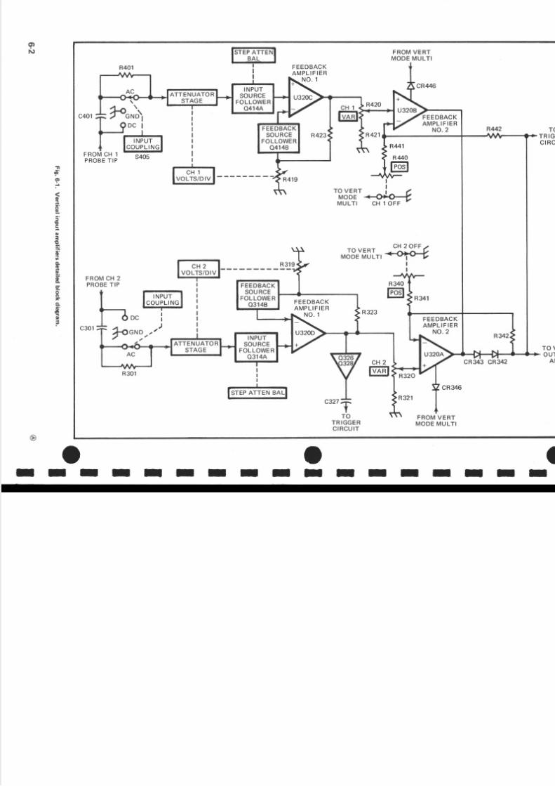
II VerticalnputAmptifiersO-
O Input signalsor verticaldeflectionof the CRT of theI
- 214 are applied o the tips of the attachedprobes.Each
I Tt-1, Totitilr.?ro.uig.,:ontrol f nput.couplins,.varia.ble
the
Input Amplifierprovides ontrolof input coupling, ariableattenuation. ertical ef ection actor,balance, ndverticalposition (with channel on-OFF) fo r th e appropriatechannel .F ig.6-1 showsa detai ledblock diagramof theVertical nput Amplifier circuit.A schematic f thiscircuitis shownon diagram .
output signalsro mamplification n the
Circut Descriptio -21 4 Serv
the Paraphasemplifiers eceiveincommon baseOutput Amplifier stag
IIII
II
I
IIII
I O
I
f.
Input signalsapplied to th e tips of the probes areconnected o the appropriateAttenuation Stage hroughth e INPUT COUPLINGswitches 5305 an d 5405). Thedeflection actor in each channel s determinedby theVOLTS/DlV switch (S310or 5410). In all positions f theVOLTS/DlV switches elow .1 V/DIV, the correctdeflec-t ion factor is achieved y changinghe gain of FeedbackAmplifiers U320-D an d U320-C. In sryitch positions.1 V/DlV and up, precision attenuators ar e used (i naddit ion o changinghe gain of U320-Dand U320-C) o
achieve the correct deflection factors. When the VARVOLTS/DlV control is rotated, he signal s attenuatedacrossR320 and R420.This offersvariable uncalibrated)deflection factors between the calibratedsettingsof theVOLTS/DIV switch.Th e STEPATTEN BAL adjustments(R315 and R4 17) control the traceshift when switchingbetween ef ection actors.
The 214 ca n be operated ingle raceby turningeitherverticalPO Scontrol to the OF F detent; hi s disableshatchannel n the last eedback tage f the Input Amplifierthrough he operationof the VerticalMode MultivibratorU440. The CH 2 triggersignal s present egardlessf the
CH 2 POS control setting. In the dual-tracemode, th einstrumentwill automatically ho p or alternat e, ependingupon he sweep ate.
VerticalandHorizontalOutputAmplifie* €>
Th e Vertical and HorizontalOutput Amplifiersprovideth e final amplification or th e deflectionsignals. ig.6- 2showsa detailedblockdiagram f theseOutput Amplifiers.A schematic f these ircuits son diagram .
Both amplifierscontain the samebasiccircuitry.Th esingle-endednput signals re applied o paraphasempli-fiers, U105-A and U105-8, to convert the signal ntopush-pull utput signals. he VerticalParaphasemplifierstagecontains he VERT GAIN adiustment R470) ha tsets he overallgainof the verticalsystem, nd a VerticalCenteringadiustment (R101) to set DC centering.Th eHorizontalParaphasemplifier stage ontains he HORIZGAIN adjustment R475) , he VAR HORIZ MAG control(R476). and th e Horizontal POS control (R480). Th e
@
TriggerGenerato,O
Integrated ircuit U370 is a combinationTrigger/Sw
Generator. The Trigger portion derives trigger signinternally, either from th e capacitivelycoupled CHVertical Input Amplifier, or from the d irectly coupCOMP signal from the input of the Vertical OutpAmplifier. The TriggerGenerator an also selectsignfrom an externalsignalapplied o the EXT TRIG inpbanana ack. Controls re provided n this circuit o seltrigger evel,slope,and source.Fig.6-3 showsa detaiblock diagramof the Trigger/SweepGenerator ircuitsschematic f this circuit s on diagram .
SweepGeneratorO
Th e SweepGenerator ortion of U370serves multippurpose. n al l positionsof the SEC/DIV switch,exceX-Y, the SweepGenerator san integrator,which generaa linearsawtoothvoltagewaveform.This output signaproducedon command (triggerpulse) ro m the TrigGeneratorcircuit. The slope of the sawtooth voltagecontrolled y the setting f th e SEC/DlV (53601 witch.
Th e SweepGenerator lsoproduces n unblanking asignalcoincidentwith the sawtoothwaveform.This gas ignal s ampl i f iedby Unblank ingAmpl i f ier 0134 aapplied to the CRT to unblank he CRT during swepresentation.n addi tion, he SweepGenerator uppliesclock pulseso the VerticalModeMultivibrator U440)alternate witchingbetween hannels.n the X- Y positof the SEC/DIV switch, the SweepGeneratorbecomefeedbackamplifier to amplify the signalapplied o tCH 1 probe ip. Fig.6-3 showsa detailed lockdiagramthe Trigger/SweepGeneratorcircuits. A schematic f thcircuit son diagram .
Sinsle weepO
In the SingleSweepmodeof o peration, he Auto Triggis disabled nd sweep nitiation s controlledby the Sin
Sweep Reset circuit. Also, Sweep Start Holdoff is cotrolled by latch circuit 0532 and 0535 instead of thSweepGenerator.A schematic f the SingleSweepcircis on diagram .
The SweepStart Holdoff waveform(seeFig. 6-4) frothe SweepGenerators applied o the Single weep ircuThe positivegoingstep of thi s waveform {SweepStartlcoupled hrough C530 to turn on 0530. When0530 tur
6
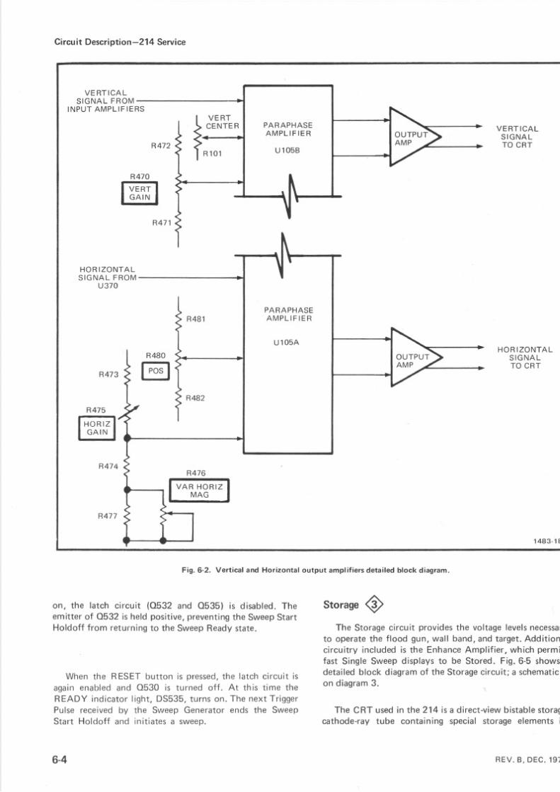
5/14/2018 Tektronix 214 Manual - slidepdf.com
http://slidepdf.com/reader/full/tektronix-214-manual 42/95
Ci cu t Descriptio -214 Service
PARAPHASEA M P L F E R
U 1 O 5 B
V E R T I C A LS I G N A L F R O M
INP UT " ' ' ' ' " J
HOR ZONTALS I G N A L R O M
u370
R475r-lI n ( J r i rz _ II r ' l ^ l l \ l I
le ^ r r v
I
R474
R476
l* i l ff"I
V E R TCE NT E
R1 0 1
V E R T I C A LS I G N A LTO CRT
HOR ZONTALS I G N A LT O CRT
1 4 8 3 - 1 8
R480
tril
PARAPHASEA M P L F E R
U 1 O 5 A
Fig. 6-2. Vert ical and Horizontal output ampli f iersdetai led block diagram.
storaseQn, the latch c ircui t (0532 and 0535) is disabled. heemitterof 0532 i s heldpositive, reventinghe SweepStart
Holdoff ro m returning o the SweepReady tate.
When the RESET but ton i s pressed,he la tch c i rcu i t is
aga in enabled and 0530 is turned o f f . At th is t ime the
READY ind icator ight , DS535, turns on. The next T r iggerPulse received by the SvueepGenerator ends the SweepStar t Holdof f and in i t ia tes a sweep.
6-4
Th e Storage ircuit provideshe voltage evels ecessto operate he flood gun,wall band,and arget.Additionc ircui t ry nc ludeds the Enhance mpl i f ier ,whichpermfast S ingleSweep isplays o be Stored.Fig.6-5showdetailed lock diagram f the Storage ircuit;a schemation diagram .
The CRT used n the214 sa direct-v iewis table toracathode-ray ube containingspecialstorageelements
R E V . B , D E C . 1 9 7

5/14/2018 Tektronix 214 Manual - slidepdf.com
http://slidepdf.com/reader/full/tektronix-214-manual 43/95
I-oI
IIII
tIl oIIIIIIIl o
@
Ci cu t Descri tion-214 Serv
tf""y+-i-o ',, HORIZONTAS IGNA L O
HORIZ ONTA M P L I F I E
U N B L A N K I N GAMP
UNB LA NK l NS I G N A LTO CR T
CLOCKPULSTO VERTICAMODEMULT
F R O M S I N G L ES W E E PC I R C U I T
{ 2 . N L Y I
Jl< oco'tP
H2 ONLY
R375
@
Fig. 6-3. Trigger/Sweep Generator detailed block diagram.
6-
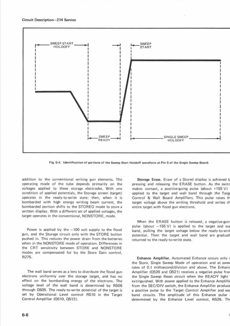
5/14/2018 Tektronix 214 Manual - slidepdf.com
http://slidepdf.com/reader/full/tektronix-214-manual 44/95
Circut Descriptio -214 Service
F_sTffi"'Jf'-l
S I N G L ES W E E PHOLDOFF _
Fig. 6-4. ldentification of portions of the Sweep Start Holdoff waveform at Pin 5 of the Single Sweep Board.
addit ion to the conventionalwriting gu n elements. heoperatingmode of the tube dependsprimarily on th evoltagesapplied to these storageelectrodes.With one
conditionof appliedpotentials.he Storage creen target)operates in the ready-to-writestate; then, when it isbombardedwith high energywriting beam current, hebombarded ortion shifts o the STOREDmode o storeawritten display.With a different se tof appliedvoltages,hetargetoperatesn the conventional, ONSTORE,mode.
Power s appliedby th e -100 volt supply o th e floodgun, and th e Storage ircuit only with the STOREbuttonpushed n. This reduceshe powerdrain ro m th e batterieswhen n th e NONSTOREmodeof operation.Differencesnth e CR T sensitivitybetweenSTORE and NONSTOREmodes are compensatedor by th e Store Gain control,R275.
The wall bandservessa lens o distribute he floodgunelectronsuniformly over the storage arget. and has noeffect on the bombarding energyof the electrons.Thevoltage evel of the wall band is determinedby R506through 0505. The ready-to-write otentialof the target sset by Operational Level control R510 in the TargetControlAmpl i f ier O510, 512) .
6-6
StorageErase.Eraseof a Storeddisplay s achieved pressing nd releasinghe ERASEbutton. As th e switcmakes contact, a positive€oingpulse (about +155V) i
applied o the target and wall band through the TargControl & Wall Board Amplifiers.This pulse raises htarget voltageabove he writing thresholdand writes thentire argetwith f loodgu nelectrons.
When the ERASE button i s released, negativegoipulse (about-155V) is appl ied o the target and waband, pull ing the target voltagebelow the rea dy-to-wrpotential. Then the target and wall band ar e graduareturned o the ready-to-write tate.
EnhanceAmplifier. Automated Enhance ccursonly inthe Store, SingleSweepMode of operation and at sweeratesof 0.1 millisecond/divisionnd above.The EnhanAmplifier (0520 and 0521) receives negative ulse ro mth e SingleSweepReset ircuit when the READY light iextinguished. it h powerapplied o the Enhance mplif iefrom th e SEC/DlVswitch, he Enhance mplif ierproduca positivepulse o th e TargetControl Amplifier and waband circuits. The amplitude of this Enhancepulse ideterminedby the EnhanceLevel control, R526. Thi
@
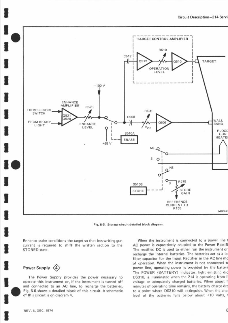
5/14/2018 Tektronix 214 Manual - slidepdf.com
http://slidepdf.com/reader/full/tektronix-214-manual 45/95
I
: oI
IIII
IIl oIIIIII
-oI
Fig. 6-5. Storagecircuit detailed block diagram.
Enhance ulseconditions he target o hat less ritingguncurrent is required o shift the written section o theSTORED tate.
Power upplyOTh e Power Supply provides th e power necessary o
operate this instrument or , if the instrument is turned offand connected to an AC l ine, to recharge he batteries.Fig. 6-6 shows a detai led block of this circuit. A schematicof t his c i rcui t is on diagram4.
REV.B , DE C. 974
When th e instrument is connected to a power l ine th
AC power is capacit ively coupled to the Power Rectif i
Th e recti f ied DC is used to either run the instrument or
recharge he internal batteries. The batteries act as a lar
fi l ter capacitor for the lnput Rectif ier in the AC line moof operation. When th e instrument is not con nected topower l ine. operating power is provided by the batteri
The P OWE R (B A T T E RY ) i nd i ca to r , i gh t emi t t i ng d i o
DS 310 , s i l l um i na tedwhen the 214 i s ope ra t i ng rom l i
vo l tage or adequate lychargedbat ter ies .When about f i
minutesof operat ing ime remains , he bat tery charge ro
to a poin t where DS310 wi l l ex t ingu ish.When the cha
level of the bat ter ies fa l l s be low about +10 vol ts, t
Circu t Descri tio n -21 4 Servi
!- i"-* ät t äolJ *-o o-r,n-t,t*- I
OP E RA T IONL E V E
F R O MS E C / D I VSWITCH
F R O M R E A D YL I G H T
WA LLBAND
FLOODG U N
HEATETL5 l OA--@
+65 V
jP-'55 l OB b-l nzzs".fto^,
I G A I NTR E F E R E N C E
C U R R E N T OR1 5 5
1483-20
E N H A N C EA M P L I F I E R
E N H A N C E
L E V E L
6

5/14/2018 Tektronix 214 Manual - slidepdf.com
http://slidepdf.com/reader/full/tektronix-214-manual 46/95
Circu t Descri tio n -21 4 Servi e
u J ,
E3=E ( )
o o t r* b.-,
r LE r( )6o EF O
oo
I
q e är o q r ö+ t +
Fut =,z o -= z
1483-21
(rt u L F N c " ) \ t t o or . l f r o r n l o l o | ' o r o- . \ ( \ l N $ l ( \ l C ! N
t n t r r r t r r r t r t rQ = ( ) ( ) O ( J ( ) Our c){E
ü ü $< t ! o
ö E Iä H ü
IIII
,ff|l ( r I
- I a I
; Ä t v t
.l:l
cE o,IJJ +F - ( \
a t o
2 = $oO0 O e( 9 tC \ N( E E> O
. ^ oE{ st11 c.l; ' i cc- ( )
o
CEoCEccuJ
6 sE 8
f
!c
rJJ F-l-- c"l
P 8CL
Etl l .o (oFl l . F F F
- c \ N o lt: (rFI--H < - l o oTE
td : [ r olll UJ e
< F C ' )^ j - u )t s k o
dl
t;Ifrlr#
t __ _ _
( r pLu !
= do zo - -
6-8
Fig. 6-6. Power Supply circuit detailed block diagram.
REV. B , D E C . 1 9 7

5/14/2018 Tektronix 214 Manual - slidepdf.com
http://slidepdf.com/reader/full/tektronix-214-manual 47/95
I
:oI
IIII
II
IIIIIIII
Fig. 6-7. CRT Circuit detailed block diagram.
(CRT). F ig. 6-7 shows a deta i ledb lock d iagramof the CRci rcu i t . A schemat ic f th is c i rcu i t i s on d iagram3.
NOTE
See he Storage Circuit description for operation of
the CRT in the STOREmode.
Rectif iers CR261 through CR268 provide th e negati
accelerating potential fo r th e CRT. Voltage output
approx imate ly -1000 vo l ts a t the CRT cathode. F i lame
voltage for the CRT is provided by a separatewinding o
T25O. Display intensity an d focus are control led by R39
and R294 respectively. Th e Trace Rotation adjustme
controls th e current through L300 and affects both th
ver t i ca land hor izonta la l ignmentof the CRT beam.
Circu Descri tio n -21 4 Serv
R 1 4 1TRACE
ROTATION
R E F E R N C EC U R R E N TT O U 1 0 5
FOCUSR394
FROMPOWERSUPPLYC I R C U I T
U N B L A N K I N GS I G N A L F B O M
o134
1 4 8 3 - 1 9
H G HVOLTAGESUPPLY
l o
DischargeProtect ion c i rcu i t (O231 and 0235) prevents heConverter Multivibrator (0242 an d 0249l ' from func-t ion ing. The Conver terMul t i v ibra tor changesDC into AC,which is app l ied acrossT25O and then rec t i f i ed in to theappropriate DC voltages n the Rect if ier circuit. 4242 an d4249, togetherwi th VR238, also act as a Regula tor n thePr imary of T250. Error Amp 0235, VR238, CR240, andCR241 cont ro ls the vo l tage changes to the Conver terMul t i v ibra tor .
Power is applied to T280 to activate the -100 voltsupp l ies , nd the f lood gun of the CRT only in the STOREmode of operation. This reduces he power drain from th ebat ter ieswhen operat ing n the NONSTORE mode.
.- . CRTCircuitg
V Th e CRT circuit provides he high voltage nd controlcircuits necessaryor operationof the cathode-rayube
REV, B , D E C . 1 9 7 4

5/14/2018 Tektronix 214 Manual - slidepdf.com
http://slidepdf.com/reader/full/tektronix-214-manual 48/95
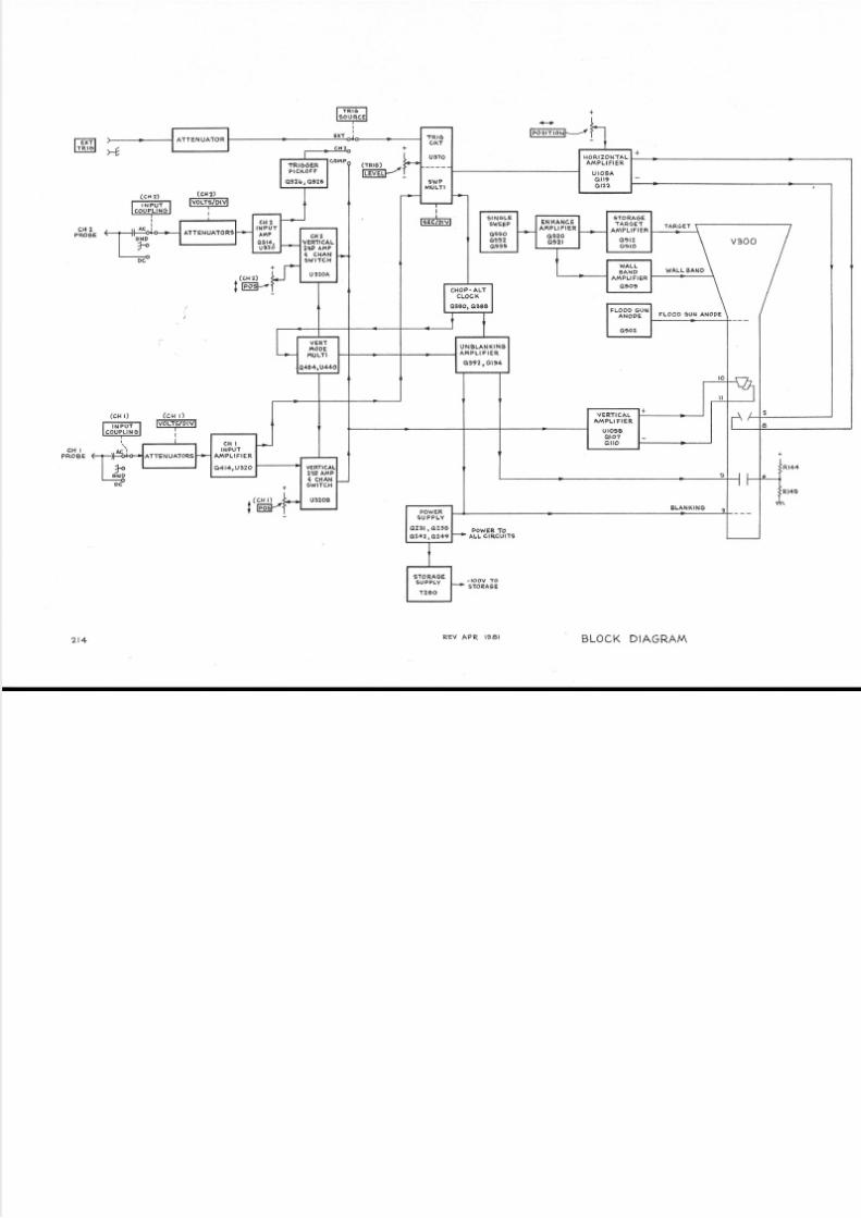
5/14/2018 Tektronix 214 Manual - slidepdf.com
http://slidepdf.com/reader/full/tektronix-214-manual 49/95
lffi;lI
>4
c A 2PROBE
(cH t)
tml(c H t)
lvoLTs/DlVl
c H lP R OB E
POWER OALL CIRCUITS
-toov ToSAORA6E
ATTENUATOR
HORIZONTALAM PL I FI ER
U OSAol l9ol22
IRI66ERP C KOF F
ae26, oazs
FLOOD 6U[ AN O9 E
c H 2I N P U T
o 3 l 4 rua?o
ENHANCEAr {PLIF IER
o520092 l
HzVERTICAI2{9 AAp€ CHANSW l l c H
U32OA BANDAMPLI FIER
o50'CItOP. ALT
CLOCK
oaaot o36a
UNBLANKIN6AlilPLl F ER
a3t2,ota4
POWER9UPP Y
a?i,t , a7)6a242, O249
(cH ) -19!.31-
tffit *ry
2 t 4 R,EVAP R I98I BLOCK DIAGRA/V\

5/14/2018 Tektronix 214 Manual - slidepdf.com
http://slidepdf.com/reader/full/tektronix-214-manual 50/95
z;oD;
3
E
5
a
-
o
E
g
!
t
rsEE:onEU
$

5/14/2018 Tektronix 214 Manual - slidepdf.com
http://slidepdf.com/reader/full/tektronix-214-manual 51/95
21
VOLTAGES ND WAVEFORMS
The voltages nd waveforms hownon this diagramwereobtained by using the fol lowing test set-ups and testequipment.
VoltageMeasurements:
Set he front and sidepanelcontrols o mid-range.
Input couplingswitches o ground (GND). Trace posi-tioned o the centerhorizontal ine.
Voltmeter common is connected to the instrumentcommon.
WaveformMeasurements:
The 214 Oscilloscope nder test: Th e frontpanel controls are set to mid-range. he inputswitches re set to AC. The verticaldeflection sswith a two millivolt sguarewaveconnectedo CHtwo millivolt sinewaveconnectedo CH 2. Th e Sswitch s set or 0.5 m with a trjggered isplay.
Test Oscilloscope: he test oscilloscopes itriggered; he vertical deflection and horizontal tindicatedon the waveform photo. The vertical npcoupled. The tolerance of the voltagesand wave2Oo/". he test oscilloscopeused or the wave ormTektronix7503with a readout isplay.
RECOMMENDED EST EOUIPMENT
ITEM SPECIFICATIONS RECOMMENDEDYPE
Oscilloscope Frequency response 00 k iloher tz . Tek t ron ix2'11 r equivalent.
Voltmeternonloading gitalmultimeter
lnput impedance: 0 MSI
Range :0 - l kV
Tektronix7D13 Digitalmultimtest oscilloscopewith readorequired.
FairchildModel7050or equiv

5/14/2018 Tektronix 214 Manual - slidepdf.com
http://slidepdf.com/reader/full/tektronix-214-manual 52/95
.X , rPtö
z
sH
-
ö s
;
-
9
I
3
ts1
1
-4
d
ö
t3
tE
g
F
r
s
ä
8
3
ro
'>
,z2g
J
: s
; tiF
!*g
üi
5 3:F
bi6
0
ePt>
r E
'*$
e-d%
_Fb
$
f F 3 i P
^E!n
o.
+
e g z F ß
Ie rFf_ g
A
l
o!
f3"s rSg \
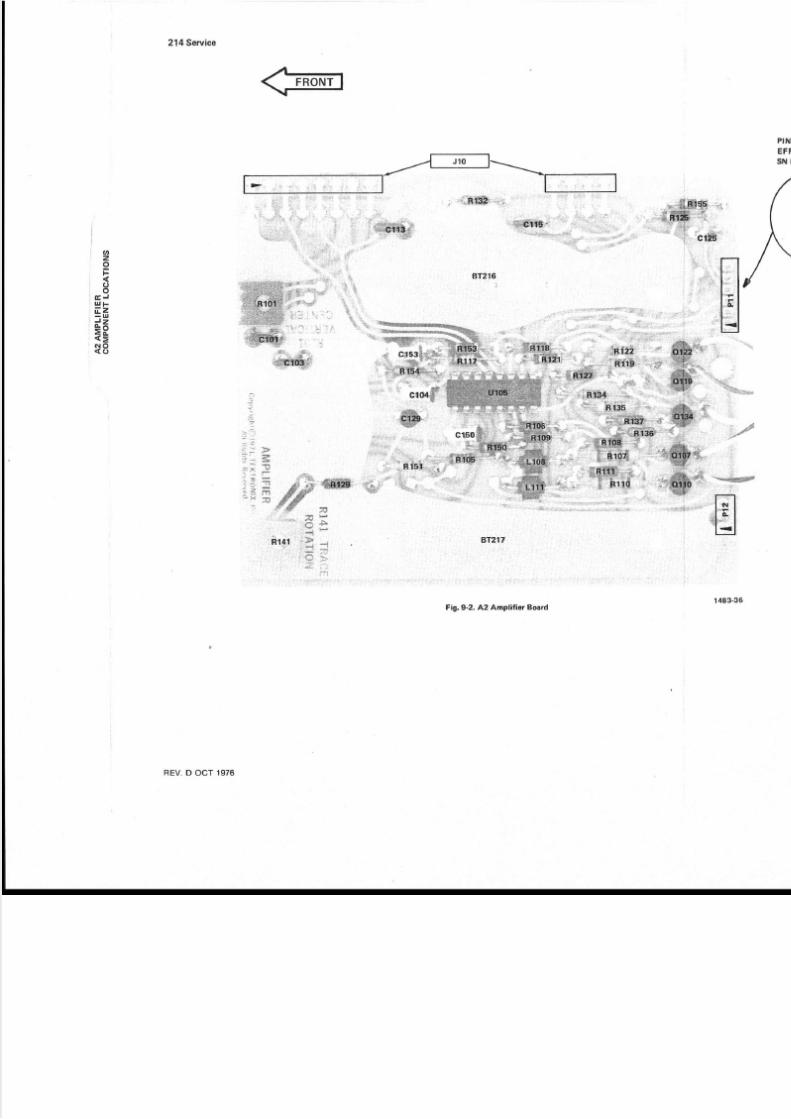
5/14/2018 Tektronix 214 Manual - slidepdf.com
http://slidepdf.com/reader/full/tektronix-214-manual 53/95
=H;
i
1
y
9
1
IXrRo
x
^hD:
Rrs
vM
s
o
v
l3N
u
Htd
z

5/14/2018 Tektronix 214 Manual - slidepdf.com
http://slidepdf.com/reader/full/tektronix-214-manual 54/95
onOow
l9F1till
o
rrl
t
o
t
;Aü5!
.'?
(
(-
t
(
it|
,, yII
l
4Ht
/,E
:
Mt'
l
öo -b
(-9
I
I
I
(
d
Ttrlt
(
(
s
5
6s
cs^
U6a
II
9
n(
^l
lqtF|"I |
I4|
+
t
(,-
l
I
iiIIII
I
I
I
i
I
II
)
"(I
/-
-@_0
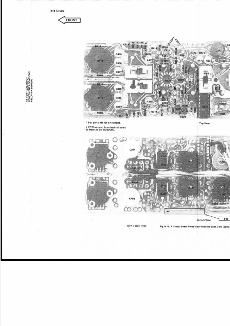
5/14/2018 Tektronix 214 Manual - slidepdf.com
http://slidepdf.com/reader/full/tektronix-214-manual 55/95
uu
e
co
ä
d
!
g
E
q
J
.
3
gP
z
3ö
q
E
o
ö
gB
!
-6
5
Ez
-
d
i
.€
-
h
:
;
oi
.
Yo
0
sNsMo
3
sNo
v
INS
o
o
rn
Nt'v
-u
A
v
*1
$i{ä'
IE
:
ö
_
q
]h
üG*

5/14/2018 Tektronix 214 Manual - slidepdf.com
http://slidepdf.com/reader/full/tektronix-214-manual 56/95
21
VOLTAGES ND WAVEFORMS
Th e voltages ndwaveforms hownon this diagramwereobtained by using the following test set-ups and testequipment.
VoltageMeasurements:
Set he front an dsidepanel ontrols o mid_range.
Input couplingsruitcheso ground (GND). Traceposi-tioned to the centerhorizontal ine.
Voltmeter common is conngcted o the. instrumentcommon.
WaveformMeasurements:
The 214 Oscilloscopeunder test: The frontpanel controls are set to mid-range. he input
suritches re set to AC. The verticaldeflection sswith a two millivolt squarewaveconnectedo CHtw o millivolt sinewaveconnectd to cH 2. Th e Sswitch sset or 0.5 m with a triggered isplay.
Test Oscilloscope:The test oscilloscope s itriggered; he vertical deflection and horizontal tindicatedon the waveform photo. The vertical npcoupled. The tolerance of the voltagesand wave2OoÄ. he test oscilloscopeused or the wave ormTektronix7503with a readout isplay.
RECOMMENDED EST EOU PMEN T
ITEM SPECIFICATIONS RECOMMENDEDYPE
Oscilloscope Frequencyresponse 00 kilohertz. Tektronix21 1or equivalent.
Voltmeternonloading gitalmultimeter
Input mpedance: 0 MO
Range:0-1kV
Tektronix7D 13 Digitalmultimtest oscilloscopewith readorequired.
FairchildModel7050or equiv

5/14/2018 Tektronix 214 Manual - slidepdf.com
http://slidepdf.com/reader/full/tektronix-214-manual 57/95
F&h soorreQ
e QEzOoeo
p c570orrcQ
J#"
tElltBi-el tsIGßl >i]
ß'3,1Fi
r(DC?!1)
---: l : :lli'i"
IT'LJ
l-"l " ol ' ol .I
Ti"Ll
[*l b
r l o
L,
.c$2t4 BCF
EXI
ttstDst
R!6tCt@k
PlatS9k
sk
vlmruFg
HORIZCINTER
"izitlffil-Y38
H'l
+VERT 5tOTO PrNtO, ffiDraog
-vEg stc DlaqTOPtN |, cRT (g
+ H4tZ 9t6TO PtN Cr CRTorre@
- aoRtz 916TO PIN 9, CRToreg
UNALA{KIN6SIGXAL cPrf, q, cRTDtaqO
R4826t
ffiBr-öfiH
* PART OF ETCHED CIrcUIT BOARD
PARAIAL AI,INPUT BARD
!n l(06p!, I -5.N
(ocEl)
I I f8l'f
| |
oerz)
L--=l\ i lßrN( | |Raqro;i_ J l
, _ : : i
cdPosEE Ttro atöFsM e$2
O
TO
H.",Tf.i'io+
as79
t'-Elagvswt@
oPrNN ruIL CCW OF
rw!l/sLoE mTl^l Aa, A$PLIF|ERaOARO
NOTE: FOR qOMPONENT LOCATIONSsee Fr6.9-r FOe At BOARO.
HoR.tz{veer uTpurs,TRIGGERswrre @
i4 : : ; s A\J : : : . .. : t L . t u n i ; . | |'
vGt rHAI+üiS cDr i - ' l - ' . c : r l l | | + 2 _ 2 vcENi tRj F i . ( ; : c i r j , j ti | | | ,/
f i l -
!S--.*o' "rroi. r
Dr aqo
lIh\ c*wx")+ORRAI
ELTsOPMERLYPZr, PrN
Rt32 &37rk
ii:ti
ta19
t @REV H DEC t'AO
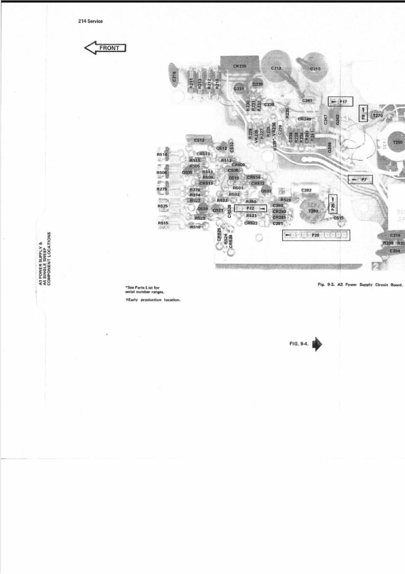
5/14/2018 Tektronix 214 Manual - slidepdf.com
http://slidepdf.com/reader/full/tektronix-214-manual 58/95
5 @o o
a
P
uES
V&
A
SN
ES
E
C
O
E
LcA
O
! r D ! F o @ r
gsEäräI 0
l F I P ?

5/14/2018 Tektronix 214 Manual - slidepdf.com
http://slidepdf.com/reader/full/tektronix-214-manual 59/95
H
l I (o I 5 ( t a o v { t ! t oo F D@q G@

5/14/2018 Tektronix 214 Manual - slidepdf.com
http://slidepdf.com/reader/full/tektronix-214-manual 60/95
RECOMMENDEDESTEOUIPMENT
SPECIFICATIONS
Frequency esponse 00 k ilohertz.
Input mpedance:0 MO
Range :0 - l kV
214
The voltages nd waveforms hownon this diagramwereobtained by using the following test set-upsand testequipment.
VoltageMeasurements:
Set he front an dsidepanel ontrols o mid-range.
Input couplingswitches o ground (GND). Trace posi-tioned o the center orizontal ine.
Voltmeter common is connected o the instrumentcommon.
Oscilloscope
Voltmeternonloading igitalmultimeter
ä {: rF ; .1 'l fiö r,q'9 ?9 * I I i, r r,e;
VOLTAGES ND WAVEFORMS
, : i . ! . ; i i - , . . i r : i ' i
Wavef rm Measurements
The 214 Oscilloscope nder test: The front apanel controls are set to mid-range. he input cswitches re set to AC. The verticaldeflection ssewith a two mill ivolt squarewaveconnectedo CHtwo millivolt sinewaveconnectedo CH 2. Th e Sswitch s set or 0.5 m with a triggered isplay.
Test Oscilloscope: he test oscilloscopes intriggered; he verticaldeflectionand horizontal i
indicated n the waveformphoto. The vertical npcoupled.The toleranceof the voltages nd wave2oo/o. he test oscilloscope sed or the wave ormTektronix7503with a readout isplay.
RECOMMENDEDYPE
Tektronix211 or equivalent.
Tektronix7D 13 Digitalmultimtest oscilloscope ith reado
required.
Fairchi ldModel 050or equiv
iI
i / . . - . , , . 1
' . . ',;.
1
' .1, . ;r- i
.- . ,.i' l
.i:I 1ä
\ r- * - - - i i - * " ^
6r' '+ far ;' |i . : 1 ' 7 . . f '.; . ' , . t , * , i , , - ,
! 1 5...-"..r.i....i 1, .iill ti; "1.i i._ -
i j ; { .
r. - {- erlrV
1'1, i ltrl
'' , a' ; '
' : . l , j ; . : :I l ; '
l
i, 1 .
l
*-
. J '
"€..i
i: ,
I'.1 ---
: i 1 . '
i
.1 . '
i i' {:,:.l ,
, :. ;
' 1 " - ., . i ! . " 1 . t ". " . i . - ; . : - " . , , i '
. l - - . - ' ' . ' - : ' i : . l t ' i i j : ! , ' r )1 . !a . i l i "? r ' l k', - , i t ' - i : r ; i : ' , ' ! . I :
r s !, : + t sr. ...\,,tflF . . :x-"1 . , , , , .. , . , . " *i , , . ' i : l
: . j - ri
t , . , , . i - *l ,
: " ' t # ' - * {l . . l '
.
: i : i : " ' : : . ,
i i :' : t ' j i '
':
: | , . . . , ! t t . -|
t . r ' i
+i* !;-J €- r
. f : , t . , . l . . e a - . .
. . i . - ',
' ir ; t..':r '{t' '.
'. !,' :
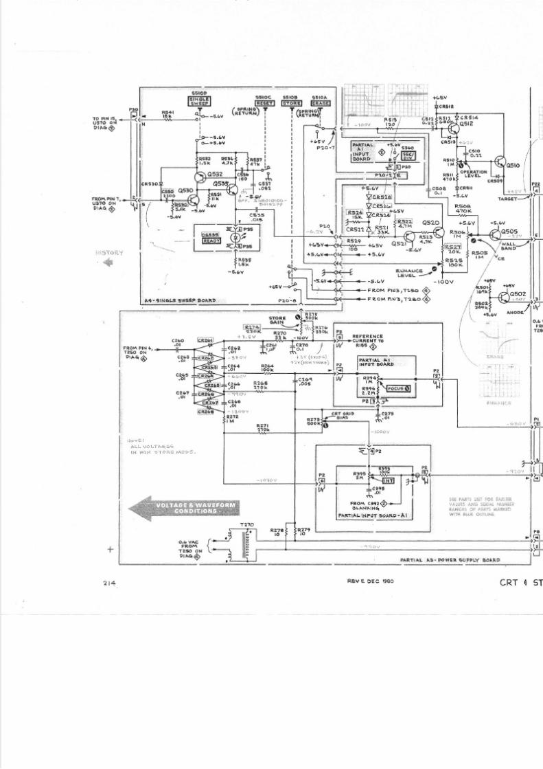
5/14/2018 Tektronix 214 Manual - slidepdf.com
http://slidepdf.com/reader/full/tektronix-214-manual 61/95
fc
, l̂ I *F I I eP I i
a
t+ ! o
gS
Ä o
'
a
*
"
#; i
N
lo
"?i3
t
r
o
i
i$
o 6
I ö
t9I
I I I
$
lLX
^
9
ie
!
f
h
"
f
P ö
T
Ä
ö
\*
"
to
!ü o i
I
'F $H
o o oAoY^=
I l*F+
ü-7'8
ö c
ni n 0 o
fq
;sl t<t>l I t
>l0 l3lald lFr
qt I l
@lo
t l"'| I I I LL
_
ä i*d
irü
r_
_
t
r
8
U
o - ( -
6
+
l
c
l
ü
l
* ssIt t
l
+
|
s
l
?* I
olu
l
r !g Fr !
1 -r t
-o
;
tu
i
-
\

5/14/2018 Tektronix 214 Manual - slidepdf.com
http://slidepdf.com/reader/full/tektronix-214-manual 62/95
214 Sewice
VOLTAGES ND WAVEFORMS
The voltages ndwaveforms hownon this diagram er eobtained by using th e fol lowing test set-upsand testequipment.
VoltageMeasurements:
Set he ront and side anel ontrols o mid-range.
Input couplingwvitcheso ground (GND).Traceposi-tioned o the center orizontal ine.
Voltmeter common is connected to the instrumentcommon.
WaveformMeasurements
The 214 Oscil loscope nder test: The front and sidepanel controlsare set to mid-range. he input couplingswitches re set to AC. The verticaldeflection s set o 1 mwith a two mil l ivolt square aveconnectedo CH 1 andatw o mil l ivolt sinewaveconnectedo CH 2. Th e SEC/DlVswitch
s set or 0.5 m with a riggered isplay.
Test Oscilloscope:The test os€illoscope s internallytriggered;he verticaldeflectionand horizontal iming isindicatedon the waveformphoto. The vertical nput is ACcoupled. The toleranceof the voltagesand waveforms s2O%.The test oscilloscope sed or the wave orms was aTektronix 7503 with a readoutdisplay.
B ECOMMENDED ESTEOU PMENT
ITEM SPECIFICATIONS RECOMMENDEDYPE
Oscil loscope Frequency esponse 00 kilohertz. Tektronix211 or equivalent.
Voltmeternonloading igitalmultimeter
Input mpedance:0 MO
Range:0 -1 V
Tektronix D1 Digi ta lmul t imeter,test oscilloscopewith readout isrequired.
Fairchi ldModel7050or equivalent.
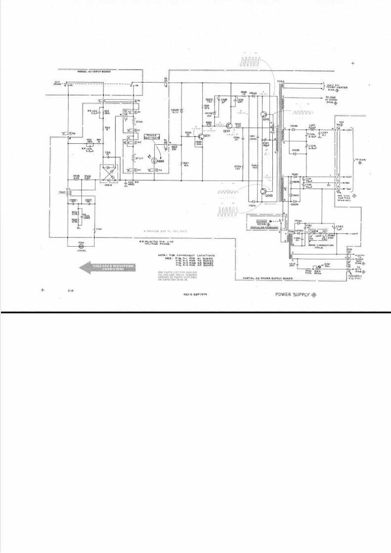
5/14/2018 Tektronix 214 Manual - slidepdf.com
http://slidepdf.com/reader/full/tektronix-214-manual 63/95
atrüL at- ll{PuT 90aF,0
r r l r r i l i i ' r l, r l J l l l l l , l j l
@?ft ,örlF+65v
t lt lt lt lt lt lilj-* +.ov
l' lF-sev
?'"??ii,",
JCL56
! czEe 6.aaF
0
F V, ) r . : f l . . iE P. i : 6 1 . !1t t, : i i t 1
rF*3eLEctED FoE LrusVöLTAGE TANG€I
NOE: FOR COMrcNENT aO.O-,Oatg E E 1 F l q , 9 - t F O R A t e o A R D
F I G . 9 - 2 FO R A2 R oA R DFIq . '-3 FOR A: bARDF I q , 9 . 4 F O ß A4 B OA R D
jgg :rr.*an r_i3 r i.!:q cr.äi. i[]11dr i ; : i J *S1 i;3t; i : ri tr!: i€f:t;N:ES {:t pA€T€ llj;i;:lti:.! ; b(: l {TfD iN Bl:,18.
II PARThLA3-PowERsuPPtYBl?llg
I
o ,a40
oreeQ
E;lE l)*llLIWI BlFt
I o,.u o.I AOCRT HEATER
/ D r a 6 O
. loc2@
DrasO
- - . . : , , . , aßi , i
REV G SEP I97< I POWER UPPLY

5/14/2018 Tektronix 214 Manual - slidepdf.com
http://slidepdf.com/reader/full/tektronix-214-manual 64/95
I
: oI
IIII
IIl o
I
!.
Section 8-214 Servi
REPLACEABLE
ELECTRICALPARTS
PARTSORDERINGNFORMATION
Replacement artsare avai lable ro m orthrough your localTektronix , nc. FieldOff ice
or representative.
Changes to Tektronix instruments are sometimes made to accommodate improved
components as they become available, an d to give you the benefit of the latest circuit
improvementsdeveloped n our engineeringdepartment. t is therefore mportant,when
order ing parts , o inc lude he fol lowing nformation n your order:Part number, nstrument
type or number, ser ial number, and modif icat ion number i f appl icable.
lf a part you have ordered has been replaced with a new or lmproved part, your local
Tektronix , nc. FieldOf f ce or representat ive i l l contactyo u
concerningany change n part
num ber .
Change information, if any, is located at th e rear of this manual.
SPECIALNOTESAND SYMBOLS
X000 Part irst addedat this serialnumber
00X Part emoved fter his serialnumber
ITEM NAME
ln the Parts List, an ltem Name is separated from the description by a colon (:).
Because of space limitations, an ltem Name may sometimes appear as incomplete. Fo r
further ltem Name identification, the U.S. Federal Cataloging Handbook H6-1 can beuti l ized where possible.
ABBREVIATIONS
IIIII
ACTR ACTUATORASSY ASSEMBLYCA P CAPACITORCER CERAMICCKT CIRCUITCOMP COMPOSITIONCONN CONNECTORELCTLT ELECTROLYTICELEC- ELECTR]CALINCAND INCANDESCENT
LED LIGHTEMITT{NG IODENONWIR NONWIREWOUND
PLSTC
QTZRECP
RE S
RF
SE L
SEMICOND
SENSVA R
WW
XFMBXTAL
PLASTICQUARTZRECEPTACLERESISTORRADIOFREQUENCYSELECTEDSEMICONDUCTORSENSITIVEVARIABLEWIREWOUND
TRANSFORMERCRYSTAL
8

5/14/2018 Tektronix 214 Manual - slidepdf.com
http://slidepdf.com/reader/full/tektronix-214-manual 65/95
eplaceableEleclrlcal Parts-2l4 Servlce
Mfr.Code Manufacturer
CROSSNDEX-MFR. ODE UMBEROMANUFACTURER
Address City, tate, ip0 1 1 2 10 l 295
03508
038880471307263
1t237r4433
r475216546
270L4329975t6425628971450729827 3 1 3 8759176493
79727800098003844190201
9r637
ALLEN-BRADLEY COMPANYTEXAS INSTRI]MENTS, NC., SEMICONDUCTORGROUPGENERALELECTRIC COMPANY,SEMI-CONDUCTOR
PRODUCTSDEPARTMENTKDI PYROFILM CORPORATIONMOTOROLA, NC., SEMICONDUCTORROD. DIV.FAIRCHILD SEMICONDUCTOR, DIV. OFFAIRCHILD CAMERAAND INSTRTMENTCORP.cT S KEENE, INC.ITT SEMICONDUCTORS
ELECTROCUBE INC.U. S. CAPACITORCORP/CENTRALABELECTRONICS IV .NATIONAL SEI'TICONDUCTORORP.BOURNS,rNC., TRTMPOTPRODUCTS rV .CENTREENGINEERING NC.SPRACUE LECTRIC CO .cT s coRP.ERrE TECHNOLOGTCALRODUCTS, NC.BECKMANNSTRIJMENTS,NC., HELIPOT DIV.LITTELFUSE, INC.BELL INDUSTRIES, NC. ,M I L L E R , J . W . , D I V .C-I.l INDUSTRIESTEKTRONIX, INC.ELECTRA-MIDLAND ORP., MEPCODrV.TRI{ ELECTRONICCOMPONENTS, RI.I CAPACITORSMALLORYCAPACITORCO., DrV. OFP. R. MALLORY ND CO., rNC.DALE ELECTRONICS, NC.
12OI 2ND STREETSOUTIIP O BOX 5012, 13500 N CENTRALEXPRESS}JAY
ELECTRONICSPARK60 S JEFFERSONROAD5005 E MCDOI{ELLRD,PO BOX 20923
46 4 ELLIS STREET3230 RIVERSIDE AVE.3301 ELECTRONICS {A YP O BO X 304917 IO S. DEL MARAVE.
4561 coLoRADo29OO SEMICONDUCTORR.I2OO COLUMBIAAVE.2820 E COLLEGEAVENUE
905 N. I{EST BLVD644 W, t2Trr ST.25OO HARBORBLVD.8OO E. NORTHI.IESTIT{Y
MILI'IAUKEE WL 53204
DALLAS, TX 75222
SYRACUSE, Y 13201WHTPPANY, J 07981PTIOENTX,AZ 85036
MOUNTAINVIEhI, CA 94042PASO ROBLES, CA 93446
I{EST PALI'I BEACII, FL 33402sAN GABRTEL,CA 91776
LO S ANGELES,CA 90039SANTA CLARA, CA 95051RMRSTDE, CA 92507STATE COLLEGE, PA 16801NORTHADAMS, t4A 01247ELKIIART, rN 46514E R I E , P A 1 6 5 1 2FULLERTON,CA 92634DES PLATNES, rL 60016
19070 REYESAVE., P O BO X 5825 COMPTON, IL90224550 DAVISVTLLERD.,p O BOX 96 I{ARMTNTSTER,A 18974P O BOX 500 BEAVERTON,OR 9707722 COLUMBIA ROAD MORRISTOhIN,NJ 07960ll 2 I. l . FIRST ST . OGALLALA,NE 691533029 E. I{ASIIINGTONSTREETP. O. BOX 372 TNDIANAPOLTS, N 46206P. O. BOX 609 COLUIiBUS, itE 68601
-2 REVH, MAY 198

5/14/2018 Tektronix 214 Manual - slidepdf.com
http://slidepdf.com/reader/full/tektronix-214-manual 66/95
Replaceable lectrlcalParte-214Se
TektronixCktNo, Part o.
Ser ia l /Modelo.Ef f Dscont Name Description
MfrCode MfrPartNum
I
: oI
IIII
tIl o
I
f.
AIA IAIA IA2A3
670-2353-01670-2353-03670-2353-05
670-2353-07670-l 505-02670-2741-OO
670-274t-I l670-2741-21
B 0 l 0 l 00 8055618055612 80899998090000 8099999
B100000B010100 8049999
B050000
8010100 8059999
8060000
8010100 80668268066827
8010100 8066826B0668278010100 8066826
283-0180-00 8,066827283-0263-00
283-0279-00
283-0057-00 B0l0 l00 Bo5l099285-1065-00 B051 00283-0057-00 8010100 8051099281-1065-00 B 05 t 00285-0925-00
285-0933-00
28s-0935-00
285-0925-00
285-0933-00
285-0935-00
BOARDASSY: NPUTBOARDASSY: NPUTBOARDASSY: NPUT
BOARDASSY: NPUTBOARD SSY:AMPLIFIERBOARDASSY:POI{ER SUPPLY
CKT BOARDASSY:POtfERSUPpLyCKT BOARDASSY:POI.IERSUPPLY(oprrou t onl,y)CKT BOARDASSY:POI{ERSUPPLY(oprron 2 oNLy)CKT BOARDASSY:SINGLE STTIEEP
CK T BOARDASSY:SINGLE SI{EEP
BATTERY SSY:2 SETS OFBATTERY SSY:2 SETS OF
CAP. FXD,CER DI :0 . IUF , 20U,50VC A P . , F X D , C E R I : 0 . 1 U F , 0 2 , 5 0 VCAP. ,FXD,CERDI : 5600PF,202 ,200VCAP. FXD,CER DI : 5600PF 207" 200VC A P . , F X D , C E R I : 0 . l U F , 2 0 Z , 5 0 VCAP. FXD,CE R DI : 0. IUF 202 50 V
CAP. ,FXD,ELCTLT4. 7UF,202 , 0VCAP.,FXD,ELCTLT 4. 7UF,202, l }VCAP. FXD,ELCTLT:UF 2OZ 5OVCAP. ,FXD,CERDI : 5600PF,202 ,200VCAP.,FXD,CERDI : 5600PF,2O"A,2OOVC A P . , F X D , C E R I : 5 6 0 0 P F , 2 O Z , ? O O V
CAP.,FXD,CER DI : 5600PF, OZ, IOOVCAP.,FXD,CERDI : 0 .0022UF,202 , 3000V(llourxll VALUE, SELECTEDFoR LrNE voLTAcE ANDFREQUENCY. EE oprroN tnronuarron)
C A P . , F X D , C E R I : 0 . 0 0 l U F ,2 0 2 , 3 0 0 0 V
(nournel VALUE, SELECTEDFoR LrNE voLTAcE ANDFREQUENcv.sEE op r rNFoRMATroN. op r I oNLy)
CAP. ,FXD,CERDI : 0 . lUF,+80 -2OZ,?OOVCAP. FXD,PLSTC: .OIUF,20U ,600VcAP. , FXD,CERDI : 0 . lUF,+80-2OZ,ZOOVCAP. FXD,PLSTC0.OIUF 2O"A600VCAP. ,FXD,PLSTC3. 3UF,102 ,200V(nournAl VALUE, SELECTEDFoR LrNE VoLTAGE AND
FREQUENCY. SEE OPTTONTNFORMATTON)
CAP. ,FXD,PLSTC2UF, 0Z , 400V(r,tourua,l vALUE, SELEcTED FoR LrNE votrAcE ANDFREQUENcv. sEE opr rNFoRMATroN. opr I oNLy)
CAP. FXD,PLSTC4 . 4UF, 0Z 200V(nournu vALUE, SELEcTEDFo R LrNE voLTAcE ANDFREQUENCv.SEE OpT INFORMATION.OpT 2 Oltty)
CAP. ,FXD,PLSTC3. 3UF, 0Z, 200V(nournal vALUE, SELEcTEDFo R LrNE voLTAGE ANDFREQUENCY. sEE oprroN rNFoRI.tATroN)
CAP. ,FXD,PLSTC2UF,102 ,400V(nournel VALUE, SELECTEDFoR LrtfE VoLTAGE ANDFREQUENCY. EE OpT INFORMATION.OpT I Ottty)
CAP. FXD,PLSTC4.4UF, I 02 200V(nournal vALUE, SELEcTED FoR LrNE voLTAcE ANDFREQUENCY. EE OpT INFORI.TATION. pT 2 Oltty)
80009 670-2353-0180009 670-2353-0380009 670-2353-05
80009 670-2353-0780009 670-1505-0280009 670-274t-OA
80009 670-274L-tr80009 670-274t-21
80009 670-274t-31
80009 670-2676-00
80009 670-2676-0I
80009 146-0033-0080009 r46-0033-00
72982 8l2l-N088Z5ULO72982
8t2l-N08825U172982 39300125v056272982 8121N204 56272982 8121-N08825U172982 8l2l-N088Z5Ul0
90201 TDC475n0loEL90201 TDC475M0loEL56289 l96Dl05x0050nA72982 39300125v056272982 8121N204 56272982 39300125v0562
72982 8121N204 56256289 33C319
s6289 55c153
56289147525628914752844rr
274Ct0230B l F l 03274Ct0230B l F l 03TEKI2 -33592
r4752 A-1480
56289 430P179
84411 TEKl2l -33592
14752 A-1480
56289 430P179
CKTCKTCKT
CKTCKTCKT
A3A3
A3
A4 670-2676-00
A4 670-2676-0r
BT2l6 146-0033-00BT2t7 146-0033-00
c10 l 283 -01l -00c l 03 283-0111-00
c104 281-0591-00cl04 283-0180-00c I l 3 283 -0 l l l - 00c l l 5 2 8 3 - 0 1 1 1 - 0 0
c t25 290-0524-00ct27 290-05?4-00cI29 290-0522-00c l 50 281-0591-00cl50 283-0180-00c l 53 281-0591-00
670-274I-31
c l 5 3c204
c204
c206c206c207c207c 2 l 0
c2 l 0
c 2 t 0
c z t 2
c 2 t 2
czt2
55
IIIIt
REVH, MA Y1980 8

5/14/2018 Tektronix 214 Manual - slidepdf.com
http://slidepdf.com/reader/full/tektronix-214-manual 67/95
ReplaceableEleclrical Parts-2l4 Service
TektronixSer ia l /Modelo.CktNo. PartNo. Eff Dscont Name Descript ion
MfrCode MfrPartNumber
c2I5
c 2 1 5
czr6c236c238c239c24lc247
c25lc253c256c257c258c260
c26rc262c263c264c265c266
283-0263-00
283-0279-OO
CAP. FXD,CER DI : 0 .0022UF 20143000V(ttourl'rel VALUE, SELECTEDFoR LrNE VOLTAGEAND
FREQUENCY. SEE OPTION INFORMATION)CAP. ,FXD,CERDI : 0 . 001UF,207" ,3000V
(nournu, vALUE, SELEcTED FoR LrNE voLTAGE ANDFREQUENCY.SEE OPT INFORMATION.OPT I ONLY)
C A P . , F X D , C E R I : 0 . 0 l U F ' + 1 0 0 - 0 2 , 5 0 0 VcAP. , FXD,CER Dr : 0 . 0 luF ,+ 80-207",L50VCAP. FXD,ELCTLT: UF , 207"35 VCAP. ,FXD,ELCTLT0.47UF, 0Z ' 35VCAP. FXD,CE R DI : 0. 0022UF 20i( ,50VCAP., FXD,ELCTLT l00UF, 202,20V
CAP. FXD,ELCTLT:33UF 207" LO VCAP., FXD,ELCTLT 33UF,2O7",OV
CAP. FXD,ELCTLT 6. 8U F 2Ai4 35VCAP. ,FXD,CERDI : 0. lUF,+80-2OZ,?OOVCAP. FXD,ELCTLT 6 . 8UF 2O'4 35 VC A P . , F X D , C E R I : 0 . o l U F , + 1 0 0 - 0 2 ,5 0 0 V
c A P . , F X D , C E R r : U F , + 8 0 - 2 0 % , 2 5 V
C A P . , F X D , C E R I : 0 . O I U F , + 1 0 0 - 0 2 , 0 0 VC A P . , F X D , C E R I : 0 . 0 1 U F ' + 1 0 0 - 0 2 ' 0 0 V
c A P . , F X D , C E R r 0 . 0 1 U F , + 1 0 0 - 0 2 , 0 0 v
c A p . , F x D , c E R D r : 0 . o l u F , + 1 0 0 - 0 2 , 5 0 0 vc A P . ,F X D , C E R r 0 . 0 l U F , + 1 0 0 - 0 2 ,5 0 0 v
C A P . , F X D , C E R I : 0 . 0 l U F , + 1 0 0 - 0 2 ,5 0 0 Vc A P . , F X D , C E R r : 0 . 0 1 U F , + 1 0 0 - 0 2 , 5 0 0 vC A P . ,F X D , C E R I : 0 . 0 0 5 U F , + 1 0 0 - 0 2 , 5 0 0 VCAP. FXD,CE R DI :0. IUF 202 50VCAP. ,FXDTCER I : 0 . 01UF,+ 80-207 , 2000V
C A P . , F X D , C E R I : 0 . l U F , 2 0 2 ,5 0 V
C A P . , F X D , C E R I : 0 . l U F , 2 0 % , s O VCAP. ,FXD,ELCTLT lUF,+50-102, 150VCAP. FXD,PLSTC0. lUF, +5- l 5U 600VNTT{K,HYBCKT:
(TURITSNNDAS A UNIT I.TITHR3O6A-F)CAP. ,VAR, LSTC l -3 . 5PF '500V
CAP. ,VAR, LSTC 1-3. 5PF' 500VCAP. ,VAR,PLSTCl-3. 5PF,500Vc A P . , F X D , C E R r 0 . 0 0 1 u F , + 1 0 0 - 0 2 , 5 0 0 vC A P . F X D , C E R I : 1 2 P F , 5 2 , 0 0 VCAP. FXD,CE R DI : 8 . zP F + -0 . 25PF,500VcAp. , FxD,CER Dr : 8 . ZPF,+ ' 9 .25PF , 500V
CAP, FXD,CERDI : 0 . lUF, 202 , 50VCAP. ,FXD,ELCTLT68UF,2OZ,6VC A P . F X D , C E R l : 2 7 0 P F , 5 2 ' 1 0 0 0 V
C A P . , F X D , C E R I : 2 7 P F , 0 2 , 5 0 0 VCAP. FXD,ELCTLT 4. 7UF,202 lOV
CA P SET,I, IATCHED:UF'0. 00lUF'MATCIIED
rc362,C363,C364, TNDTVTDUALTMTNGCAPACTTORS
IN THISASSY MUST BE ORDERED Y THE g-DIGIT
PART NT'II{BER,LETTER SUFFIX AND TOLERANCE
PRINTED ON THE TIMING CAPACITORS N TH E
AssEltBLY. exAltpln: 285-xxxx-xx r -)
CAP. ,FXD,CERDI : 0 . 0 lUF , 20"ÄsOVC A P . , F X D , C E R I : 8 7 P F , 5 Z ' 0 0 V
CAP. FXD,ELCTLT:2.ZIJF20"4,20V(pmt OF CIRCUIT BOARD)c A P . , F X D T C E R r : 0 . 0 1 U F , + 1 0 0 - 0 2 , 0 0 v
56289 33C319
56289 55C153
56289 l9g24r72982 855-55825U-103256289 I96D105X0035HA156289 r62D474X90358C256289 19c6069020I TDCt07M02ot{LD
56289 r96D336X00lOKAI56289 196D336x0010KA156289 196D685X0035KA156289 274Cr056289 196D685X0035KA156289 L9C24r
56289 273C5
56289 l9024r56289 l9024r56289 L9C24r56289 t9g24r56289 l9024l
56289 r9024r56289 r9g24r72982 831-559E502P72982 8121-N088Z5Ul04M56289 4lC3l672982 8121-N08825U104M
72982 812I -N08825U104M56289 500Dl05Fl50BA780009 285-0697-0680009 307-0307-01
80031 2805D013R5BI to2F
80031 2805D013R58tt02F080031 2805D0l3R5Blto2F072982 831-5168102P72982 8l0 lB l21C0G0120J72982 374018C0H0829C72982 374018C0H0829C
72982 8121-N088Z5Ul04M9020r rDc686M006NLF72982 838-533B27rJ56289 40C287A290201 TDC475M0lOEL8441 TEKI0 l -0009R5
283-0068-00283-0003-00290-0534-00290-0283-00283-0028-00290-05 9-00
290-05 5-0290-0535-0290-051 -00283-0057-00290-05 7-00283-0068-00
283-01 7-00283-0068-00283-0068-00283-0068-00283-0068-00283-0068-00
c267 283-0068-00c?68 283-0068-00c269 283-0001-00c270 283-01 l-00c273 283-0105-00c280 283-01 1-00
c28l 283-01 1-00c282 290-0164-00c301 285-0697-06c3068, 307-0307-01
c306D,Fc307 281 -0178-00
c308 281-0178-00c309 281-0178-00c3 l3 283-0000-00c32r 283-0168-00c323 281-0645-00c323 281-0645-00
B 010100 8052541B052542
c327c329c348c349c 3 5 3c3621c36 l
$641
283-01 1-00290-0530-00283-0084-00283-0076-00290-0524-00295-0r44-00
283-0204-00283-0251-00 X 8055612290-0523-00
c368c 3 7 0c37c372c373
72982 8I21N06125U0103M72982 81218145C0G0870J56289 196D225X002ottA1
56289 r9g24r
8-4
283-0068-00
REV , MAY 1980

5/14/2018 Tektronix 214 Manual - slidepdf.com
http://slidepdf.com/reader/full/tektronix-214-manual 68/95
I
: O cktNot _
Tekt ron ixSer ia l /Mode lNo,PartNo. Eff Dscont Name Descr ip t ion
ReplaceableElectrlcal Parts-214 Serv
MfrCode MfrPartNumbe
c374c376
I liii383
I !il;401
I ti8ät:,c407c408
r iili423
I .'ilc49lc493
I :;r3c5I2
loi i i 'c536
I c.*.cR21
I :ä;i?r :ffi1cRz53
I :#:cRz58
r :13:lI cR262
cR262
I :iiliR264cR265
I :l;:;cR266
I iülir O
cR26B
I
290-0523-00290-0534-00283-0068-00
283-0000-00283-0000-00283-0 1-00
283-0103-00283-0087-00283-00 3-00285-069 -06
131:3'!11128 l -0 I78 -00281-0 78-00281-0 I78 -00283-0000-00283-0168-00281-0612-00 B 0 l 0 l 00 B 052541
281-0612-00 B;052542290-0524-00290-05 5-00290-0535-00283-0 78-00283-0198-00
283-0208-00283-006 -00283-0197-00 8010100 8059999283-0176-00 8060000283-0268-00283-01 9-00
283-0326-00
152-0488-00
I 52-014 -02152-0141-02t52-Ot4L-02I 52 -0141-02I 52-0141-02
I 52-0 41-02I 52-0333-00l 52-0333-00152-0107-00 8010100 8029999152-0107-03 8030000152-0107-00 B0l0 l00 8029999
152-0107-03 8030000152-0107-00 B0l0 l00 B029999152-0107-03 8030000152-0107-00 B0l0l00 8029999
152-0107-038030000
r52-0107 '00 B0l0 l00 8029999
t52-0107-03 8030000152-0107-00 8010100 B029999r52-0107-03 8030000152-0107-00 B0l0 l00 8029999r52-0107-03 8030000152-0107-00 8010100 8029999
I52-0107-03 8030000
CAP. FXD,ELCTLT2.2 lJF 2O%,zOYCAP. ,FXD, LCTLTlUF, 2O Z,35Vc A P . , F X D , C E R r 0 . 0 l U F , + 1 0 0 - 0 2 , 5 0 0 v
cAP. ,FXD,CERDr : 0 .001uF ,+ 100-02 , 500vc A P . , F X D , C E R r : 0 . 0 0 I U F , + 1 0 0 - 0 2 r 5 0 0 vC A P . , F X D , C E R I : 0 . l U F , 2 0 % , 5 0 V
CAP. ,FXD,CERDI : 180PF, 2 , 500VC A P . , F X D , C E R I : 3 0 0 P F , I 0 7 " , 1 0 0 0 VCAP. ,FXD,CERDI : 0 . 0 lUF ,+ 100-02, 1000V
cAP. ,FXD,PLSTC0. lUF ,+ 5-152 ,600VNTI.IK,HYB CKT:(rurutsurD As A uNrr I{rrH n+ooe-r)
CAP. VAR,PLSTC:-3 .5PF ,500VCAP. ,VAR,PLSTCI -3 . 5PF ' 500VCAP. VAR,PLSTC:-3 .5PF ' 500VC A P . , F X D , C E R I : 0 . 0 0 I U F , + 1 0 0 - 0 2 , 5 0 0 VCAP. ,FXD,CERDI : l 2PF , 5Z ' l 00VC A P . , F X D , C E R I : 5 . 6 P F , + -0 . 5 P F ' 5 0 0 V
CA P , FXD,CER DI : 5 .6P F + / '0. 5PF, 500VCAP. ,FXD, LCTLT4 . 7UF,202 , OV
CAP. ,FXD,ELCTLT33UF,202 ' 10V
cAP., FXD,ELCTLT 33UF,2O"4,IOVcAP. ,FXD,CERDr : 0 . lUF ,+ 80-202 , l00vCAP. ,FXD,CERDI : 0. 22UF,20"4 ,50V
C A P . , F X D , C E R I : 0 . 2 2 U F , 0 U , 0 0 V
C A P . , F X D , C E R I : 0. 0 0 l U F ' 0 Z , 2 0 0 V
CAP. ,FXD,CERDI : 470PF,52 , 100V
CN.,FXD,CER Dl : 0 . 0022UF,20"Ä ,50VC A P . , F X D , C E RI 0 . 0 1 5 U F , 0 Z , 5 0 VC A P . , F X D , C E R I : 5 0 P F , 2 O Z , 5 O V
C A P . , F X D , C E R I : 0 . 0 8 2 U F , 0 2 , 5 0 V
SEUICOND EVICE SILICON,200V, 500MA
SEMICOND EVICE SILICON,30V, I 50MASEMICOND EVICE:SILIGON,30V I 50MASEUICOND EVICE:SILICON,30V, 150MA
SEI,I ICONDBVICE SILICON,30V, 150M4SEI,IICOND EVICE:SILICON,30V , l50MA
SEMICOND EVICE SILICON, 30V, l50l'{ASEI'IICOND EVICE SILICON,55V ,200MASEUICONDDEVICE SILICON, 55V' 200MA
SEI'IICOND EVICE SILICON, 400V, 4001'lASEUICOND EVICE SILICON,375V'4OOMA,SELSEMICOND EVICE SILICON,400V,400MA
SEMICOND EVICE SILICON,375V 4OOMA, ELSEI'{ICOND EVICE SILICON, 400V'4001'IASEMICOND EVICE SILICON,375V,4OOMA, ELSEUICONDDEVICE SILICON,400V' 4001'{ASEMICONDDEVICE SILICON, 375V'4OOI'{A, EL
SEI'{ICOND EVICE S LICON, 400V' 400MA
SEUICOND EVICE SILICON' 375V'4OOMA,SELSEMICOND EVICE SILICON, 400V'400I'{ASEUICOND EVICE SILICON' 375V'4OOMA'SELSEMICOND EVICE SILICON,400V,400MASEI' { ICOND EVICE SILICON,375V,400MA'SELSEMICOND EVICE SILICON,400V,400!' lA
SEMICOND EVICE SILIGON'375V'4OOMA,SEL
56289 196D225X0020H56289 l96Dl05X0035HA56289 l9024l
72982 831-5168102P72982 831-516E102P72982 8l2I-N088Z5urp4
56289 40C63856289 40363756289 33C29A780009 285-0697-0680009 307-0307-01
80031 2805D013R58H080031 2805D013R58H08003I 2805D0l3R5Brr072982 831-5168102P72982 810lB l2 lC0c0 l2072982 374-001C0H056
72982 374-001C0H0569020r TDC475M0IoEL56289 196D336X00I0KA56289 t96D336x00loKA72982 813rNr4565I IO472982 8121N08325V022
72982 8151N230C 224K72982 835-5 l5B l02K72982 8l2lN075C0G04772982 8l 2lB058X7RO2272982 8121N083X7R0151642 Wl00-050-X5Fl5t
16546 Clr20C823K
047T3 3N55 FAMILY
01295 l N4 t52R01295 lN4I52R01295 l N4 l 52R01295 l N4 l 52R01295 lN4I52R
01295 l N4 t52R07263 FDH-601207263 FDH-601201295 c72780009 152-0107-0301295 c727
80009 152-0107-0301295 c72780009 152-0I07-030r295 c72780009 152-0107-030 1 2 9 5 c 7 Z 7
80009 152-0107-0301295 c72780009 r52-0107-0301295 G72780009 152-0107-0301295 c727
80009 152-0107-03
RE VJ, JAN 1981 8

5/14/2018 Tektronix 214 Manual - slidepdf.com
http://slidepdf.com/reader/full/tektronix-214-manual 69/95
ReplaceableElectrical parts-214 Servlce
TektronixCktNo. Part o.
Ser ia l /Modelo.Eff Dscont Name Description
MfrCode MfrPar tNumbe
cR280 152-0107-00cR280 152-0107-03cR28l 152-0107-00cR28l 152-0107-03cR313 152-0246-00cR342 152-0141-02
cR343 152-0141-02cR346 152-0141-02cR383 152-0141-02cR389 t52-Ot4I-02cR4l3 r52-0246-00cR446 t52-Ot4t-02
cR509 I52-OI4L-02cR5 l l 152 -0107-00cR5l2 152-0107-00cR5l3 152-Ot4t-02cR5l4 152-0107-00cR522 152-0141-02
cR524 152-0141-02
cR526 152-0141-02cR528 r52-Ot4r-02cR530 152-0141-02
DS3l0 150-1004-02D S 3 1 0 1 5 0 - 1 0 3 1 - 0 rDS 320 150- r061 -00DS420 150-1061-00DS535 150-1004-03DS 535 r50 -1031-02
80r0100 804071280407 3B0l0l00 Bo407t280407 3
x8050000
x8050000x8050000
8010100 80545798054580
x8090000xB090000B 0r0 r00 80545798054580
B0 l0 l00 80899998090000
B0r0 l00 8089999B090000
01295 c72780009 I52-0107-030t295 C72780009 152-0107-03
03508 D81400 I295 l N4152R
01295 tN4l52R01295 l N4 t52R01295 1N4I52R01295 lN4t52R03508 D814001295 l N4 l 52R
0L295 lN4l52R01295 c7270t295 c7270t295 lN4l52R01295 c72701295 tN4 l 52R
01295 IN4152R01295 IN4152R01295 lN4l52R01295 lN4152R
80009 150-r004-0280009 150-1031-01270t4 sJ6277527014 sJ6277580009 150-1004-0380009 150-1031-02
75915 212.400
80009 129-0398-0080009 129-0398-00
76493 02279
76493 0227976493 01872
1 5 9 - 0 r 2 1 - 0 0
I 29-0398-00I 29-0398-00
108-069-00
108-069-0 0108-0654-00
108-0756-00I 08-0756-00
l 5 -0432-00r 5 -0432-00l 5 -0432-00l 5 -0432-0015 -0432-00l 5 t -0341 -00
I 5 -0220-00l5 l -0334-00l 5 -0334-00151-1072-00l 5 l - 1 0 5 7 - 0 0
r 5 -0341-00
151-0341-00151-0341-00l 5 -0504-00I 5 -0432-00t5 l -1072 -00l 5 l - 1 0 5 7 - 0 0
SEMICOND EVICE SILICON,400V,400l, tASEMICOND EVICE SILICON,375V,4OOMA,SELSEMICOND EVICE SILICON,400V 400MASEMICOND EVICE SILICON,375V,4OOMA, EL
SEMICOND EVICE SI{,SI,40V, 200}fASEMICOND EVICE SILICON,30V, 50MA
SEMICOND EVICE SILICON,30V, 150l, IASEMICOND EVICE SILICON,30V, I50MASEMICOND EVICE SILICON,30V, I 50MASEMICOND EVICE SILICON,30V, 50l, IASEMICOND EVICE SI{,SI,40V, 200M4SEI' iICONDDEVICE SILICON, 30V, I 50MA
SEI' I ICOND EVICE SILICON,30V, 50MASEI'{ICOND EVICE S LICON,400V ,400MASEMICOND EVICE SILICON,400V,400MASEI'{ICOND EVICE S LICON, 30V 150},tASEI'{ICOND EVICE SILICON, 400V r400MASEMICONDDEVICE S LICON, 30V, I 50I'{A
SEUICOND EVICE:S LICON,30V, I 50MASEMICOND EVICE SILICON,30V, I 50MASEI'{ICOND EVICE SILICON, 30V, 150MASEMICOND EVICE:SILICON,30V, I 50MA
LT EUITTING DIO:RED,1sMA,W/ttOlpnn & LEADSLAMP,LED:W/DIODE,I{rrREND CONNLT EMITTING DIO: RED,660NM, 0l,IAMttJKLT El'tITTINc DIO: RED,660NM, 0M A MAIKLT EI,I ITTINGDIO:RED,t5Ue,W/IIOLDER LEADSLAMP,LED:I{ /DIODE,WIRE ND CONN
FUSE CARTRIDGEDI N r0 .4A,250V ,5 SE C
POST,CONTACT:FORAC K TI pPOST,CONTACT:FORAC K TI p
CO IL ,RF : .8MH
COIL, RF : .8lf i lC O I L , R F : 2 . 2 M H(r'unnrsunDSA unrr wrru cnr)COIL,TUBE DEFLE:GEOMETRYORRECTIONCOIL,TUBE DEFLE:GEOMETRYORRECTION
TRANSSTOR S LICON, NPNTRANSSTOR S LICON, NPNTRANSSTOR S LICON, NPNTRANSISTOR S LICON, NPNTRANSSTOR S LICON,NP NTRANSISTORS LICON, NPN
TRANSSTORS LICON, PNPTRANSSTOR S LICON, NPNTRANSSTOR SILICON,NP NTRANSSTOR S LICON, JFE, P.CHAN,DUALTRANSISTOR:ILICON,FE,N-CHANNEL, UAL.TRANSSTORS LICON, NPN
TRANSSTOR S LICON, NP NTRANSSTOR S LICON, NPNTRANSISTOR SILICON, N-CHAN,UNIJUNCTONTRANSSTOR S LICON, NPNTRANSSTOR:SILICON,JFE , P-CHAN,DUALTRANSISTOR:ILICON,FE, N-CHANNEL,DUAL
108-0756-00108-0756-00
80009 l5 l -0432-0080009 I5 l -0432-0080009 l5l-0432-0080009 151-0432-0080009 l5 l -0432-0007263 S040065
07263 s03622880009 l5r-0334-0080009 r5 l -0334-0080009 l5 l -1072-0080009 l5 l - r057-0007263 S040065
07263 S04006507263 5040065047t3 2N485180009 t5r -0432-0080009 l5 l - I072-0080009 l5 l - r057-00
8000980009
20 l
J348J349
r l 0 8
L l l lL257L300L528L529
Q 0 7Q l r 0Q r eQr22Q 1 3 4Q23
Q 2 3 5Q242Q24eQ3 4Q 3 l 4Q326
Q328Q380Q388Q392Q414Q414
8-6 RE VL, JA N 1981
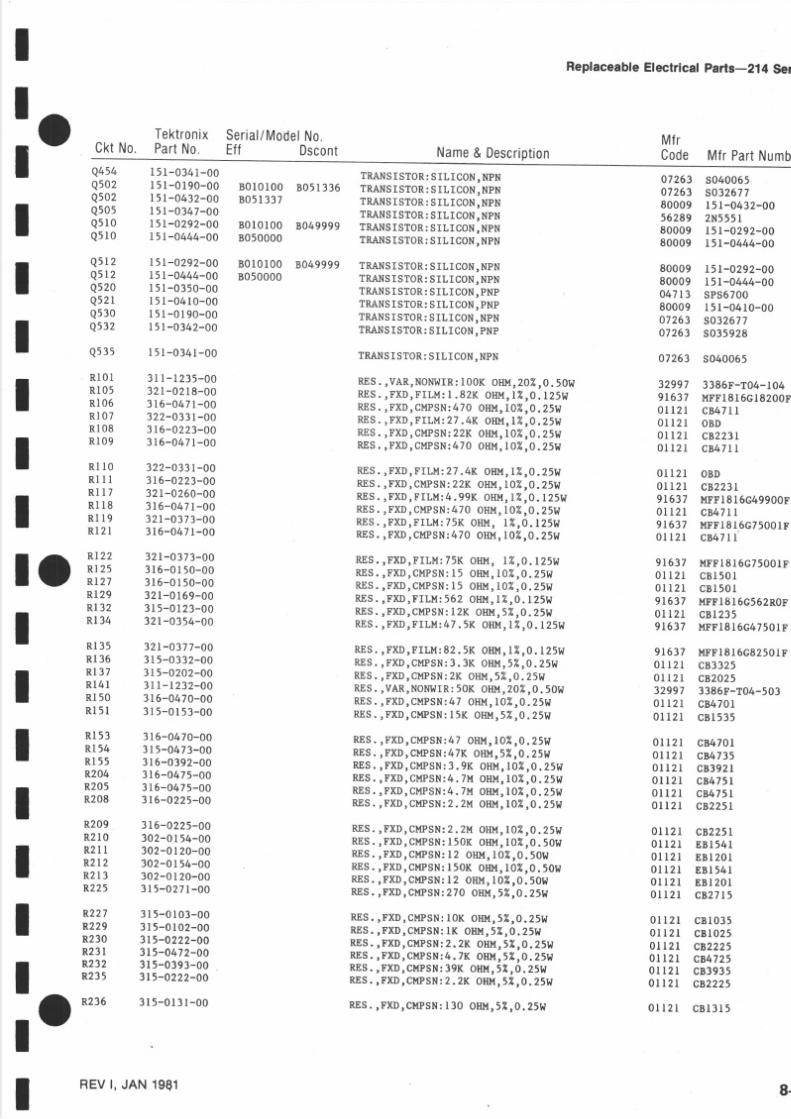
5/14/2018 Tektronix 214 Manual - slidepdf.com
http://slidepdf.com/reader/full/tektronix-214-manual 70/95
ReplaceableElectrical parts-2l4 Ser
CktNo.TektronixPart o.
Ser ia l /Mode lo .Eff Dscont Name Descr ip t ion
MfrCode MfrPartNum
I
_ oI
IIII
II
Q454Q502Q502Q505
Q s l 0Q 5 1 0
Q 5 1 2Q s 2Q520Q52Q53oQ 3 2
Q 5 5
R l 0 lR l 05Rt06Rl07Rl08
R l 09R l 0R l l lR l 1 7R l 8R l l 9R l 2 l
I 5 -0341-00I 51-0190-00l 5 -0432-00I 5 -0347-00
l5 1 -0292-00I 5 -0444-00
I 5 -0292-00I 5 -0444-00I 5 -0350-00r5 t -0410-00151-0190-00I 5 -0342-00
151-0341-00
3 l -1235 -00321-0218-00316-0471-00322-033 -003 6-0223-00
316-0471-00322-033-003 6-0223-0032 -0260-00316-047-0032 -0373-003 6-0471-00
321-0373-003 6-0r 50-00316-0150-00321-0169-00315-0123-00321-0354-00
32 l -0377-003 5-0332-003 5-0202-003 l -1232 -003 6-0470-00315-0153-00
3 6-0470-003 5-0473-00316-0392-00316-0475-00316-0475-003 6-0225-00
3 6-0225-00302-0 54-00302-0 20-00302-01 4-00302-0 20-00
315-0271-00315-0103-003 5- 0102-003t5-0222-OO315-0472-003l 5-0393-003 5-0222-00
315-0131-00
B 0 I0 l 00 B 0513368051337
8010100 80499998050000
B010100 80499998050000
TRANSSTOR S LICON, NPNTRANS STORSILICON, NP NTRANS STOR S L ICON,NPNTRANSISTOR S LICON, NPNTRANSSTOR S LICON, NPNTRANSSTOR S L ICON,NPN
TRANSSTOR S LICON, NPNTRANSSTOR S LICON, NP NTRANSSTORS LICON, PNPTRANSSTOR S LICON, PNPTRANSSTOR S LICON, NPNTRANSSTOR S LICON,PN P
TRANSSTORSILICON, NPN
RE S,VAR,NONI{IR: 00K OHI.{ ,02 , 0. 50 WR E S . , F X D , F I L M : . 8 2 K O H M , 2 , 0 . I 2 5 t lRE S ,FXD,CMPSN:470OHM, 0"A,O Zs WR t i E S . , F X D , F I L M :7 4R O HM ,Z , 0 . Z S WRES , FX D CIIPSN: 2K OHM, O"ÄO 25 W
ff iS . , FXD,CMPSN:470OHM, }" l ,0 .Z5W
RES.,FXD,FILM: 7 4K OHl, t ,Z ,0 . 25hrRES. ,FXD,CMPSN:2K OHM,0Z,O.25VR E S . , F X D , F I L M :. 9 9 K O H M , 2 , 0 . l 2 5 WRES , FXD CMPSN: 70 OHM, O"ÄO 25 WRES.,FXDTFILM: 5K OHM, L"ÄO . l25WRES.,FXD,CMPSN:70 OHU, O"Ä,0 25 W
R E S . F X D , F I L M : 7 5 KO H M , 1 2 , 0 . l 2 5 WR E S . , F X D , C M P S N :5 O HM ,0 2 , 0 . 2 5 t IRES. ,FXD, MPSN:5 OHM,O " / " , 0 .25WRE S , FXD,FILII : 562 OHM, U,0. 125I4IRE S , FXD,CMPSN:2K OHU, "1O 25 WRE S , FXD,FILM: 47 . 5K OIIM, 2 0 . l 25W
R E S . , F X D , F I L M :2 . 5 K O HU, U , 0 . 2 5 t If f iS . ,FXD,CMPSN:
. 3K OHI, I ,2 ,0 . 25WRES , FXD,CMPSN: K OHM, "Ä0 .25WRES.,VAR,NONI{ IR:0K OHM, 02 ,0 . 50 t IRES , FXD CMPSN: 7 OHI.{,0Z ,0 . 251{R E S . , F X D , M PSN:5 K O H M , 5 Z , 0 . 2 5 W
RES.,FXD,CMPSN:7 OHI. { ,02 ,0 . 25Wf f iS . , FXD,CMPSN:47K HM, 2,0.25WRES.,FXD, UPSN:. 9 K O HI ' i , 02 ,0 . 25ü IR E S . , F X D , C M P S N : 4 .M O H M , 0 U , 0 .2 5 WR E S . , F X D , C M P S N : 4 .U O H U , 0 2 , 0 . 2 5 WRES.,FXD,CMPSN:. 2U O HM , 02 ,0 . 25 l l
RES. ,FXD,CMPSN:. 2 M OttM, 02,0. 25 t IRES. ,FXD,CMPSN:50K OHM, 02,0. 50WRES.,FXD,CMPSN:2 OHI ' { ,02 ,0 . 50 t {f f iS . , FXD,CUPSN:50K OHM, 02 ,0 . 50 l IR E S . F X D , C M P S N :2 O H U , 1 0 2 , 0 . 5 0 W
RES.,FXD,CMPSN:70 OHl,t , 2,O. Z5 W
RES.,FXD,CMPSN:0K OHM, Z,O.ZsWR E S . , F X D , C M P S N :K O H M , Z , O . Z s WRES.TFXD,CHPSN:. 2K OHM, 7,0.25WRES.,FXD,CMPSN:4.K OHI. { ,2 ,0 .25WRES.,FXD,CMPSN:9K OHM, 2 ,0 .25WR E S . , F X D , C M P S N :. 2 K O H M , 5 Z , 0 . 5 W
RES.,FXD,CMPSN:30 OHI ' i , U ,0 . 25 t {
07263 s04006507263 s03267780009 l5 l -0432-00
56289 2N555180009 151-0292-0080009 l5r-0444-00
80009 151-0292-0080009 l5l-0444-0004713 sPs670080009 r5 l -0410-0007263 s03267707263 s035928
47263 s040065
32997 3386F-T04-1049t637 r.rFFl816cl820001121 cB47LL0l 121 oBD01t21 cB223I
01 2 I c8471
01121 oB D0112I c822319r637 MFFl8l6c4990001 2 t cB 47 l9 I637 MFF18l6c75000 I l 2 I c B 4 7 l 1
91637 MFFl8l6c7500lF01 2 l cB I50 r0 l l 2 l c B l 5 0 I91637 MFFl8l6c562Ro01 2 t cB l 2359t637 MFFt8 l6c47501
91637 MFFl8l6c8250IF
01121 c833250112t cB202 532997 3386F-T04-5030 l l 2 I cB 470 l0 l 2 t cB l 535
0 l l 2 l c847010r l 2 l c847350112 I cB 392 l0 l l 2 l cB 475 l0 l l 2 l cB 475 l0l l2l cB225l
0l l2r cB225l0 l l 2 l E B l 5 4 l0 1 1 2 1 E B l 2 0 l0 l l 2 l E B l 54 l0 l l 2 l E B l 2 0 l0 l l 2 t c B 2 7 l 5
01121 cB l 0350 l l 2 l C B l 0 2 50ll2l c822250ll2l C847250l l2 l c839350lr2l c82225
0 l 2 l C B l 3 l 5
ro iü;l 29
R l 32
I ::;l 36
I iilil 5
l i HR204
I l;3;R209R2 l 0
I i;i3225
l f f i ;R23l
I rt3;r O
R236
IREV , JAN 19q1 8-

5/14/2018 Tektronix 214 Manual - slidepdf.com
http://slidepdf.com/reader/full/tektronix-214-manual 71/95
ReplaceableElectrical Parts-2l4 Service
Ser ia l /Mode lo .Eff Dscont Name Descript ion
MfrCode MfrPartNumberktNo.
TektronixPartNo.
R238 315-0102-00R239 315-0121-00R24 t 315 -0131-00R264 315-0104-00R268 315-0274-00R270 315-0333-00
R271 315-0274-00R272 315-0105-00R273 3LL-L252-OOR274 315-0514-00R274 315-0224-00R275 3 l -1274 -00
R276 315-0334-00R278 315-0100-00R279 315-0100-00R280 315-0681-00R301 315-0105-00R306A-F 307-0307-0I
315 -0 r07 -003 5-0474-003 5-027 -00321-0164-00 X8090000311-0634-00 8010100 8089999311-0622-00 8090000
RE S ,FXD,CMPSN:K OHM, "/ "O 25 W
R E S . , F X D , C M P S N :2 0 O H M , i ( , 0 , 2 5 WRES , FXD CMPSN: 30 OHM5" ÄO 25 W
RES.,FXD,CMPSN:00K OHM, i ( ,0 .25W
RES , FXD,CIIPSN: 70K OHM, i4 0 .25WRES.,FXD,CMPSN:3K OHU' "4 'O 25W
RES ,FXD,CMPSN: 70K OHI'I' 7. 0 .25WRES , FXD CMPSN:M OHM, "1 O 25 WRES ,VAR,NON!' I IR: 00 K OHM, 02 ' 0. 50!t
RES.,FXD,CMPSN: 0K Ol{ l ' t ' 7. ,0.25WRES.,FXDTGMPSN:20K OHM' ru ,0 .25WRE S ,VAR,NON!{IR: 00K OH}' t , 0U,0.50}f
RES. FXD,CMPSN:30K OHM' 2,0 .25W
RES.TFXD CMPSN:0 OHU'57",0.25WR E S . , F X D , C M P S N :0 O HM ' Z , O . 2 5 l IRES. ,FXD,CMPSN:80 OHU, "4 ,0 .25WRES , FX D CMPSN:U OHM, "Ä0 .25WM}JK,HYB CKT:(runnrsunD s A uNrr I^IrrH 306B,D,F)
RE S ,FXD, CMPSNI00l ' { OHM' "4,0 25WRES. FXD,CMPSN:470K HM,5%,O25WRE S , FXD,CMPSN:7K OHM, i( O 25 WPSttES. ,FXD,ILM 499 OHM,I "Ä,0. 25 I ' I
RES ,VAR,NONI' I IR: RMR, 00 OHM, . 5 l l
RES. ,VAR,NONI{ IR:00 OHM' 02 ,0 . 50 ! ' I
RE S , FX D FILM: 20K OHM, s i | ,0 . 125I^f
RE S , FXD,FILM: 3 . 50lK OHI' { ,0257" 0. l25W
RES.,FXD,CMPSN:70 OHM, 7" ,0 .25WRES., t r 'XD,FILM: 49 OHI ' { , %,0 .L25W
RES.,FXD FILM: 0K OHI ' i ,05%,0 . l 25W
RES.,FXD,FILM: . 50 lK OHM' 25"Ä ,0 . 25 I ^ l
RES ,FXD,FILM: 5 RES NETI.IORKRE S ,VAR,NON!{IR: 0K OHM,0. 5I{ ,1{/SWRES.,FXD,CMPSN:0K OHM, 2,0.25WRES. FX.D, MPSN: . IK OIIM, "4,0 25WR E S . , F X D , F I L M :5 K O I I M 'U ' 0 . 1 2 5 I {
RE S ,FXD,CMPSN:70 OHM' 7",O.25W
RES.TFXD, MPSN47K OHM, "Ä,0 25WRES.,FXD,CMPSN:. 2K OHM' 7" 0 .25WRE S , FXD,CMPSN: .6K OHM, "ÄO 25 WRES.,FXD,CMPSN:8K OI IM ' 2 ,0 .25WRES.,VAR,NONI{IR: 0K OHU, 07",0.25W(runnrsnnDAs A uNrr t.trru s34o)
RES.TFXD, MPSN:9K OHM, "4,0 25WRES.TFXD,FILM: 6 . 2K OHM, 2 ,0 . l 25 I {
RES. ,FXD, ILM :4 . 02K OHI ' i ' 7" ,O. l25S I '
RES.TFXD, MPSN:. 8K OHI' { ' i ( ,O.25W
RES.,FXD,CIIPSN: 00K OHM, 7(,0.25WRES , FX D CIIPSN: 10 K OHM, 7" 0 .25W
RE S , FXD CMPSN: l0K OH M5"AO 25 W
RES , FXD,CMPSN: . lK OHM5"/"0 .25W
RES.,FXD,C}IPSN: . 2K OHI' { , 7",0.25W
RES.TFXD CMPSN:7K OHI' { ' 7. ,0.25WRES.,FXD,FILM:TIUING'HYBRID CK T
RES. ,FXD,FILM: U OHM,Z'0. l 25 I . l
RES. ,FXD,CMPSN:00K OHU, " l , 0 .25WRES , FXD,C}IPSN: 00K OHM, "/ .O 25 W
0 l l 2 l cB 10250 1 1 2 1 c B l 2 t 50 1 r 2 1 c B l 3 1 501 2 l cB I045
01I2 1 CB27450 l l 2 l c83335
0t I2 l c r .27450 1 1 2 r c 8 1 0 5 532997 3386F-T04-5040 1 1 2 1 C B 5 l 4 50ll2I c8224532997 3329P-L58-504
01121 C833450 t l 2 l cB l 00501121 cB l 0050 I l 2 l c8681501121 C8105580009 307-0307-01
0 r 1 2 1 C B l 0 7 501121 CB,4745.0 l l2 l c8273591637 MFF1816G499RoF32997 3326H-G48-50132997 3326H-G48-10r
91637 MFFl816D2000ID91637 MFFl8l6D350I0C0l l2 l cB27L591637 MFFl816G549ROF91637 MFFt8l6D2000lD91637 MFFl8l6D350l0C
80009 307-0395-0071450 200-YA55570 1 I 2 1 C B l 0 3 5
0 1 r 2 1 C 8 5 1 2 591637 l-{FF18l6Gl500lF0 1 1 2 1 C B 2 7 I 5
0 l l2 l c847350r121 c882250 1 1 2 r c B r 6 2 501121 CB l 8357L450 oB D
0 l l 2 l c 8 3 9 3 591637 MFFl8l6Gl620tF91637 r'rFF1816G40200F01121 c8682501121 cB 10450 l l 2 l c B l l 4 5
01121 cB 9 l 450 1 1 2 1 c B 9 I 2 501121 c822250ll2l c8273580009 307-0308-0003888 PltE55-G30003F
0 t l 2 l c810450ll2l cB2045
x8070000
x8010190 B0399998040000
8010100 808999980900008010100 8089999B090000B010r00 80899998090000
x8090000
R3 lR3 I2R313R314R3l5R 3 I 5
R3 l 6 321-0318-02R3I6 321-0776-03R 3 l 7 3 1 5 - 0 2 7 1 - 0 0R317 321-0168-00R318 321-0318-02R3l8 32r-0776-03
R3l9A-E 307-0395-00R320 311-1406-00
R321 315-0103-00R322 315-0512-00R323 321-0306-00R324 315-0271-00
R325 315-0473-00R327 315-0822-00R328 315-0162-00R329 315-0183-00R340 3l l -1422-00
R34 l 315 -0393-00R342 321-0309-00R343 321-0251-00R344 315-0682-00R346 315-0104-00R348 315-0114-00
R349 315-0914-00R351 315-0912-00R352 3r5-0222-OOR355 315-0273-00R361A-F 307-0308-00R362 325-01 8-00
R364 315-0104-00R365 315-0204-00
8-8 REV,MAY 1981
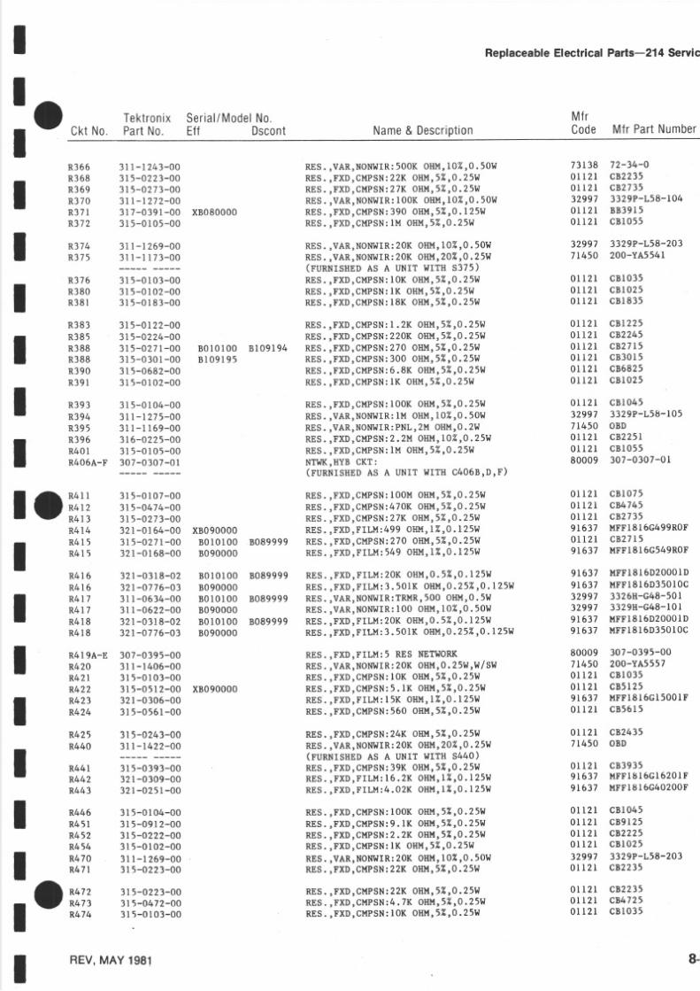
5/14/2018 Tektronix 214 Manual - slidepdf.com
http://slidepdf.com/reader/full/tektronix-214-manual 72/95
I
frck,NoektronixSer ia l /Modelo.
PartNo. Eff Dscont Name Descript ion
ReplaceableEleclricalParts-2l4 Servic
MfrCode MfrPartNumbe
tOi l i3
IIII
II
IIIItII
R366 311-1243-00R368 315-0223-00R369 315 -0273-00R370 3 l l - l 272-00R371 317-0391-00 X8080000R372 315-0105-00
R374 31 -1269-00R375 3 l - t 173 -00
R376 315-0103-00R380 315-0102-00R38 l 315 -0183-00
R383 31 -0122-00R385 315 -0224-00R388 315-0271-00R388 315-0301-00R390 315-0682-00R391 315 -0102-00
R393 315-0104-00R394 31 -1275-00R395 3r - r r69 -00R396 316-0225-00R401 315-0105-00R406A-F 307-0307-01
RES.,VAR,NONII IR:00K OHM,0Z ' 0 . 50WRES.,FXD,CI1PSN:2K OHM, 7 ,0 .25WRES , FXD,CI'|PSN:7K OHM, 'A0 .25tt
RES ,VAR,NONI,IIR:00K OHU, 0U '0 . 50lIRES. ,FXD,C} IPSN:90 OHM, Z,O.L25WRES.,FXD,CMPSN:M OHM, Z,0. 251^ I
RES. VAR,NONI{ IR:20K HM,0U 0.501 IRES.,VAR,NONIJIR:0K OHM, 02,0.25W(runnrsnuD AS A UNIT I{ITH 5375)RES. ,FXD,CMPSN:0K OI IM, 2,0 .25WRES. FXD,CI.{PSN:K OHM, 7"0 .25WRES.,FXD,CMPSN:8K Ot lM, Z ,O 25W
RE S , FX D CMPSN: . 2K OHM, Z O 25WRES.TFXD C}IPSN:20K OHl,t , "4,0 25WRES. FXD,CMPSN:270 HM, "ÄO 25WR E S . , F X D , C M P S N :0 0 O HM , " 1 , 0 . 2 5 WR E S . , F X D , C M P S N :. 8 K O H M , U , 0 .2 5 t IRES. ,FXD,CMPSN:K OI IU, 2 ,0 .25W
RES. FXD,CMPSN:00K OHI' i ,5"40.25WRES.,VAR,NONI ' I IR :M OHM,0Z ' 0 . 50 l IRES.,VAR,NONI' I IRPNL,2U OIIM' . 2I. IR E S . , F X D , C M P S N :. 2 M O H M , 0 U , 0 .2 5 WRES.,FXD,CMPSN:I " I OHM, Z,O 25WNTI.IK,HYBCKT:(runNrsnnD AS A uNrr l l r rH c406B,D,F)
RES. ,FXD,CMPSN:00M OHI ' { ,Z ' 0 .25WRES.,FXD,CUPSN470K O H l t , 2 ,0 . 25 I . IRES. ,FXD,CMPSN:7K OHM, "4,0.25WR E S . , F X D , F I L M : 4 9 9O HM ,Z ' 0 . l 2 5 l lRES. ,FXD,CMPSN:70 OHM' "Ä 0 .25WRES.,FXD,FILM: 49 OHM,Z ,O .125W
RE S , FXD FILM: 20K OHI' { ,05" ÄO. I 25 W
R E S . , F X D , F I L M :. 5 0 I K O H M , 02 5 2 ' 0 . l 2 5 S I
RES.,VAR,NONI,I IRTRMR, 00 OHM, . 5l lRES. ,VAR,NONI{ IR:00 OHI ' i , 02 ,0 . 50W
RES.,FXD,FILM: 0K OHM, .5 " / " , 0 . 25 I {R E S . , F X D , F I L M :. 5 0 I K O HM ,02 5 2 ' 0 . l 2 5 I {
RES.,FXD,FILM:5 RES NETIIORKRES ,VAR,NONIIIR 20K OHM, . zsW,W/SllRES. FXD,CMPSN:0K OHI' I ' Z O.25WRES.,FXD,CMPSN:. lK OHU' Z ' 0 .25WRES.,FXD,FILM: 5K OIIM ' Z ' 0 . I 25 I . IRES. ,FXD,CMPSN:60 OHM, "4,0.25W
RES.,FXD,CMPSN:4K OHM' U '0. 25 I ' lRES.,VAR,NONI{IR:0K OHM, 0Y",0.25W(runnlsHnD AS A UNIT I.IITH S44O)RES. ,FXD,CMPSN:9K OHM, 2 ,0 .25WR E S . , F X D , F I L M :6 .2K O HM , 2 , 0 . I 2 5 I {
R E S . , F X D , F I L M : 4 . 0 2 KO HM ' U , 0 . 2 5 I ' I
RES. ,FXD,CMPSN:00K OHM, 2, 0 . 25 IdRES. ,FXD,CMPSN:. lK OHM' 2 ,O .25WRES.,FXD,CMPSN:. 2K OHI ' { ' 7 ,0 ,25WRES.,FXD,CMPSN:K OHI ' { ,2 0. 25 } f
RES. ,VAR,NONI{ IR:0K OHM,0U ' 0 . 5O IdRES.,FXD,CI.{PSN22K OHü,52,0,25W
RES.,FXD,CI I {PSN22K OHM, U,0. 251{R E S . , F X D , C M P S N4 . 7 K O H U , 5 Z , 0 . 5 t ' lR E S . , F X D , C H P S N :0 K O HM , Z ' 0 . 2 5 t {
73138 72-34-00ll2l cBz?350Il2l c82735
32997 3329P-L58-r040 r l 2 l 8 8 3 9 1 50 1 1 2 1 c B l 0 5 5
32997 3329P-L58-20371450 200-YA554r
0 l 121 cB l 03501121 C810250 l l 2 t c B l 8 3 5
01121 cBr2250Ir2l c822450 l 2 l c B 2 750 l l 2 l c 8 3 0 1 50 l t 2 t c868250 l l 2 l c 8 1 0 2 5
0 l t 2 l cB l 04532997 3329P-L58-r0571450 oBD0lt2l cB225l0 l l 2 I cB l 05580009 307-0307-0I
0 l 121 cB l 0750l l2 l c8474501121 c8273591637 MFFl8l6G499RoF0l l2l cB271591637 MFFl8l6G549RoF
91637 l,{FFl8l6D2000lD91637 MFFt8 l6D350r0C32997 3326H-G48-50132997 3329H-G48-l0l91637 nFFl816D2000lD9t637 UFF18l6D350l0C
80009 307-0395-0071450 200-YA55570 1 1 2 1 c B l 0 3 50 I l 2 l c B 5 I 2 59t637 MFFl8l6Gl500lF0 l l 2 l c B 5 6 l 5
0 l l 2 l c8243571450 oBD
0 r r 2 l c 8 3 9 3 59t637 MFFl8l6Gl620lF
91637 HFFl8l6G40200F
0 l 121 cB l 0450 t l 2 l c B g l 2 50ll2l c822250 l l 2 l c B l 0 2 532997 3329P-L58-2030 l l 2 l c 8 2 2 3 5
0 t l 2 I c B 2 2 3 50 l l 2 l c847250 l t 2 l c B 1 0 3 5
R414R415R4l5
31 -0107-00315-0474-003r5-0273-00321-0164-003 r5 -0271-00321-0168-00
R416 32 r -0318-02
R4l6 321-0776-03R4l7 3 l l -0634-00R4l7 3r -0622-00R418 321-0318-02R4l8 32r-0776-03
R4r9A-E 307-0395-00R420 3l -1406-00R42r 315 -0103-00R422 315-0512-00R423 321-0306-00R424 315-0561-00
R425 315-0243-00R440 3n-1422-00
R446R45lR452R454R470R4 7
3 5-0393-0032 -0309-00
321-0251-00
315-0104-003l 5-09 2-003 l 5-0222-003l 5-0102-003r - l 269-003l 5-0223-00
3 r5 -0223-003l 5-0472-00315-0103-00
B 0 l 0 l 0 0 B 1 0 9 1 9 48 1 0 9 1 9 5
x80900008010100 8089999B090000
B0l0 l00 8089999
80900008010100 808999980900008010100 80899998090000
x8090000
R44lR442
R443
toi' i;REV,MAY 1981 8-

5/14/2018 Tektronix 214 Manual - slidepdf.com
http://slidepdf.com/reader/full/tektronix-214-manual 73/95
ReplaceableElectrlcal Parts-2l4 Servlce
TektronixCktNo. Part o.
Ser ia l /Modelo.Ef f Dscont Name Description
MfrC od e M frPar tNumbe
R475 3 l l - 1269 -00R476 3l l -1 172-OO
RES.,VAR,NONI{IR: 0K OHI' ! , 02,0. 50l lRES ,VAR, NONI{IR PNL,50K OHM, . 2I.l,ttl Sü l(r'unmsunD SA uNrr trrru s476)RES. FXD,CMPSN:33K HU, 2 ,0 .25W
RES.,VAR,NONI{ IR:NL , 00K OHM,0. 5t IRES. ,FXD,CUPSN:3K OHU, Z rO.25W
RES. FXD,CMPSN:68KOIIM, "1r0 25WRES.,FXD,CMPSN220K OHM, U, 0. 25I. IRES , FXD CüPSN: 5 OHI,I, 7"0 .25WRES.,FXDTCMPSNI 5 OHl, l , " /"0 .25WRES.,FXD,FILM: 69K OHI ' { ,Z , 0 . I 25 I . tR E S . , F X D , F I L M :4 9 K O HM , 2 , 0 . l 2 5 l l
RES. FXD,CUPSN:U OHM,5Z,0.25SIRES.,VAR,NONIIIRlU OtlU, 0Z, 0. 5OltRES. ,FXD,CMPSN:70K OIIM, Z,O 25WRES. VAR,NOI{!{ IR:l 't OHM, 02,0.5011RES. ,FXD,CMPSN:70K OHM, Z ,O 25WRES.,FXD,CMPSN:80K OI{M, 2,0.25W
RES. FXD,CMPSN:220 HM, Z O 25WRES , FXD C}IPSN: 20 OHI.{, 'A O 25 WRES.,VAR,NONI' I IR:00K OHM, 02,0. 501{RES. FXD,CMPSN:270K H l . { ,Z ,O 25WRES.,FXD,CMPSN:3K OHI ' { ," 1 ,0 .25WRES.,FXD,CMPSN:. 2M OHM, 02,0. 25 l I
RES. ,FXD,GMPSN:. 7M O HI , I ," 4 ,0 25WRES. FXD,CMPSN:4.K O HU, 2 ,0 . 25WRE S , FXD,CMPSN:5K OHM, 7"O 25WRES.,VAR,NONITIIR:00K OHM,0Z, 0. 50lIRES. FXD,CMPSN:00K O HU, 2 ,0 .25WRES ,FXD CMPSN: 5K OHI'{, 7 ,O 25 W
RES , FXD CMPSN: 0K OHI.{, "4 O 25 WRES. FXD,CMPSN:00 OHM, I ,O ,25 l lRES. ,FXDTCMPSN:47KHM, 2,O.25WRES.TFXD,CIIPSN:. 6K OHI. i , 7,0.25WRE S , FXD,CüPSN: lK OIIM, Z O 25WRES.,FXD,CMPSN:. 5K OHM, 2,0,25W
RES.,FXD,CMPSN:. 5K OHM, 2 ,O .25WR E S . , F X D , C M P S N : 4 .K O H M , Z, O 2 5 WRES.,FXD,CMPSN:7K OHM, 2 ,0 .25WRE S , FX D CMPSN:5K OHM, Z O 25tt
SI, I ITCH, LIDE DPDT,0.5A, I 25VACSI{ITCH,SLIDE DP3T 0 . 5A, I 25VsIdrTcH,sLrDE:Dp3T I{/PLASTTC PLATEDTT-CONTASSY:2 CONTACT(runnrsurD AS A UNIT I{ITH R34O)SI{ITCH,SLIDE DP3T,0 5A, I 25V
SI.IITCH, LIDE: DP3T ltlPLASTIC PLATEDTT-CONTASSY:3 CONTACT
(runnrsHuD As A UNIT II ITH R375)SI . I ITCH,L IDE :DP3T,0 .5A, 25VswITcH,SLIDE : DP3T I{/PLASTIC PLATEDTT-CONTASSY:2 CONTACT(runnrsneDAs A uNrr r{rru n44o)(r'unNrsHsDs A uNrr r{rrH R476)
CKT BOARDASSY:SINGLE SI{EEP(sug ttpl, FoR REPLAcEMENTPARTs)
32997 3329P-r58-20371450 200-YA5540
0 l l 2 l c 8 3 3 3 5
71450 FX94060 l l 2 l c B 3 3 3 5
0 l l 2 l cB 68350lI2l c822450 l r 2 l c B l 5 0 50 l r2 l cB l 50591637 nFF l8 l6c l6902F9t637 MFFl8l6c24902F
0 l l 2 t c B l 0 5 532997 3329P-L58-1050l12 l c8474532997 3329P-L58-1050l l2r cB,47450 l l 2 l c86845
0l t2 l c l j22t50 1 r 2 1 c B l 2 1 532997 3329P-L58-5040l t2 l c827450 l 2 I c833350l12 l cB225r
0 l l 2 r c847550r l2 l c847250 l l 2 l c 8 1 5 3 532997 3329P-L58-1040 l r 2 l c B I 0 4 50 1 1 2 1 C B l 5 3 5
0 t 2 l c820350 l l 2 l c B l 0 t 501121 C847350 t 1 2 1 c 8 5 6 2 50 1 1 2 1 c B l l 3 50 l r 2 r c B I 5 2 5
0 l l 2 l cB t5250l r2r c847250l l2 l c847350 l 2 t c B l 5 3 5
79727 cF l26-002879727 c -128-5-001279727 c -128SPC/80009 2r4-t577-Ol
79727 c -128-5-0012
79727 c - l28SPC/80009 214-1576-0r
79727 c -128-5-001279727 c- l28SPC/80009 2t4-t577-01
80009 670-2676-00
R477
R480R481
R482R485R49lR493R50 lR502
R505R506R508R 5 l 0R5 l1R 5 l 2
R 5 t 3R 5 1 3R 5 l 5R 5 l 6R52rR522
R522R523R524R5 5R526R527
R527R529R530R530
R53 lR532
R535R536R537R54 l
s 2 l 5s305s305s 3 0s340s345
s345s360
s375s405s405s 4 l 0s440s476
3 5-0333-00
3 l - t 1 7 1 - 0 03l 5-0333-00
31 -0683-003 5-0224-00315-0150-003t 5-01 0-0032 -0407-0032 1 0423-00
315-0105-003 1 1 - 1 2 7 5 - 0 03l 5-0474-003r -l 275-OO3 5-0474-003 5-0684-00
315-0221-00315-0121-0031 - r 274 -OO3t 5-0274-003l 5-0333-003l 6-0225-00
3t5-0475-003r5-0472-00315-0153-003l I - l 272-OO3l 5-0104-003l 5-01 3-00
3l 5-0203-003l 5-010100315-0473-003l 5-0562-00
3l 5-01 3-00315-0152-00
315-0 r52 -00315-0472-OO3l 5-0473-00315-0 r53 -00
260-072 -00260-0984-00260-0984-01214-t577-Ol
B 0 l 0 r00 8010331B 0 0332
B0l0r00 8049999
8050000
x8050000
B 0 l 0 l 008010100
8050000xB o 03328 0 1 0 1 0 0Bl08948
8049999X8049999
B108947
B 0 l 0 l 00 80523998052400
s5 0A ls 5 r 0 B (s r r o c{s 5 l 0 D /
260-0984-00 B0l0 l00 8052399
260-0984-01 8052400214-t176-0r
260-0984-00 B0l0 lo0 8052399260-0984-01 80524002r4-t577-OI
-10
670-2676-00 B0l0l00 B059999
REV,MA Y1981

5/14/2018 Tektronix 214 Manual - slidepdf.com
http://slidepdf.com/reader/full/tektronix-214-manual 74/95
I
!o
l oIIIIIIIl o
TektronixSer ia l /ModelNo.PartNo. Eff Dscont
670-2676-Ot 8060000
8010100 B0530868053087 80546598054660
B0l0 l00 8050969
Name Description
CKT BOARDASSY:SINGLE SWEEP(ssn I*{pL FoR REpLAcEMENTpARTs)
MODE EJ,PoTCoRE
XFMR,RF:
MICRoCRCUIT, LI : OUTpUTAIr{PLIFIERMICROCIRCUIT,LI:DUAL opNL AIr{pL& CHANSI {ltIcRocIRcuIT,DI:TRIG e SWEEPAIr{pLMICROCIRCUIT,DI J-K MASTER-SLAVE LIP-FLOP
ELECTRON UBE:CRT,P400, NT SCALE(r'unntsnnD s A uNrr I{rrH L3oo)ELECTRON UBE:CRT,P40O,NT SCALE
(runnrsnnDAs A uNrr l.Irut L3oo)
SEI.{ICOND EVICE ZEMR, 0 . 4I{ 9 . IV ,57,SEMICOND EVICE ZENER,0.4I{ , 0V, lU
Replaceable lectrlcalParte-214Se
Mfr PartNum
80009 670-2676-OL
80009 120-0864-0080009 120-1043-0080009 120- l103-0080009 120-0735-0080009 108-0772-0080009 120-0865-00
80009 120-0865-01
80009 155-0047-0080009 r55-0083-0080009 155-0048-0080009 156-0280-00
80009 154-0695-00
80009 154-0732-00
14433 lN960B80009 152-0514-00
MfrCode
IIII
II
T207T207T207T250T270T280
T280
u 1 0 5u320u370v440
v300
v300
vR228vRz38
I 20-0864-00r 20-1043-00120- l 103-00I 20-0735-00108-0772-00I 20-0865-00
r20-0865-01 8050970
I 55-0047-00r 55-0083-00I 55-0048-00r 56-0280-00
154-0695-00 8010100 8049999
154-0732-00 8050000
I 52-0306-00r 52-0514-00
@ MAY 1980 8-

5/14/2018 Tektronix 214 Manual - slidepdf.com
http://slidepdf.com/reader/full/tektronix-214-manual 75/95

5/14/2018 Tektronix 214 Manual - slidepdf.com
http://slidepdf.com/reader/full/tektronix-214-manual 76/95
I
: tI
IIII
I
Options-2l4 Serv
OPTION NFORMATION
Your instrumentmay be equippedwith one or more options.This sectiondescribeshoseoptionsor
directs he reader o where he option is documented.
OPTION1
Option 1 equips he 214 to r operation ro m a22O o 25 0 V ac48 to 52 Hz power inesource.Option 1partsvalueshat differ from the standard 14 ar e istedhere.A powercord cableassemblyor adaptingoappropiate ower plugs, s includedwith Option 1 instruments. efer o the Maintenance nd Diagramssection f this manual or additional nformation oncerning ption 1.
ELECTRICALPARTSLISTDIFFERENCES OROPTION1
tA3cz0/.c210c212c215
A3c210c212
670-2741-21"283-0279-00285-0933-00285-0933-00283-0279-OO
670-2741-31**285-0935-00285-0935-00
POWER UPPLYCircui tBoardAssemblyOpt ion1)0.001UF,2oo/o,3 V2.OUF,1Oo/o ,4002.0UF,10o/o ,4000.001UF,2Oo/o,3V
POWERSUPPLYCircuitBoardAssembly Option2)4.4 UF, 10o/o,2004. 4 UF 1O"/o,2OO
t o ADDITIONALSTANDARDACCESSORIESOROPTION1
161-0077-01 CABLEASSEMBLY, OWER(Adapts o users lug ype)
*ln someOption 1 instruments,he suffix numberon the boardmay not be marked 21 .
OPTION2
Opt ion2 equ ips he214 or opera t ionrom a 9 0 to 110Vac48to52 Hzpower l inesource.Opt ion2partsvalues hat differ from the standard21 4 are istedhere. Refer o the Maintenance nd Diagramssections f th e manual or additional nformation oncerning ption2.
ELECTRICALPARTSLISTDIFFERENCES OROPTION
IIII
It
!.@
**ln someOption 2 i nstruments,he suffix numberon the boardmay not bemarked 31.

5/14/2018 Tektronix 214 Manual - slidepdf.com
http://slidepdf.com/reader/full/tektronix-214-manual 77/95
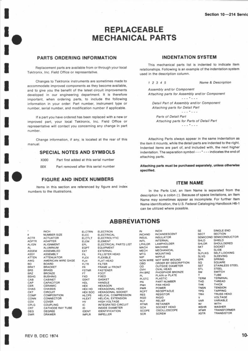
5/14/2018 Tektronix 214 Manual - slidepdf.com
http://slidepdf.com/reader/full/tektronix-214-manual 78/95
I
IIII
It
I
IIII
! r
l o
I
: oI
SE SINGLEEN DSECT SECTIONSEMICONDSEMICONDUCTORSHLD SHIELDSHLDR SHOULDEREDSKT SOCKETSL SLIDESLFLKG SELF.LOCKINGSLVG SLEEVINGSP R SPRINGSO SQUARESST STAINLESSSTEELSTL STEELsw swlrcHT TUBE
TERM TERMINALTH D THREADTH K THIGKTNSN TENSIONTP G TAPPINGTR H TRUSSHEADV VOLTAGEVA R VARIABLEwt wlTHWSHR WASHERXFMR TRANSFORMERXSTR TRANSISTOR
Sectfon 10-214 Servic
REPLACEABLEMECHANICALPARTS
PARTSORDERINGNFORMATION
Replacementartsareavailablero mor through our ocalTektronix, nc. FieldOfficeor representative.
Changeso Tektronix nstruments re sometimesmade oaccommodatemproved omponents s heybecome vailable,and to give you the benefitof the latestcircuit mprovementsdeveloped n our engineeringdepartment. t is thereforeimportant,when ordering parts, to include th e fol lowinginformationn your order: Part number, nstrumentype ornumber, erial umber, ndmodif ication umber f appl icable.
lf a part you haveordered asbeen eplacedwith a neworimprovedpart, your local Tektronix, nc. Field Off ice orrepresentativeil l contactyou concerning ny change n part
number.
Change nformation,f any, s locatedat the rear of thismanual .
SPECIALNOTESAND SYMBOLS
X000 Part irst addedat this serialnumber
00X Part emoved fter his serialnumber
FIGURE ND INDEXNUMBERS
Items in this section are referenced by figure and index
numbers o the i l lustrat ions.
ABBREVIAT!ONS. INCH ELCTRN ELECTRON IN INCH* NUMBERslzE ELEc ELECTRIcAL tNcANo INcANDESCENTACTR ACTUATOR ELCTLT ELECTROLYTIC TNSUL INSULATORADPTR ADAPTER ELEM ELEMENT INTL INTERNAL
ALIGN ALIGNMENT EP t ELECTRICAL ARTSLIST LPHLDR LAMPHOLDER
AL ALUMINUM EOPT EOUTPMENT MACH MACHINEASSEM ASSEMBLED EXT EXTERNAL MECH MECHANICAL
AssY ASSEMBLY FI L FlLLlsrER HEAD MT G MoUNTING
ATTEN ATTENUATOR FLEX FLEXIBLE NI P NIPPLE
AwG AMERICANwlRE GAGE FL H FLAT HEAD No N wlRE Nor wlRE wouND
BD BOARD FLTR FILTER oB D oRDER BY DEscRlPTloN
BRKT BRACKET FR FRAMEOT RONT OO OUTSIDEDIAMETER
BRS BRASS FSTNR FASTENER OVH OVAL HEAD
BRz BRoNzE FT Foor PH BR z PHoSPHoR BRoNzE
BSHG BUSHING FXD FIXEO PL PLAINOTPLATE
cAB cABTNET csKT cAsKET PLsrc PLAsrlcCA P CAPACITOR HD L HANDLE PN PARTNUMBER
cE R CERAMIC HE x HEXAGON PN H PA N HEAD
cHAs cHAssrs HEx HD HExAGoNAL HEAD PwR PowER
cKT clRculr HEx so c HExAGoNAL socKET RcPT REcEPTAcLE
coMp coMposrloN HLcps HELTCAL oMpREsstol l RE S REslsroR
CONN CONNECTOR HLEXT HELICALEXTENSION RG D RIGID
co v covER HV HIGH votrAGE RL F RELIEF
OPLG couPLlNG lc INTEGRATED lRculr RTNR RETAINER
cR T CATHODERAY TUBE lD lNslDE DIAMETER sc H socKET HEAD
DE G DEGREE IDENT IDENTIFICATION SCOPE OSCILLOSCOPE
Dw R DFAWER IMPLR IMPELLER sc R scREw
INDENTATION YSTEM
This mechanical parts list is indented to indicate item
relationships.Following is an example of th e indentation systemused in the descr ipt ioncolumn.
1 2 3 4 5 Name& Description
Assembly nd or ComponentAttachingparts or Assembly ndlor Component
DetailPartof Assembly ndlor ComponentAttachingparts or DetailPart
- - -a - - -
Parts f DetailPartAttachingparts or Partsof DetailPart
- - - - - -
AttachingPartsalwaysappear n the same ndentation sth e tem t mounts, hile hedetailpartsare ndentedo theright.Indented tems are part of, and includedwith, he next higherindentation.heseparationymbol - - * - - - indicateshe endof
attaching arts.
Attachlng parts must be purchasedseparately,unlessolhewlse
specilied.
ITEMNAME
In the Parts List, an ltem Name s separated ro m the
description y a colon(:).Because f space imitations,n ltem
Namemay sometimes ppearas incomplete. or further tem
Name dentification,he U.S.FederalCatalogingandbook 6-1
can be util izedwherePossible.
REVB, DEC 1974 10

5/14/2018 Tektronix 214 Manual - slidepdf.com
http://slidepdf.com/reader/full/tektronix-214-manual 79/95
ReplaceableMechanlcal Parts-2l4 Servlce
Mfr.Code Manufacturer
CROSSNDEX-MFR. ODE UMBEROMANUFACTURER
Address City,State,Zi p
077908530t64281 7 5 1 61 8 1 l
19209
22526230507t785737437 3 8 0 3
76545781 9
79727800098 0 7 1 0
8 3 3 8 s98278
Alt{P, INC .RELIANCE I'IICA CORP.BELDENCORP.MOORE,MAYNARDt. , JR., rNC.WILSIIIRE FOAM PRODUCTS, NC.
GENERALELECTRIC CO., ELECTRONTCCAPACITOR AND BATTERY PRODUCTSDEPT.BATTERY PRODUCTSSEC.BERGELECTRONICS, NC .PRODUCTCOMPONENTS ORPTRI{, CINCH CONNECTORSFISCHER SPECIAL MFC. CO.TEXAS INSTRTUENTS, NC., METALLURGICALII{ATERIALS DIV.MTIELLERELECTRIC CO.TLLINoTS TOOL I{oRKS, rNC.SHAKEPROOF IVISIONC-II INDUSTRIESTEKTRONIX, rNC.ALLEGHET{Y UDLTMSTEEL CORP., A DMSIONoF ALLEGHENYLUDLIIM INDUSTRTES, INC.CENTRAL SCREI{ CO.MALCO A MICRODOTCOII{PANY, NC.CONNECTOR ND CABLE DIVISION
P O BOX 3608342-39TH ST .P . O . B O X 1 3 3 1430 I"IAIN ST.2665 COLUI'IBrAST.
P . O . B O X 1 4YOUK EXPRESSI{AY30 LORRAINEAVE.I5OI MORSEAVENUE446 MORGANST.
34 FOREST STREET1583 EAST 3IST ST.
ST. CHARLESROAD55 0 DAVTSVILLERD.,P O BOX 96P O BO X 50 0
BRACKENRIDGEIORKS, RMR AVE.2530 CRESCENT R.
220 PASADENA VE .
HARRTSBURG,A 17105BROOKLYN, Y 11232RTCHMOND,N 47374STONEHAM, A 02I80TORRANCE,CA 90503
GATNESVTLLE, L 3260INEI.ICUI'{BERLAND,A 17070MT VERNON,NY 10553EL K GROVEVTLLAGE, rL 60007crNcrNNATr, oH 45206
ATTLEBORO, ,tA 02703CLEVELAND,OIt 44114
ELGTN, rL 60120lrARMrNrsrER, PA 18974BEAVERTON,OR 97077
BRACKENRTDGE,A 15014BROADVTEI{, L 60153
souTH PASADENA,CA 91030
0-2 REV F, MAY 198

5/14/2018 Tektronix 214 Manual - slidepdf.com
http://slidepdf.com/reader/full/tektronix-214-manual 80/95
Fig .Index TektronixSer ia l /Modelo.No. PartNo. Eff Dscont O t y 2 3 4 5 Name Description
RepfaceableMechanlcal parts-214 Ser
MfrCode MfrPartNu
tr o
I
IIII
IIl o
l o
r - l 366-1468-01-2 366-1469-01-3 366-1322-05-4 366-1466-02-5 366-1322-02-6 366-1466-01-7 366-1467-03-8 366-1467-02-9 366-1467-01-10 366-1467-04-1 366-1470-01-r 2 348-0285-00
-1 3 2 l l -0213-00-14 2 1 -0 17 0 -0 0-15 3 5 5 -0 1 8 1 -0 0-1 6 2 l l - 0 0 1 9 -0 0
- t7- 1 8- 1 9-2 0-2 1
-2 2-23-24-25-26- 2 7-28-29-3 0- 3 1-32
437-0147-Or2 4- l 850-00348-0254-01334-t859-00
386- l999-00331-0445-00 8055100378-0691,00354-0423-00253-01 3-00337-1458-00386-2185-00200-1400-00214-1805-00200-1469-00200-1470-00200-r467-00
80009 366-1468-0180009 366-1469-0180009 366-1322-0580009 366-1466-0280009
366-t322-0280009 366-1466-0180009 366-1467-0380009 366-1467-0280009 366-1467-0r80009 366-1467-0480009 366-1470-0r80009 348-0285-00
23050 oBD83385 oB D80009 355-0181-0083385 oB D
80009 437-0147-OL80009 214-1850-0080009 348-0254-0180009 334-r859-00
80009 386-1999-0080009 331-0445-0080009 378-0691-0080009 354-0423-00l8 l2r P7 PVC807r0 337-1458-0080009 386-2185-0080009 200-1400-0080009 2r4-1805-0080009 200-1469-0080009 200-1470-0080009 200-1467-00
22526 4735780009 l3l- l L72-oo22526 75060-00722526 4771080009 136-0549-0080009 136-0453-0080009 352-0169-0080009 352-0199-0022526 4743922526 4743922526 4623198278 122-0182-0100779 42869-600779 42869-6o0779 P73-7444l 8 l 2 l MT880009 342-0113-00
80009 200-1238-0119209 418906FD02-
80009 198-3183-0080009 352-0161-0022526 47439l8 l2 l P7 PVC
22526 4735022526 7s060-007
I KNOB:DARKGRAYI KNOB:LIGIiT GRAY1 KNOB:DARKGRAY--POSI KNOB:LT GRAY--POSI KNOB:DARKGRAY--VARI KNOB:LT GRAY--VAR1 KNOB:DARKGRAY--TRGI KNOB:DARKGRAY--IMI KNOB:DARKGRAY--VARI KNOB:DARKGRAY--POSI KNOB:MEDIIIM GRAY1 FLIP-STAND,CAB:1 .94H X 3 .424 I NCI I I d I DE
(ATTACHINGPARTS)I SCREI{,MACIIINE:4-40X 0.312 INCII,PNH NYLON2 SCREI{ ,MACII IMz4-4OX 2.75 INCH,PNH ST L2 STUD,CRYG,HDL:0 .312 I A X 0 .50 I NCI I L ONG2 SCREI{,MACIIINE:4-40X 1. 0 INCII,PNII ST L
* - -I CABTNET,SCOPE:4 . PIN,ALIGNMENT:CIRCUIT BOARD4 . FOOT,CABINET:BLACKRUBBER
UARKER, DENT : STANDARD
SUPPORT, RT :FROMMASK,CRTSCALE:FILTER,LT, CRT:BLUERING, SPRT,CRT:RUBBERTAPE PRESS.SENS O 25 t{ X 0. 125'|THK FOAI.ISIILD,ELECTRONT:CATIIODE RAY TUBESPRT,CRTSII IELD:REARCOVER, LUG:POI{ER CORDsPool,,coRD I{MP:COVER,CORD{RAP:UPPER& LOIIERCOVER,CORD IRAP PROBE UPPERCOVER,CORD {RAP PROBE, OI{ERCK T BOARDASSY:A}IPLIFIER(SEEA2 EPt). CKT BOARDASSY INCLUDES:. TERIT{INAL,PIN:0.365 X 0.25 PII ,BRZ,GOLDPL. CONTACT,ELEC:CKT CARD GROUND. SOCKET,P IN ERM:UlV 0.016-0 .018 DIA P INS. SOCKET,PINTERH:I IORIZ,SQPIN RCPT. SKT,PL.IN ELEK:ELCTRNTUBE,IICONT IT|LEADS
SOCKET,PLUG-IN:I PIN,CRT. . I lLDR,rnnU COnn:2 !{IRE BLACK. CONNBODY,PL,EL:3 I { IRE BLACK. CONNECTOR,TERIi.:22-26At{c,BRS& CU BE GOLD. CONNECTOR,TERIi.t22-26AIdG,BRS&CU BE GOLD. CONNECTOR,TERUz22-26I{G,BRS&CU BE GOLD. CONTACT,ELEC:FOR O.26 AIdc I{IRE. CoNNECTOR,PLUG:CRIüpN,FOR0.4" OD pI N
. CoNNECTOR,PLUG:CRIMPN,FOR0.4rr OD pI N
. CONNECTOR,TERI, I :CRIMPN,FOR0.4rr OD PI N
. TAPE,PRESS. EN S0. l25rrTHK
. INSULATOR,PLATE:CKTCARD,FILMBATTERYASSY: SE E 8T216/RT2I7 EPL). EACH BATTERYASSY INCLUDES:. COVER,BAT ET:PLASTIC,BLACK. BATTERYSET:6V,660 MAll ,sA CELL
. wrRE SET,ELEC:. . HLDR,TERI,iCONN:3 ITIIREBLACK
. CONNECTOR,TER!{.222-26 I{G,BRS&CU BE GOLD
. TAPE,PRESS.SENS0.25 W X 0.l25rrTHK FOAI.{CK T BOARDASSY:POT{ER UPPLY(SEEA3 EPL). TERU,P IN:0 .46 L x 0 .025 SQ.PH BRz cL. socKET,p IN TERM:U/ rd .016-0 .018 DIA P INS
2III
I
IIItII
-33 131-0608-00-3 4 I 3 l - l 1 7 2 -0 0-35 t36-0252-04-36 136-0328-03
I 36-0549-00-37 136-0453-00-38 352-0169-00-39 352-0199-00-40 l3 l -0707-00
1 3 1 -0 7 0 7 -0 0-41 1 3 1 -0 6 2 1 -0 0
I 3 l -0371-00I 3 l - l 1 0 9 -0 0I 3 l - l 109-00I 3 l - 1 1 0 9 -0 2
-42 253-0154-00-43 342-On 3-00
9I
3 1l 2
8 0 1 0 1 0 08054557
80101008 0 t 0 1 0 08040500
x8040500
8054556
8054556x8040499
2737
1 l744I2
-44 200-1238-01-4 5 146-0026-00
I 98-3 83-00-46 352-0161-00-47 I 3 l -0707-00
253-0153-00
I 3 -0589-00t36-0252-04
2I
II3
FTI
4 724
-4 8-49-50
IREVK, MAY1980 1

5/14/2018 Tektronix 214 Manual - slidepdf.com
http://slidepdf.com/reader/full/tektronix-214-manual 81/95
ReplaceableMechanical Parts-2l4 Service
Fig .Index TektronixNo. Par t o .
Ser ia l /Mode lo .Eff Dscont O t y 2 3 4 5 Name Descr ip t ion MfrPartNumber
MfrCode
I - 5 1-5 2- 5 3-5 4-5 5
-56-57-58-5 9-60
-6 1
348-0089-00253-0154-00342-0l 76-001 3 1 - l 1 7 2 -0 0334- l926-00
344-0255-00l 6 l -0078-00I 66-0548-00384- l 198-00
366-1493-00r 3 -0589-00r36-A252-O4I 3t-0608-00I 36-0328-02r3t-0722-00342-0095-00337-t 795-00
-69 2l l -0062-00-70 361-0549-00-71 2 1 0 -0 0 0 1 -0 0-72 2r0-0405-00
-73 407-t285-00
-7 4 2 1 1 -0 0 1 9 -0 0
-75
-76 2 I -0008-00
I Bt I , IPER,PLASTIC:BLACK INYL4 TAPE,PRESS.SENS:0 .25"THK1 INSULATOR,FILM:CIRCUITCARDI CONTACT,ELEC:CKT ARD GROUND2 MARKER,IDENT:DANGER
2 CLIP,ELECTRICAL:FUSEMOUNTI CABLEASSY,PI{R,:2 I^ I IRE'48 INCH LONG
1 FERRULE,RF A :O.144 ID X 0 . 2 2 7 OD,GND4 EXTENSIONSHAFT:STOMGESIüITCI1I CKT BOARDASSY:SINGLE SI{EEP(SEEA4 EPL)
(lrrlctttxc PARTS)211-0125-00 2 SCREI . I ,MACHINEI -72 X 0.25 INCH,PNI I TL
* - -. CKT BOARDASSY INCLUDES:
800091 8 1 1800098000980009
80009t64288000980009
348-0089-00MT8342-0176-00t3 l - t 172-00334-l 926-00
344-0255-00Kctzl27r66-0548-00384-1 98-00
-62-6 3-6 4-6 5-66
-6 7-6 8
I ACTRASSY,PB:4 BUTTON,0 .3 SPACING2 T E R M , P I N : 0 . 4 6L X 0 . 0 2 5 S Q . P HB R Z G L
L2 SOCKET,P lN ERM:U/ I {0 .016-0 .018 DrA PrNs
3 TERMINAL,P IN:0 .365 L X 0 .25 PH'BRZ 'GOLD L
ll SOCKET,PIN TERI'{:IIORIZONTAL6 CONTACT,ELEC:CAlt I.I,CUBE1 INSULATORFILM : SHIELD POLYE TE RI SHIELD,ELEC:STORAGE WITCH
(ertlcnrnc PARTs)I SCREI{ ,MACHINE:2-56 0.312 INCH,RDII ST L
I S P A C E R , S L E E V E : 0 . 1 0 5 X 0 . 0 9 3 I D , A LI I . IASI{ER,OCK: NTL, O 09 2 ID X O. I8. 'OD,ST LI NUT,PLAIN, I IEX . 2-56 X 0 .188 INCH,BRS
* - -I BRACKET,ELECShr:ALUMINUM
(ATTACHINGPARTS)
I SCREI{ ,MACII INE:4-4O 1. 0 INCH,PNH ST L* - -
1 CKT BOARDASSY:INPUT(SEEAI EPL)(lrr lcnrnc PARTS)
3 SCREI{ ,MACHINEz4-40 0.25 INCH,PNH ST L* - -
. CKT BOARDASSY INCLUDES:
. so cK E T , P r N T E R M : U / W . 0 1 6 - 0 . 0 1 8 D r A P r NS
. SKT,PL-IN ELEK:MICROCIRCUIT'14DIP,LOII CLE
. CONTACT,ELEC:0.64 NC H LONG
. SHIELD,ELECATTENUATOR'REAR
. SHIELD,ELEC ATTENUATOR,FRONT(Rrtacntnc PARTs)
I SCREI. I ,MACHINE:-5 6 X 0.875 'OVH'SS T1 T. IASI IER,LOCK:NTL,O.O92 I D X O. IS I IOD,STL
I N U T , P L A I N , H E X . : 2 - 5 6 0 . 1 8 8 I N C I I ' B R S* - -
I SHIELD,ELEC:ATTENUATOR'REARENTER1 SHIELD,ELEC:ATTENUATOR'FRONTENTER1 SHIELD,ELEC ATTENUATORPERIPHERALI CLAUP,LOOP:PRESST,PLASTIC3 HOUSING,SI{ITCII:POLYCARBONATE2 ROTOR,ELECSl{:I{/CONTACTSI ROTOR-CONT SSY:DELRIN,I{/O CONTACTSI DTT-CONTASSY:3 CONTACT2 DTT-CONTASSY:2 CONTACT3 SPRING,DETENT:0 .59D X 0.08 l ' I X 0 .01 THK
3 R O L L E R , D E T E N T : 0 . 1 2 5I A X 0 . 1 2 5 I N C t t L
3 covER'RrRYt'I:crR.Url^äfltfiäpARrs)9 N U T , P L A I N , H E X . : 2 - 5 6 0 ' 1 8 8 I N C H , B R S
* - -
83385 oBD
80009 366-1493-0022526 4735022526 75060-00722526 47357oo779 86282-280009 l3l-0722-0080009 342-0095-0080009 337-r795-00
83385 oBD80009 361-0549-0078189 1202-00-00-0541c73743 2Xl2L57-402
80009 407-r285-00
83385 oBD
83385 oBD
22526 75060-00773803 CS9002-1422526 47359
80009 337-1734-0080009 337-1735-00
83385 oB D78189 1202-00-00-054rc73743 2xr2r57-402
80009 337-1767-OO80009 337-1 68-0080009 337-1766-0080009 343-0213-0080009 380-0244-0080009 401-0127-Or80009 401-0L27-028 0 0 0 9 2 t 4 -1 5 7 6 -0 180009 214-r577-0180009 214-1579-0080009 214-1127-00
80009 200-1232-OO
73743 2Xr2L57-402
-7 7 t36-0252-04-7 8 t36-0269-02-79 l 3 l - 0 7 8 7 -0 0
-8 0 3 3 7 -1 7 3 4 -0 0-8 1 3 3 7 - l7 3 5 -0 0
-82 21 -0091-00-83 210-0001-00-8 4 210-0405-00
-8 5 337-1767-OO-8 6 337-r768-00-87 337-1766-00-88 343-0213-00-8 9 380-0244-00-90 401-01 7-or- 91 4 0 1 -0 1 2 7 -0 2-9 2 2r4-r576-0r-9 3 2r4-t577-0r-9 4 2r4-r579-00-95 2 t4 - t 127-00-96 200-1232-OO
-97 210-0405-00
6 0I
L 2
II
10-4 REVG, MAY 1980

5/14/2018 Tektronix 214 Manual - slidepdf.com
http://slidepdf.com/reader/full/tektronix-214-manual 82/95
Fig.Index Tektronix erial /Modelo.No. Part o. Eff Dscont O t y 1 2 3 4 5 N a m e & D e s c r i P t i o n
ReplaceableMechanicalParts-214 Servic
MfrCode MfrPar tNumb
Ir-
: ot
IttI
IIr o
I
löI
l- 200-2262-00 XB066335-98
. covER,vAR RES:
. RESISTOR:VARIABLE320,R340/3340,R375/5375,
. R395,R420,R44015440,R476,R480(SEE PL FOR PN)
. I .TASHER,NONMETAL:O.625IIDIA,O.OO2IC A
. SI. I ITCH,SLIDEDPDT,0.5A , 125VAC
. S ! ' I ITCH, L IDE DP3T,0 .5A , 125V. S}IITCII, SLIDE DP3T I^I/PLASTIC PLATE
. POST,CONTACT:FORAC K TI P
. I{IRING HARNESS,CIIASSIS
. CONNECTOR,TERM.:22'26 I{G'BRS&CU BE GOLD
. CONNECTOR,TERM:22-26 I{G,BRS& CU BE GOLD
. EYELET,METALLIC:0 .152 D X 0 .245 INCH L'BRS
. EYELET,METALLIC:0 .126 D X 0 .23 I NCI TL 'BRS
. HLDR,TERMCONN:4 [{IRE BLACK
. CONNBODY, L, EL: 5 I' IIRE BLACK
. CONNBODY,PL'EL:6 LIIRE BLACK
. CONNBODY PL, EL: 7 I.IIRE BLACK
. . HLDR,TERMCONN:6 I{IRE BLACKCOVER,SLIDE SI{:MEDIUMGRAY PLASTICCOVER,SLIDE SIrr:DARKGRAY PLASTICCOVER,SLIDE S!{:LIGHT GRAYPLASTICPANEL, IDE: 80009 333-1655-01LAMPASSY:(Srn DS310,DS535EPL)
. EACITLAMP ASSY INCLUDES:
. CONNECTOR,TERM.22-26 AI{G,BRS&CU BE GOLD
. HLDR,TERMCONN:2 hrIRE BLACKITOLDER,ED :0 . 08 6 ID X 0. 20 I OD,PLSTCHOLDER,LED:211214I{IRING IIARNESS SINGLE SI{EEP. CONNECTOR,TERM.22-26 AI.IG,BRS&CU BE GOLD. CONNBODY,PL,EL:3 WIRE BLACKPROBE,VOLTAGE212,48. 55 L,PROBE ONLYPROBEVOLTACE I MEG OHI.{/ MEG OHM,DARKLEAD,TEST I X, LIGI{T GRAYPROBE,VOLTAGE:l. EACH PROBE NCLUDES:. TIP,TEST PROD:RETRACTABLEIOOK
. CABLEASSY,RF:94 OH MCOAX'49.125 LCABLEASSY,RF:. CABLE INCLUDES:
. LEAD,ELECTRICAL STRD, 4 AI.IG, 2 . 5 L. LEAD,ELECTRICAL:PROBE OMMON /CLrc
. WIRE INCLUDES:
. C A B L EN I P , E L E C : 0 . 1 2 5 D - O . 1 7 4 S Q X 0 . 7 5
. COVER,ELEC LIP:YELLOI^MML
. CLIP,ELECTRICAL:ALLIGATOR YP E
. CONTACT,ELEC:O.429NC H LONGBODY,TESTPROD: AR K GRAYBODYASSY,PROBE: lXBODY,TESTPROD:LIGHTGRAYBODYASSY,PROBE:l ME GOHM/I MEG OIIMSILVER
80009 200-2262-00
0853079727
79727797278000980009225262252680009800098000980009800098000980009800098000980009
OB Dcr l 26-0028
c- l 28-s-001G- I 28SPC/I 29-0398-001 7 9 -1 8 4 6 -0 0474394623r2IO-0774-002 1 0 -0 7 7 5 -0 0352-01 2-00352-01 3-00352-01 4-00352-01 5-00352-0202-00200-1480-01200-1480-00200-1480-02
22526 4743980009 352-0169-0080009 352-0360-0080009 352-0360-0180009 179-1992-OO22526 4743980009 352-0199-0080009 010-0262-0180009 010-0262-0580009 010-0262-0280009 0r0-0262-04
80009 0r3-0107-0280009 I 75-1288-0380009 175-1498-01
80009 I 75-0940-0080009 175-0940-01
80009 200-r281-0080009 200-r280-0076545 56896-00071785 318-20-00-00380009 204-0490-0380009 204-0594-0180009 204-0490-0580009 204-0594-02
-99 210-0933-00-100 260-a723-00-101
260-0984-00260-0984-01- r0 2 1 2 9 -0 3 9 8 -0 0-1 0 3 1 7 9 -1 8 4 6 -0 0-ro4 t3 l -0707-00-1 0 5 1 3 1 -0 6 2 1 -0 0-106 2LO-0774-OO-1 0 7 2 1 0 -0 7 7 5 -0 0-1 0 8 3 5 2 -0 1 6 2 -0 0-1 0 9 3 5 2 -0 1 6 3 -0 0
352-01 4-00352-01 5-00
-1 1 0 3 5 2 -0 2 0 2 -0 0-1 I 2 0 0 -1 4 8 0 -0 1- l l2 200-1480-00- l 13 200-1480-02-1 4 3 3 3 -1 6 5 5 -0 1- l l 5
8 0 1 0 1 0 0 0 5 2 3 9 98052400
8 0 1 0 1 0 0 0 5 4 1 3 08 0 5 4 1 t
x80541 1
II
332I
I 45III2III2III2
- 1 1 6 I 3 1 -0 7 0 7 -0 0- I I 7 3 5 2 -0 1 6 9 -0 0
352-0360-00352-0360-01
- l 18 I79-L992-00- l 1 9 I 3 1 -0 7 0 7 -0 0- l 2 0 3 5 2 -0 1 9 9 -0 0
010-0262-0101 -0262-05ot0-0262-02010-0262-04
8010100 0545798054580
B010100 0530048053005B0l0 l00 80530048053005
2I21I6
1 :I
I
IIII
-LzL 013-0107-02-r22 175- r288-03
I 75-1498-08010100B053004B053005
-I23175-0940-00175-0940-01 8010100 053004B053005
- r2 4 2 0 0 -1 2 8 1 -0 0-125 200-1280-00- r26 344-0024-00-I27 2r4-0592-00-1 28 204-0490-03
204-0594-OL-129 204-0490-05
204-0594-02
8 0 1 0 1 0 0B0 l 0 l00B010 008 0 1 0 1 0 0B0 1 0 1 0 08053005801 l 008053005
8053004X8053004X8053004x8053004X8053004
8053004
REV M, MAY 1980 10

5/14/2018 Tektronix 214 Manual - slidepdf.com
http://slidepdf.com/reader/full/tektronix-214-manual 83/95
I
5/14/2018 Tektronix 214 Manual - slidepdf.com
http://slidepdf.com/reader/full/tektronix-214-manual 84/95
oI I oII I I I I I I T I I I I o

5/14/2018 Tektronix 214 Manual - slidepdf.com
http://slidepdf.com/reader/full/tektronix-214-manual 85/95
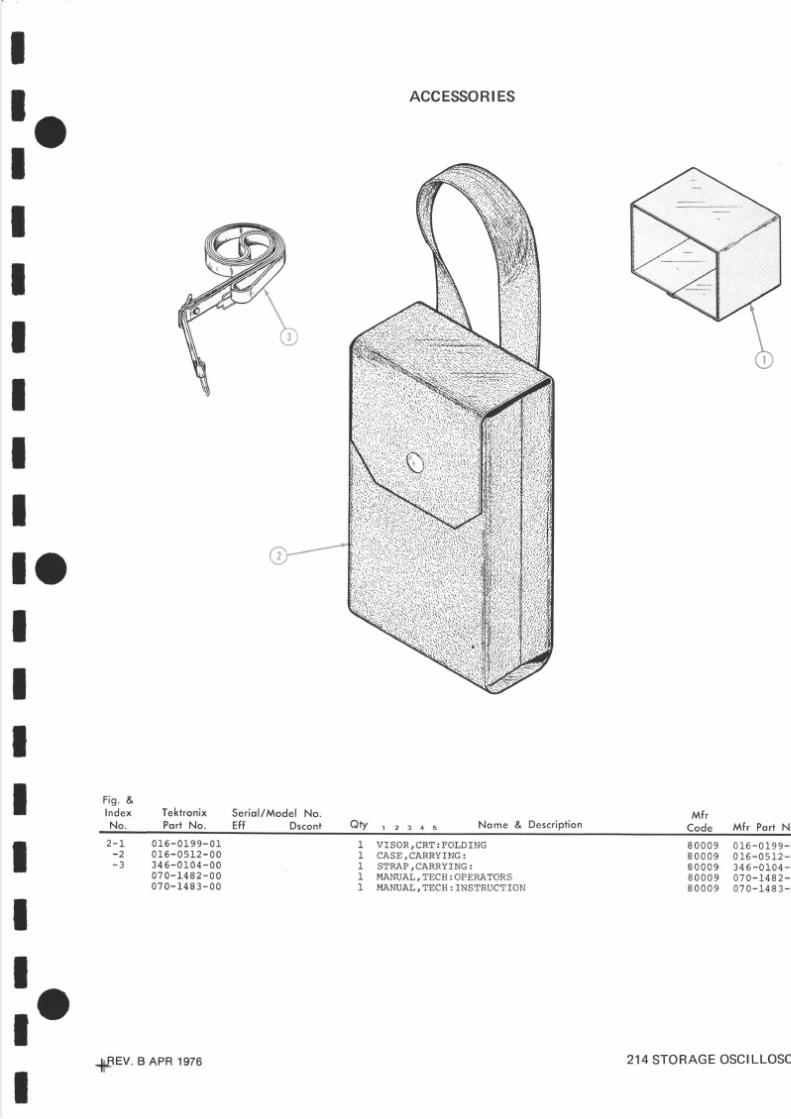
5/14/2018 Tektronix 214 Manual - slidepdf.com
http://slidepdf.com/reader/full/tektronix-214-manual 86/95
I-
r oI
t
IIII
IIl o
Tektronix Ser io l /Model No.Pqrt No . Ef f Dscont
ACCESSORIES
o t y 1 z 3 4 s Nome & Descr ip l ion
I
III Fis .&
I ndex
N o .Mf r
Code Mf r Port Nu
r 2 - L 0 1 6 - 0 1 9 9 - 0 1I - 2 0 1 5 - 0 5 1 2 - 0 0
I- 3 3 4 6 - 0 1 0 4 - 0 0
0 7 - 1 4 8 2 - 0 0
0 7 0 - 1 4 8 3 - 0 0
1 V IS O R,CRT:FO LDING1 CA S E ,CA RRY ING :1 STRAP,CARRYING:1 MANUAL,TECH:OPERATORS
I MANUAL,TECH: INSTRUCTTON
8 0 0 0 9 0 1 6 - 0 1 9 9 -8 0 0 0 9 0 1 6 - 0 5 1 2 -8 0 0 0 9 3 4 6 - 0 1 0 4 -8 0 0 0 9 0 7 0 - 1 4 8 2 -
8 0 0 0 9 0 7 0 - 1 4 8 3 -
I
f...UFEV.B APR 1976lr
214 STORAGEOSCI LOSC

5/14/2018 Tektronix 214 Manual - slidepdf.com
http://slidepdf.com/reader/full/tektronix-214-manual 87/95

5/14/2018 Tektronix 214 Manual - slidepdf.com
http://slidepdf.com/reader/full/tektronix-214-manual 88/95
r oI
tIII
II
I
ItII
tI
t o
MANUAL CHANGE NFORMATION
At Tektronix,we continually trive o keepup with latest lectronic evelopmentsby addingcircuit and component mprovements o ou r instruments ssoon as heyar e developedan d tested.
Sometimes,due to pr int ing and shipping requirements, e can't get thesechanges mmediatelynto pr intedmanuals.Hence, our manualmay containnewchange nformation n fol lowingpages.
A singlechangema yaffectseveral ections.Since he change nformation heetsare carr ied in the manual unt i l a l l changes are permanentlyentered,someduplicationmay occur. f no such changepagesappear ol lowing his page,yourmanual s correct as printed.
SERVICENOTE
Because f theuniversal artsprocurement roblem, om eelectrical arts nyourinstrumentma ybe different rom hosedescribed n he Replaceable lectricalPartsList.The partsusedwi l l n no wayal teror compromisehe performance r rel iabi l i tyof this instrument.They are nstalledwhen necessaryo ensurepromptdelivery oth e customer.Order replacement arts rom the ReplaceableElectricalPartsList.
t o

5/14/2018 Tektronix 214 Manual - slidepdf.com
http://slidepdf.com/reader/full/tektronix-214-manual 89/95
CALIBRATION ESTEQUIPMENT EPLACEMENT
Calibration Test Equipment Chart
This chart compares TM 50 0 product performance to that of older Tektronix equipment. Only thosecharacteristics here significantspecification ifferencesoccur,are listed. n some cases he ne w nstrumentmay not be a total functional replacement. dditional support nstrumentationma y be neededor a change ncalibrationproceduremay be necessary.
DM 501 replaces D1 3
PG 501 replaces1
1083. 0ns nto50Q.
108 10V output ulse1 ns Risetime
PG 502 replaces107
1081 1 1
PG 508 replaces11 4
1 1 5210',
Performanceof replacementequipment s the same or
better han equipmentbeing replaced.
PG 506 replaces10 6
067-0502-01
1904, 1908
1 9 1
067-0532-01
504 replaces067-0532-01
067-06s0-00TG 501 replaces180,
1804
1 8 1184
P G 5 0 2 - 5 V o u t p u tPG 50 2- Risetime ess han
1 ns ; 10 nsPretriggerpulsedelay
1 0 8 - l 0 V o u t p u t111 Riset ime .5 ns:30
to 250 nsPretriggerpulsedelay
106- Positiveand Negative-going trigger outputsignal,50 ns and 1 V;High Ampli tudeoutput,10 0v.
0502-01 Comparator outputcan be alternatelychopped to a refer-ence voltage.
1908 - Ampli tude ange40 mVto 10 V p-p.
0532-01 Frequency ange65 MHz to 500 MHz.
0532-01 Frequencyrange500 MHz.5 MHz
1804 - Triggerpulses1, 10 ,100Hz; 1, 10,and100kHz.Mul t ip letime-markscan begeneratedsimultan-eously.
181 Mult iple ime-marks184 - Separate rigger
pulsesof 1 and 0.1
sec;10 ,1, and 0.1ms; 10 and 1 gs .
2901 Separate riggerpulses, ro m 5 secto 0.1gs . Mult ipletime-marks can begenerated imultan-eously.
NOTE: All TM 500 generator outputs are short-proof. Al l TM 500 plug-ln Instruments require TM 5O&serles Power Module.REVB, JUN 1978
Comparlson of Main Gharacterlstlcs
3. 5ns nto50 O.501 S V ou tpu tpu l s e ;
3. 5ns Risetime
PG 50 6 - Positive-goingtriggeroutput sig-nal at least 1 V;High Ampli tudeout-put, 60 V.
PG 506 - Does not havechopped feature.
SG 503 - Ampli tude ange5 mV to 5.5 V p-p.
SG 503 - Frequencyrange250 kHz to 250 MHz.
SG 504 - Frequency ange
TG 501 - Trigger output-slaved o markeroutput from 5 secthrough 100 ns. On etime-mark can begeneratedat a time.
TG 50 1 - Trigger output-slaved o market
output from 5 secthrough 100 ns. On etime-mark can begeneratedat a time.
TG 501 - Trigger output-slaved o,markeroutput from 5 secthrough 100 ns.One t ime-markca nbe generated ata t ime.

5/14/2018 Tektronix 214 Manual - slidepdf.com
http://slidepdf.com/reader/full/tektronix-214-manual 90/95
I-oI
IIII
IIl o
IIt oI
I
IIII
TelGftrnix MANUALCHANGE NFORMATION6,ür,rrrEDrop(cEuFrrrcE Date: _11-5-80 Change Reference' y142047
product: 214 STORAGESCIIIOSCOPE ERVICE. ManualPartNo.: 070-1483-00
DESCRIPTION
EFI SN 8109195-up
TEXT, REPLACEABLE LECTRICAL ?ARTS, AI{D SCIIEMATC DIAGRÄ!4CIIANGESText
Page 3-5 preceding Recallbratlon After Repair title
ADD:
SeLectable Components. Resistor R388 value is selected fo r a switching rmblankedtrace height of no more than 1.5 dlvislons for each channel- and minimun Lntensltychange when changing sweep speeds from 5 ms to 2 ms. The val-ue of R388 ls selectedfrorn a range of 27O, 300, or 330 ohms as follows:
1. Install a 270 otnrs reslstor for R388, turn the 214 on , se t SEc/DIv to .5 s,
and set IMENSITY to maximum (fully c1ocl,:wlse).
2. The traces !.ril-l- shorr as dots. Set CH I POS to place the CH I dot to the tophorlzontal graticule llne and set CH 2 POS to place the CH 2 dot to the bot-tom horizontal gratlcule Line.
3. Check that no more than 1.5 divisions of unblanked trace extends vertlcallyf rorn each dot.
4. If each unblanked trace exceeds 1.5 vertlcal divisions, turn off the 214'lnstall the next larger size for R388, recheck and.repeat steps 2 through4 until unblanked traces are no more than 1.5 diviolons high whlle main-taini.ng mlnimum lntenslty change when svrltching sweep speed from 5 ms to
2 ms .
Replaceable Elect r ica l Par ts
CIIANGE O:
R388 315-0301-00
L is t
RES. FXD,CIVIPSN:300 IIM (triOUrUAlVAL, SEt)(snr,ecrno FR0M270, 300, or 330 olil{)
Schematic Diagram Change
Diagram 2, Bl c i r cu i t of Q388 in Par t ia l A1 Input Board area.
CIIANGE:
R388 value to SEL
of

5/14/2018 Tektronix 214 Manual - slidepdf.com
http://slidepdf.com/reader/full/tektronix-214-manual 91/95

5/14/2018 Tektronix 214 Manual - slidepdf.com
http://slidepdf.com/reader/full/tektronix-214-manual 92/95

5/14/2018 Tektronix 214 Manual - slidepdf.com
http://slidepdf.com/reader/full/tektronix-214-manual 93/95

5/14/2018 Tektronix 214 Manual - slidepdf.com
http://slidepdf.com/reader/full/tektronix-214-manual 94/95
l oI
IIII
IIl oI
IIII
I
Illl o

5/14/2018 Tektronix 214 Manual - slidepdf.com
http://slidepdf.com/reader/full/tektronix-214-manual 95/95