TEGAM INC. MODEL RT-60B RATIOTRAN · TEGAM INC. MODEL RT-60B RATIOTRAN Instruction Manual PN#...
19
TEGAM INC. MODEL RT-60B RATIOTRAN Instruction Manual PN# RT-60B-901-01 Publication Date: June 2011 REV. B NOTE: This user’s manual was as current as possible when this product was manufactured. However, products are constantly being updated and improved. Because of this, some differences may occur between the description in this manual and the product received.
Transcript of TEGAM INC. MODEL RT-60B RATIOTRAN · TEGAM INC. MODEL RT-60B RATIOTRAN Instruction Manual PN#...

TEGAM INC.
MODEL RT-60B RATIOTRAN
Instruction Manual PN# RT-60B-901-01
Publication Date: June 2011 REV. B
NOTE: This user’s manual was as current as possible when this product was manufactured. However, products are constantly being updated and improved. Because of this, some differences may occur between the description in this manual and the product received.


1-2
Figure 1-2 Dimensions


2-2

3-1. GENERAL. (See figure 3-1.) 3-2. TheRatioTran consists of five transformer windings and five rotary switches. A portion of the input voltage is selected from each winding by the applicable decade switch and these portions are added together to form the output voltage. 3-3. The full input voltage is applied across the first wind-ing which is tapped to provide ten precise voltage divisions. When the first decade switch (X. 1) is turned to a selected position, the lower wiper arm selects a portion of the in-put voltage. The two wiper arms apply reference points
to the second winding which is inductively coupled to the input winding. The lower wiper arm of the X.01 switch selects a 0.01 to 0.1 portion of the input voltage which is added to the voltage selected by the X. 1 switch. The pro-cess continues through the unit until the final and smallest portion of the voltage is selected by the .00001 switch.
3-4. The five transformer windings are included in one transformer. Switching transients are virtually eliminated by resistors which maintain continuity between voltage steps while settings are being changed. Both the input and output circuits are fused.
SECTION III THEORY OF OPERATION
3-1/3-2
4-1. GENERAL. 4-2. Since the RatioTrans are passive devices, a minimum of maintenance is required. With the exception of cleaning switch contacts, no maintenance on a regularly scheduled basis is required. Moving parts are lubricated at the fac-tory and should require no further lubrication.
c. Starting with the voltage control at zero, increase
voltage to 40 vrms.
d. Slowly decrease the voltage to zero. The period of time to reduce the voltage from 40 vrms to zero should be between 10 and 15 seconds.
4-3. SWITCH CONTACTS. 4-4. During calibration intervals, clean switch contacts with a good grade of solvent such as alcohol or acetone. Relubricate switch contacts with a small amount of light Lubricant.
4-5. DEGAUSSING, MODEL RT-60B. 4-6. To degauss the 0.35f units, proceed as follows:
a. Connect a 1K resistor in series with the input con- nection.
b. By means of a variac or other suitable voltage con- trol, apply a 60 Hz signal between the open end of the 1K resistor and the common terminal.
SECTION IV MAINTENANCE
4-1/4-2

SECTION V CALIBRATION
5-1. GENERAL. 5-2. The accuracy of the unit should be maintained for a period of not less than three years, provided that the unit is kept in a normal laboratory environment, has clean, low resistance contacts, and does not suffer injury or insulation damage. 5-3. Under the above conditions, the unit should only require a calibration check every three years. Under more severe conditions, the calibration period must be shortened. 5-4. This section includes two tests: an input impedance test and a simplified ratio accuracy test. Refer to Table 5-1 for a list of test equipment required. 5-5. IMPEDANCE CHECK. 5-6. To check input impedance, proceed as follows: a. Connect unit into test setup as shown in figure 5-1. b. Set input frequency to 400 Hz. c. Adjust voltage source until DVM V1 indicates twice the desired voltage through the unit under test.
d. Adjust decade resistance box until DVM V2 shows equal indications with switch SW-1 in either position A or B. e. Read input impedance from the decade resistance box. The input impedance shall be 400K or more. 5-7. RATIO ACCURACY TEST. 5-8. To test the ratio accuracy, proceed as follows: a. Connect unit into test setup as shown in figure 5-2. b. Set input frequency to 1kHz. c. Apply input voltage of 20 vac as indicated on DVM V1. d. Set RT standard controls for an output reading of 0.0000000. e. Adjust unit under test controls until the null indicator indicates a null. f. Check the ratio indicated by the unit under test against the ratio indicated by the RT standard unit. The two ratios shall agree within the limits listed in table 5-2. g. Repeat steps e through f for each switch position of the RT standard unit (0.11111, 0.22222, etc.). The CT connection shall provide a .50000 output with the same ac- curacy as a .50000 ratio.
Figure 5-1. Impedance Test Setup
5-1

5-2

5-3/5-4
RT-60B
INDEX TO RatioTran ENGINEERING BULLETINS The following Engineering Bulletins cover the theory and applications of RatioTran. BULLETIN NO. SUBJECT
1 Theoretical Analysis of Accuracy of Ratio Transformers
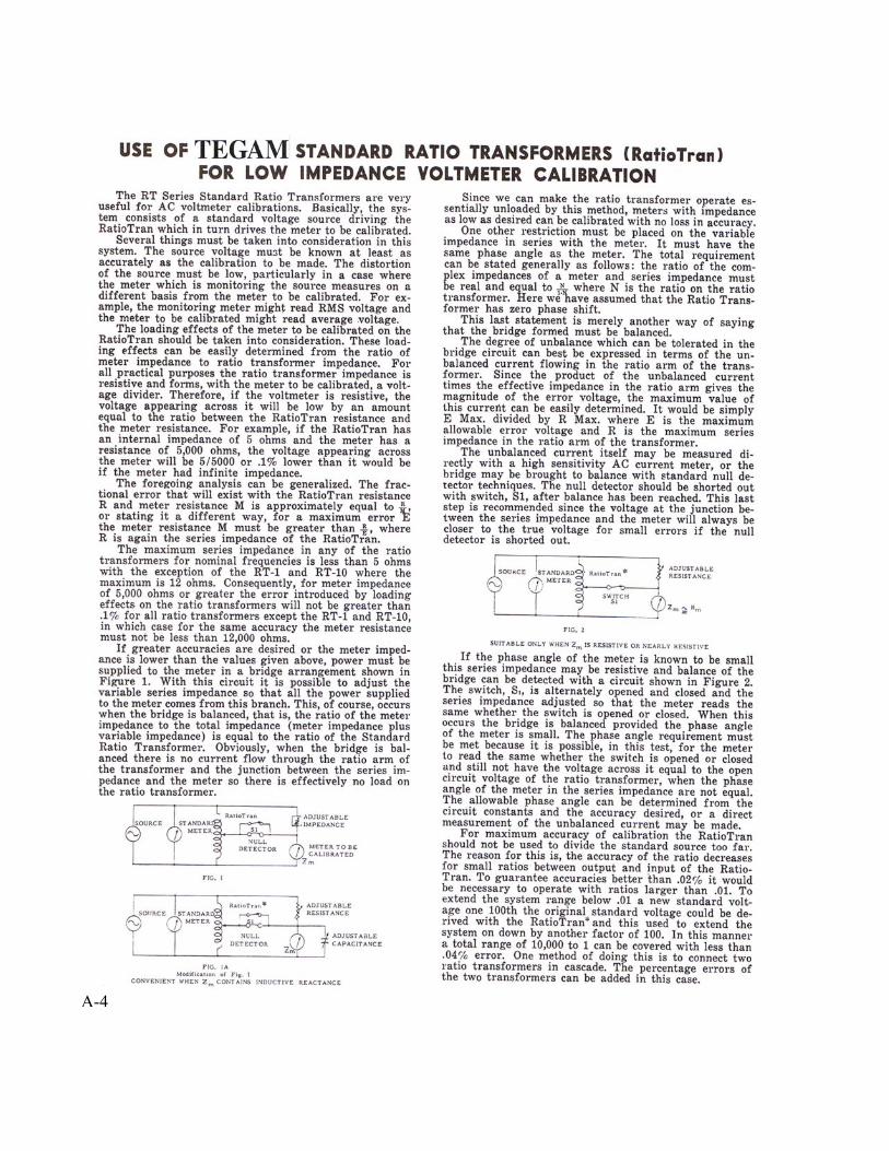
2 Use of Standard Ratio
Transformers for Low Impedance Voltmeter Calibration
3 Accuracy Calculations for
Standard Ratio Transformers
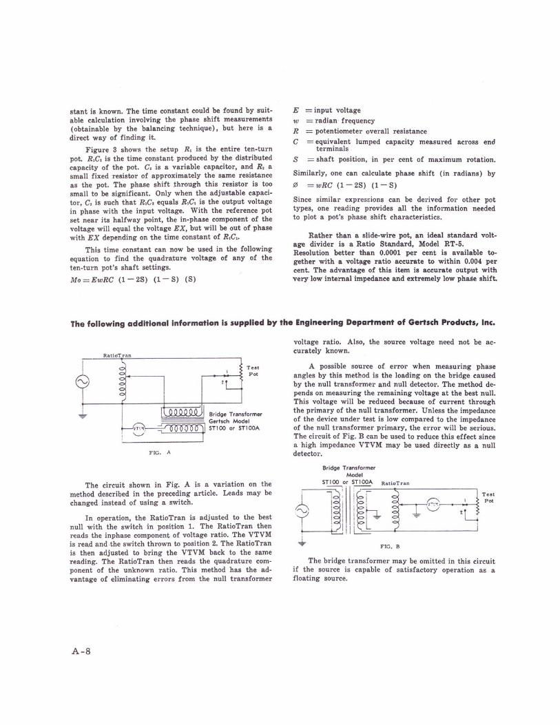
4 Use of RatioTran in Bridge Circuits
5 Measuring Small Phase Angles A-1


A-4


A-6
A-7