Tectonic Plates
43
The American Association of Petroleum Geologists Bulletin V. 63. No 7 (July 1979), P. 1016-1058, 29 Figs.. 1 Table Structural Styles, Their Plate-Tectonic Habitats, and Hydrocarbon Traps In Petroleum Provinces^ T. P. HARDING2 and JAMES D. LOWELL^ Abairact Broadly interrelated assemblages of geo- logic structures constitute the fundamental structural styles of petroleum provinces. These assemblages generally are repeated in regions of similar deforma- tion, and their associated hydrocarbon traps can be anticipated prior to exploration. Styles are differentiat- ed on the basis of basement involvement or detach- ment of sedimentary cover. Basement-involved styles include wrench-fault structural assemblages, compres- sive fault blocks and basement thrusts, extensional fault blocks, and warps. Detached styles are decolle- ment thrust-fold assemblages, detached normal faults ("growth faults" and others), salt structures, and shale structures. These basic styles are related to the larger kinemat- ics of plate tectonics and. In some situations, to partic- ular depositional histories. Most styles have preferred plate-tectonic habitats: (1) wrench faults at transform and convergent plate boundaries; (2) compressive fault blocks and basement thrusts at convergent boundaries, particularly in forelands and erogenic belts; (3) extensional fault blocks at divergent bound- aries in all stages of completion and certain parts of convergent boundaries; (4) basement warps in a vari- ety of plate-interior and boundary settings; (5) decolle- ment thrust-toW belts in trench inner walls and foreland zones of convergent boundaries; (6) detached normal faults, usually in unstable, thick clastic wedges (mostly deltas); (7) salt structures primarily in interior grabens that may evolve to completed divergent boundaries; and (8) shaie structures in regions with thick overpres- sured shale sequences. Important differences in trend arrangements and structural morphologies provide criteria for differentia- tion of styles. These differences also result in different kinds of hydrocartwn traps. Wrench-related structural assemblages are concentrated along throughgoing zones and many have en echelon arrangements. The basic hydrocarbon trap is the en echelon anticline, in places assisted by closure directly against the wrench fault itself. Compressive and extensional fault styles typically have multiple, repeated trends, which com- bine to form zigzag, dogleg, or other grid patterns. Their main trap ^pes are fault closures and drape folds above the block boundaries. Basement warps (domes, arches, etc) are mostly solitary features and commonly provide long-lived positive areas for hydrocarbon con- centration in broadly flexed closures. Most decollement thrust-fold structures are arranged in long, sinuous belts and are repeated in closely spaced, wavellke bands. Effective closures include slightly to moderately disrupted compressive anticlines and lead edges of thrust sheets. Most detached normal faults are lidblc faults that occur In coalescing, cuspate bands parallel with the strike of contemporaneous sed- imentation. Tlieir basic hydrocarbon traps are associ- ated rollover anticlines which are uniquely concentrat- ed along the downthrown sides of major faults. Salt and shale structures are present both as buoyantly ris- ing pillows, domes, ridges, etc, and as highly complex injected features caused by tectonic forces. Strati- graphic factors, such as truncation, wedging, onlap, and unconformity, add to the variety of traps in all styles. In many places the structures of a petroleum prov- ince are either, or both, a gradation between the de- scrit>ed fundamental styles and a mix of several styles. These structures can be further complicated by super- imposition of fundamentally different tectonic environ- ments. Additional modification of structures can result from still other factors inherent in the deformed region or in the particular tectonic event. INTRODUCTION The intent of this paper is to provide an initial framework for better understanding and predicta- bility of structural trends and types of traps in petroleum provinces. Almost all geologic struc- tures, if viewed in enough detail, have unique ge- ometries and histories. On a more regional scale, however, certain general characteristics define broad categories of structures. These characteris- tics are the substance of this report. Our structural classification employs the con- cepts of structural styles and comparative tec- tonics. The style of a particular region describes its dominant structural geometry. Basic styles are ©Copyright 1979. The American Association of Petroleum Geologists. All rights reserved. AAPG grants permission for a single photocopy of this article for research purposes. Other photocopying not allowed by the 1978 Copyright Law is prohibited. For more than one photocopy of this article, users should send request, article identification number (see below), and $3.00 per copy to Copyright Clearance Center, Inc., P. O. Box 765, Schenectady, NY 12301. • Manuscript received, March 8, 1978; accepted, February 26, 1979. 2Exxon Production Research Co., Houston, Texas 77001. ^Consulting geologist. Denver, Colorado 80202. We are indebted to our colleagues past and present at Exxon Production Research Co. Included are W. H. Bucher and E. Cloos (deceased consultants), J. C. Crowell (former consultant), and R. S. Bishop, A. R. Green, F. A. Johnson, Jr., K. H. Hadley, H. R. Hopkins, T. H. Nelson, D. H. Roeder, D. R. Seely, R. C. Shumaker, P. G. Temple, P. R. Vail, R. E. Wilcox, D. A. White, and J. Zimmerman. Many instructive discussions with them greatly increased our exposure to varied structural settings and contributed to the development of concepts. Kaspar Arbenz. A. W. Bally. J. C. Crowell, W. F. Roux. Jr., J. S. Shelton, and G. R. Stude have critically reviewed the manuscript and provided very helpful suggestions. Grateful appreciation is extended to Exxon Production Research Co., for whom this investigation originated, and to Exxon Co., U.S.A.. for their permission to publish. Article Identification Number OI49-1423/79/B007-0001$03.00/0 1016
-
Upload
paul-quispe-solano -
Category
Documents
-
view
7 -
download
1
description
Tectonic Plates
Transcript of Tectonic Plates

The American Association of Petroleum Geologists Bulletin
V. 63. No 7 (July 1979), P. 1016-1058, 29 Figs.. 1 Table
Structural Styles, Their Plate-Tectonic Habitats, and Hydrocarbon Traps In Petroleum Provinces^
T. P. HARDING2 and JAMES D. LOWELL^
Abairact Broadly interrelated assemblages of geologic structures constitute the fundamental structural styles of petroleum provinces. These assemblages generally are repeated in regions of similar deformation, and their associated hydrocarbon traps can be anticipated prior to exploration. Styles are differentiated on the basis of basement involvement or detachment of sedimentary cover. Basement-involved styles include wrench-fault structural assemblages, compressive fault blocks and basement thrusts, extensional fault blocks, and warps. Detached styles are decolle-ment thrust-fold assemblages, detached normal faults ("growth faults" and others), salt structures, and shale structures.
These basic styles are related to the larger kinematics of plate tectonics and. In some situations, to particular depositional histories. Most styles have preferred plate-tectonic habitats: (1) wrench faults at transform and convergent plate boundaries; (2) compressive fault blocks and basement thrusts at convergent boundaries, particularly in forelands and erogenic belts; (3) extensional fault blocks at divergent boundaries in all stages of completion and certain parts of convergent boundaries; (4) basement warps in a variety of plate-interior and boundary settings; (5) decolle-ment thrust-toW belts in trench inner walls and foreland zones of convergent boundaries; (6) detached normal faults, usually in unstable, thick clastic wedges (mostly deltas); (7) salt structures primarily in interior grabens that may evolve to completed divergent boundaries; and (8) shaie structures in regions with thick overpres-sured shale sequences.
Important differences in trend arrangements and structural morphologies provide criteria for differentiation of styles. These differences also result in different kinds of hydrocartwn traps. Wrench-related structural assemblages are concentrated along throughgoing zones and many have en echelon arrangements. The basic hydrocarbon trap is the en echelon anticline, in places assisted by closure directly against the wrench fault itself. Compressive and extensional fault styles typically have multiple, repeated trends, which combine to form zigzag, dogleg, or other grid patterns. Their main trap ^pes are fault closures and drape folds above the block boundaries. Basement warps (domes, arches, etc) are mostly solitary features and commonly provide long-lived positive areas for hydrocarbon concentration in broadly flexed closures.
Most decollement thrust-fold structures are arranged in long, sinuous belts and are repeated in closely spaced, wavellke bands. Effective closures include slightly to moderately disrupted compressive anticlines and lead edges of thrust sheets. Most detached normal faults are lidblc faults that occur In coalescing, cuspate bands parallel with the strike of contemporaneous sedimentation. Tlieir basic hydrocarbon traps are associated rollover anticlines which are uniquely concentrated along the downthrown sides of major faults. Salt and shale structures are present both as buoyantly rising pillows, domes, ridges, etc, and as highly complex injected features caused by tectonic forces. Strati-graphic factors, such as truncation, wedging, onlap,
and unconformity, add to the variety of traps in all styles.
In many places the structures of a petroleum province are either, or both, a gradation between the de-scrit>ed fundamental styles and a mix of several styles. These structures can be further complicated by super-imposition of fundamentally different tectonic environments. Additional modification of structures can result from still other factors inherent in the deformed region or in the particular tectonic event.
INTRODUCTION The intent of this paper is to provide an initial
framework for better understanding and predictability of structural trends and types of traps in petroleum provinces. Almost all geologic structures, if viewed in enough detail, have unique geometries and histories. On a more regional scale, however, certain general characteristics define broad categories of structures. These characteristics are the substance of this report.
Our structural classification employs the concepts of structural styles and comparative tectonics. The style of a particular region describes its dominant structural geometry. Basic styles are
©Copyright 1979. The American Association of Petroleum Geologists. All rights reserved.
AAPG grants permission for a single photocopy of this article for research purposes. Other photocopying not allowed by the 1978 Copyright Law is prohibited. For more than one photocopy of this article, users should send request, article identification number (see below), and $3.00 per copy to Copyright Clearance Center, Inc., P. O. Box 765, Schenectady, NY 12301.
• Manuscript received, March 8, 1978; accepted, February 26, 1979.
2Exxon Production Research Co., Houston, Texas 77001.
^Consulting geologist. Denver, Colorado 80202. We are indebted to our colleagues past and present at Exxon
Production Research Co. Included are W. H. Bucher and E. Cloos (deceased consultants), J. C. Crowell (former consultant), and R. S. Bishop, A. R. Green, F. A. Johnson, Jr., K. H. Hadley, H. R. Hopkins, T. H. Nelson, D. H. Roeder, D. R. Seely, R. C. Shumaker, P. G. Temple, P. R. Vail, R. E. Wilcox, D. A. White, and J. Zimmerman. Many instructive discussions with them greatly increased our exposure to varied structural settings and contributed to the development of concepts. Kaspar Arbenz. A. W. Bally. J. C. Crowell, W. F. Roux. Jr., J. S. Shelton, and G. R. Stude have critically reviewed the manuscript and provided very helpful suggestions. Grateful appreciation is extended to Exxon Production Research Co., for whom this investigation originated, and to Exxon Co., U.S.A.. for their permission to publish.
Article Identification Number OI49-1423/79/B007-0001$03.00/0
1016

structural Styles In Petroleum Provinces 1017
defined by an assemblage of tectonically related elements and their spatial arrangement. Although styles are often modified by local rock differences, such as ductility contrasts and preexisting fabric, and tectonic events, including intensity, duration, and timing, the principal style or styles are usually discernible. For basic style definitions, morphologic types, essential repeatable characteristics, and general trend arrangements are emphasized rather than number of structures present in a specific region, their geographic localities, or particular histories. The concept of comparative tectonics involves the use of basic styles, well documented in one area, as guides for structural interpretation of a lesser known but similarly deformed area.
Several structural classifications have been made (Badgley, 1965, p. 50-97). None, however, have dealt directly with subsurface structures and associated hydrocarbon traps in sedimentary basins. Moreover, recent data in support of large-scale lithospheric plate movement show some earlier classifications that featured only a limited number of deformational mechanisms (e.g., the "verticalist" approach of Beloussov, 1959) are incomplete. Plate tectonics has also provided a unified concept of deformational processes and tectonic habitats to which structures can be related. Finally, deep-penetration reflection seismic surveys processed with modern techniques have revealed subsurface structures, such as detached normal faults ("growth faults"), that were poorly known at the time of past classifications. Modern seismic data have also resolved critical older tectonic controversies, demonstrating conclusively, for example, the validity of regional detachment or decoUement in thrust-fold belts (Bally et al, 1966).
In this paper we categorize structural styles in petroleum provinces and discuss key characteristics for their differentiation. Each style is treated as to common plate-tectonic settings, typical structural patterns and morphologies, critical differences from other styles, and associated hydrocarbon traps. Last, factors influencing variations in style expression and occurrence are discussed.
STRUCTURAL STYLES IN PETROLEUM PROVINCES
Classification of Structural Styles
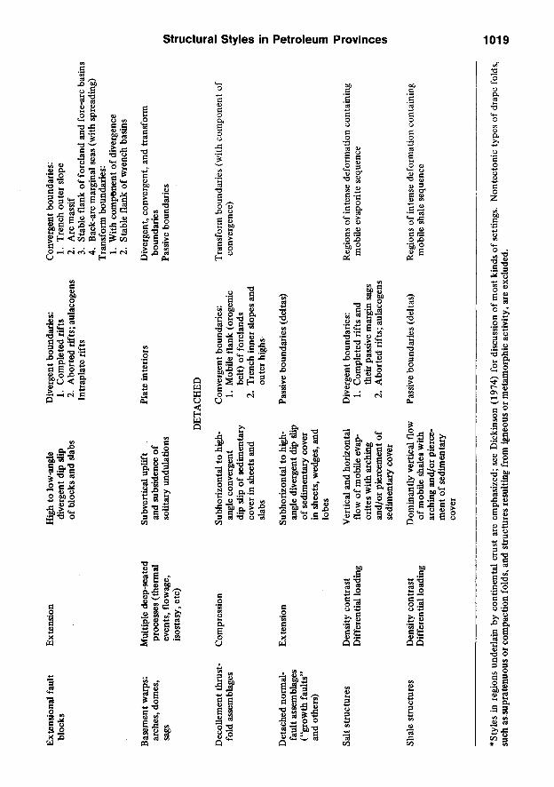
Our classification of structural styles is based primarily on the involvement or noninvolvement of basement in the observed structures. Additional criteria are inferred deformational force and mode of tectonic transport inferred from strain features of the structures (Table 1). Although
basement can exhibit widely different competence and mechanical behavior, in petroleum provinces it is usually rigid crystaUine igneous or metamorphic rock. The degree of basement involvement is critical to petroleum exploration, for it indicates not only how structures propagated, but, qualitatively, how much of the sedimentary section is in a trap configuration (Fig. 1).
Structural styles are initially treated separately as discrete "end members" to facilitate description and to emphasize their distinctive aspects. Styles apply in scale to trends of tectonically interrelated, contemporaneous structures, but consideration is also given to the components common to single features. Each style has provided hydrocarbon traps (Fig. 1).
Identification of Styles
Identifying structural styles is one of the critical tasks in petroleum exploration and is often difficult because a single characteristic seldom is unique to one structural assemblage, and identification must be made early with few data. Identification depends mostly on (1) recognition of key structural elements such as en echelon folds and faults, trap-door blocks, rollover anticlines, etc; (2) critical differences in local trend arrangements; and (3) gross regional patterns of structures. Following is a resume of the most common distinguishing characteristics:
Drag fold—Fold formed by drag of sedimentary rocks along a fault.
Drape (forced) fold—Fold formed in sedimentary layers by a forcing member from below, usually a basement fault block.
En echelon—Consistently overlapped structures aligned parallel with one another but oblique to the zone of deformation in which they occur.
Intersecting or grid—Structures repeated in multiple alignments crisscrossing over broad areas (Fig. 12); these can combine to form zigzag or dogleg (Fig. 11, index map) and clustered features.
Irregularly clustered—Concentrations of structures that lack consistent spatial arrangements.
Parallel—Similar elements in parallel alignment. In some places parallel trends may be repeated in closely spaced, wavelike bands, constituting belts whose sinuosity delimits salients and reentrants (Fig. 3).
Relay—Inconsistently overlapped elements ahgned parallel with one another and with the zone of deformation in which they occur.
Solitary—Isolated, singular features generally not aligned with other structures of similar characteristics.
Trap-door blocks—Blocks formed by intersec-

1018 T. P. Harding and James D. Lowell
tion of two faults with maximum relative uplift at or near the point of intersection.
Zonal—Structures in a discrete, elongate, linear trend. Local trends can be longitudinal (parallel), obhque, or transverse to the larger or dominant structural features of an area.
BASEMENT-INVOLVED STRUCTURES
Wrench-Fault Assemblages
Transform plate boundaries are the primary environment of wrench-fault structural assemblages, but divergent and convergent boundaries are also very important habitats (Table 1; Fig. 2). On transform boundaries the movement between lithospheric plates results in a side-by-side motion in concert with the strike-slip kinematics of the style itself. Strike slip in this example is commonly distributed throughout a set of parallel faults (Fig. 2A), or it can be concentrated on a single master fault (Fig. 2B). Parallel transform faults are also present at divergent boundaries, where they offset spreading axes. Where transforms intersect divergent continental margins, they can deUmit subbasins with different depositional histories, as along the West African and East Greenland shelves (Lehner and DeRuiter, 1977; Surlyk, 1977).
Master wrench faults also develop subparallel with convergent plate boundaries (Fig. 2C) and are attributed to obliquity of plate encroachment (Fitch, 1972). These are longitudinal wrench faults (a term suggested by D. R. Seely, personal commun., 1971) and typically occupy axial positions in orogenic belts or magmatic arcs (e.g., Zagros Main fault. Figs. 3, 4).
Strike-slip faults trending at an angle to the alignment of the convergent plate boundary are termed "oblique wrench faults." They are present in orogenic belts (Fig. 2D) and forelands, and many seem to have patterns and senses of displacement that conform to conjugate shear sets. Foreland wrench faults generally have smaller displacements and less widely distributed associated structures than those of either the transform or longitudinal type. The region north of the Himalayas may contain notable exceptions (Tap-ponnier and Molnar, 1976).
Continental lithospheric segments of divergent margins not near oceanic crustal joins and intra-plate graben systems incorporate wrench faulting less commonly. Intraplate regions appear to be the least common habitat. In North America, the known midplate wrench faults mostly have small displacements, plus Umited associated structures which commonly have a fault (rather than fold) response to the wrench tectonics. The Cottage
J3 eg
S •a
•a 3
3 i i
1
I i
o
O eg Q S
o 3
S rt a> g ^ ^ (•H
^ "̂ .2 "i
£?S £ a C . . .
e 3
o "a > S
H z w w <
111 3 3 2
3 O U
II
e o p. B o
I -I
If T3 13 3 ^ O a>
XI O
a o
2
II £?S
O rf U
lit o H a
o o 3 u
3 SS"^ g o o S
o
I ^ S
Ext
ensi
onal
fau
lt bl
ocks
E
xten
sion
H
igh
to lo
w-a
ngle
di
verg
ent
dip
slip
of
blo
cks
and
dabs
Div
erge
nt b
ound
arie
s:
1. C
ompl
eted
rif
ts
2. A
bort
ed r
ifts
; aul
acog
ens
Intr
apla
te r
ifts
Con
verg
ent
boun
dari
es:
1. T
renc
h ou
ter
slop
e 2.
Arc
mas
sif
3.
Stab
le f
lank
of
fore
land
and
for
e-ar
c ba
sins
4.
Bac
k-ar
c m
argi
nal
seas
(with
spr
eadi
ng)
Tra
nsfo
rm b
ound
arie
s:
1. W
ith c
ompo
nent
of
dive
rgen
ce
2. S
tabl
e fla
nk o
f w
renc
h ba
sins
Bas
emen
t war
ps:
arch
es, d
omes
.
Dec
olle
men
t th
rust
-fo
ld a
ssem
blag
es
Det
ache
d no
rmal
-fa
ult
asse
mbl
ages
("
grow
th f
ault
s"
and
othe
rs)
Mul
tiple
dee
p-se
ated
pr
oces
ses
(the
rmal
ev
ents
, fl
owag
e,
isos
tasy
, etc
)
Com
pres
sion
Ext
ensi
on
Subv
ertic
al u
plif
t an
d su
bsid
ence
of
solit
ary
undu
latio
ns
Plat
e in
teri
ors
DET
AC
HED
Subh
oriz
onta
l to
hig
h-an
gle
conv
erge
nt
dip
slip
of
sedi
men
tary
co
ver
in s
heet
s an
d sl
abs
Subh
oriz
onta
l to
hig
h-an
gle
dive
rgen
t di
p sl
ip
of s
edim
enta
ry c
over
in
she
ets,
wed
ges,
and
lo
bes
Con
verg
ent
boun
dari
es:
1. M
obile
flan
k (o
roge
nic
belt)
of
fore
land
s 2.
Tre
nch
inne
r sl
opes
and
ou
ter
high
s
Pass
ive
boun
dari
es (
delta
s)
Div
erge
nt, c
onve
rgen
t, an
d tr
ansf
orm
bo
unda
ries
Pa
ssiv
e bo
unda
ries
Tra
nsfo
rm b
ound
arie
s (w
ith c
ompo
nent
of
conv
erge
nce)
c £"
(/>
*̂
•<_ (D
5'
•D a o.
(D
C 3
Salt
stru
ctur
es
Den
sity
con
tras
t D
iffer
entia
l lo
adin
g V
ertic
al a
nd h
oriz
onta
l flo
w o
f m
obile
eva
p-or
ites
with
arc
hing
an
d/or
pie
rcem
ent
of
sedi
men
tary
cov
er
Div
erge
nt b
ound
arie
s:
1. C
ompl
eted
rif
ts a
nd
thei
r pa
ssiv
e m
argi
n sa
gs
2. A
bort
ed r
ifts
; aul
acog
ens
Reg
ions
of
inte
nse
defo
rmat
ion
cont
aini
ng
mob
ile e
vapo
rite
seq
uenc
e O
< 5'
o
at
Shal
e st
ruct
ures
D
ensi
ty c
ontr
ast
Diff
eren
tial
load
ing
Dom
inan
tly v
ertic
al f
low
of
mob
ile s
hale
s w
ith
arch
ing
and/
or p
ierc
em
ent
of s
edim
enta
ry
cove
r
Pass
ive
boun
dari
es (
delta
s)
Reg
ions
of
inte
nse
defo
rmat
ion
cont
aini
ng
mob
ile s
hale
seq
uenc
e
*Sty
les
in r
egio
ns u
nder
lain
by
cont
inen
tal
crus
t ar
e em
phas
ized
; se
e D
icki
nson
(19
74)
for
disc
ussi
on o
f m
ost k
inds
of
setti
ngs.
Non
tect
onic
typ
es o
f dr
ape
fold
s,
2 su
ch a
s su
prat
enuo
us o
r co
mpa
ctio
n fo
lds,
and
str
uctu
res
resu
lting
fro
m i
gneo
us o
r m
etam
orph
ic a
ctiv
ity, a
re e
xclu
ded.
;o

1020 T. P. Harding and James D. Lowell
WRENCH FAULT ARCHES, DOMES
EXTENSIONAL BLOCK COMPRESSIVE BLOCK
THRUST-FOLD BELT
FIG. 1—Schematic diagrams of hydrocarbon traps (black areas) most commonly associated with structural styles of sedimentary basins. Purely stratigraphic type traps and traps associated with basement thrusts are omitted. Salt-related closures modified after Halbouty (1967, Fig. 6). BC, basement complex; T, displacement toward viewer; A,
away from viewer.
Grove fault of the southern Illinois basin appears to be a characteristic example (Wilcox et al, 1973). Not all midplate wrench faults developed this way, however. The Rough Creek fault zone, also of the Illinois basin area, has associated en echelon folds and other compressive features suggesting a moderately large right-lateral displacement.
The structures associated with wrench faults (Fig. 5) are more diverse than those of any other
style and include most elements that are fundamental to other styles. Wrench assemblages have both compressional and extensional features (Harding, 1973), or are dominated by compressional (Harland, 1971; Lowell, 1972; Harding, 1974), or extensional structures (Harland, 1971; Harding, 1974). These three substyles, side-by-side, convergent, and divergent wrenching, result from the configuration of the laterally moving blocks, or from the orientations of their bound-

structural Styles in Petroleum Provinces 1021
aries relative to regional plate motion, or both (Wilcox et al, 1973).
The structural patterns of a single wrench zone show much repetition. Tectonic relations between several wrench faults, however, are much less consistent. Wrenches develop as singular, major displacement zones more commonly than other kinds of faults, such as thrusts, block faults, or detached normal faults, which tend to occur in sets. The diversity of several documented wrench zones (Fig. 2) demonstrates that their occurrence cannot be adequately explained by any single, unifying scheme. We thus differ, for example, with Moody and Hill's (1956) and Moody's
(1973) universal conjugate wrench sets. They considered such sets to be the result of pervasive meridional and equatorial compression, with faults formed at 30° angles to maximum principal compressive stress. Their approach disregards the kinematic and structural differences between different types of plate boundaries and tectonic settings. Their views are inconsistent with relations demonstrated by earthquake focal mechanisms; moreover, plate rotations would disrupt the orientations of any such global fault system.
The wide variety of features included in wrench-fault assemblages has resulted in confusion with other styles. Where direct offset data
(after Moore and Buffington. 196B)
MEXICO
KILOMETERS (after Vroman, 19671
B. DEAD SEA ASYMMETRIC MASTER TRANSFORM SYSTEM
Established or Inferred Plate Motion
0 100 200
(after FitOi, 19721
(simplified from Stocklin and Nabavi, 1973)
C. WESTERN INDONESIA LONGITUDINAL WRENCH FAULTS D. OBLIQUE WRENCH FAULTS.SOUTHEASTERN IRAN
FIG. 2—Wrench "set" examples. A, from transform plate boundary; strike slip occurs on parallel fault set. B, example from transform plate boundary; short, right-lateral antithetic strike-slip faults intersect single, main displacement zone at various oblique an^es. C, example from convergent plate boundary; aligned left- and right-lateral faults presumably owe their opposing displacements to differences in sense of obliquity of plate encroachment that results from bend of plate boundary, D, example from convergent plate boundary; strike-slip displace
ments may have developed analogous to conjugate shears. Adjoins right margin of Figure 3.

1022 T. P. Harding and James D. Lowell
are lacking, two characteristics provide a basis for initial distinction of wrench faults. The oblique resolution of stresses along a finite, throughgoing tectonic boundary (Fig. 5, center) commonly causes structures (1) to be arranged en echelon and (2) to be confined to a relatively narrow, persistent, linear zone.
In profile view, some wrench faults have a characteristic seismic signature termed a "flower
structure" (R. F. Gregory, personal commun., 1970). It is expressed as an upward-spreading fault zone, whose elements usually have reverse separations (Fig. 6); the spreading fault system need not be symmetrical; half-flowers are also known (Lowell, 1972). Development of flower structures is enhanced where strike slip is accompanied by components of convergence (Lowell, 1972) and where the rocks are highly mobile. Syl-
FIG. 3—Zagros orogenic belt, Iran. Frontal or external folds are considered to be detached and probably thrust in part. Basement-involved thrusts are present adjacent to Zagros Main fault, which has a late-stage component of right-lateral strike slip. Buoyantly and tectonically injected salt structures also contribute to mix of structural styles.
Generalized from Stocklin and Nabavi (1973).

structural Styles in Petroleum Provinces 1023
vester and Smith (1976) have documented surface examples along the San Andreas fault in Mecca Hills, Cahfornia, and have described their genesis.
Flower-structure reversals can be differentiated from those in other structural styles by recognizing fault displacements directly below the reversal that indicate a high-angle fault stem involving basement (Fig. 6). "Negative" flower structures
have also been observed and consist of shallow sags overlying upward-spreading strike-slip faults with normal separations.
A great variety of hydrocarbon traps (Fig. 1) occurs with the wrench-fault substyles. By far the most prolific have been those associated with en echelon folds. En echelon normal fault blocks, subthrust bed terminations, and flower structures have also been effective traps. Closure types and
PERSIAN
9 ExpoMd SaR MasM*
O Burlad SaH D a m n
* VolcaniMs!( Mostly NaogaiM ami Quatamary)
OH and Gas FlaMs
Ralativ* Plats Motion
INTRUSIVE8
\i,»]i'\ Mssoioic
^ S ^ Pfscambrtan
METAMORPHICS
^ijif^ Masozolc
VOLCANKS
^Maaozolc
^ T a r t i a r y
[<afy'.| Waogsns-Oiiatatnanr
|io>^|Ophlolltss

1024 T. P. Harding and James D. Lowell
CENTRAL IRAN
NNE
Zagros Main Fault
Qum -r , Qt. Vole. T. . . OR/ DEZFUL STRUCTURAL EMBAYMENT SSW
5^3-0
50
NO VERTICAL EXAGGERATION
SEDIMENTS
A r a b i a n S h i e l d
(Modified After Gansser, 1974)
-LsOhm
Km • / • - / • v
TERTIARY MESOZOIC PALEOZOIC
FIG. 4—Generalized cross section of Zagros orogenic belt; extends southwest from city of Qum (see Fig. 3). See Figure 3 for explanation of symbols.
A. INCIPIENT B. EAHLY STAGE WRENCH ZONE WRENCH ZONE
I POTENTIAL PROSPECT CLOSURE
C. INTERMEDIATE STAGE WRENCH ZONE
APPROXIMATE RELATIVE PLATE MOTION
D. MATURE STAGE WRENCH ZONE
BASIN MARGIN SEDIMENTARY WEDGES
-Slip ^/^ Normal Pv. Thrust or Reverse
FIG. S—Schematic diagram of structural assemblage associated with major wrench fault and stages in evolution that cause changes in hydrocarbon trapping; modeled after California examples (discussed in Harding, 1974). Arrows C, E represent compressive and extensional vectors, respectively, that arise from coupling motion between
adjacent plates.

sour
mes
T N
OR
WeA
ST
-0
.0
C9
•D
<D
O.
(D
C 3 TJ
O o
(D
«>
FIG
. 6—
Mig
rate
d se
ism
ic p
rofil
e ac
ross
wre
nch-
faul
t zo
ne i
n A
rdm
ore
basi
n of
Okl
ahom
a de
mon
stra
ting
flow
er-s
truct
ure
geom
etry
(ad
apte
d fro
m u
nmig
rate
d in
terp
reta
tion
by R
. F. G
rego
ry a
nd E
. C. L
ooka
baug
h, 1
973)
. Msp
, Mis
siss
ippi
an S
prin
ger,
Msy
, Mis
siss
ippi
an S
ycam
ore,
and
Ooc
, Ord
ovic
ian
Oil
Cre
ek r
efle
ctor
s.
T, d
ispl
acem
ent
tow
ard
view
er, A
aw
ay f
rom
vie
wer
.
Ul

1026 T. P. Harding and James D. Lowell
changes in the prospective fairway that develop with increased strike slip have been described previously (Fig. 5; Harding, 1974, 1976).
Compressive Fault Blocks and Basement Thrusts
Compressive fault blocks (Fig. 7) and basement thrusts preferentially occur on convergent-plate boundaries. The former are typically more areally restricted, being confined mostly to forelands, whereas the latter are found in forelands, orogenic belts, and landward walls of oceanic trenches (Table 1). Compressive blocks are discussed first, then basement thrusts with which compressive blocks seem to be transitional in foreland settings, and finally, basement thrusts in settings other than forelands.
Forelands are developed in two convergent-margin positions, back-arc and peripheral (adapt
ed from Dickinson, 1974). Back-arc forelands lie between the magmatic-volcanic arc and the era-ton and commonly have thrust-fold belts directed toward the plate interior or craton ("Andean" or "Cordilleran" type, Dewey and Bird, 1970). Peripheral forelands develop with continental collision and have thrust-fold belts lying between the magmatic-volcanic arc and the former trench ("collision" or "Himalayan" type. Figs. 3, 4). Folds and thrusts in this example are directed toward the plate boundary or position of the earlier trench.
Compressive blocks are best known from the Laramide back-arc foreland of Wyoming. In Wyoming and elsewhere, although orogenic belts are laterally extensive, adjacent forelands with significant compressive block faulting are seemingly rare. Lowell (1974) and Dickinson and Snyder
SOUTHWEST
0 - ,
NORTHEAST
- 0
VERTICAL EXAGGERATION 2.5:1
FIG. 7—SouUiwest-northeast seismic profile across Rangely oil field structure, northwestern Colorado. Inclination of fault is approximated by syncline's axial plane which dips steeply under upthrown block. Flexure is caused dominantly by fault drag and drape over edge of tilted, compressive fault block. Anticlines formed in this way parallel uplifted block edges; their traces reflect pattern of primary block-bounding faults. Compressive effects, down to deepest limit of this control (3 or 4 sec), are concentrated in fault zone (with no apparent deformation in
reflectors on either side). M, Mississippian; Kmv, Cretaceous Mesaverde reflectors.
structural Styles In Petroleum Provinces 1027
(1978) have postulated that some of the reverse displacement on fault blocks in Wyoming is caused, respectively, by either buoyancy from or physical contact with an underlying subducted lithospheric slab. The hmits of the deep-seated slab would have controlled the regional distribution of foreland structures. Burchfiel and Davis (1975) have attributed structures of the Wyoming province to a thermally weakened, brittle crust.
Prucha et al (1965) used the term "'upthrust" for reverse faults that bound the Wyoming uplifts and considered that the uphfts were caused by differential vertical movement. The upthrusts characteristically flatten upward from nearly vertical fault surfaces through reverse faults into less steeply dipping thrusts (Fig. 7). Upthrust or reverse faults, however, can also be important components of the convergent wrench style (Lowell, 1972), both as wrench faults themselves (Fig. 6; Sylvester and Smith, 1976) and as integral elements of the associated fold set that is away from the wrench fault.
We do not use the term "upthrust" for compressive blocks because the proposed fault profile may not be consistent with deeper intrabasement relations revealed by recent seismic data (Smith-son et al, 1978) and because the genetic implications seem incompatible with coexisting basement thrusts and wrench faults that require at least some basement compression and lateral movement. Furthermore, Reches (1978a) has recently demonstrated layer-parallel shortening within the sedimentary cover in foreland monoclinal structures in the Colorado Plateau.
In our treatment of compressive blocks we are concerned with the structural geometry of the uppermost basement and sedimentary cover where trap closures develop. At these levels compressive blocks can have bounding fault surfaces that range from subvertical, with reverse (Fig. 7) or, rarely, normal segments (e.g.. Rattlesnake Mountain anticline of Bighorn basin, Wyoming; Pierce and Nelson, 1968) to lower dipping thrusts, particularly on zones with greater structural relief. Block faults can also have subordinate amounts of strike slip.
In the Bighorn basin of the Wyoming foreland the variable trend of block-bounding faults and their overlying and paraJleUng drape folds or mo-nocUnes is the most distinctive style characteristic. Trends are dominantly northwest-southeast longitudinal structures and subordinately north-south and east-west obUque structures (Fig. 8). The variously aligned elements can combine to form rhombic or cross-trended patterns, or outline individual discrete blocks. Blocks include large rectiUnear features (e.g., Beartooth uphft).
uplifts with dogleg boundaries (northwest terminus of Bighorn uplift, Fig. 8), clusters of trapdoor blocks (Pryor Mountains, Fig. 8), and solitary trap doors or drape anticlines of several repeated alignments. These distinctive block features are present within or disrupt a more general relay pattern formed by the northwest-southeast folds (Fig. 8, southwest quadrant).
In profile view (Fig. 7), a threefold vertical zo-nation is common in higher structural levels and further demonstrates the fault-block geometry of the style. The near top of basement level is a tilted fault block. A steep drag fold develops at intermediate levels, and a gentle drape fold, or tilted monocline, lies at shallow levels where preserved from erosion. Blocks appear as rotated slabs in cross sections, and associated flexures typically are markedly asymmetric (Fig. 7). Symmetric, curvihnear flexures are rare.
Internally, individual structures range from simple to complex; large normal faults that parallel the structural axis but lie well downdip from the backlimb (i.e., flank of flexure away from the block boundary) have been observed (Howard, 1966). Secondary crestal normal faults, both longitudinal and transverse, are common on some drape flexures (Wise, 1963). Some transverse faults have strike-slip components and offset flexure axes, and terminate mostly at high angles at the block boundary. They can also act as basement-involved tear faults that displace block edges (Foose et al, 1961).
Compressive blocks appear to grade into low-angle, large-displacement basement thrusts on some foreland structures. Deep reflection profiling across the Wind River Mountains (see Fig. 20, right side) has shown a thrust surface that can be traced to a depth of at least 15 mi (24 km) at an average dip of 30 to 35°. A minimum horizontal displacement of 8 to 13 mi (13 to 21 km) exceeds the minimum vertical displacement of 8 mi (Smithson et al, 1978).
The multidirectional trends of foreland block structures present problems in interpretation that we will see are similar to those of extensional block faulting. General contemporaneity of the block-associated flexures is demonstrated at block corners along the west flank of the Bighorn uplift, where flanking monoclines have equal re-hef on either edge of the corner and are not offset at the point of junction (Fig. 8). Similar relations are apparent at the Pryor Mountains trap-door faults and at the corners of the Beartooth uplift. Elsewhere we have not examined in detail the relative timing of the differently aligned structures; tectonic overprint with different orientations remains a possibiHty.

1028 T. P. Harding and James D. Lowell
Buried, older zones of basement weakness control development of several structures (Foose et al, 1961; Reches, 1978a) but we do not know whether this is a universal prerequisite for the generation of grid patterns (Hoppin and Palm-quist, 1965). Marked similarities in trend patterns with extensional block-faulted terranes (e.g., clustered trap doors, platforms with dogleg boundaries) suggest that some structures may result from compression and inversion of a preexisting normal-fault fabric imparted to the Wyoming province during earlier phases of rifting (Stewart, 1972). The deep Ustric basement-involved normal faults could provide listric surfaces for the Lar-amide thrust displacements and at the same time would impart the fault-block patterns observed at the surface (see Lowell, 1974, Fig. 2).
Because of the diversity of styles and the lack
WYOMING FORELAND DOMINANT STRUCTURAL TRENDS
N
(168 STRUCTURES) S (Prucha et al
1965)
CRETACEOUS AND MISSISSIPPIAN STRUCTURE
C. I. , 1000'
^ OILFIELD
GARLAN (Adapted from Pierce et al., 1947; Dobbin & Erdrrian,1955; Darton, 1906)
FIG. 8—Structures at northeast comer of Bighorn basin, Wyoming, demonstrate three dominant trend orientations of general Wyoming foreland province (insert plot includes orientations of major faults, folds, uplifts, and lineaments). Fold axes parallel dominant block-bounding faults where latter are exposed at surface or are demonstrated by seismic (not shown). Similar faults may be inferred in structures lacking this control on basis of consistent,
fold-fault relations observed elsewhere.

structural Styles in Petroleum Provinces 1029
of control for fault attitudes within the basement, Wyoming uplifts have been given many different interpretations. Stone (1970) thought that wrenching controlled the basic tectonics. He explained fault blocks, such as the Pryor Mountains, as bounded by a thrust on one edge and a strike-sUp tear fault on the other edge. Structural relations demonstrate that both boundaries have identical drape-flexure style and lack evidence of strike slip. Foreland structures have also been interpreted as due to differential vertical uplift (Stearns, 1975), a mechanism that fails to explain the large thrust overlap of the Wind River Mountains, and the co-occurrence in some areas of wrench faults. Deep, intrabasement thrusting (Bally, 1975) has received increased attention as the primary tectonic control. We beheve that the Wyoming foreland contains a mix of Laramide structural styles, compressive fault blocks, basement thrusts, wrench faults, and basement warps, and should not be attributed to a single type of deformation.
Differentiation of block faulting from detached thrusting or convergent wrenching is critical in regions of compressive deformation. With sparse data (e.g., a single seismic profile) differentiation can be difficult, especially where upthrust or reverse faults are a potential element of more than one style. Regionally, the grid pattern of block structures differs distinctly from the wavelike salient and reentrant patterns of conventional fold-thrust belts (cf. Figs. 8 and 3). The grid pattern is also distinctive from the en echelon structures and throughgoing, straight master fault of many wrench zones (cf. Figs. 8 and 5). Trap-door clusters and doglegs are thought to be especially diag
nostic of block faulting. Upthrust faults at transform plate boundaries can be distinguished from shallow, steep fault profiles of the compressive block style by the former's more nearly unidirectional orientation and association with en echelon folds.
In cross section, the curvilinear fold profiles of wrench assemblages and thrust-fold belts are commonly quite different from the rotated slab and monoclinal-step appearance of many block structures. The latter are markedly asymmetric, whereas wrench-associated folds are often symmetric. Both wrench flower structures and compressive fault blocks, however, can have similar-appearing reverse dislocations. Identification of a relatively shallow rollover and branching faults that dip inward toward a narrow, common stem is important in recognizing the wrench-associated structure (cf. Figs. 6 and 7); half-flower structures, however, are harder to distinguish.
The two block-fault styles, compressive and ex-tensional, are differentiated by the character of the block-bounding faults and by the steeper flexures and compressive features obviously associated with the former style (cf. Figs. 7 and 11).
Compressive block faulting has created prolific traps (Fig. 1) in the Rocky Mountain foreland, the Permian basin of west Texas (Figs. 9, 10; Elam, 1969), and, perhaps, the Oriente province of Ecuador. Specific closures include culminations on drape anticlines (Fig. 8, southwest quadrant), trap doors (Fig. 10), cross-faulted noses, and backlimb subsidiary flexures and faults. Additional production has come from subthrust warps closed against block-bounding faults and from various associated stratigraphic traps.
FIG. 9—Cross-section AA' across Keystone field, Permian basin, Texas. Steep dip of fault at top of basement and ia sedimentary cover is indicated by well control. Seismic and subsurface control demonstrate similar steep faults
at these levels elsewhere in basin (Elam, 1969). See Figure 10 for location of section.

(Otbomt, 19STI
FIG. 10—Structure at Keystone field, west edge of Central basin platform, Permian basin, Texas (from Osborne, 1957). Shallow flexure (Permian, upper diagram) reflects drape over buried Ordovician trap-door block (lower) and has characteristic culmination opposite obtuse-angle junction of bounding faults. Other angles of fault junctions in
area range from obtuse to acute. Trap-door flexures associated with latter appear as triangular faulted domes.

structural Styles in Petroleum Provinces 1031
Well 3
VERTICAL EXAGGERATION 2:1 ± (PbNNINGTON, 1975)
J -MILES
FIG. 11—Seismic profile across subunconformity trap (Rotliegendes sandstone) at Argyll field, western margin of Central graben. North Sea. Three interrelated structural levels are present; slablike, unflexed, rotated normal-fault block at depth (Middle Devonian), fault block with dip-slip fault drag flexure at intermediate level (Danian chalk), and shallow, intact drape flexure (above 2.4 sec). In index map, note dogleg configuration of Central graben (i.e., proceeding from far north end, graben trend is first south, then southeast, and then back to original south trend) and bifurcation at junction
with Viking graben.
Basement thrusts in several other convergent-plate settings have not been found prospective for petroleum because of their extremely complex deformation under conditions of ultra-high pressure or temperature, or both. Such basement thrusts incltide orogenic belts that flank back-arc and peripheral forelands (Fig. 3) and faults beneath the outer high in the landward slope of oceanic trenches. At the latter, the downgoing or under-thrust oceanic hthosphere is involved in deep thrust slices together with the detached thrusts (Seely et al, 1974).
Extensional Fault Blocks
Normal faults occur subordinately in all style assemblages, but certain suites of structures (Fig.
11) and tectonic settings (Table 1) are dominated by regional, deep-seated normal faults which constitute a discrete fault-block style. Such normal faulting is perhaps the most widespread of all styles. It dominates divergent margins in early stages of development, the oceanic crust formed at spreading centers, and some intraplate regions. In cross section, normal faulting is one of the least complex styles. In plan view, its patterns are highly variable and difficult to predict.
The Gulf of Suez (Fig. 12) typifies the basic style observed at divergent margins in various stages of development and in intraplate grabens. In the Suez graben, regional faults are distinctly multidirectional and create a grid or intersecting system (Robson, 1971). Blocks with oblique, zig-

1032 T. P. Harding and James D. Lowell
FAULT PLOT
WITHA-EKMA BLOCK
^El Qaa
APPROXIMATE SCALE
FIG. 12—Perspective block diagram of normal faults at east-central border of Gulf of Suez graben, Egypt. Fault frequency (insert) is plotted by cumulative lengths for each 5° quadrant of fault strike. Structure is controlled by
extensive surface exposures (see Robson, 1971, PI. I).
zag edges and longitudinal fault blocks with relay patterns are both present; either can occur alone or in series. Fault plots (Fig. 12) show a preferred longitudinal orientation that parallels the overall graben trend. Faults oblique in mostly two directions about this regional trend are also important and about equally developed. Transverse regional fatilts are rare. Alignment plots are similar for both synthetic (i.e., downthrown toward the basin axis) and antithetic (i.e., upthrown toward the basin) faults with either major or minor displacements (Robson, 1971). Overprints of several different episodes of normal faulting result in still more complex patterns.
Individual fault blocks are internally complex (Figs. 13, 14). Second-order faults can repeat the regional fault trends or can have inconsistent transverse orientations, but they generally terminate at block boundaries.
Oa a regional scale, the normal faults form in-traplate rifts that range in complexity from simple fault troughs with persistent straightaways to gra-bens with many junctions, multiple bifurcations, and dof^egs (Fig. 15; index map. Fig. 11). Divergent pkte botmdaries inherit their outline mainly from the trends of earUer intraplate rifts.
The high frequency of longtitudinal faults ap
pears to satisfy the common concept that normal faults trend perpendicular to regional extension (Anderson, 1942). The oblique faults do not. They interact at block corners, uplift intersecting sides equally, and appear to be unified with the relay elements into one system to achieve a well-integrated graben subsidence. The various fault directions thus appear to be contemporaneous in some places, which precludes explanation of the pattern by multiple periods of extension.
The oblique faults, because of their roughly 60° intersections in map view, have been considered to be conjugate strike-slip faults. Surface mapping in the Gulf of Suez area (Robson, 1971; El-Tarabili and Adawy, 1972) and elsewhere (King, 1965) and subsurface control demonstrate, however, that the faults are notable for their absence of significant strike slip. Other investigators (El-Tarabih and Adawy, 1972) have assumed that preexisting zones of crustal weakness influenced the later position of oblique normal faults, and this has occurred in some areas (King, 1965). In others, the typical normal-fault system continues to develop without the aid of older zones of basement weakness (lilies, 1970). The persistent recurrence of such faults in many different areas and tectonic settings, and at many scales, suggests

structural Styles in Petroleum Provinces 1033
that multidirectional fault sets may be the fundamental result of extensional rupture. Reches (1978b) has reached a similar conclusion on theoretical grounds and the multidirectional dip-slip pattern has been reproduced with single-stage tectonic models (Freund and Merzer, 1976).
Asymmetric blocks with steep sides bounded by listric normal faults and gentle sides comprised of constant dips characterize the style in cross section (Fig. 11; Lowell and Genik, 1972). Some graben profiles show rotation and down-
stepping of blocks consistently toward the trough axis (Fig. 14, right side) or toward one side of a half-graben. Others show rotation on both synthetic and antithetic faults which causes the basement surface to be at various inchnations and depths. Some graben segments can inherit a consistent regional slope from prior structural events or can have it imposed during a rift-related regional arching phase. Along strike the position of the graben axis relative to these earlier or imposed slopes can change, causing abrupt variation
AGUA GRANDE FIELD
STRUCTURE WITHIN SANTO AMARO GROUP
C.I. 40m
SSf t GAS CAP
_L KILOMETERS
FIG. 13—^Trap-door structure at Agua Grande oil field, Reconcavo basin, Brazil. Longitudinal faults trend northeast, parallel with graben axis, and oblique faults trend generally east-northeast and nearly north-south to north-northwest.

1034 T. P. Harding and James D. Lowell
so b o" I—
I
}
o o
i i
in profile appearance. Listric normal faults cause individual block ro
tations that can result in reverse drag on the downthrown side of faults. When reverse drag is opposite regional tilt a low-side rollover can occur (e.g., apparently at Taquipe field; Fig. 14) comparable to those that form on some detached normal faults. Extreme block rotations result from multiple stages of listric faulting (Proffett, 1977). Rotational effects attributed to listric faults are not consistently apparent, however, even on adjacent blocks. Presumably this is due to differences in amount of displacement and to different levels at which faults flatten, the smaller the displacement and the deeper the level of flattening, the less obvious the rotation of dip into the down-thrown side of the fault.
Cross sections are further complicated by the complex patterns of oblique and longitudinal faults that can dip either toward or away from the graben axis. Intersection of different fault sets brings different block rotations into the Une of section and causes a loss of lateral structural continuity. Also, block rotation can be modified by postfaulting, en masse subsidence of the rift system.
In many places the sedimentary cover is draped over block edges (Fig. 11). Where faults are downthrown in a direction opposite the direction of block tilt, drape forms reversals on the up-thrown sides of and parallel with the faults. The pattern of drape is multidirectional, reflecting the grid patterns of the controlling faults. Where low-side reverse drag is also present graben structures can include a mixture of low- and high-side dip reversals.
Convergent plate boundaries are also an important normal-fault habitat (Table 1). Convergent settings that can be dominated by this style, progressing from plate boundary to plate interior, are: (1) the outer trench slope of downgoing plates in front (seaward) of the trench and arc complex, (2) the inner or arc-massif flank of fore-arc basins, (3) intra-arc basins within the mag-matic-volcanic arc proper, (4) back-arc marginal seas produced by back-arc spreading, and (5) the stable or craton flank of back-arc and peripheral foreland basins (see Dickinson, 1974, for elaboration of settings).
On some transform margins, basins oriented parallel with a bounding major strike-slip zone have had significant normal faulting on their opposite, stable flanks. Examples include the Greater Oficina-Temblador region of eastern Venezuela opposite the El Pilar fault, the Bakersfield arch of the San Joaquin Valley basin opposite the San Andreas fault (Fig. 16), and the Magallanes basin
structural Styles in Petroleum Provinces 1035
of the Andean Scotia arc. In the San Joaquin Valley, normal faulting was
coeval with the period of greatest displacement and deformation along the San Andreas fault (Harding, 1976). At that time thick basin fill was deposited in sags flanking the developing Bakers-field arch (Fig. 16, bottom and left margins). Here and in Greater Oficina, the family of nor-
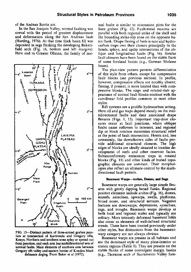
FIG. IS—Distinct pattern of three-armed graben junction at intersection of Kavirondo and Gregory rifts, Kenya. Northern and southern arms splay or spread out from junction, and each arm has multidirectional sets of normal faults. Main elements of southern arm between Gregory rift valley and eastern border of Kondoa block
delineate dogleg. From Baker et al (1972).
mal faults is similar to orientation plots for the Suez graben (Fig. 12). Fault-trend maxima are parallel with both regional strike of the shelf and the bounding strike-slip zone on the opposite basin flank. Drape flexing of beds is rare and hydrocarbon traps owe their closure principally to the bends, splays, and updip intersections of the oblique and longitudinal faults (Fig. 16). Similar fault closures have been found on the stable flank of some foreland basins (e.g., German Molasse basin).
The plan-view pattern permits differentiation of this style from others, except for compressive fault blocks (see previous section). In profile, however, compressive effects are notably absent; flexing, if present, is more limited than with compressive blocks. The steps and rotated-slab appearance of normal fault blocks contrast with the curvilinear fold profiles common to most other styles.
Rift systems are a prolific hydrocarbon setting. Here oil and gas traps depend mostly on the multidirectional faults and their associated drape flexures (Figs. 1, 13). Important trap-door closures occur at fault junctions, where oblique faults cause rollovers to intersect, and regionaj dip or block rotation maximizes structural relief at the point of fault intersection. Horsts and, less commonly, the downthrown sides of faults provide additional structural closures. The high edges of blocks are ideally situated to localize development of reefs and other reservoir facies. Subunconformity truncation traps in rotated blocks (Fig. 11) and other kinds of buried topographic closures are common. Their morphologies also reflect an ultimate control by the multidirectional fault pattern.
Basement Warps—Arches, Domes, and Sags
Basement warps are generally large simple flexures with gently dipping broad flanks. Regional positive elements include arches (Fig. 16), domes, massifs, anteclises, upwarps, swells, platforms, broad noses, and structural terraces. Negative features are downwarps, depressions, syneclises, sags, and troughs. Basement warps develop at both local and regional scales and typically are solitary. More intensely deformed basement folds also occur as elements of well-defined structural trends. These have been treated previously under other styles, but distinctions from the basement-warp category are not always obvious.
Basement warps are present in all habitats and are the dominant style of many plate-interior or era ton regions (Table 1). They are present on the stable flanks of some convergent margin basins (e.g., Thornton arch of Sacramento Valley fore-

1036 T. P. Harding and James D. Lowell
arc basin), stable flanks of transform margin basins (e.g., Bakersfield arch of San Joaquin Valley, Fig. 16) and in divergent margin basins (e.g., Cape Fear arch of Atlantic seaboard).
The Williston basin and adjoining shelf on the west (Fig. 17) demonstrate the style of basement warps and other structures common to intracra-tonic settings. Structures are of two general types; warps of various shapes and sizes, and narrow linear-faulted or fault-related features. Structures of the first type include the Miles City arch; Porcupine dome (Fig. 17, no. 7); Nesson anticline (Fig. 17, no. 1), a broad southward-plunging nose or arch with several culminations; the Bowdoin
(Fig. 17, no. 2) and Poplar domes (Fig. 17, no. 3) west of the basin proper; and the central-basin deep (Fig. 17, no. 4), which is an irregularly shaped sag or downwarp. The second type of structure, linear fault-associated features, is exemplified by the Cedar Creek anticline (Fig. 17, no. 5) which is essentially a monocline facing up the basin flank. Most of these Williston basin structures are solitary and do not share common geographic alignments or obvious trend associations; instead, their orientations include all quadrants of the compass.
Additional styles occurring in intracratonic regions are normal faults, either randomly dis-
BAKERSFIELD ARCH
TERTIARY CONTOURS
FIG. 16—Bakersfield arch, on stable east flank of San Joaquin Valley basin, California. Individual hydrocarbon traps are provided by secondary normal faulting, apparently concentrated by transverse arching, and by small basement domes at lower part of arch. Interference from en echelon fold set associated with San Andreas fauh
(west of map) is evident at southwest plunge of arch. Contours are of top of Tertiary. C.I. = 500 ft.

structural Styles In Petroleum Provinces 1037
STRUCTURE ON CRETACEOUS C.I. 500-
ICohm, 1962) 1. NESSON ANTICLINE 3. POPLAR DOME 5. CEDAR CREEK ANTICLINE 7. PORCUPINE DOME 2. BOVtfDOINOOME 4. CENTRAL BASIN DEEP 6. BROCKTON-.FROID FAULT ZONE • OIL AND GAS FIELDS
FIG. 17—Regional structure and main elements of Williston basin area. Trend orientations are diverse and continuity from one structure to another is absent (except in Bowdoin and Poplar domes).
persed or in well-defined zones and a few solitary wrench faults.
The structural genesis of basement warps is not well imderstood and they probably have multiple origins. Warps lack diagnostic features, such as drag and drape folds or trend patterns, to indicate directions of tectonic transport. Also lacking is an obvious plate-boundary association that could suggest a particular type of deformation. Differential regional subsidence or uplift has intuitive appeal as a cause of many intraplate warps. For example, the Miles City arch appears to be a residual high separating the Williston and younger Powder River basins (Fig. 17). The main Williston basin structures had dieir early growth in Or-dovician to Mississippian time (Hansen, 1972), synchronous with the first major phase of basin subsidence (Mallory, 1972). Differential subsidence or uplift could have occurred because of (1) irregularities in fundamental subcrustal processes and (2) large inhomogeneities within the crust.
Green (1977), in a review of crustal processes.
stated that the following have all been considered mechanisms of continental lithospheric thinning and subsidence: differential lithospheric cooling, phase changes, ductile flowage, subcrustal erosion, injection and stoping of dense material and related magma-chamber collapse, and surface erosion following thermal uplift. In addition, deep-seated listric normal faulting can also cause lithospheric thinning and associated subsidence.
Crustal inhomogeneities can modify structuiral responses to those deep-seated processes. Steep hnear zones of weakness such as preexisting wrench faults may be reactivated in a dip-shp mode. The reactivation could develop basement steps or linear monoclines such as the Paleozoic precursor of the Cedar Creek anticline (Fig. 17, no. 5). Some basement warps may be influenced by earlier buried fault blocks to the extent that they merge with the shallow expressions of fault-block styles (perhaps Porcupine dome. Fig. 17, no. 7).
The origin of domal features in contrast to lin-

1038 T. P. Harding and James D. Lowell
ear or blocklike structures is much more speculative. Irregularly shaped intrabasement masses with differing physical properties perhaps could subtly and locally retard or enhance regional subsidence.
Tectonic loading and sediment loading of fore-deeps have been considered mechanisms of warping in foreland settings. Crustal compression may be an additional agent for basement warping in such regions. The Williston basin structures were rejuvenated during the Laramide (Fig. 17) when compression was prevalent elsewhere in the Rocky Mountains province. Using earthquake focal plane solutions, Sykes and Sbar (1974) have demonstrated present compression within the North American plate.
The style and occurrence 'of basement warps pose problems for the simpUstic plate-tectonic approach that restricts structural development to the edges of so-called rigid plates and that implies mainly horizontal plate movement. Many basement warps in intraplate settings suggest first-order vertical movement in their development. Other features suggest midplate compression. All argue against simple plate tectonics as the exclusive cause of deformation. Clearly, vertical movements must occur within a larger scope of horizontal plate translations.
Basement warps can be differentiated from other basement-involved folds by their solitary occurrence, inconsistent orientations, lack of distinct trend patterns, and general lack of dependency on faulting for their development. Basement folds associated with block faulting reflect block-fault patterns as a genetic control. Basement folds associated with thrust or wrench faults demonstrate the characteristic trend patterns of these styles.
Positive basement warps, particularly where they intervene in areas of thick sedimentary cover, are the focal points for oil migration and accumulation (Fig. 16). They commonly persist over long periods of time and are particularly effective in localizing truncation, imconformity, convergence, and onlap in the sedimentary section. All of these factors can enhance entrapment of oil and gas (Fig. 1). Associated closures commonly are considerably larger and less segmented than the more complicated structures of other styles.
DETACHED STRUCTURES
DecoUement Tbrust-Fold Assemblages
Thrust-fold assemblages are an essential element of many convergent plate boundaries (Table 1). They may be present along the mobile flanks of back-arc and peripheral forelands, and
at trench inner slopes and outer highs (Dickinson, 1974). They occur as wide zones of deformed sedimentary cover on the external side, or outer fringe, of many orogenic belts (Fig. 3). Gradations to basement thrusting are common toward the internal, or core, regions (Fig. 4). The detached structures regionally are festooned into externally gently convex salients and more sharply concave reentrants (Fig. 3). Both salients and reentrants are comprised of parallel bands of thrusts and associated folds having relay trend patterns. Locally, thrusts overlap in cuspate arrangement convex in the direction of tectonic transport. Anticlines, where present, he in the hanging walls of the thrust faults and have axes parallel with the trends of the thrusts.
In profile, complex listric thrust faults that often merge with bedding at depth are characteristic (Fig. 19). Lithostratigraphic changes and attendant ductiUty contrasts are responsible for localization of the fault surfaces so that thrusts are generally parallel or subparallel with bedding in incompetent rocks and obhque to bedding in competent rocks. Thus, the thrusts alternately follow bedding, then ramp upward as step faults (Fig. 20). The faults almost invariably cut upsec-tion in the direction of relative tectonic transport of the hanging wall.
Where massive carbonate beds are a significant part of the deformed section, thrust sheets typically consist of repeated slabs. Where more duc-
O V E H T H R U S T FAULTS :
1. PROSPECT 5. MEADE
2. D A R B Y 6. PARIS
3. ABSAROKA
N O R M A L FAULTS ;
4. STAR V A L L E Y
A,B
(Adaptad From CohM, 1962)
_L
FIG. 18—Index map across Idaho-Wyoming thrust-fold belt. Seismic section and cross sections are shown
in Figures 19 and 20.
ME
RID
IAN
A
NT
ICU
NE
U
NIO
N O
IL
(36-
22N
-11S
W)
PA
N A
ME
RIC
AN
(2
»-22
N-1
14W
) E
AS
T
FIG
. 19
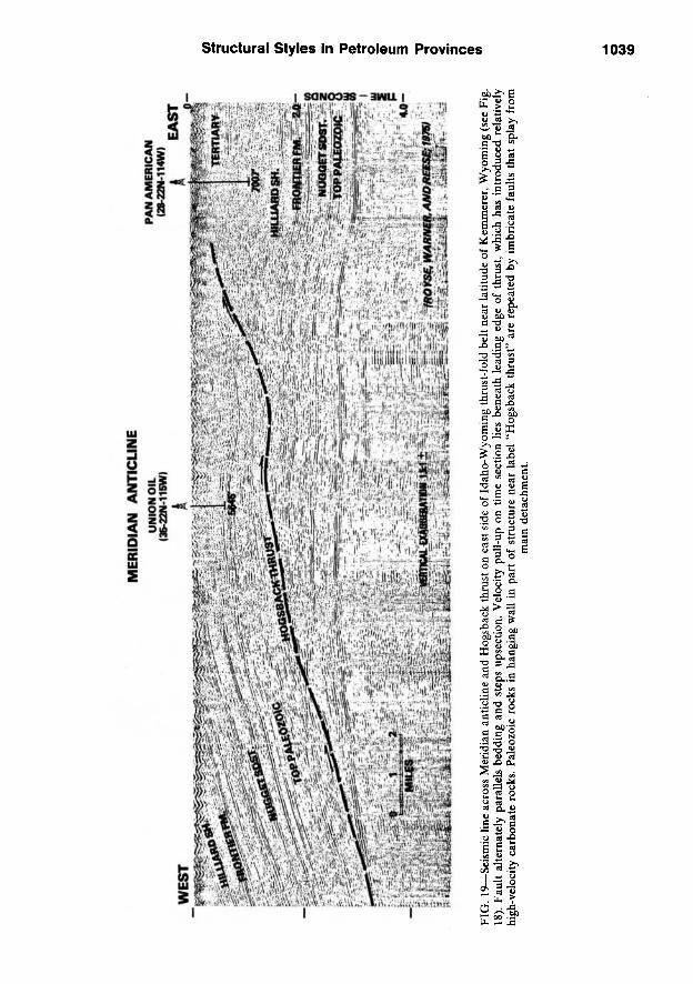
—Se
ismic
line
acr
oss
Mer
idia
n an
tichn
e an
d H
ogsb
ack
thru
st o
n ea
st s
ide
of I
daho
-Wyo
min
g th
rust
-fol
d be
lt ne
ar la
titud
e of
Kem
mer
er, W
yom
ing
(see
Fig
. 18
). Fa
ult
alte
rnat
ely
para
llels
bed
ding
and
ste
ps u
psec
tion.
Vel
ocity
pul
l-up
on
time
sect
ion
lies
bene
ath
lead
ing
edge
of
thru
st,
whi
ch h
as i
ntro
duce
d re
lativ
ely
high
-vel
ocity
car
bona
te r
ocks
. Pal
eozo
ic r
ocks
in
hang
ing
wal
l in
par
t of
str
uctu
re n
ear
labe
l "H
ogsb
ack
thru
st"
are
repe
ated
by
imbr
icat
e fa
ults
tha
t sp
lay
from
m
am d
etac
hmen
t.
c o
c"
w
•5"
(0
(D
o
©• c 3 o
< 5"
o
<D
cn

1040 T. P. Harding and James D. Lowell
WEST
tGeneralized from Royse, Warner arjd Reese, J975) NO VERTICAL EXAGGERATION
FIG. 20—Sequential evolution of Idaho-Wyoming thrust-fold belt at latitude of Auburn and Pinedale, Wyoming (see Fig. 18). Detachments form progressively from west to east, as rigid basement slab is presumably underthrust from east to west (Lowell, 1977). Wedging action of underthrusting Ufts earlier formed western thrust sheets (e.g., Paris thrust) so that older rocks are exposed. Reference numbers 1 through 7, which ultimately become present-day 30' longitude positions, demonstrate cumulation of shortening in sedimentary cover. A, B in bottom cross section
are later listric normal faults. Generalized from Royse et al (1975).

structural Styles In Petroleum Provinces 1041
— ( 3 ) ^
EAST
SEA LEVEL
END MARINE JURASSIC
-20,000'
-40 ,000 ' -
- 60 ,000 ' -
? ^ '?
a t i i — — ^ ^ ^ H = ^ = ^ = 1 ^
' • •' • ' • " • • ' • ' ' ' = ^ = ^ ^ - T —
. ;—̂-3 i — , .
PARIS THRUSTING, (U.fl .-L. K.)
SEA LEVEL
' ' ^^'-^T-t
-20,000' -
-40,000' -
-60,000' -
PtNEDALE. WYO.
FUruK THJkCe WIND HIVetf fMULT
MEADE THRUSTING (CONIACIAN ?) -60,ooo'
fuTun ( * )
M / W r AKO PKSKCT THUUSJS
MOXA ARCH
IND R I V E R M T N S . -20,000'-
-40,000'-
ABSAROKA THRUSTING (SANTONIAN ? - MAESTRICHTIAN) -60,ooo'-
-20,000' -
-40,000' -
D A R B Y - P R O S P E C T T H R U S T I N G ( U . P A L E O C E N E - E O C E N E ) -eo.ooo'-

1042 T. P. Harding and James D. Lowell
tile lithologies prevail, hanging-wall folds dominate. Such folds are characteristically asymmetric in the direction of relative transport of the upper plate. Structures generally are younger from the internal to the external side of the deformed belt (Fig. 20).
Anticlines with imbricate thrusts and broad folded thrust-fault structures (Fig. 19) occur across the breadth of a thrust-fold belt. The latter seem to be more common on the internal side and are usually located where faults step up in the sedimentary cover. Some thrust faults, back-thrusted or directed against the direction of relative transport of the upper plate, bound belts at their fronts and are termed "delta structures."
The process of thrusting areally extensive but thin sheets of sedimentary rocks for long distances has always been an enigma of structural geology. Overthrusting by compression (or "pushing" at the rear of thrust sheets) does not resolve yield-strength and stress-transmission problems in moving relatively weak materials. Gravity shd-ing, which invokes body forces to overcome these problems, also is not a viable universal mechanism of thrust emplacement because: (1) necessary regions of tectonic denudation are rarely observed, (2) penetrative deformation of sedimentary cover in the internal parts of erogenic belts is not explained, (3) basement slopes required for sliding are usually in the wrong direction, (4) the chronologic sequence of thrusting is reversed, and (5) the laterally extensive nature of thrust-fold belts that follow plate boundaries for thousands of miles is not compatible with the local aprons that would be expected from simple sliding of sedimentary cover off of uplifted regions. Although gravity sliding is not a suitable mechanism for emplacement of thrust sheets on a regional scale, it has created smaller deformed belts where a slope on the base of the detached sedimentary section exists over a limited area, such as the Bearpaw Mountains of north-central Montana.
As an alternative to regional gravity sliding, a model of gravity spreading has been proposed (Bucher, 1956; Price, 1969, 1973; Price and Mountjoy, 1970; Elliott, 1976) in which only a slope on top of the sedimentary prism, and not on the actual thrust surfaces, is required to facihtate thrust-sheet emplacement. The structural results of gravity spreading can also be accommodated by the model of underthrusting described in the next paragraph and the two need not be mutually exclusive. However, at least in the Idaho-Wyoming thrust belt, thrusting began before any significant surface slope was attained (Fig. 20).
Large-scale plate movement provides a ratio
nale for underthrusting between oceanic and continental lithospheric plates and within continental lithosphere. The model of stripping and stacking of sedimentary cover by crustal underthrusting in the landward slopes of oceanic trenches (Seely et al, 1974) appears to satisfy many of the critical relations in thrust-fold belts generally (Lowell, 1977). Underthrusting obviates problems of rock strength and stress transmission in that there need be no deformation of layered sedimentary rocks lying on rigid sialic basement until these rocks reach a zone of uncoupling (Fig. 20). The wedging action provided by the insertion of successive thrust sheets from below is also a mechanism for rotation and uplift of earlier formed thrusts and thereby accounts for the exposure of older rocks in the more internal parts of most orogenic belts. Finally, the age progression of detached thrusting from older to younger toward the underthrust plate is compatible with and even predicted by underthrusting (Fig. 20).
Thrust structures can be identified on seismic profiles by two main criteria: (1) shallow compressive folding above essentially undeformed reflectors and (2) stretches of backlimb dips that ultimately converge with underlying reflectors, generally in a direction opposite to tectonic transport (Fig. 19, left margin). In the latter way, thrusts do not demonstrate the persistent regional uplift present in many compressive fault blocks. The typical convergence of beds on one flank only reflects the asymmetry of the detachment. The bed geometry contrasts with the more symmetric convergence of reflectors apparent down both flanks of other detachments, such as flower structures (cf. Figs. 6 and 19) and salt pillows.
The decoUement thrust-fold assemblage is further distinguishable from other thrust styles on the basis of. distribution patterns. On a very large scale, many thrust-fold assemblages have great lateral persistence. Wrench-fault-associated assemblages have more finite, limited distributions. The distribution of compressive fault blocks is more random.
The sinuosity of most thrust-fold belts is also distinctive. On an intermediate scale, individual relay trends curve with this sinuosity, thus conforming to the outline of salients or reentrants. Thrusts and folds associated with wrench faults ideally trend obliquely to the outline of the deformed zone (cf. Figs. 3 and 5). On a more local scale, the relay patterns of thrust belts differ from both the en echelon trends of wrench-associated structures and the rhombic or cross-trended patterns of fault blocks (cf. Figs. 3 and 8).
Most petroleum in thrust-fold belts has been trapped in asymmetric, hanging-wall folds and

structural Styles In Petroleum Provinces 1043
the lead edges of thrust sheets (Fig. 1). Effective closures are commonly located at a relatively external part of a belt and at generally shallow to moderate (10,000 ft; 3,000 m) structural levels. Closures at these positions have been only slightly to moderately disrupted by faulting allowing reservoir continuity and migration pathways to remain essentially intact. Structures in this setting along the Zagros foldbelt of Iran account for more than three-fourths of the production from the world's thrust-fold belts. Enormous volumes of hydrocarbons are contained in fractured carbonate rocks on very high-amplitude, structurally simple, detached anticlines (Fig. 4). Significant production occurs also in the Canadian Rockies where traps are mainly at the lead edges of thrust sheets. Recently, important discoveries have been made in the Idaho-Wyoming thrust-fold belt; all traps found so far are hanging-wall folds.
Detached Normal-Fault Assemblages
Normal faults detached from basement occur in a wide variety of tectonic terranes but many are secondary elements of other structural styles. Most normal faults on the crests of folds and above diapirs (Fig. 1) are secondary faults. In other places, for example the Gulf Coast basin of Texas and Louisiana, detached normal faults occur in regional zones and are a dominant mode of deformation. Such zones commonly have unique structural assemblages and comprise a distinct structural style (Fig. 21).
The most common types of primary detached normal faults are down-to-basin faults that develop in ductile lithologies and have a close relation between displacement history and sedimentation. Interval thicknesses increase abruptly along the downthrown sides of these faults and there is a
NW SE M FT.
M s=^-::: A iis;̂ ;̂ -:̂ ;:;;-;":;--;" - " - - ; S ^ A S ^
SEC.
1.0
2.0
3.0
4.0
' ^ (Bruce, 1973) VERTICAL EXAGGERATION :
MILES
; ^ ? 5 ^ . r ? ^ 5.0
FIG. 21—Syndepositional, detached normal fault assemblage in Tertiary sediments of south Texas part of Gulf Coast basin. M, master down-to-basin synthetic fault. A, antithetic faults. Ro, rollover anticline with basinward migration of crest at depth. Northwest-dipping events beneath M fault would migrate to right to form part of
rollover anticline. Some assemblages have only synthetic faults.

1044 T. P. Harding and James D. Lowell
generally progressive downward increase in throw through much of the fault profile. These syndepositional faults also have beerl termed "regional faults," "growth faults" (Ocamb, 1961), "contemporaneous faults" (Hardin and Hardin, 1961), and "down-to-basin faults" (Cloos, 1968). These attributes, however, are obviously not restricted to just one type of fault and such terminology does not describe a discrete style.
Postdepositional detached normal faults, whose structural geometries are similar to the syndepositional types, have developed where a gradient has been present for sliding, for example, the topographically highest end of the Heart Mountain fault (Pierce, 1957). Detached normal faults, some of which flatten on the ramped portion of earlier thrust faults, are also present in thrust-fold belts (Fig. 20, faults A, B). Such faulting occurred in the Idaho-Wyoming thrust belt during a later episode of regional extension that was unrelated to thrusting but did affect deposition and preservation of section on the down-thrown side of faults. Others apparently developed at the conclusion of thrusting and do not show contemporaneous expansion of sedimentary section. All of these postdepositional detached normal faults developed in relatively competent rocks. Their importance in petroleum provinces is minor compared to the Gulf Coast variety.
Syndepositional detached normal faults develop a dominant style in thick, generally regressive clastic sequences that have been built out into un-confined depositional sites, such as large deltas and the edges of continental shelves on passive continental margins (Todd and Mitchum, 1977, Fig. 9). There, rapidly deposited, semiconsolidat-ed sediment is free to move basinward. In addition to the process of creep, faulting is often closely associated with the growth of salt (Lehner, 1969; Spindler, 1977) and shale structures (Bruce, 1973; Dailly, 1976). The largest displacement faults, termed "synthetic," are downthrown toward the basin. Some secondary faults on individual structures have up-to-basin displacements ("antithetic") and generally terminate against the synthetic faults (Fig. 21). Other antithetic faults are primary, and have major displacements and structural characteristics similar to the regional synthetic faults (Spindler, 1977).
In profile view, many syndepositional faults dip subparallel with the flank of an underlying shale ridge or salt diapir, and may use the contacts with the overlying sediments for their detachment zones (Fig. 22). The faults are distinctively listric and can flatten downdip to merge parallel with bedding (Fig. 21) or dissipate within a chaotic slide-flow zone (J. S. Shelton, personal
commun., 1978; Rider, 1978). In some places the depositional top of salt is a detachment surface (W. F. Bishop, 1973). Syndepositional faults can also terminate in an adjacent shale ridge (Fig. 22) or die out in the bottom of "depopods" between shale or salt diapirs (McGookey, 1975, Fig. 13). Compressional features have been reported at the toes or downdip ends which are sites of crumpling and telescoping of mobile section within the detached masses (Amery, 1969; Humphris, 1976; Dailly, 1976). Upward the displacement can decrease to nil owing to greater sediment filling of the downthrown side of the fault. Continued basin subsidence and late rejuvenation of some buried faults can reextend them to the surface, which has produced faults with both earlier growth and later postdepositional characteristics. The shallower, rejuvenated segments have displacement magnitudes that are constant throughout their profile, and formation thicknesses are the same in upthrown and downthrown blocks.
Detached normal-fault assemblages are complex (Fig. 21). The listric nature of many detached faults requires a backward rotation of beds into the steeper part of the fault (Cloos, 1968). In some places where rotation reverses basinward dip, a detached "rollover" anticline is formed on the downthrown side of and parallel with the master fault (top of Fig. 23). Down-thrown beds are thickest adjacent to the fault and generally thin away from it in this example. Structural warping and consequent closure parallel with fault strike are thought to be the result of fault curvature and displacement variations along the trend of the fault that also cause changes in stratigraphic thickness within the downthrown block (Roux, 1977). The broad shallow rollover is commonly complicated at depth by increased faulting which segments the reverse dip into separated rotated fault blocks and increases the breadth of the counter-regional dip (Fig. 23, lower map). The overall rollover structure shifts basinward with depth but dip reversal can occur within different fault blocks at different locations and depths, and some blocks have no internal flexing (Fig. 24, at level of Kings Bayou sand).
The extensional tectonics in the Gulf Coast basin are further complicated by the presence of other kinds of normal faults. These include numerous local keystone faults above salt or shale domes and turtle structures, and more areally extensive detached "collapse faults" (Seglund, 1974) which circumscribe salt or shale withdrawal basins. Older basement-involved normal faults, thought to have facilitated opening of the Gulf of Mexico (Freeland and Dietz, 1971), may have been rejuvenated during prolonged subsidence of

structural Styles in Petroleum Provinces 1045
NORTH
Hail20IIIU SCIIE IN HUES (Woodbury et al, 1973)
FIG. 22—Syndepositional detached normal faults in outer continental shelf of Gulf Coast basin, Louisiana and Texas. Faults sole out at salt-overburden contact identified by strong reflector and associated diffractions below 15,000 ft (4,500 m) in center of cross section. Presence of diapiric shale core (center) or salt diapir (right) below upthrown side of large growth fault is reported to be very common in this
province (Woodbury et al, 1973).
the basin. If so, they could cut upward into the regional detached structures and could even trigger the shallower detached faulting.
Regional elements of the detached normal fault style in the United States Gulf Coast (Cohee, 1962) and in the Niger delta (Fig. 25) are present in wide, arcuate, parallel bands that trend subpar-allel with basin outline and/or depositional strike. Individual faults in map view are usually cuspate, concave in the direction of tectonic transport, and hnk to form an internally complex, anastomosing pattern. Fault zones become progressively younger in the direction of sedimentary progradation. Within a particular zone, however, the local timing for individual faults may reverse this sequence.
The detached normal-fault style in the Gulf Coast basin has been attributed to several causes. Large basement subsidence is required to provide a site for relatively rapid, thick deposition and to maintain a regional slope for basinward transport. Positive uplifts, other than those caused by diapirism, are lacking. Yorston and Weisser (1976) and W. F. Bishop (1973) have emphasized gravity sliding in several areas. Lehner (1969),
W. F. Bishop (1973), and Spindler (1977) have cited salt withdrawal in areas with significant salt. Differential sedimentary loading and compaction of shales have been emphasized by Bruce (1973); Roux (1977) associated the style with differential subsidence and compaction. Cloos (1968) has reproduced the basinwide fault pattern and characteristics of individual structural assemblages with regional gravity creep and local sliding models, respectively. Many authors (e.g., Bruce, 1973) have noted the importance of overpressured shales in the faulting process.
Yorston and Weisser (1976) suggested that two different detached normal-fault assemblages can result from downslope gravity sliding: peripheral breakaway faults, and local slope transport faults. The first occurs near the updip edge of the regional fault system. In the northeastern Gulf Coast, they utilize salt for their detachment. Movement in this region apparently was facilitated by sediment loading of downdropped blocks and consequent flowage of salt from beneath the loaded blocks (W. F. Bishop, 1973). The development of local slope transport faults is thought to involve successive detachment and basinward creep of

FIG. 23—Detail of detached normal fault pattern, southern Louisiana Gulf Coast. Parallelism of axis of rollover anticline on downthrown side of associated down-to-basin fault is apparent in top map. Rotation of regional dip
into deeper faults increases landward-dipping segments that form individual fault traps in bottom map.

structural Styles in Petroleum Provinces 1047
lUMff-
14.000'- 0
FEET ltdiiiilBd horn Shane, 197V NO VERTICAL EXAGGERATION
FIG. 24—North-south cross-section AA', across East Cameron area. United States Gulf Coast, showing normal fault pattern. Rollover has been removed by rotation of regional dip (Fig. 23). Location of cross
section is shown on Figure 23.
BENIN 100 km.
-SYNTHETIC FAULTS
•ANTITHETIC FAULTS
FIELDS
• ' • ^ - ^ ^ .
(A fter Weber and Daukoru, 1976)
FIG. 25—Syndepositional detached normal faults in Niger delta demonstrate parallel crescentic trends and complex linkage of individual faults that are concave toward direction of transport.
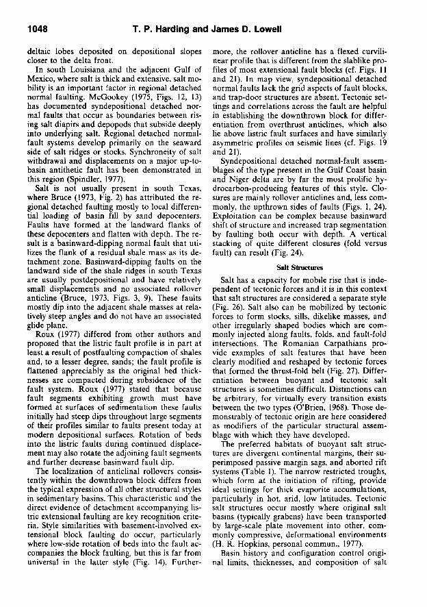
1048 T. P. Harding and James D. Lowell
deltaic lobes deposited on depositional slopes closer to the delta front.
In south Louisiana and the adjacent Gulf of Mexico, where salt is thick and extensive, salt mobility is an important factor in regional detached normal faulting. McGookey (1975, Figs. 12, 13) has documented syndepositional detached normal faults that occur as boundaries between rising salt diapirs and depopods that subside deeply into underlying salt. Regional detached normal-fault systems develop primarily on the seaward side of salt ridges or stocks. Synchroneity of salt withdrawal and displacements on a major up-to-basin antithetic fault has been demonstrated in this region (Spindler, 1977).
Salt is not usually present in south Texas, where Bruce (1973, Fig. 2) has attributed the regional detached faulting mostly to local differential loading of basin fill by sand depocenters. Faults have formed at the landward flanks of these depocenters and flatten with depth. The result is a basinward-dipping normal fault that utilizes the flank of a residual shale mass as its detachment zone. Basinward-dipping faults on the landward side of the shale ridges in south Texas are usually postdepositional and have relatively small displacements and no associated rollover anticline (Bruce, 1973, Figs. 3, 9). These faults mostly dip into the adjacent shale masses at relatively steep angles and do not have an associated glide plane.
Roux (1977) differed from other authors and proposed that the listric fault profile is in part at least a result of postfaulting compaction of shales and, to a lesser degree, sands; the fault profile is flattened appreciably as the original bed thicknesses are compacted during subsidence of the fault system. Roux (1977) stated that because fault segments exhibiting growth must have formed at surfaces of sedimentation these faults initially had steep dips throughout large segments of their profiles similar to faults present today at modern depositional surfaces. Rotation of beds into the hstric faults during continued displacement may also rotate the adjoining fault segments and further decrease basinward fault dip.
The localization of anticlinal rollovers consistently within the downthrown block differs from the typical expression of all other structural styles in sedimentary basins. This characteristic and the direct evidence of detachment accompanying listric extensional faulting are key recognition criteria. Style similarities with basement-involved extensional block faulting do occur, particularly where low-side rotation of beds into the fault accompanies the block faulting, but this is far from universal in the latter style (Fig. 14). Further
more, the rollover anticline has a flexed curvilinear profile that is different from the slablike profiles of most extensional fault blocks (cf. Figs. 11 and 21). In map view, syndepositional detached normal faults lack the grid aspects of fault blocks, and trap-door structures are absent. Tectonic settings and correlations across the fault are helpful in establishing the downthrown block for differentiation from overthrust anticlines, which also lie above listric fault surfaces and have similarly asymmetric profiles on seismic lines (cf. Figs. 19 and 21).
Syndepositional detached normal-fault assemblages of the type present in the Gulf Coast basin and Niger delta are by far the most prolific hydrocarbon-producing features of this style. Closures are mainly rollover anticlines and, less commonly, the up thrown sides of faults (Figs. 1, 24). Exploitation can be complex because basinward shift of structure and increased trap segmentation by faulting both occur with depth. A vertical stacking of quite different closures (fold versus fault) can result (Fig. 24).
Salt Structures
Salt has a capacity for mobile rise that is independent of tectonic forces and it is in this context that salt structures are considered a separate style (Fig. 26). Salt also can be mobilized by tectonic forces to form stocks, sills, dikelike masses, and other irregularly shaped bodies which are commonly injected along faults, folds, and fault-fold intersections. The Romanian Carpathians provide examples of salt features that have been clearly modified and reshaped by tectonic forces that formed the thrust-fold belt (Fig. 27). Differentiation between buoyant and tectonic salt structures is sometimes difficult. Distinctions can be arbitrary, for virtually every transition exists between the two types (O'Brien, 1968). Those demonstrably of tectonic origin are here considered as modifiers of the particular structural assemblage with which they have developed.
The preferred habitats of buoyant salt structures are divergent continental margins, their superimposed passive margin sags, and aborted rift systems (Table 1). The narrow restricted troughs, which form at the initiation of rifting, provide ideal settings for thick evaporite accumulations, particularly in hot, arid, low latitudes. Tectonic salt structures occur mostly where original salt basins (typically grabens) have been transported by large-scale plate movement into other, commonly compressive, deformational environments (H. R. Hopkins, personal commun., 1977).
Basin history and configuration control original limits, thicknesses, and composition of salt

structural Styles in Petroleum Provinces 1049
and overburden. In this way, they influence the general distribution (Fig. 28) and types of buoyant salt features. Basinward increase in original salt thickness is ideally expressed by the following progression of structures (Trusheim, 1960; Hughes, 1968): (1) downbends in sedimentary rocks above areas of salt withdrawal along the original depositional edge of the salt; (2) pillows of salt that can coalesce along strike to form low ridges; (3) anticlines and low domes of salt that can increase in relief to piercement features; and (4) walls of piercement salt.
In the coastal plain of the Gulf Coast and southward to the lower continental shelf the progression of structure is from (1) small, elongate, isolated spines to (2) progressively closer spaced, larger spines, and (3) almost continuous ridges and irregularly shaped large massifs (Stude, 1978). Growth sequences of offshore Gulf Coast structures are from initial salt swells to narrower ridges or stocks and finally to narrow salt chimneys or spines 2 to 4 n. mi in diameter (Lehner, 1969). Both the form of the salt features themselves and the effect on the adjacent sedimentary section of simultaneous lateral and vertical salt movement are important in understanding and exploring salt basins.
Distribution of salt domes in the absence of tectonic influence is typically in irregular clusters (Fig. 28, upper). In some places salt ridges or walls tend to be subparallel (Fig. 28, middle) and may be aligned with basin margins. Extensive massifs and ridges are closely spaced in a large area of the lower continental shelf of the Gulf Coast basin, but mostly lack discernible trend patterns (Martin, 1976).
A widely accepted mechanism for diapirism has been the movement of salt by buoyancy (Net-tleton, 1934). Alternatives, which explain certain aspects of diapirism not resolved by the buoyancy model, have been proposed by Barton (1933), Bornhauser (1969), and R. S. Bishop (1978). According to R. S. Bishop (1978) initial salt movement occurs during progradation of sedimentary overburden across essentially exposed salt deposits on the basin floor (McGookey, 1975). The mobile evaporites flow both horizontally and vertically as waves or pillows in front of the advancing overburden. Flowage can occur before overburden is sufficiently thick to cause a density inversion between salt and sedimentary cover. The sedimentation rate, progradation rate, regional dip, sediment density, and thickness of both the mobile substrate and overburden all affect the size and shape of incipient salt structures. Slow, even accumulation of overburden results in salt structures with random distribution. Focused
loading concentrates structures in specific sites and can align them parallel with thick areas of overburden (R. S. Bishop, 1978, Fig. II).
As overburden buries the initial salt structure, horizontal flow is restricted but salt buoyancy may develop and vertical growth may continue as an unrestrained extrusion to the seafloor. Extrusion alleviates the space problems that arise where the rising diapir is required to force aside its overburden.
If the density inversion (buoyancy) disappears, extrusion will cease and diapirism continues only as a buried intrusion. The cause of diapirism at this stage may be selective dissolution and removal of salt by migrating subsurface fluids (upsetting mass equilibrium) or differential loading (e.g., salt flowing out from under a preferentially loaded rim syncline). According to R. S. Bishop (1978) growth of many Gulf Coast diapirs alternated between extrusion and intrusion.
Continuous vertical diapirism can be restrained by significant increases in overburden thickness or strength. Growth then becomes sporadic and occurs only by fracturing and forceful injection of salt into the overburden, which occur only when the pressure within the diapir, arising from sediment loading, becomes sufficient to rupture the overburden (R. S. Bishop, 1978). Deeply buried diapirs may expand laterally prior to vertically fracturing their overburden. When fracturing does not occur, the diapir ceases to grow, even if evaporite supply is sufficient.
The vertical rise of salt cores causes localized stretching and detached normal keystone faulting of the sedimentary overburden. Faulting can be highly complex and patterns are mostly radial and transverse. Stude (1978) has documented the faulting sequence at the South Timbalier Block 54 salt dome in offshore Louisiana, "The older gra-ben faults moved farther from the crest of the salt and became inactive (as the dome continued to pierce through the overburden and widen). These faults were replaced by younger faults over the salt crest." Currie (1956) has modeled salt-dome growth and demonstrated similar timing but other sequences are also possible (Stude, 1978).
Distinctive profile characteristics facilitate identification of salt structures on seismic lines. On Figure 26, residual salt highs are considered remnants of the original salt bed left by incomplete evacuation of salt. Turtle structures are inverted sediment-filled lows that formed above areas of early salt withdrawal. Rim synclines reflect the growth history of the associated salt dome.
The most prolific salt-related traps are those that are not pierced by evaporites at reservoir levels (Fig. 1). These include reservoirs concordant

1050 T. P. Harding and James D. Lowell
I I t -I
{ADAPTED FROM TUCKER AND YORSTON, 1973)
VERT. EX.: 5y2X1± FEET
FIG. 26—Seismic section across Hainesville dome (center), east Texas, with structures as indicated. Higher velocity of salt relative to surrounding rocks at velocity anomalies at left and center results in "pull-up" of time section. Velocity anomaly at right shows as depression, because salt here has lower velocity than laterally adjacent rocks.

structural Styles in Petroleum Provinces 1051
STRUCTURES: SALT RELATED 1. PIERCEMENT SALT DOME 5. PRIMARY SALT WITHDRAWAL
(la. CAP ROCK) SYNCLINE 2. NON - PIERCEMENT SALT ANTICLINE 6. RIM SYNCLINE 3. RESIDUAL SALT HIGH 7. NORMAL FAULTS 4. TILTED TURTLE STRUCTURE VA - VELOCITY ANOMALY
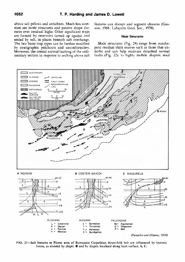
1052 T. P. Harding and James D. Lowell
above salt pillows and antichnes. Much less common are turtle structures and passive drape closures over residual highs. Other significant traps are formed by reservoirs turned up against and sealed by salt, in places beneath salt overhangs. The two basic trap types can be further modified by stratigraphic pinchouts and unconformities. Moreover, the crestal normal faulting of the sedimentary section in response to arching above salt
features can disrupt and segment closures (Gus-sow, 1968; Lafayette Geol. Soc, 1970).
Shale Structures
Shale structures (Fig. 29) range from nondia-piric residual shale masses such as those that underlie and can help motivate detached normal faults (Fig. 22), to highly mobile, diapiric mud
QUATERNARY
L \ \ \ 1 PLIOCENE
MIOCENE
I PALEOGENE
PLIOCENE U = Levantine
Dacian Pontian Meotian
MIOCENE s = Sarmatian t = Tortonian h = Helvetian b'= Burdtgalian
PALEOGENE dq= Aquitanian ol = Oligocene 1 = Salt
fParaschiv and Olteanu, 1970)
FIG. 27—Salt features in Ploesti area of Romanian Carpathian thrust-fold belt are influenced by tectonic forces, as attested by diapir, B and by diapirs localized along fault surface, A, C.

structural Styles In Petroleum Provinces 1053
lumps. They are not limited to any particular structural or plate-tectonic environment, as attested by their widespread occurrence. Shale structures, however, are perhaps best known in thick, modern clastic deltas (Table 1; R. S. Bishop, personal commun., 1977) where high deposi-tional rates create thick sequences that retard water expulsion from fine mud fractions. Muds are consequently undercompacted, have abnormally high pore-fluid pressures, and thus can react
in a highly mobile buoyant manner. In south Texas, shale ridges develop by differ
ential compaction resulting from differential loading and shale diagenesis. Ridges here are aligned subparallel with regional strike, and are commonly tens of miles long, up to 25 mi (40 km) wide, and 10,000 ft (3,000 m) high (Bruce, 1973). In Trinidad, shale diapirism appears to be tec-tonically motivated, with diapirs present along major strike-slip faults. Shale structures can also
(Heybroek, 1968)
•LIMITS OF ZECHSTEIN
LIMITS OF SALT STRUCTURE
SALT PILLOWS
SALTPIERCEMENTS
FIG. 28—Distribution of primarily buoyant salt features in southern North Sea and adjacent parts of Netherlands, northwest Germany, and northern Denmark as known in 1968. Randomly trended, clustered structures prevail in
north part; trends are more linear and locally parallel in south.

1054
0
T. P. Harding and James D. Lowell
5 10 15Km
•• 1
-2 a to
- 3
(Dailly 1976) 1) FLOWING SHALE
2) UNDERCOMPACTED SHALE
VERTICAL EXAGGERATION 2:1 ±
3) ALTERNATION SERIES
4) CONTINENTAL SANDS
FIG. 29—Seismic expression of shale diapirs within deltaic sequence.
result from crowding and shortening of the sedimentary cover during downslope creep as at the toes of syndepositional detached normal-fault assemblages.
Morphologic characteristics of salt structures are also shared by most abnormally pressured shale structures formed in passive tectonic environments. Indeed, the two are known to occur together to form compound domal masses (Atwa-ter and Forman, 1959; Musgrave and Hicks, 1968). On reflection seismic sections, both salt and shale flowage usually are manifested by reflection cutouts (Musgrave and Hicks, 1968).
Differentiation of salt and shale is possible when acoustic velocity information is available inasmuch as shale flowage masses typically have only about half the velocity of salt. Moreover, shale features seem to lack the well-defined rim synclines frequently associated with salt bodies, probably because salt flowage can occur at substantial distances from a developing dome, whereas shale flowage involves less lateral movement. Slower flow rates over longer periods in salt-structure growth may also be important factors.
Greater shale compactibility may be a main cause of differences in the development of shale and salt structures according to R. S. Bishop (1978). Salt diapirs can pierce thicker overburden
and rise to greater heights. Bishop (1978) wrote:
During burial, the ratio of salt to the overburden density increases, and the salt diapir may stay near the surface and remain vertically unconstrained throughout sedimentation. In contrast, the ratio of shale density to its overburden may decrease during burial (due to shale compaction), thereby causing intrusion at a slower rate than sedimentation. This results in deeper burial of the shale diapirs; the consequence is vertical constraint and perhaps cessation of the diapirism.
Closures related to shale masses have not trapped nearly so much petroleum as that attributable to most other structural styles. O'Brien (1968), however, has cited numerous shale domes and features associated with mud volcanoes as significant sources of hydrocarbons.
CONCLUSIONS AND APPLICATIONS
In general terms, the common geologic structures of sedimentary basins are distributed in definable, interrelated suites that constitute styles. Their preferred tectonic habitats result broadly from lithospheric plate movements but are also controlled by other factors. The type of deformation and tectonic history of specific regions can only be determined by correct differentiation of styles. The style approach can then provide a first approximation of the kinds of hydrocarbon traps

structural Styles In Petroleum Provinces 1055
and the general distribution patterns to be expected during exploration.
Variations in Structural Style
Many factors contribute to the development of individual closures and can influence the expression of structural style or control its areal limits. Of prime importance are the physical properties of the deformed region, such as thickness and li-thology of the sedimentary cover, and mobility and preexisting structural fabric of the basement. Mobile hthologies in the basin fill, such as evapo-rites and undercompacted shales, directly control the occurrence of salt and shale structures and are critical in the development of syndepositional detached normal faults. Greater basement ductility can enhance or even control the presence of folds in basement-involved styles (e.g., west side of San Joaquin Valley, Harding, 1976) although a lack of ductility may result in a brittle structural response (e.g., Wyoming foreland). Older basement fabric can localize fault-block closures.
Style expression is also influenced by tectonic variables such as intensity, rate, duration, and stage of deformation (Fig. 5), and differences of applied stress. In addition, sedimentation contemporaneous with deformation and the structural level of available control can determine the structural geometry observed. Gentle rejuvenation of dip-slip faulting concurrent with sedimentation, for example, results in drape flexures of greater amplitude that become the shallow expression of block faulting. In each of the described situations, however, the basic style category is still discernible.
Diversity of Styles Occurrence
For convenience, we have described each style individually, but actual occurrence of structures frequently indicates transition between styles. Detached thrust systems, for example, can ultimately root downdip in basement thrusts and in places merge along strike with blocklike compressive features. In other settings, syndepositional detached normal faults change downdip into detached thrust features. Transitions in the wrench style from structures that are dominantly compressive to those that are extensional can occur along a single zone.
The structures of a sedimentary basin commonly include several styles and transitions between styles and these can have either separate or overlapped distributions. In the San Joaquin Valley (Harding, 1976, Fig. 1) a wrench-fault assemblage dominates the mobile southwest flank, a sahent of locally detached thrust faults predominates at the south end where right- and left-lateral
strike-slip faults converge, and basement warps with secondary normal faults dominate the stable northeast flank.
Some extensional settings can combine basement fault blocks with salt and/or shale structures and syndepositional detached normal faults, often superimposed at different levels (Fig. 22, in part). Compressive settings can mix detached thrusts and folds, basement thrusts or compressive block faults, wrench-related features, and, with the presence of mobile substrata, tectonic salt and/or shale structures (Fig. 3). Each basin has a unique history and styles can be further complicated by the overprints of fundamentally different stress systems through time.
No style is universally present within its preferred habitat, nor is a style always consistently developed where it is present. Foreland settings present the greatest extremes. In contrast with the Wyoming foreland, the Alberta basement foreland of the Canadian Rockies on strike has very few structures (King, 1969). Late Paleozoic structures along the foreland of the approximately coeval Ouachita-Llanoria fold-thrust belt are widespread and highly varied (King, 1969). Included are (1) normal block faults on the stable north flank of the Arkoma basin, (2) wrench faults along the trend of the Ardmore-Anadarko basin, (3) broad basement arch at the Llano uplift, and (4) dominantly compressive fault blocks in the Permian basin. Obviously, forces of plate convergence can be manifested in different ways. Earlier structures apparently controlled the style and/or distribution of some of this foreland deformation, but still other factors may have been important.
Identification of Structural Style
Two major factors—variations in style expression and complications in style occurrence—can make differentiation of styles exceedingly difficult; this may be especially true of convergent margin settings and their orogenic belts.
Many structural patterns can be developed in several ways, and "false" patterns arising from unique circumstances must be ruled out. For example, an overprint of faults trending obliquely to an earlier thrust-fold belt could result in a misleading en echelon appearance. Linear strike-sUp fault sets superimposed on each other could result in a fault-block appearance. A pattern usually typical of a particular tectonic regime can be simply the result of unique physical properties in the deformed terrane such as a strong basement grain or anisotropy within the sedimentary cover. Determination of several recognition criteria is often essential. Consideration of alternatives is always

1056 T. P. Harding and James D. Lowell
necessary and requires equal familiarization with all styles.
REFERENCES CITED
Amery, G. B., 1969, Structure of Sigsbee Scarp, Gulf of Mexico: AAPG Bull., v. 58, p. 2480-2482.
Anderson, E. M., 1942, The dynamics of faulting and dyke formation with application to Britain: Edinburgh and London, Oliver Boyd, 206 p. (rev. ed. 1951).
Atwater, G. I., and M. J. Forman, 1959, Nature of growth of southern Louisiana salt domes and its effect on petroleum accumulation: AAPG Bull., v. 43, p. 2592-2622.
Badgley, P. C , 1965, Structural and tectonic principles: New York, Harper and Row, 521 p.
Baker, B. H., P. A. Mohr, and L. A. J. Williams, 1972, Geology of the Eastern rift system of Africa: Geol. Soc. America Spec. Paper 136, 67 p.
Bally, A. W., 1975, A geodynamic scenario for hydrocarbon occurrences: 9th World Petroleum Cong. Proc, V. 2, p. 33-44.
D. L. Gordy, and G. A. Stewart, 1966, Structure, seismic data, and orogenic evolution of southern Canadian Rocky Mountains: Bull. Canadian Petroleum Geology, V. 14, p. 337-381.
Barton, D. C , 1933, Mechanics of formation of salt domes, with special reference to Gulf Coast salt domes of Texas and Louisiana: AAPG Bull., v. 17, p. 1025-1083.
Beloussov, V. V., 1959, Types of folding and their formation: Internat. Geol. Rev., v. 1, p. 1-21.
Bishop, R. S., 1978, Mechanism for emplacement of piercement diapirs: AAPG Bull., v. 62, p. 1561-1583.
Bishop, W. F., 1973, Late Jurassic contemporaneous faults in north Louisiana and south Arkansas: AAPG Bull., v. 57, p. 858-877.
Bornhauser, M., 1969, Geology of Day dome (Madison County, Texas)—a study of salt emplacement: AAPG Bull., v. 53, p. 1411-1420.
Bruce, C. H., 1973, Pressure shale and related sediment deformation—mechanisms for development of regional contemporaneous faults: AAPG Bull., v. 57, p. 878-886.
Bucher, W. H., 1956, Role of gravity in orogenesis: Geol. Soc. America Bull., v. 67, p. 1295-1318.
Burchfiel, B. C , and G. A. Davis, 1975, Nature and controls of Cordilleran orogenesis, western United States—extensions of an earlier synthesis: Am. Jour. Sci., v. 275-A, p. 363-396.
Cloos, E., 1968, Experimental analysis of Gulf Coast fracture patterns: AAPG Bull., v. 52, p. 420-444.
Cohee, G. V., 1962, Tectonic map of the United States: U.S. Geol. Survey and AAPG, scale, 1:2,500,000.
Currie, J. B., 1956, Role of concurrent deposition and deformation of sediments in development of salt-dome graben structures: AAPG Bull., v. 40, p. 1-16.
Dailly, G. C , 1976, A possible mechanism relating pro-gradation, growth faulting, clay diapirism and over-thrusting in a regressive sequence of sediments: Bull. Canadian Petroleum Geology, v. 24, p. 92-116.
Darton, N. H., 1906, Cloud Peak-Fort McKinney folio.
Wyoming: U.S. Geol. Survey Geol. Atlas, Folio 142, 16 p.
Dewey, J. F., and J. M. Bird, 1970, Mountain belts and the new global tectonics: Jour. Geophys. Research, v. 75, p. 2625-2647.
Dickinson, W. R., 1974, Plate tectonics and sedimentation, in Tectonics and sedimentation: SEPM Spec. Pub. 22, p. 1-27.
and W. S. Snyder. 1978, Plate tectonics of the Laramide orogeny, in Laramide folding associated with basement block faulting in western United States: Geol. Soc. America Mem. 151, p. 355-366.
Dobbin, C. E., and C. E. Erdman, 1955, Structure contour map of the Montana plains: U.S. Geol. Survey Oil and Gas Inv. Map OM 178A, scale, 1:500,000.
Elam, J. G., 1969, The tectonic style in the Permian basin and its relationship to cyclicity, in Cyclic sedimentation in the Permian basin: West Texas Geol. Soc. Pub. 69-56, p. 55-79.
Elliott, D., 1976, The motion of thrust sheets: Jour. Geophys. Research, v. 81, p. 949-963.
El-Tarabili, E., and N. Adawy, 1972, Geologic history of Nukhul-Baba area. Gulf of Suez, Sinai, Egypt: .AAPG Bull., V. 56, p. 882-902.
Fitch, T. J., 1972, Plate convergence, transcurrent faults, and internal deformation adjacent to southeast Asia and the western Pacific: Jour. Geophys. Research, V. 77, p. 4432-4460.
Foose, R. M., D. U. Wise, and G. S. Garbarini, 1961, Structural geology of the Beartooth Mountains, Montana and Wyoming: Geol. Soc. America Bull., v. 72, p. 1143-1172.
Freeland, G. L., and R. S. Dietz, 1971, Plate tectonic evolution of Caribbean-Gulf of Mexico region: Nature, V. 232, p. 20-23.
Freund, R., and A. M. Merzer, 1976, The formation of rift valleys and their zigzag fault patterns: Geol. Mag., V. 113, p. 561-568.
Gansser, A., 1974, Ophiolitic melange, a world-wide problem on Tethyan examples: Eclogae Geol. Helve-tiae, V. 67, p. 479-507.
Ghignone, J. I., and G. de Andrade, 1970, General geology and major oil fields of Reconcavo basin, Brazil, in Geology of giant petroleum fields: AAPG Mem. 14, p. 337-358.
Green, A. R., 1977, The evolution of the earth's crust, in The earth's crust—its nature and physical properties: Am. Geophys. Union Geophys. Mon. 20, p. 1-17.
Gussow, W. C., 1968, Salt diapirism: importance of temperature, and energy source of emplacement, in Diapirism and diapirs: AAPG Mem. 8, p. 16-52.
Halbouty, M. T., 1967, Salt domes—Gulf region. United States and Mexico: Houston, Gulf Pub. Co., 425 p.
Hansen, A. R., 1972, The Williston basin, in Geologic atlas of the Rocky Mountain region. United States of America: Rocky Mtn. Assoc. Geologists, p. 265-269.
Hardin, F. R., and G. C. Hardin, Jr., 1961, Contemporaneous normal faults of Gulf Coast and their relation to flexures: AAPG Bull., v. 45, p. 238-248.
Harding, T. P., 1973, Newport-Inglewood trend, California—an example of wrenching style of deformation: AAPG Bull., v. 57. p. 97-116.
structural Styles in Petroleum Provinces 1057
1974, Petroleum traps associated with wrench faults: AAPG Bull., v. 58, p. 1290-1304.
1976, Tectonic significance and hydrocarbon trapping consequences of sequential folding synchronous with San Andreas faulting, San Joaquin Valley. California: AAPG Bull., v. 60, p. 356-378.
Harland, W. B., 1971, Tectonic transpression in Caledonian Spitzbergen: Geol. Mag., v. 108, p. 27-42.
Heybroek, P., 1968, Geologische Waarnemingen op de Noordzee: Geologie en Mijnbouw, v. 47, no. 3, p. 209-210 (illustrations with no. 4).
Hoppin, R. A., and J. C. Palmquist, 1965, Basement influence on later deformations, the problem, techniques of investigation, and examples from Bighorn Mountains, Wyoming: AAPG Bull., v. 49. p. 993-1003.
Howard, J. H., 1966, Structural development of the Williams Range thrust, Colorado: Geol. Soc. America Bull., v. 77, p. 1247-1264.
Hughes, D. J., 1968, Salt tectonics as related to several Smackover fields along the northeast rim of the Gulf of Mexico basin: Gulf Coast Assoc. Geol. Socs. Trans., v. 18, p. 320-330.
Humphris, C. C , Jr., 1976, Salt movement on continental slope, northern Gulf of Mexico (abs.).; AAPG Bull., V. 60, p. 683.
lilies, J. H., 1970, Graben tectonics as related to crust-mantle interaction, in J. H. lilies, and St. Muellar, eds., Graben problems: Stuttgart, Schweizerbart, p. 4-27.
King, P. B., 1965, Geology of the Sierra Diablo region, Texas: U.S. Geol. Survey Prof. Paper 480, 185 p.
1969, Tectonic map of North America, scale, 1:5,000,000: U.S. Geol. Survey.
Lafayette Geological Society, 1970, Typical oil and gas fields of southwest Louisiana, v. 2, variously paged.
Lehner, P., 1969, Salt tectonics and Pleistocene stratigraphy on continental slope of northern Gulf of Mexico: AAPG Bull., v. 53, p. 2431-2479.
and P. A. C. DeRuiter, 1977, Structural history of Atlantic margin of Africa: AAPG Bull., v. 61, p. 961-981.
Lowell, J. D., 1972, Spitsbergen Tertiary orogenic belt and the Spitsbergen fracture zone: Geol. Soc. America Bull., V. 83, p. 3091-3102.
1974, Plate tectonics and foreland basement deformation: Geology, v. 2, p. 275-278.
1977, Underthrusting origin for thrust-fold belts with appUcations to the Idaho-Wyoming belt: Wyoming Geol. Assoc. Guidebook, 29th Ann. Field Conf., p. 449-455.
and G. J. Genik, 1972, Sea-floor spreading and structural evolution of southern Red Sea: AAPG Bull., v. 56, p. 247-259.
- et al, 1975, Petroleum and plate tectonics of the southern Red Sea, in A. G. Fisher and S. Judson, eds.. Petroleum and global tectonics: Princeton Univ. Press, p. 129-153.
Mallory, W. W., ed., 1972, Geologic atlas of the Rocky Mountain region, United States of America: Rocky Mtn. Assoc. Geologists, 331 p.
Martin, R. G., 1976, Geological framework of northern and eastern continental margins. Gulf of Mexico, in
Beyond the shelf break: AAPG Marine Geology Comm. Short Course, v. 2, p. A-l-A-28; also in AAPG Studies in Geology, no. 7, 1978, p. 21-42.
McGookey, D. P., 1975, Gulf Coast Cenozoic sediments and structure, an excellent example of extra-continental sedimentation: Gulf Coast Assoc. Geol. Socs. Trans., v. 25, p. 104-120.
Moody, J. D., 1973, Petroleum exploration aspects of wrench-fault tectonics: AAPG Bull., v. 57, p. 449-476.
and M. J. Hill, 1956, Wrench-fault tectonics: Geol. Soc. America Bull., v. 67, p. 1207-1246.
Moore, D. G., and E. C. Buffington, 1968, Transform faulting and growth of the Gulf of California since the late Pliocene: Science, v. 161, p. 1238-1241.
Musgrave, A. W., and W. G. Hicks, 1968, Outhning shale masses by geophysical methods, in Diapirism and diapirs: AAPG Mem. 8, p. 122-136.
Nettleton, L. L., 1934, Fluid mechanics of salt domes: AAPG Bull., v. 18, p. 1125-1204.
O'Brien, G. D., 1968, Survey of diapirs and diapirism, in Diapirism and diapirs: AAPG Mem. 8, p. 1-9.
Ocamb, R. D.. 1961, Growth faults of south Louisiana: Gulf Coast Assoc Geol. Socs. Trans., v. 11, p. 139-173.
Osborne, W. C , 1957, Keystone field, in Occurrence of oil and gas in west Texas: Texas Univ. Pub. 5716, p. 156-171.
Paraschiv, D., and Gh. Olteanu, 1970, Oil fields in Mio-Pliocene zone of eastern Carpathians (District of Ploiesti), in Geology of giant petroleum fields: AAPG Mem. 14, p. 399-427.
Pennington, J. J., 1975, Geology of Argyll field, in A. W. Woodland, ed., Petroleum and the continental shelf of northwest Europe: New York, John Wiley & Sons, p. 285-297.
Pierce, W. G., 1957, Heart Mountain and South Fork detachment thrusts of Wyoming: AAPG Bull., v. 41, p. 591-626.
and W. H. Nelson, 1968, Geologic map of the Pat O'Hara Mountain quadrangle. Park County, Wyoming: U.S. Geol. Survey Quad. Map GQ-755, scale, 1:62,500.
D. A. Andrews, and J. K. Keroher, 1947, Structure contour map of the Big Horn basin, Wyoming and Montana: U.S. Geol. Survey Oil and Gas Inv. Prelim. Map 74. scale approx. 1 in. = 3 mi.
Ponte, F. C , J. D. R. Fonsesca, and R. G. Morales, 1977, Petroleum geology of eastern Brazil continental margin: AAPG Bull., v. 61, p. 1470-1482.
Price, R. A., 1969, The southern Canadian Rockies and the role of gravity in low-angle thrusting, foreland folding, and the evolution of migrating foredeeps (abs.): Geol. Soc. America Abs. with Programs, pt. 7, p. 284-286.
1973, Large-scale gravitational flow of supra-crustal rocks, southern Canadian Rockies, in K. A. deJong and R. Scholten, eds.. Gravity and tectonics: New York, Wiley-lnter.science Pub., p. 491-502.
and E. W. Mountjoy, 1970, Geologic structure of the Canadian Rocky Mountains between Bow and Athabasca Rivers—a progress report: Geol. Assoc. Canada Spec. Paper b. 25 p.
Profett, J. M., Jr.. 1977, Cenozoic geology of the

1058 T. P. Harding and James D. Lowell
Yerington district, Nevada, and implications for the nature and origin of Basin and Range faulting: Geol. Soc. America Bull., v. 88, p. 247-266.
Prucha, J. J., J. A. Graham, and R. P. Nichelson, 1965, Basement controlled deformation in Wyoming province of Rocky Mountains foreland: AAPG Bull., v. 49, p. 966-992.
Reches, Z., 1978a, Development of monoclines, pt. 1, Structure of the Palisades Creek branch of the East Kaibab monocline. Grand Canyon, Arizona, in Lar-amide folding associated with basement block faulting in western United States: Geol. Soc. America Mem. 151, p. 235-271.
1978b, Analysis of faulting in three-dimensional strain field: Tectonophysics, v. 47, p. 109-129.
Rider, M. H., 1978, Growth faults in western Ireland: AAPG Bull., V. 62, p. 2191-2213.
Robson, D. A., 1971, The structure of the Gulf of Suez (clysmic) rift, with special reference to the eastern side: Jour. Geol. Soc, v. 127, p. 247-276.
Roux, W. F., Jr., 1977, The development of growth fault structures: AAPG Structural Geology School Course Notes, 33 p.
Royse, F., Jr., M. A. Warner, and D. C. Reese, 1975, Thrust belt structural geometry and related strati-graphic problems, Wyoming-Idaho-northern Utah, in Symposium on deep drilling frontiers in the central Rocky Mountains: Rocky Mt. Assoc. Geologists, p. 41-54.
Seely, D. R., P. R. Vail, and G. G. Walton, 1974, Trench slope model, in C. A. Burk and C. C. Drake, eds., The geology of continental margins: New York, Springer-Verlag, p. 249-260.
Seglund, J. A., 1974, Collapse-fault systems of Louisiana Gulf Coast: AAPG Bull., v. 58, p. 2389-2397,
Sloane, B. J., 1971, Recent developments in the Miocene Ptanulina gas trend of south Louisiana: Gulf Coast Assoc. Geol. Socs. Trans., v. 21, p. 199-210.
Smith, R. B., D. R. Mabey, and G. P. Eaton, 1976, Penrose Conference report—Regional geophysics and tectonics of the intermountain west: Geology, v. 4, p. 437-438.
Smithson, S. B., et al, 1978, Nature of the Wind River thrust, Wyoming, from COCORP deep-reflection data and from gravity data: Geology, v. 6, p. 648-652.
Spindler, W. M., 1977, Structure and stratigraphy of a small Plio-Pleistocene depocenter, Louisiana continental shelf: Gulf Coast Assoc Geol. Socs. Trans., v. 27, p. 180-196.
Steams, D. W., 1975, Laramide basement deformation in the Bighorn basin—the controlling factor for structures in the layered rocks: Wyoming Geol. Assoc. 27th Ann. Field Conf., p. 149-158.
Stewart, J. H., 1972, Initial deposits in the Cordilleran geosyncline: evidence of a Late Precambrian (>850 m.y.) continental separation: Geol. Soc. America
Bull., v. 83, p. 1345-1360. Stocklin, J., and M. H. Nabavi, 1973, Tectonic map of
Iran: Iran Geol. Survey, scale 1:2,500,000. Stone, D. S., 1970, Wrench faulting and Rocky Moun
tains tectonics: The Mountain Geologist, v. 6, no. 2, p. 67-69.
Stude, G. R., 1978, Depositional environments of the Gulf of Mexico South Timbalier Block 54—salt dome and salt dome growth models: Gulf Coast Assoc. Geol. Socs. Trans., v. 28, p. 627-646.
Surlyk, F., 1977, Stratigraphy, tectonics, and palaeo-geography of the Jurassic sediments of the areas north of Kong Oscars Fjord, East Greenland: Granlands Geol. Unders0gelse Bull. 123, 56 p.
Sykes, L. R., and M. L. Sbar, 1974, Focal mechanism solutions of intraplate earthquakes and stresses in the lithosphere, in L. Kristjansson, ed., Geodynamics of Iceland and the North Atlantic area: Dordrecht, Holland, D. Reidel Pub. Co., p. 207-224.
Sylvester, A. G., and R. R. Smith, 1976, Tectonic tran-spression and basement-controlled deformation in San Andreas fault zone, Salton trough, California: AAPG Bull., V, 60, p. 2081-2102.
Tapponnier, P., and P. Molnar, 1976, Slip-line theory and large-scale plate tectonics: Nature, v. 264, p. 319-324.
Todd, R. G., and R. M. Mitchum, Jr., 1977, Seismic stratigraphy and global changes of sea level, part 8: identification of Upper Triassic and Lower Cretaceous seismic sequences in Gulf of Mexico and offshore West Africa, in Seismic stratigraphy—applications to hydrocarbon exploration: AAPG Mem. 26, p. 145-163.
Trusheim, F., I960, Mechanism of salt migration in northern Germany: AAPG Bull., v. 44, p. 1519-1540.
Tucker, P. M., and H. J. Yorston, 1973, Pitfalls in seismic interpretation: Soc. Explor. Geophysicists Mon. Ser. 2, 50 p.
Vroman, A. J., 1967. On the fold pattern of Israel and the Levant: Israel Geol. Survey Bull., v. 43, p. 23-32.
Weber, K. J., and E. Daukoru, 1976, Petroleum geology of the Niger delta: 9th World Petroleum Cong. Proc, V. 2, p. 209-221.
Wilcox, R. E., T. P. Harding, and D. R. Seely, 1973, Basic wrench tectonics: AAPG Bull., v. 57, p. 74-96.
Wise, D. U., 1963, Keystone faulting and gravity sliding driven by basement uplift of Owl Creek Mountains, Wyoming: AAPG Bull., v. 47, p. 586-598.
Woodbury, H. O., et al, 1973, Pliocene and Pleistocene depocenters, outer contmental shelf, Louisiana and Texas: AAPG Bull., v. ,M, p. 2428-2439.
Yorston, H. J., and G. H. Weisser, 1976, The seismic analysis of glide plane fault structures; styles, mechanisms, and relationship to sedimentation (abs.): Soc. Explor. Geophysicists, 46th Annual Internat. Mtg. Abs., p. 85.