TECHNOLOGY FOR SPACE SHUTTLE MAIN ENGINE … · TECHNOLOGY FOR SPACE SHUTTLE MAIN ENGINE CONTROL,...
33
TECHNOLOGY FOR SPACE SHUTTLE MAIN ENGINE CONTROL, CHECKOUT DIAGNOSIS (GP 70 -2 32) L. D. Emerson and B. C. Miller Pratt & Whitney Aircraft West Palm Beach, Florida ABSTRACT The Space Shuttle Main Engine (SSME) performance and weight require- ments are best met by a staged combustion cycle. Because a high performance light weight engine must operate close to component physical limits, control of critical engine parameters must be maintained during steady-state and transient conditions. A control system is therefore required to provide both engine protection and overall thrust and mixture ratio precision. Based on considerations of precision, environment, and compatibility with vehicle interface commands, an electronic engine control unit appears to be best suited to the SSME design. Use of an electronic control makes available many functions that logically provide the information required for engine system checkout and diagnosis. The performance, reliability and maintainability goals, established for the SSME, place demanding requirements on the engine sensor elements. To assure confidence that these sensor elements will perform accurately and reliably in the SSME environment, further technological development and thorough environmental testing is required. https://ntrs.nasa.gov/search.jsp?R=19700030312 2018-07-04T17:24:41+00:00Z
Transcript of TECHNOLOGY FOR SPACE SHUTTLE MAIN ENGINE … · TECHNOLOGY FOR SPACE SHUTTLE MAIN ENGINE CONTROL,...
TECHNOLOGY FOR SPACE SHUTTLE MAIN ENGINE CONTROL,
CHECKOUT DIAGNOSIS (GP 70 -2 32)
L. D. Emerson and B. C. Miller
Pratt & Whitney Aircraft West Palm Beach, Florida
ABSTRACT
The Space Shuttle Main Engine (SSME) performance and weight require-
ments are best met by a staged combustion cycle. Because a high performance
light weight engine must operate close to component physical limits, control
of critical engine parameters must be maintained during steady-state and
transient conditions. A control system is therefore required to provide both
engine protection and overall thrust and mixture ratio precision.
Based on considerations of precision, environment, and compatibility
with vehicle interface commands, an electronic engine control unit appears
to be best suited to the SSME design. Use of an electronic control makes
available many functions that logically provide the information required for
engine system checkout and diagnosis.
The performance, reliability and maintainability goals, established for
the SSME, place demanding requirements on the engine sensor elements. To
assure confidence that these sensor elements will perform accurately and
reliably in the SSME environment, further technological development and
thorough environmental testing is required.
https://ntrs.nasa.gov/search.jsp?R=19700030312 2018-07-04T17:24:41+00:00Z
INTRODUCTION
In the past, fixed thrust rocket engines have been generally controlled
in a straight-forward manner, employing time-sequenced valves for control
of the engine start and shutdown transients, and trimmable orifices for
control of steady-state set points. Operational checks generally included
preflight engine firing and component tests and required considerable ground
test equipment. Monitoring sensors were added to the engine for flight per-
formance assessment.
The advent of the Space Shuttle with its requirements for high specific
impulse, long life and low cost have dictated a staged combustion cycle and a
closed loop control system to allow the engine components to run close to
operating limits. These performance requirements combined with the neces-
sity for low operational costs have placed new demands on rocket engine con-
trol, system checkout, and diagnosis technology.
I. VALUE OF SPECIFIC IMPULSE TO THE SPACE SHUTTLE
The importance of specific impulse to the Space Shuttle is typically il-
lustrated by a Lockheed study that showed the propellants for the Space Shuttle
lo represent approximately 80% of the launch weight. For a tanked 3.75-million-
pound vehicle, propellants will amount to over 3 million pounds.
The Space Shuttle requires approximately 60 pounds of propellant per
pound of payload, while a conventional cargo aircraft requires approximately
1 pound of propellant per pound of payload. Because of the high propellant-to-
payload ratio, small specific impulse changes can have large effects on the
space shuttle payload capability.
As indicated by Mr. Stewart and Mr. Wetherington during the AAS
annual meeting in June, one second of impulse has been calculated by some
authorities to be worth approximately $25,000,000, and 1500 and 2000 pounds
of payload. The loss of one second of specific impulse is then worth 4% of the
total payload for a 50,000 pound payload vehicle. With a 5.4% loss in specific
impulse (25 seconds), the Space Shuttle would have no payload capability at
all.
In figure 1 the demonstrated impulse capabilities of some existing
engine cycles a r e compared to the Space Shuttle. It can be seen that in the
development of the SSME, high performance is a prime criterion.
ENGINE CYCLE SELECTION
The engine cycle options a r e narrowed by the performance requirements
and vehicle constraints on envelope and weight. The design goals for the SSME
a r e outlined in table 1.
TABLE 1
SPACE SHUTTLE MAIN ENGINE REQUIREMENTS
Thrust Lbs. (SL) Propellants
ISP, Min. (Sec. ) - Booster (SL/VAC) = 55 .1 - Orbiter (VAC) = 220:l
Mixture Ratio Throttling Range PU Range Gimbal Angle - Degrees NPSH (Ft. )
- Oxidizer - Fuel
Burn Time (Sec. ) Time to Overhaul
16 60 250 10 Hrs. o r 100 s tar ts
The candidates considered included the bootstrap, gas generator, staged
combustion and tapoff cycles. These cycles a r e shown schematically in fig-
ure 2.
The boot-strap cycle obtains the drive horsepower by heat transfer
through the chamber wall to the fuel, which then expands through a turbine to
drive the pumps. It is not within the state of the a r t to transfer sufficient
horsepower to obtain the 3,000 psia main chamber pressure required for the
SSME. The gas generator and tapoff cycles can obtain the horsepower but suf-
fe r impulse loss because of less than optimum expansion of the turbine exhaust
gases. The staged-combustion cycle avoids these constraints by using a pre-
combustor to supply the turbine drive gas and then passes all the propellants
through the main combustion chamber. This paper will simply state, without
further discussion, that the selected staged combustion cycle can deliver a
higher specific impulse than the other candidates.

ENGINE LINEITS
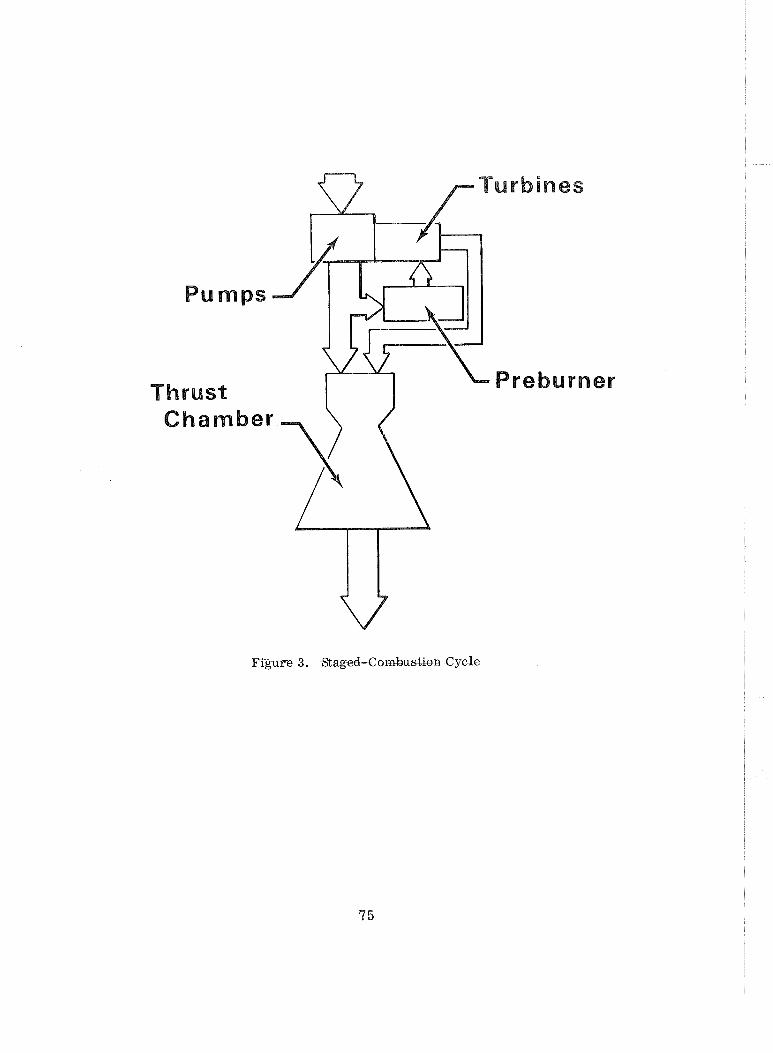
The staged combustion cycle shown in figure 3 has several critical per-
formance parameters that must be controlled to obtain the desired specific
impulse with a minimum engine weight. Each of these parameters has an
established limit that must not be exceeded. Repeated minor violations of
these limits can reduce engine life; major violations of these limits, even for
short time periods as in an engine transient, can produce component failures.
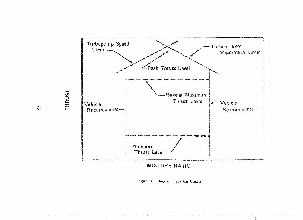
The engine operational boundaries a r e shown in figure 4.
The critical engine performance parameters include turbine inlet tempera-
ture, main.chamber wall temperature, turbopump speed and turbopump NPSH
margin. If the engine is designed for wide margins between the operational
boundaries and the established physical limits, this will result in additional
weight for a given engine performance. A low turbine inlet temperature re-
quires a higher preburner chamber pressure with additional turbopump and
chamber weight. A lower chamber wall temperature requires additional coolant,
which can reduce specific impulse by distorting the main chamber exit tempera-
ture profile. To restore specific impulse, a higher main chamber pressure and
chamber weight is required. Additional main turbopump NPSH margin results
in either: larger low speed inducers to provide additional main turbopump inlet
pressure, or a reduction in speed of the main turbopumps. For the same dis-
charge pressures the turbopump impeller diameters and turbopump weight will
increase. Efficient engine design, therefore, dictates that the engine operate
close to the performance parameter limits.
An engine designed to operate close to limits is sensitive to changes in
inlet conditions or degradations in component performance. The engine will be
exposed to variations in inlet pressure and temperature, which will affect turbo-
pump NPSH margin and, unless accounted for, will affect such critical engine
parameters a s turbine inlet temperature and main chamber temperature.
Gradual degradations in component performance may be encountered for a long-
life engine, or minor component malfunctions may produce step changes in
performance. Unless wide steady state operating margins a re provided to
account for tbese changes and the weight penalty accepted, a closed loop control
is required. A closed loop control that senses selected engine parameters not
only protects the engine from steady state environmental change and degradations
in component performance, but can also provide protection during transient
operation.

Open loop influence factors will differ slightly for each staged combustion
engine arrangement but typically, turbine temperature will change approximately
35 OR for a 1.0 OR change in fuel temperature and 50"R for 100 psi change in oxi-
dizer supply pressure. This is significant if the engine is running at the maximum
thrust and maximum allowable turbine temperature where it is life limited by
turbine creep. If the engine is operated at this power point with a 25 "R over-
temperature it will last approximately one-half of its design life.

11. APPROACH TO CONTROL SYSTEM DEVELOPMENT
A. Selection of Valve Locations
To determine the best control arrangement for a given engine, the valves
a r e first identified as power controls or load controls. Power controls modulate
power delivered by the turbines and load controls modulate the power required
to drive the pumps. Power controls can be further subdivided into variable
area turbines and turbine throttles. For each general category the best valve
location is selected primarily by i ts effect on specific impulse. Then a min-
imum number of valves is added until the combination can modulate the engine
over the desired thrust and mixture ratio range. A fairly complete steady-state
thermodynamic model of the engine is required in this analysis for the results
to be meaningful in terms of engine performance. For the case studied here,
the model required 225,000 bytes of core storage in an IBM-360 computer.
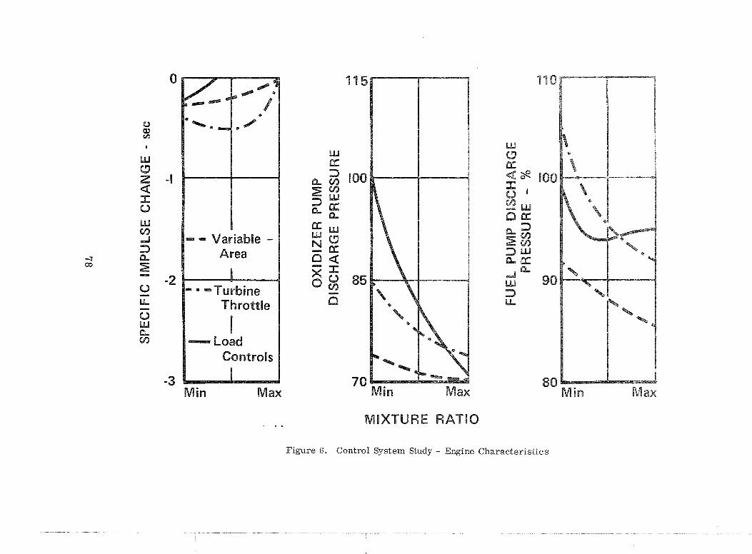
Figure 5 shows the best combination identified in each category and fig-
u re 6 shows the typical performance trade-offs that must be considered in
the selection of category. The choice here is the load controls combination
based on minimum impulse penalty i f the pump speed and turbine temperature
boundaries a r e acceptable.
B. Dynamic Analysis
A parallel study must also be conducted to evaluate the dynamic require-
ments the control system must satisfy. As shown in figure 7, the steady-state
performance studies and the dynamic analysis both influence the engine design
and arrangement. Application of the three dynamic modeling methods will be
necessary to properly assess the control performance. An analog model, a
digital dynamic model and finally a hybrid model will be required. The im-
portance of dynamic evaluation can be visualized by considering figure 8,
which shows the typical response characteristics of the engine to a thrust
command (2.8 cps). For a valve to reasonably control any loop within the en-
gine, its response should be approximately 5 times as fast or 14 cps. For a
control to track and modulate this valve position, its response should be ap-
proximately 5 times a s fast as the valve, or 70 cps. The basic engine thrust
response appears slow, primarily because of propellant compressibility in the
heat exchangers; however, inner loops of the engine are extremely fast. In com-
parison, a turbojet engine with similar control requirements, has approximately
15 times the SSME rotor inertia and only 40% of the steady-state turbine power,
and is , therefore, slower in response and easier to control.
In formulating the englne dynamic simulations each component must be
described in sufficient mathematical detail to define its time-dependent character
in terms of hydrodynamic and thermodynamic performance, and its time-dependent
relation to adjacent components. This constitutes the digital dynamic model used
for accurate analysis. A simpler analog model is also constructed, which
represents components with non-linear partial derivatives, and is used for
initial control system evaluation. With these tools available, a preliminary
selection of the control elements (sensors, actuators and control computer
logic) is made and a dynamic model is constructed. This control simulation i s
married to the appropriate engine model and evaluation of control modes can
begin. Because the primary function of the control system is to protect the
engine components, the system is evolved until adequate engine protection is
afforded under all steady-state and transient conditions.
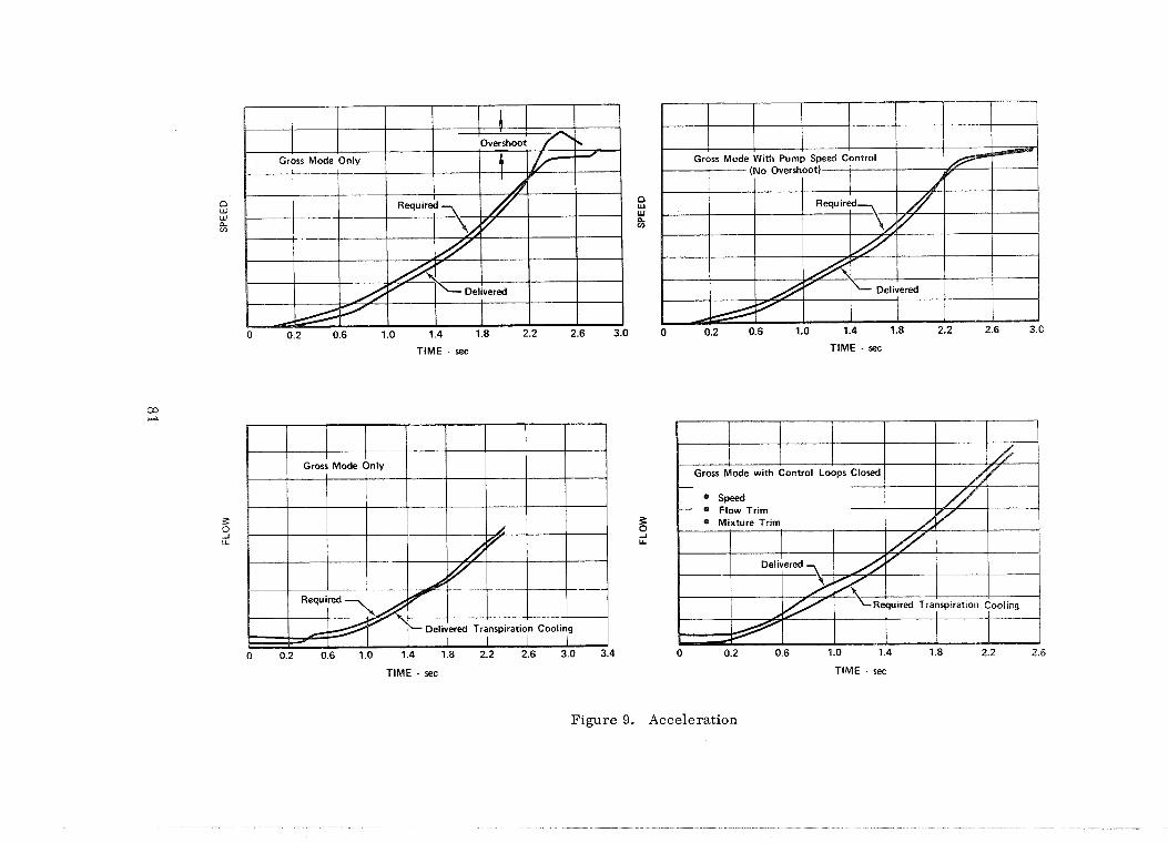
Typical problems and solutions are evaluated as shown in figure 9 where
speed overshoot and a cooling margin deficiency are identified in the open-loop
"gross mode" of control and are corrected by addition of the feedback loops.
C. Logic Mode
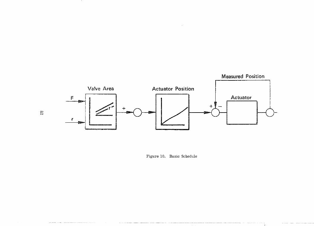
A potential logic mode for the SSME control consists of a basic open loop
scheduled system, with supervisory trim for precision and overrides for fail-
ure protection. The basic open loop system runs the engine through its normal
operating range with an absolute minimum dependence on measurements. The
propellant modulating elements of the engine are moved in response to vehicle
requests in accordance with a predetermined schedule of effective flow area
as a function of the requested power o r mixture ratio. Dynamic compensation
is accomplished in this system by directly relating flow area change with
time (rate control). Information to establish these schedules and rate limits
is obtained from prior analysis and confirmed by engine and valve test data.
The schedules are stored in the digital control permanent memory. A typical
basic schedule control loop is shown in figure 10.

A secondary mode of control is the supervisory, or limited authority tr im
function that employs some process measurements for its operation. This mode
improves thrust and mixture ratio precision by sensing engine parameters such
as total flow or flow ratio and trimming the basic control to within the allow-
able e r ro r limits. A typical supervisory trim control loop is shown in fig-
ure 11.
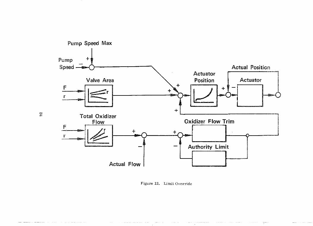
While the primary function of the control system i s to protect the engine
during steady-state and transient operation, an important secondary function i s
to protect the engine against the effects of deterioration of any component part
of the engine o r control system. Critical engine parameters must be monitored
to keep the engine within its design operating limits even though an unanticipated
environmental change o r a component malfunction has changed the basic engine
characteristics so that the predetermined schedules are no longer valid. A
limit override system senses the critical engine parameters and functions only
when an established limit has been exceeded. A typical limit override system
is shown in figure 12.
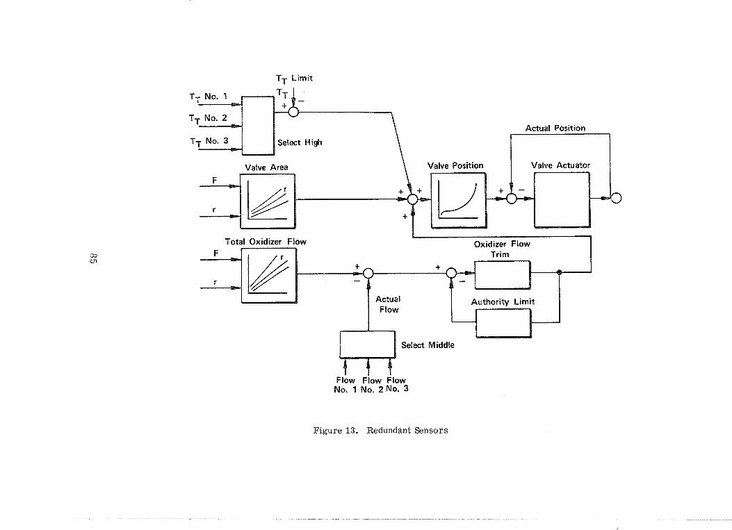
Redundancy in sensing elements with voting logic to select the sensor which
is functioning properly can reduce the effect of sensor malfunction. Typical r e -
dundant sensor inputs are shown in figure 13.
Safety and reliability must be considered in the control system arrange-
ment. The basic control mode should permit safe engine operation with reduced
accuracy after loss of the supervisory tr im system. The supervisory tr im system
should provide protection from the effects of performance degradation of engine
components which alter the desired predetermined valve schedules. In addition,
the redundant sensors and electronic control logic, employing self test techniques,
can assure the required reliability levels and confidence.
Computer Configuration
Hydromechanical and electronic configurations were considered for the
Space Shuttle Engine Control Unit (ECU). Hydromechanical control has been
adequate on turbojet engines and on a development model of the P&WA RLlO
throttling rocket engine but the requirement for improved engine performance
and the acceptance of "fly-by-wire" vehicle controls has accelerated the intro-
duction of electronic controls. Fortunately, major advances in solid state
electronic equipment have made the change possible at this time. P&WA is
currently applying engine-mounted electronic controls to gas turbine engines
under development; many thousands of hours of operational experience will
be accumulated in these programs. Solutions to the environmental problems
obtained in these programs will be available to supplement the SSME control
design and later development. Hydromechanical control applications for the
SSME are handicapped by the lack of a suitable working fluid; the engine
propellants are compressible and their properties vary over the engine opera-
ting range, introducing inaccuracy in a hydromechanical computer. The
addition of a third fluid as a working medium necessitates careful conditioning
to maintain properties and prevent freezing during engine tanking and hold
operations. Environmental conditioning can be accomplished for electronic
controls and the desired computation precision can be attained. The electronic
control interfaces readily with the vehicle and connects easily with remotely
located valve actuators. Based on these considerations for precision, environ-
ment, and compatibility with interface commands, an electronic engine command
unit i s best suited for the SSME.
Engine-mounting the engine command unit not only simplifies the engine/
vehicle interface but provides a special-purpose computer dedicated solely to
engine protection. This i s an important safety consideration for manned systems
as outlined in a paper by Operations Research Incorporated. Seven safety
principles were outlined and seem appropriate:
e Separate vital functions
Isolate vital equipment
e Employ fail-safe bias
e Design for serial independence
e Employ positive sequences
r Design for consistent behavior
e, Design for physical strength
These considerations should be applied in the concepts for design, pro-
duction and operation of the SSME control system.

111. ENGINE CHECKOUT AND DIAGNOSIS
A prime goal in the space shuttle i s economy. The airlines have found
that this requires high utilization of a s~nall fleet through efficient checkout
and maintenance. Automated on-board checkout and recording systems min-
imize the need for groundbased special-test equipment and their associated
maintenmce and reliability problems. An operational readiness signal will
indicate that the engine can s t a r t and accelerate to any thrust level. The
engine irdet conditions will be measured and compared to limits stored in the
control.
The vehicle operational readiness checks will include self test of the
control. If all systems a re within the limits, a signal will be provided to the
vehicle. If any parameter i s out of limits, i t can be identified to the vehicle.
These checks will be made prior to s tar t .
Parameters presently included in the operational readiness check are:
1. Electical Power
2. Control Operation (Self Test Program)
3. Helium System Pres su re
4. Propellant Inlet Conditions
5. Main Turbopump Housing Temperature
The sensors and control logic required for engine control and protection
also provides most, if not all the information which should be monitored for
engine performance assessment, check-out, diagnosis and malfunction isolation.
The availability of this information i s evident in figure 14 which shows one of
the control loops in block diagram form. Uncorrected e r r o r signals which per -
s i s t after a normal transient a re indicative of a system fault. An uncorrected
t r im e r r o r signal indicates that the engine component characteristics have
degraded beyond the capacity of the limited authority t r i m loop. An uncorrected
valve position e r r o r indicates a malfunction in the valve o r actuator. An active
override signal denotes that a major change in component characteristics has
occurred. Signals a re also available from the sensor and voting logic networks.
Since i t i s not desirable to hot f i re the SSME for ground checks, illflight
data recording and telemetry of available parameters is most important to ex-
pedite the maintenance turnaround. Interrogation and multiplexing procedures

for the monitored parameters must be coordinated with the vehicle to assure
that adequate vehicle computer memory capacity is available and that fault
indications are properly assessed by the vehicle for corrective action.
Malfunctions may be classified as to effect on engine and vehicle operation.
Failure Type Effect on Engine
Failure of a component None which has a redundant backup
Vehicle Action Required
Identify for ground maintenance
Failure of a component Reduced engine Assess effects on requiring a switch to precision and mission a backup control mode reliability
Degradation of a sub- Reduced engine thrust Assess effects on system requiring over- mission. Minor t r im ride tr im compensation in thrust
Failure of a subsystem Engine shutdown Assess effects on requiring advance to mission. Major tr im shutdown compensation in thrust
and possibly gimbal angle
The following signals are being considered for monitoring and recording
in the vehicle.
1. Uncorrected Valve Position Error Signals
2. Uncorrected Flow o r Chamber Pressure Error
3. Uncorrected Mixture Ratio Er ro r
4. Operation of backup control modes
5. Control system override signals
a. Turbopump speeds
b. Turbopump vibration
c. Turbopump NPSP
d. Turbine discharge temperatures
e. Nozzle coolant flow
Engine monitoring during preflight and flight operation can provide the
data necessary to identify failed Line Replaceable Units and schedule maintenance
activity.
IV. SENSOR TECHNOLOGY
Although basic schedules for the SSME control components will be pre-
determined and scheduled as open loop, supervisory tr im systems for precise
thrust and mixture ratio control, and overrides for engine protection are
planned and sensors are used in these control loops. The supervisory t r im
loops will require propellant flow o r chamber pressure measurement; override
loops utilize turbine exit temperature, turbopump speeds and some engine
pressure measurements. Sensor accuracy will be confirmed by calibrations
compared to the reference standards. The precision and accuracy of the
reference standards, the engine t r im procedure for thrust and mixture ratio
and the precision of remaining system components will define a precision
band for engine mounted sensor elements. In addition, these sensors should
not introduce biases which are a function of the operating environment and
result in an output shift. The sensor elements should be stable with ambient
temperature changes, vibration, acoustic noise, varying ambient pressure,
G loads, and changes in attitude.
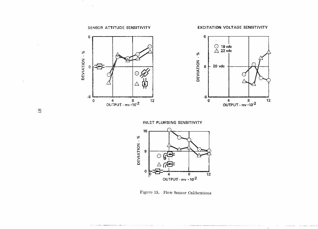
Propellant flow measurement must be made on a mass basis to account
for range in propellant inlet conditions encountered on the SSME. In lieu of a
pure mass flow measurement system, density must be calculated from addi-
tional pressure and temperature measurements. Successful development of
a pure mass flow measurement device.for the SSME would result in an overall
system improvement. Some of the problems encountered with typical flow
measurement devices are illustrated in figure 15 where the effects of installa-
tion on sensor output are shown.
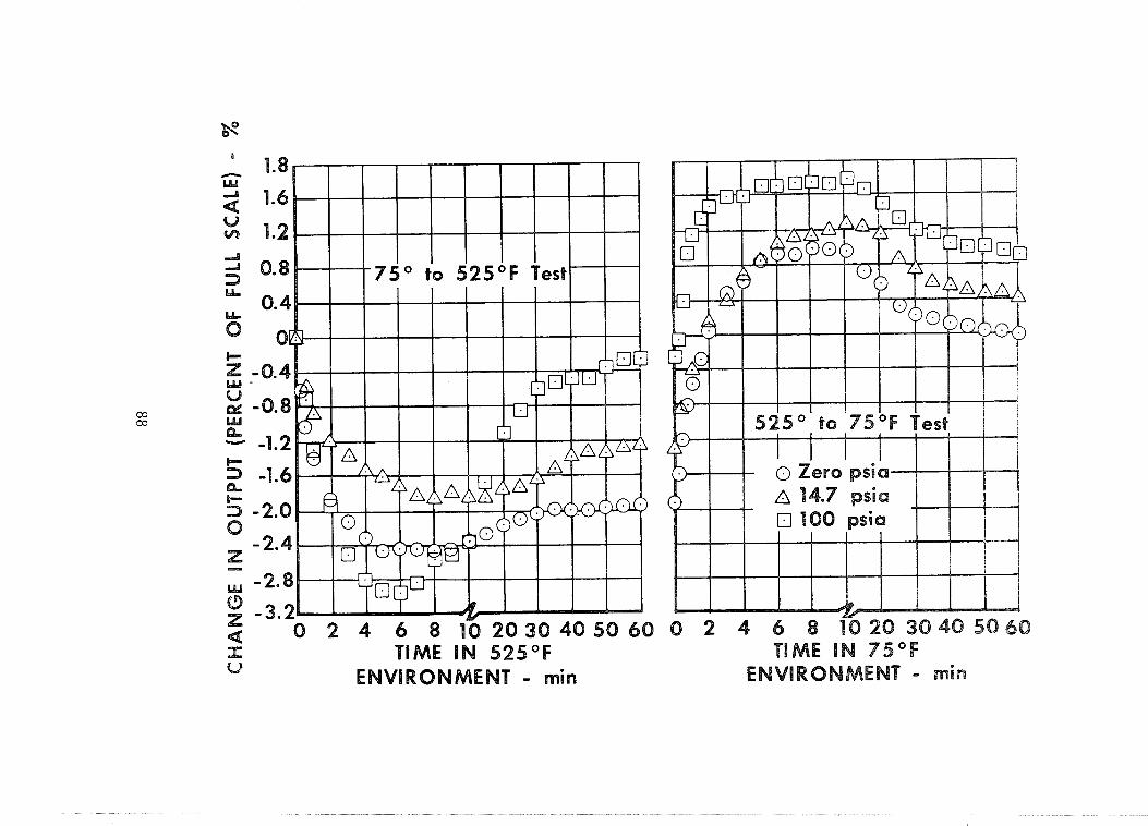
Pressure sensors for the SSME control will probably be of the diffused
strain gage o r deposited strain gage type. These devices are precise when
used in a reasonable environment. Acceptable steady-state temperature
compensation methods are available but we have found that a change in output
will be experienced for substantial time after an ambient temperature change.
Typical test results are shown in figure 16. The calibration results are shown
as percent deviation in output signal from the signal obtained in a standard
setup. A controlled environment for the strain gage can be added but it would
be better if a thermally insensitive instrument could be developed.
Turbine temperature i s an excellent parameter to use for engine protection
and diagnosis. Chrome1 Alumel therinocouples will probably be used for this
application but we are continually searching for more precise and reliable
devices. One candidate i s the infrared sensor which i s now being tested for
application to gas turbine engine blade temperature measurement. However,
this sensor requires control of the environment, and a window access through
the high pressure burner will be difficult to produce. Another candidate i s the
acoustic thermometer which measures temperature with a sonar technique.
Some cyclic endurance test results are shown in figure 17 that indicate a re-
peatability problem in the unit tested, and a drift in output with time. Post-test
inspection of the sample revealed evidence of oxidation which may have caused
the drift, perhaps this characteristic can be used to assess turbine life.
The performance, reliability and maintenance goals for the Space Shuttle
Main Engine place demanding performance requirements on the engine sensors.
To assure that these sensors will perform accurately and reliably in the SSME
environment, further technological development and thorough environmental
testing are required.
The technology for successful development of the §§ME control system,
checkout and diagnosis systems is presently available in most areas. Existing
techniques for development of control system logic modes through dynamic
analysis have been proved effective. The engine control system design will
require thorough dynamic evaluation for application to the SSME . Extensive
coordination between the engine, vehicle, and operational personnel will be
required to formulate effective engine checkout and diagnosis procedures.
Advances in technology for process sensors a re needed to improve reliability,
reduce sensitivity to environmental changes, and provide the confidence levels
necessary for space shuttle applications.
VI. REFERENCES
1. Cornell, Merrill E; , Systems, AIAA Paper Number 67-937, October 23, 1967, Operations
Research Incorporated.
2. Hill, L. J. , K. Urbach, Implications of an Integrated Electronics
System in Space Shuttle Operations, AIAA Paper Number 70-257,
February 4, 1970, Lockheed Missiles and Space Company.
3. Kirchnir, Englebert, Checkout After Apollo, Space/Aeronautics,
April, 1970.
4. McCall, J . C., F. Hudson, Integrated Electronics System for Space
Shuttle, AIAA Paper Number 70-261, February 4, 1970, International
Business Machines Corporation.
5. Przybylko, S. J. , Criteria for a Turbine Engine Control System
Development Model, Technical Memorandum APTA-TM-69-13,
June 1969, Turbine Engine Division-Air Force Aero Propulsion
Laboratory-Air Force Systems Command.
6. Stewart, F. M. , R. L. Wetherington, Space Shuttle Main Propulsion,
AAS Paper No. 70-044, June 7, 1970. Marshall Space Flight Center.
7. Warwick, T. R. , Helicopter Engine Dynamic Analysis, American
Helicopter Society Paper No. 332, May 14, 1969, Pratt & Whitney
Aircraft.


Figrre 3. *aged-Combustion Cycle


TlME - sec
0 0.2 0.6 1.0 1.4 1.8 2.2 2.6 3.0
TlME - sec
TlME - sec
Figure 9. Acceleration
TlME - sec


0
0
0
0
0
0
0
0
0
e
N 30 - N
OI
IV
IA
~~
~
~i
-
I