Technology Focus Electronics/Computers - … · Technology Focus Electronics/Computers Software...
40
Technology Focus Electronics/Computers Software Materials Mechanics/Machinery Manufacturing Bio-Medical Physical Sciences Information Sciences Books and Reports 05-07 May 2007 https://ntrs.nasa.gov/search.jsp?R=20090041630 2018-08-20T09:01:22+00:00Z
Transcript of Technology Focus Electronics/Computers - … · Technology Focus Electronics/Computers Software...

Technology Focus
Electronics/Computers
Software
Materials
Mechanics/Machinery
Manufacturing
Bio-Medical
Physical Sciences
Information Sciences
Books and Reports
05-07 May 2007
https://ntrs.nasa.gov/search.jsp?R=20090041630 2018-08-20T09:01:22+00:00Z

NASA Tech Briefs, May 2007 1
INTRODUCTIONTech Briefs are short announcements of innovations originating from research and develop-
ment activities of the National Aeronautics and Space Administration. They emphasizeinformation considered likely to be transferable across industrial, regional, or disciplinary linesand are issued to encourage commercial application.
Availability of NASA Tech Briefs and TSPsRequests for individual Tech Briefs or for Technical Support Packages (TSPs) announced herein shouldbe addressed to
National Technology Transfer CenterTelephone No. (800) 678-6882 or via World Wide Web at www.nttc.edu
Please reference the control numbers appearing at the end of each Tech Brief. Information on NASA’s Innovative Partnerships Program (IPP), its documents, and services is also available at the same facility oron the World Wide Web at http://ipp.nasa.gov.
Innovative Partnerships Offices are located at NASA field centers to provide technology-transfer access toindustrial users. Inquiries can be made by contacting NASA field centers listed below.
Ames Research CenterLisa L. Lockyer(650) [email protected]
Dryden Flight Research CenterGregory Poteat(661) [email protected]
Glenn Research CenterKathy Needham(216) [email protected]
Goddard Space Flight CenterNona Cheeks(301) [email protected]
Jet Propulsion LaboratoryKen Wolfenbarger(818) [email protected]
Johnson Space CenterMichele Brekke(281) [email protected]
Kennedy Space CenterDavid R. Makufka(321) [email protected]
Langley Research CenterMartin Waszak(757) [email protected]
Marshall Space Flight CenterJim Dowdy(256) [email protected]
Stennis Space CenterJohn Bailey(228) 688-1660 [email protected]
Carl Ray, Program ExecutiveSmall Business Innovation Research (SBIR) & Small Business Technology Transfer (STTR) Programs(202) [email protected]
Doug Comstock, DirectorInnovative Partnerships Program Office(202) [email protected]
NASA Field Centers and Program Offices

5 Technology Focus: Sensors5 Noise-Canceling Helmet Audio System
6 Program Analyzes Spacecraft/Ground Radio Links
6 Two-Way Communication Using RFID Equipmentand Techniques
7 Six-Message Electromechanical Display System
9 Electronics/Computers9 Scanning Terahertz Heterodyne Imaging Systems
10 Master Clock and Time-Signal-DistributionSystem
11 Synchronous Phase-Resolving Flash RangeImaging
12 Integrated Radial Probe Transition From MMIC toWaveguide
13 Bar-Code System for a Microbiological Laboratory
14 MMIC Amplifier Produces Gain of 10 dB at 235 GHz
15 Mapping Nearby Terrain in 3D by Use of a Grid ofLaser Spots
15 Digital Beam Deflectors Based Partly on LiquidCrystals
16 Narrow-Band WGM Optical Filters With TunableFSRs
19 Software19 Better Finite-Element Analysis of Composite Shell
Structures
19 Computing Spacecraft-Pointing Vectors for LimbTracking
19 Enhanced Master Controller Unit Tester
19 Rover Graphical Simulator
21 Materials21 Increasing Durability of Flame-Sprayed Strain
Gauges
22 Multifunctional, High-TemperatureNanocomposites
23 Multilayer Impregnated Fibrous ThermalInsulation Tiles
25 Manufacturing & Prototyping25 Radiation-Shielding Polymer/Soil Composites
25 Film/Adhesive Processing Module for Fiber-Placement Processing of Composites
26 Fabrication of Submillimeter Axisymmetric OpticalComponents
27 Physical Sciences27 Electrochemical Disposal of Hydrazines in Water
28 Statistical Model of Evaporating MulticomponentFuel Drops
29 Resistively Heated SiC Nozzle for GeneratingMolecular Beams
29 Compact Packaging of Photonic Millimeter-WaveReceiver
30 Diffractive Combiner of Single-Mode Pump Laser-Diode Beams
31 Wide-Band, High-Quantum-EfficiencyPhotodetector
33 Information Sciences33 A Robustly Stabilizing Model Predictive Control
Algorithm
33 Modeling Evaporation of Drops of DifferentKerosenes
35 Books & Reports35 Development of Vapor-Phase Catalytic Ammonia
Removal System
35 Several Developments in Space Tethers
35 Design Concept for a Nuclear Reactor-PoweredMars Rover
35 Formation-Initialization Algorithm for NSpacecraft
36 DNSs of Multicomponent Gaseous and Drop-Laden Mixing Layers Achieving Transition toTurbulence
05-07 May 2007
NASA Tech Briefs, May 2007 3
This document was prepared under the sponsorship of the National Aeronautics and Space Administration. Neither the United States Govern-ment nor any person acting on behalf of the United States Government assumes any liability resulting from the use of the information containedin this document, or warrants that such use will be free from privately owned rights.

NASA Tech Briefs, May 2007 5
Technology Focus: Communications
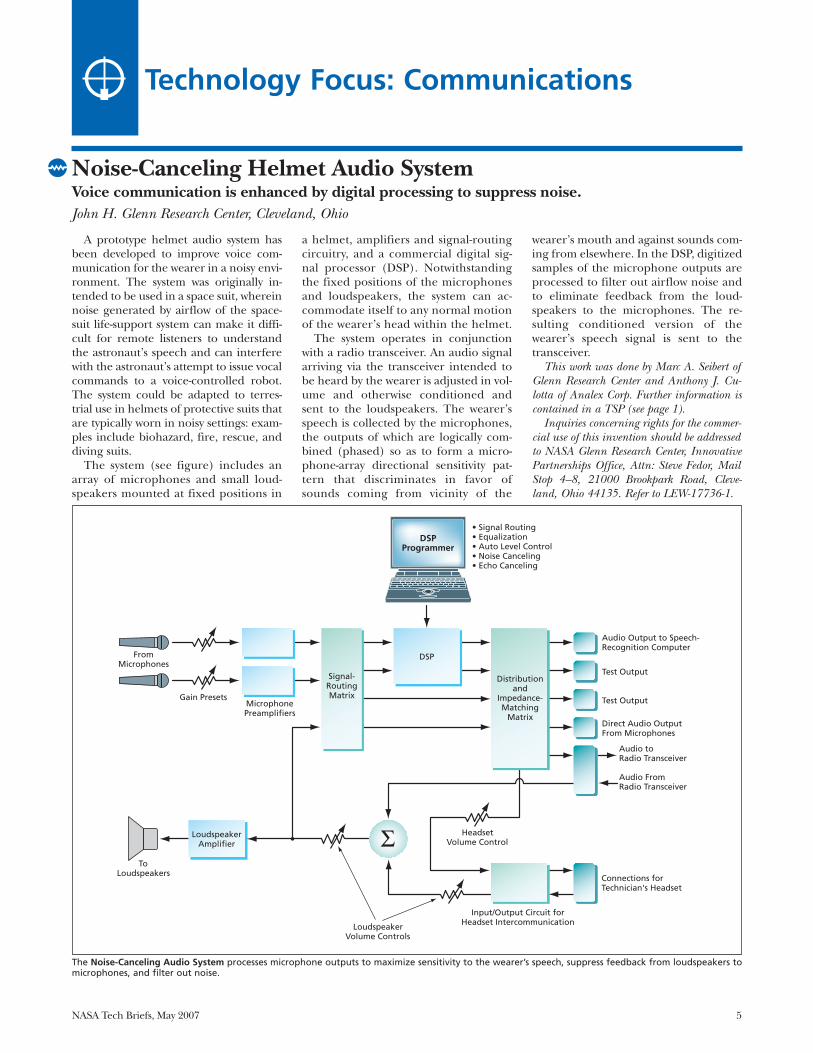
A prototype helmet audio system hasbeen developed to improve voice com-munication for the wearer in a noisy envi-ronment. The system was originally in-tended to be used in a space suit, whereinnoise generated by airflow of the space-suit life-support system can make it diffi-cult for remote listeners to understandthe astronaut’s speech and can interferewith the astronaut’s attempt to issue vocalcommands to a voice-controlled robot.The system could be adapted to terres-trial use in helmets of protective suits thatare typically worn in noisy settings: exam-ples include biohazard, fire, rescue, anddiving suits.
The system (see figure) includes anarray of microphones and small loud-speakers mounted at fixed positions in
a helmet, amplifiers and signal-routingcircuitry, and a commercial digital sig-nal processor (DSP). Notwithstandingthe fixed positions of the microphonesand loudspeakers, the system can ac-commodate itself to any normal motionof the wearer’s head within the helmet.
The system operates in conjunctionwith a radio transceiver. An audio signalarriving via the transceiver intended tobe heard by the wearer is adjusted in vol-ume and otherwise conditioned andsent to the loudspeakers. The wearer’sspeech is collected by the microphones,the outputs of which are logically com-bined (phased) so as to form a micro-phone-array directional sensitivity pat-tern that discriminates in favor ofsounds coming from vicinity of the
wearer’s mouth and against sounds com-ing from elsewhere. In the DSP, digitizedsamples of the microphone outputs areprocessed to filter out airflow noise andto eliminate feedback from the loud-speakers to the microphones. The re-sulting conditioned version of thewearer’s speech signal is sent to thetransceiver.
This work was done by Marc A. Seibert ofGlenn Research Center and Anthony J. Cu-lotta of Analex Corp. Further information iscontained in a TSP (see page 1).
Inquiries concerning rights for the commer-cial use of this invention should be addressedto NASA Glenn Research Center, InnovativePartnerships Office, Attn: Steve Fedor, MailStop 4–8, 21000 Brookpark Road, Cleve-land, Ohio 44135. Refer to LEW-17736-1.
Noise-Canceling Helmet Audio System Voice communication is enhanced by digital processing to suppress noise. John H. Glenn Research Center, Cleveland, Ohio
DSP Programmer
• Signal Routing • Equalization • Auto Level Control • Noise Canceling • Echo Canceling
Microphone Preamplifiers
Signal- Routing Matrix
DSP
Distribution and
Impedance- Matching
Matrix
Audio Output to Speech-Recognition Computer
Direct Audio Output From Microphones
Audio to Radio Transceiver
Audio From Radio Transceiver
Connections for Technician's Headset
Input/Output Circuit for Headset Intercommunication Loudspeaker
Volume Controls
Headset Volume Control
Loudspeaker Amplifier
To Loudspeakers
Test Output
Test Output Gain Presets
From Microphones
Σ
The Noise-Canceling Audio System processes microphone outputs to maximize sensitivity to the wearer’s speech, suppress feedback from loudspeakers tomicrophones, and filter out noise.
6 NASA Tech Briefs, May 2007
Program Analyzes Spacecraft/Ground Radio LinksNASA’s Jet Propulsion Laboratory, Pasadena, California
Two-Way Communication Using RFID Equipment and TechniquesDynamic data could be exchanged, in addition to conventional static RFID data.NASA’s Jet Propulsion Laboratory, Pasadena, California
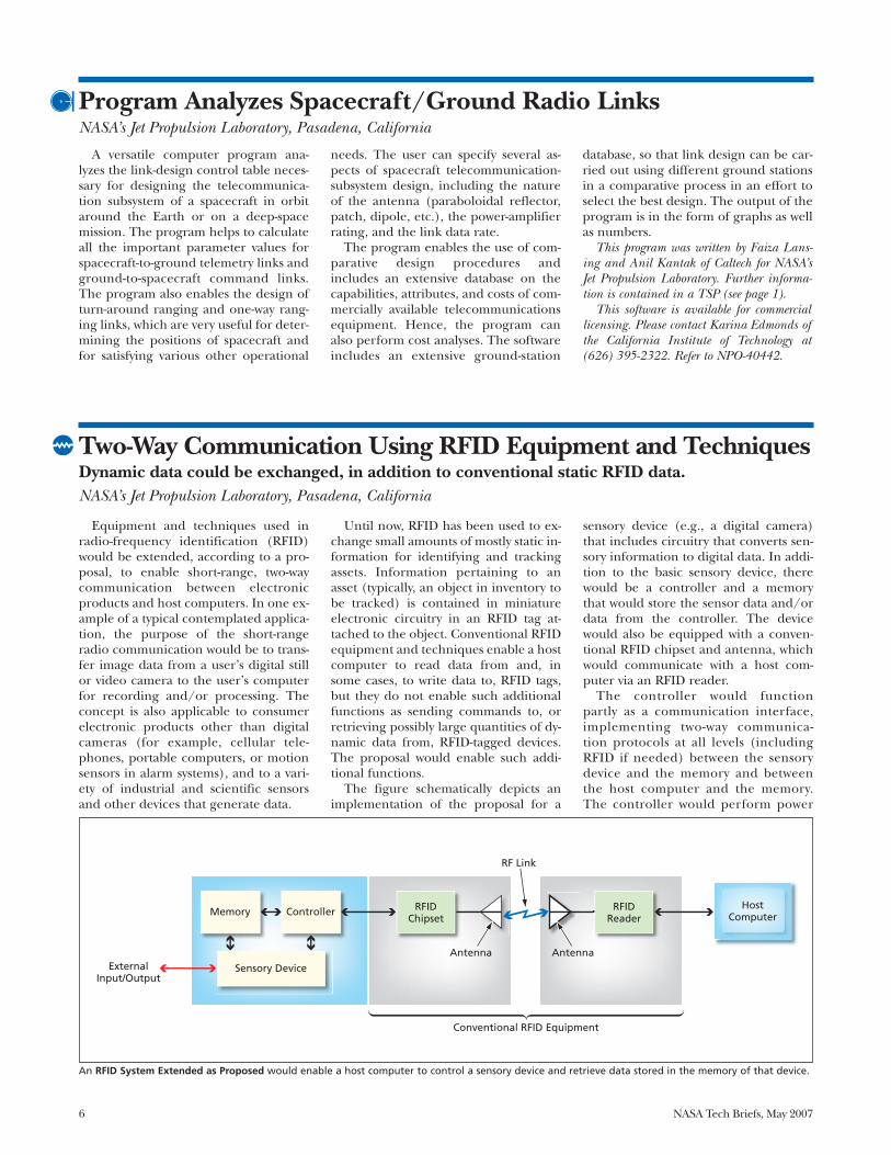
Equipment and techniques used inradio-frequency identification (RFID)would be extended, according to a pro-posal, to enable short-range, two-waycommunication between electronicproducts and host computers. In one ex-ample of a typical contemplated applica-tion, the purpose of the short-rangeradio communication would be to trans-fer image data from a user’s digital stillor video camera to the user’s computerfor recording and/or processing. Theconcept is also applicable to consumerelectronic products other than digitalcameras (for example, cellular tele-phones, portable computers, or motionsensors in alarm systems), and to a vari-ety of industrial and scientific sensorsand other devices that generate data.
Until now, RFID has been used to ex-change small amounts of mostly static in-formation for identifying and trackingassets. Information pertaining to anasset (typically, an object in inventory tobe tracked) is contained in miniatureelectronic circuitry in an RFID tag at-tached to the object. Conventional RFIDequipment and techniques enable a hostcomputer to read data from and, insome cases, to write data to, RFID tags,but they do not enable such additionalfunctions as sending commands to, orretrieving possibly large quantities of dy-namic data from, RFID-tagged devices.The proposal would enable such addi-tional functions.
The figure schematically depicts animplementation of the proposal for a
sensory device (e.g., a digital camera)that includes circuitry that converts sen-sory information to digital data. In addi-tion to the basic sensory device, therewould be a controller and a memorythat would store the sensor data and/ordata from the controller. The devicewould also be equipped with a conven-tional RFID chipset and antenna, whichwould communicate with a host com-puter via an RFID reader.
The controller would functionpartly as a communication interface,implementing two-way communica-tion protocols at all levels (includingRFID if needed) between the sensorydevice and the memory and betweenthe host computer and the memory.The controller would perform power
Memory
External Input/Output
Controller
Sensory Device
RFID Chipset
Antenna Antenna
RFID Reader
RF Link
Conventional RFID Equipment
Host Computer
A versatile computer program ana-lyzes the link-design control table neces-sary for designing the telecommunica-tion subsystem of a spacecraft in orbitaround the Earth or on a deep-spacemission. The program helps to calculateall the important parameter values forspacecraft-to-ground telemetry links andground-to-spacecraft command links.The program also enables the design ofturn-around ranging and one-way rang-ing links, which are very useful for deter-mining the positions of spacecraft andfor satisfying various other operational
needs. The user can specify several as-pects of spacecraft telecommunication-subsystem design, including the natureof the antenna (paraboloidal reflector,patch, dipole, etc.), the power-amplifierrating, and the link data rate.
The program enables the use of com-parative design procedures and includes an extensive database on the capabilities, attributes, and costs of com-mercially available telecommunicationsequipment. Hence, the program canalso perform cost analyses. The softwareincludes an extensive ground-station
database, so that link design can be car-ried out using different ground stationsin a comparative process in an effort toselect the best design. The output of theprogram is in the form of graphs as wellas numbers.
This program was written by Faiza Lans-ing and Anil Kantak of Caltech for NASA’sJet Propulsion Laboratory. Further informa-tion is contained in a TSP (see page 1).
This software is available for commerciallicensing. Please contact Karina Edmonds ofthe California Institute of Technology at(626) 395-2322. Refer to NPO-40442.
An RFID System Extended as Proposed would enable a host computer to control a sensory device and retrieve data stored in the memory of that device.
NASA Tech Briefs, May 2007 7
management and other tasks essentialto operation, and would encrypt dataif necessary.
The RFID chipset would handleRFID communications (including im-plementing RFID protocols in coopera-tion with the controller). As in ordinaryRFID tags, the RFID chipset would ac-cept RF power received via the antenna,convert the RF power to DC power, anddistribute the power both within itselfand to any other circuitry as needed.The RFID chipset would interact withthe controller to pass data from the sen-
sor memory to the host computerand/or to pass commands from thehost computer.
The host computer would control theRFID reader. The host computer wouldcontain application software and/orfirmware that would enable the user tocommunicate with the sensory deviceand process data received from the sen-sory device.
This work was done by Thomas Jedry andEric Archer of Caltech for NASA’s Jet Propul-sion Laboratory. Further information is con-tained in a TSP (see page 1).
In accordance with Public Law 96-517,the contractor has elected to retain title to thisinvention. Inquiries concerning rights for itscommercial use should be addressed to:
Innovative Technology Assets ManagementJPL
Mail Stop 202-2334800 Oak Grove DrivePasadena, CA 91109-8099(818) 354-2240E-mail: [email protected] to NPO-43144, volume and number
of this NASA Tech Briefs issue, and thepage number.
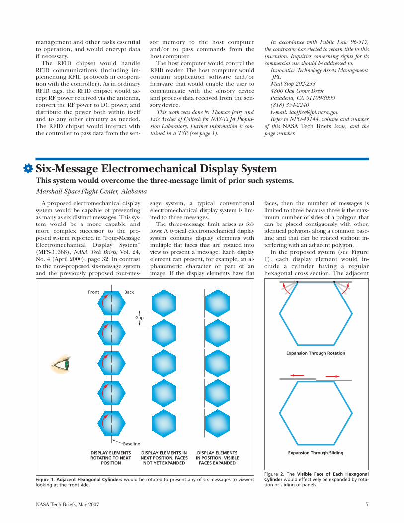
A proposed electromechanical displaysystem would be capable of presentingas many as six distinct messages. This sys-tem would be a more capable and more complex successor to the pro-posed system reported in “Four-MessageElectromechanical Display System”(MFS-31368), NASA Tech Briefs, Vol. 24,No. 4 (April 2000), page 32. In contrastto the now-proposed six-message systemand the previously proposed four-mes-
sage system, a typical conventionalelectromechanical display system is lim-ited to three messages.
The three-message limit arises as fol-lows: A typical electromechanical displaysystem contains display elements withmultiple flat faces that are rotated intoview to present a message. Each displayelement can present, for example, an al-phanumeric character or part of animage. If the display elements have flat
faces, then the number of messages islimited to three because three is the max-imum number of sides of a polygon thatcan be placed contiguously with other,identical polygons along a common base-line and that can be rotated without in-terfering with an adjacent polygon.
In the proposed system (see Figure1), each display element would in-clude a cylinder having a regularhexagonal cross section. The adjacent
Six-Message Electromechanical Display SystemThis system would overcome the three-message limit of prior such systems.Marshall Space Flight Center, Alabama
Baseline
DISPLAY ELEMENTS ROTATING TO NEXT
POSITION
DISPLAY ELEMENTS IN NEXT POSITION, FACES
NOT YET EXPANDED
DISPLAY ELEMENTS IN POSITION, VISIBLE
FACES EXPANDED
Front Back
Gap
Figure 1. Adjacent Hexagonal Cylinders would be rotated to present any of six messages to viewerslooking at the front side.
Expansion Through Rotation
Expansion Through Sliding
Figure 2. The Visible Face of Each HexagonalCylinder would effectively be expanded by rota-tion or sliding of panels.

8 NASA Tech Briefs, May 2007
elements would be positioned along abaseline with just enough room thateach element could rotate without in-terfering with an adjacent element. Asin the systems mentioned above, eachface of each element would representa portion of a message. Each elementcould be rotated to one of six equallyspaced angular positions to presentthe desired portion of one of six mes-sages. However, unlike in prior sys-tems, merely orienting the desired
faces to form a flat surface visible to in-tended viewers would not suffice topresent the message because therewould be large gaps between the facesof the aligned hexagons.
To enable filling of the gaps betweenthe visible aligned faces of adjacenthexagons, the affected portions of themessages would be placed on panels thatwould be rotated or slid to effectively ex-pand the visible faces to fill or nearly fillthe gaps (see Figure 2). After presenta-
tion of a message, panels would be re-tracted, restoring the hexagonal out-lines to enable rotation of the elementsto display the next message. Optionally,panels on both the front and the back ofthe display could be extended simulta-neously to present different front andback messages.
This work was done by Richard T.Howard of Marshall Space Flight Center.Further information is contained in a TSP(see page 1). Refer to MFS-31576-1.
NASA Tech Briefs, May 2007 9
Scanning terahertz heterodyne imag-ing systems are now at an early stage ofdevelopment. They were recently con-ceived as means of probing biologicalspecimens and samples of materials toobtain information complementary tothat obtainable from imaging systemsthat utilize other parts of the electro-magnetic spectrum (e.g., visible light orx rays). Emerging applications for scan-ning terahertz heterodyne imaging sys-tems include studies of terahertz con-trast mechanisms in biological samples,pump-probe excitation of phononmodes in liquids and solids, studies of ef-fects of terahertz irradiance on func-tions and forms of living cells, and stud-ies of spectral signatures indicative ofbinding and structures of protein mole-cules.
Scanning terahertz heterodyne imag-ing systems using continuous-wave (CW)radiation offer the wide dynamic rangesand high signal-to-noise ratios character-istic of narrow-band high-spectral-reso-lution systems. As such, they also invitecomparison with other terahertz imag-ing systems that utilize short-pulse time-domain spectroscopy (TDS), which isextremely powerful as a diagnostic tech-nique but typically involves limitations indynamic range and spectral resolution.One especially notable result of thesedifferences is that in wet tissues, tera-hertz TDS systems are limited to pene-tration depths of the order of microns,while terahertz heterodyne systems canreach depths of the order of millimeters.Because the capabilities afforded by theterahertz heterodyne concept are partlycomplementary to those afforded by theterahertz short-pulse TDS concept, im-aging systems based on these conceptscould be used as complements to eachother to obtain more information thancould be obtained by use of either sys-tem alone.
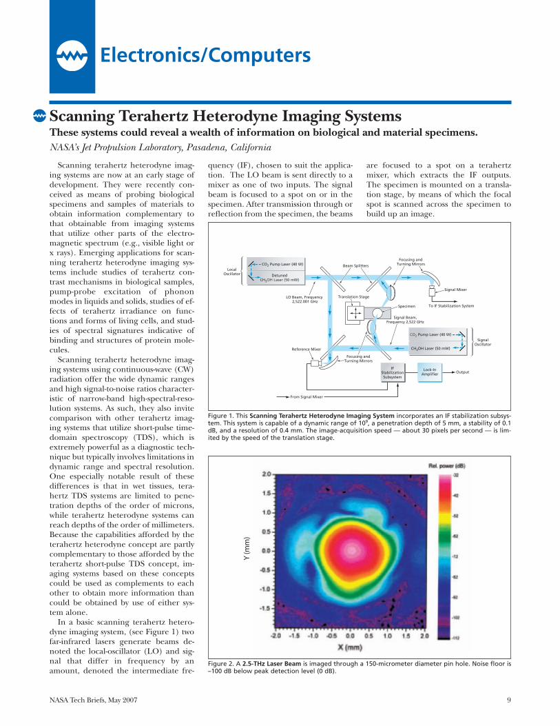
In a basic scanning terahertz hetero-dyne imaging system, (see Figure 1) twofar-infrared lasers generate beams de-noted the local-oscillator (LO) and sig-nal that differ in frequency by anamount, denoted the intermediate fre-
quency (IF), chosen to suit the applica-tion. The LO beam is sent directly to amixer as one of two inputs. The signalbeam is focused to a spot on or in thespecimen. After transmission through orreflection from the specimen, the beams
are focused to a spot on a terahertzmixer, which extracts the IF outputs.The specimen is mounted on a transla-tion stage, by means of which the focalspot is scanned across the specimen tobuild up an image.
Electronics/Computers
Scanning Terahertz Heterodyne Imaging SystemsThese systems could reveal a wealth of information on biological and material specimens.NASA’s Jet Propulsion Laboratory, Pasadena, California
Figure 2. A 2.5-THz Laser Beam is imaged through a 150-micrometer diameter pin hole. Noise floor is–100 dB below peak detection level (0 dB).
Figure 1. This Scanning Terahertz Heterodyne Imaging System incorporates an IF stabilization subsys-tem. This system is capable of a dynamic range of 109, a penetration depth of 5 mm, a stability of 0.1dB, and a resolution of 0.4 mm. The image-acquisition speed — about 30 pixels per second — is lim-ited by the speed of the translation stage.
10 NASA Tech Briefs, May 2007
The performance of the basic scan-ning terahertz heterodyne imaging sys-tem is limited by a number of factors,the most prominent one being fre-quency instability of the lasers. The fig-ure depicts a more complex prototypesystem that incorporates an IF stabiliza-tion subsystem that increases the achiev-able frequency stability and dynamicrange. This system utilizes two mixersdenoted the reference and signal mix-ers, and the signal from each laser is splitinto two beams denoted the referenceand signal beams. One of the lasers isslightly detuned so that their frequen-cies differ by an IF between 1 and 3MHz. The IF outputs of the two mixersare equal in frequency; however, theydiffer in amplitude and phase becauseof the loss and phase shift suffered bythe signal beam that passes through the
specimen and impinges on the signalmixer.
The IF output of the signal mixer be-comes one of two inputs to a thirdmixer that is part of the IF stabilizationsubsystem. In a fourth mixer that is alsopart of the IF stabilization subsystem,the IF output of the reference mixer ismixed with a stable 14.6-MHz oscillatorsignal, and the resulting signal be-comes the other input to the thirdmixer. The output of the third mixerand thus the output of the IF stabiliza-tion subsystem is a signal that has a sta-ble frequency of 14.6 MHz but exhibitsvariations in amplitude and phase ac-cording to the loss and phase shift ofthe signal beam passing through thespecimen. An improved system withand IF of 24 GHz has now been com-pleted with a dynamic range of 100 dB
(Figure 2), 100 pixels/second, andpenetration of 25 mm.
This work was done by Peter Siegel andRobert Dengler of Caltech for NASA’s JetPropulsion Laboratory. Further informationis contained in a TSP (see page 1).
In accordance with Public Law 96-517,the contractor has elected to retain title tothis invention. Inquiries concerning rightsfor its commercial use should be addressedto:
Innovative Technology Assets ManagementJPLMail Stop 202-2334800 Oak Grove DrivePasadena, CA 91109-8099(818) 354-2240E-mail: [email protected] to NPO-40474, volume and number
of this NASA Tech Briefs issue, and thepage number.
A timing system comprising an elec-tronic master clock and a subsystem fordistributing time signals from the masterclock to end users is undergoing devel-opment to satisfy anticipated timing re-quirements of NASA’s Deep Space Net-work (DSN) for the next 20 to 30 years.The developmental system is intendedto supplant the aging DSN frequencyand timing subsystem (FTS), which,while historically reliable, is complex,has limited distribution capacity and hasbecome increasingly difficult to operateand sustain. This system has a modular,flexible, expandable architecture that iseasier to operate and maintain than thepresent FTS. Replicas of this systemcould be useful in laboratories andother facilities in which there are strin-gent timing requirements that could in-clude requirements to distribute precisetime signals over long distances.
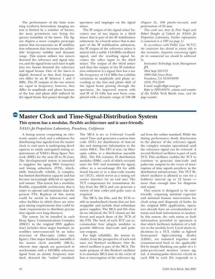
The system [to be installed in eachDeep Space Communications Complex(DSCC) in the original DSN applica-tion] includes three major hardware as-semblies interconnected by an infra-structure of fiber-optic cables (seefigure). One major hardware assembly isthe master clock assembly (MCA),wherein time signals are generated insynchronism with a 100-MHz referencesignal from an atomic frequency stan-dard, denoted the “online” standard.
The MCA is set to Universal Coordi-nated Time and generates a system timecode (STC) for distribution of time-of-day and timing-rate information to theentire DSCC. The STC is sent, via fiber-optic cables, to a distribution assembly(DA). The DA contains 10 distributionmodules (DMs), each of which reconsti-tutes the STC and transmits the signal,either to a second-stage DA for addi-tional fan-out or to a time-code transla-tor (TCT), which serves as a timing ref-erence interface for an end user. TheTCT compensates for transmission de-lays from the MCA and can generate avariety of time codes and pulse rates asrequired.
The MCA, the DAs, and the TCTs re-side in standardized chassis that are hot-swappable and include dual redundantpower supplies. The MCA and DA chas-sis are identical; the TCT chassis are dif-ferent and match those of the TCTs ofthe FTS. The back of each TCT can ac-commodate four plug-in modules toprovide different time-code and pulserate outputs.
For high reliability, the system in-cludes, from the perspective of each enduser, two flywheel oscillators. One fly-wheel oscillator is part of the MCA. Themain purpose of this flywheel oscillatoris to maintain MCA time in the event ofloss or interruption of the reference sig-
nal from the online standard. While thetiming performance slowly deterioratesin the absence of the reference signal,the complex remains operational untilthe reference signal can be restored. Asecond flywheel oscillator is part of eachTCT. This oscillator enables the TCT tocontinue to generate time-code andpulse-rate outputs in the event of inter-ruption of time signals anywhere in thedistribution infrastructure. The TCT fly-wheel oscillator is allowed to run for aholdover interval up to 12 hours —more than enough time for diagnosisand repair.
This system is designed to be user-friendly, requiring minimal expertiseand minimal human intervention forclock setup and diagnosis of faults. Inthe original DSN application, opera-tors already have an overabundance ofstatus and fault information to analyze.In this system, the only status or faultinformation provided to operators isthat which facilitates isolation of a fail-ure to the module level. Local alarm in-dications in a TCT, visible as lightedfront-panel light-emitting diodes(LEDs), are summed together andcommunicated back to the applicableDA by simply blanking one pulse of a 1-pulse-per-second monitor return sig-nal. A missing-pulse detector circuit ineach DM in each DA responds to a
Master Clock and Time-Signal-Distribution SystemThis system has a modular, flexible architecture and is user-friendly.NASA’s Jet Propulsion Laboratory, Pasadena, California
blanked pulse by turning on an LED inthe DM. Each DA chassis contains onealarm representing the summed alarmsof all 10 of its DMs. This alarm is passedfurther back up the hierarchy or col-lected by a status summary monitor
computer visible to operators. Withmodularity and simple “go/no-go”monitoring and alarm information, op-erators can maintain operations withlittle understanding of the nuances ofthe precise timing system.
This work was done by Robert Tjoelker,Malcolm Calhoun, Paul Kuhnle, RichardSydnor, and John Lauf of Caltech for NASA’sJet Propulsion Laboratory. Further informa-tion is contained in a TSP (see page 1).NPO-40851
NASA Tech Briefs, May 2007 11
UserInterface
Time-CodeGenerator
MCA
FlywheelOscillator
100-MHzReference Signal
DA
DA
TCT
TCT Signals for End User
Signals for End User
Signals for End User
Copper Cables
Fiber-Optic Cables
Signals for End User
TCT
DA
TCT
TCT
The Timing System consists of hardware modules interconnected by fiber-optic cables. This block diagram is a highly simplified representation: The realsystem has a more complex fan-out, with more modules, cables, and end users.
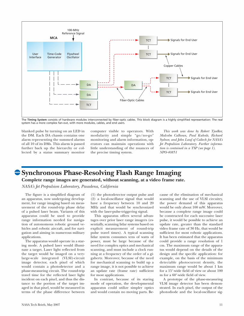
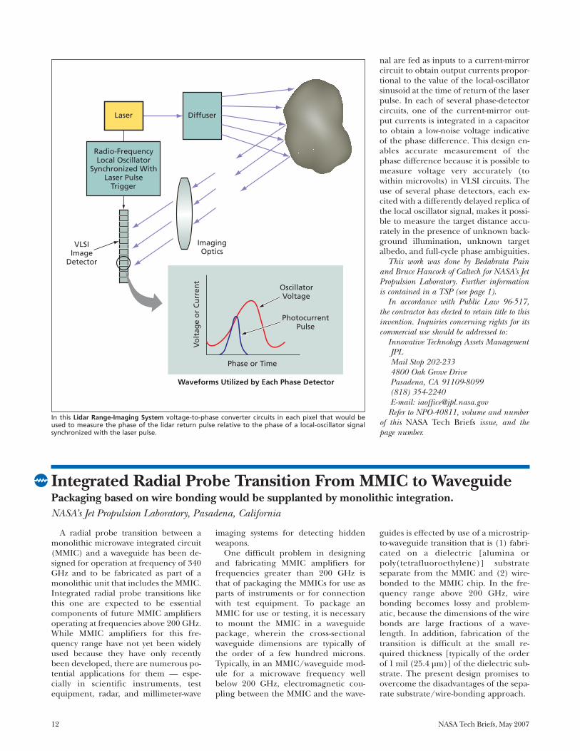
The figure is a simplified diagram ofan apparatus, now undergoing develop-ment, for range imaging based on meas-urement of the round-trip phase delayof a pulsed laser beam. Variants of thisapparatus could be used to providerange information needed for naviga-tion of autonomous robotic ground ve-hicles and robotic aircraft, and for navi-gation and aiming in numerous militaryapplications.
The apparatus would operate in a star-ing mode. A pulsed laser would illumi-nate a target. Laser light reflected fromthe target would be imaged on a very-large-scale integrated (VLSI)-circuitimage detector, each pixel of whichwould contain a photodetector and aphase-measuring circuit. The round-triptravel time for the reflected laser lightincident on each pixel, and thus the dis-tance to the portion of the target im-aged in that pixel, would be measured interms of the phase difference between
(1) the photodetector output pulse and(2) a local-oscillator signal that wouldhave a frequency between 10 and 20MHz and that would be synchronizedwith the laser-pulse-triggering signal.
This apparatus offers several advan-tages over prior laser range imagers (es-sentially, scanning lidar systems based onexplicit measurement of round-trippulse travel times). A typical scanninglidar system consumes tens of watts ofpower, must be large because of theneed for complex optics and mechanicalscanning, and must include a clock run-ning at a frequency of the order of a gi-gahertz. Moreover, because of the needfor mechanical scanning to build up arange image, it is not possible to achievean update rate (frame rate) sufficientfor most applications.
In contrast, because of its staringmode of operation, the developmentalapparatus could utilize simpler opticsand would contain no moving parts. Be-
cause of the elimination of mechanicalscanning and the use of VLSI circuitry,the power demand of this apparatuswould be only about 100 mW. Moreover,because a complete range image couldbe constructed for each successive laserpulse, it would be possible to achieve anupdate rate, greater than the standardvideo frame rate of 30 Hz, that would besufficient for most robotic applications.It has been estimated that the apparatuscould provide a range resolution of 1cm. The maximum range of the appara-tus would depend on the details of thedesign and the specific application: forexample, on the basis of the minimumdetectable photocurrent density, themaximum range would be about 1 kmfor a 15°-wide field of view or about 100m for a 60°-wide field of view.
A prototype of the phase-measuringVLSI image detector has been demon-strated. In each pixel, the output of thephotodiode and the local-oscillator sig-
Synchronous Phase-Resolving Flash Range ImagingComplete range images are generated, without scanning, at a video frame rate.NASA’s Jet Propulsion Laboratory, Pasadena, California
A radial probe transition between amonolithic microwave integrated circuit(MMIC) and a waveguide has been de-signed for operation at frequency of 340GHz and to be fabricated as part of amonolithic unit that includes the MMIC.Integrated radial probe transitions likethis one are expected to be essentialcomponents of future MMIC amplifiersoperating at frequencies above 200 GHz.While MMIC amplifiers for this fre-quency range have not yet been widelyused because they have only recentlybeen developed, there are numerous po-tential applications for them — espe-cially in scientific instruments, testequipment, radar, and millimeter-wave
imaging systems for detecting hiddenweapons.
One difficult problem in designingand fabricating MMIC amplifiers forfrequencies greater than 200 GHz isthat of packaging the MMICs for use asparts of instruments or for connectionwith test equipment. To package anMMIC for use or testing, it is necessaryto mount the MMIC in a waveguidepackage, wherein the cross-sectionalwaveguide dimensions are typically ofthe order of a few hundred microns.Typically, in an MMIC/waveguide mod-ule for a microwave frequency wellbelow 200 GHz, electromagnetic cou-pling between the MMIC and the wave-
guides is effected by use of a microstrip-to-waveguide transition that is (1) fabri-cated on a dielectric [alumina orpoly(tetrafluoroethylene)] substrateseparate from the MMIC and (2) wire-bonded to the MMIC chip. In the fre-quency range above 200 GHz, wirebonding becomes lossy and problem-atic, because the dimensions of the wirebonds are large fractions of a wave-length. In addition, fabrication of thetransition is difficult at the small re-quired thickness [typically of the orderof 1 mil (25.4 µm)] of the dielectric sub-strate. The present design promises toovercome the disadvantages of the sepa-rate substrate/wire-bonding approach.
12 NASA Tech Briefs, May 2007
nal are fed as inputs to a current-mirrorcircuit to obtain output currents propor-tional to the value of the local-oscillatorsinusoid at the time of return of the laserpulse. In each of several phase-detectorcircuits, one of the current-mirror out-put currents is integrated in a capacitorto obtain a low-noise voltage indicativeof the phase difference. This design en-ables accurate measurement of thephase difference because it is possible tomeasure voltage very accurately (towithin microvolts) in VLSI circuits. Theuse of several phase detectors, each ex-cited with a differently delayed replica ofthe local oscillator signal, makes it possi-ble to measure the target distance accu-rately in the presence of unknown back-ground illumination, unknown targetalbedo, and full-cycle phase ambiguities.
This work was done by Bedabrata Painand Bruce Hancock of Caltech for NASA’s JetPropulsion Laboratory. Further informationis contained in a TSP (see page 1).
In accordance with Public Law 96-517,the contractor has elected to retain title to thisinvention. Inquiries concerning rights for itscommercial use should be addressed to:
Innovative Technology Assets ManagementJPLMail Stop 202-2334800 Oak Grove DrivePasadena, CA 91109-8099(818) 354-2240E-mail: [email protected]
Refer to NPO-40811, volume and numberof this NASA Tech Briefs issue, and thepage number.
Radio-FrequencyLocal Oscillator
Synchronized WithLaser Pulse
Trigger
Laser Diffuser
VLSIImage
Detector
Waveforms Utilized by Each Phase Detector
Phase or Time
Vo
ltag
e o
r C
urr
ent
ImagingOptics
OscillatorVoltage
PhotocurrentPulse
In this Lidar Range-Imaging System voltage-to-phase converter circuits in each pixel that would beused to measure the phase of the lidar return pulse relative to the phase of a local-oscillator signalsynchronized with the laser pulse.
Integrated Radial Probe Transition From MMIC to WaveguidePackaging based on wire bonding would be supplanted by monolithic integration.NASA’s Jet Propulsion Laboratory, Pasadena, California
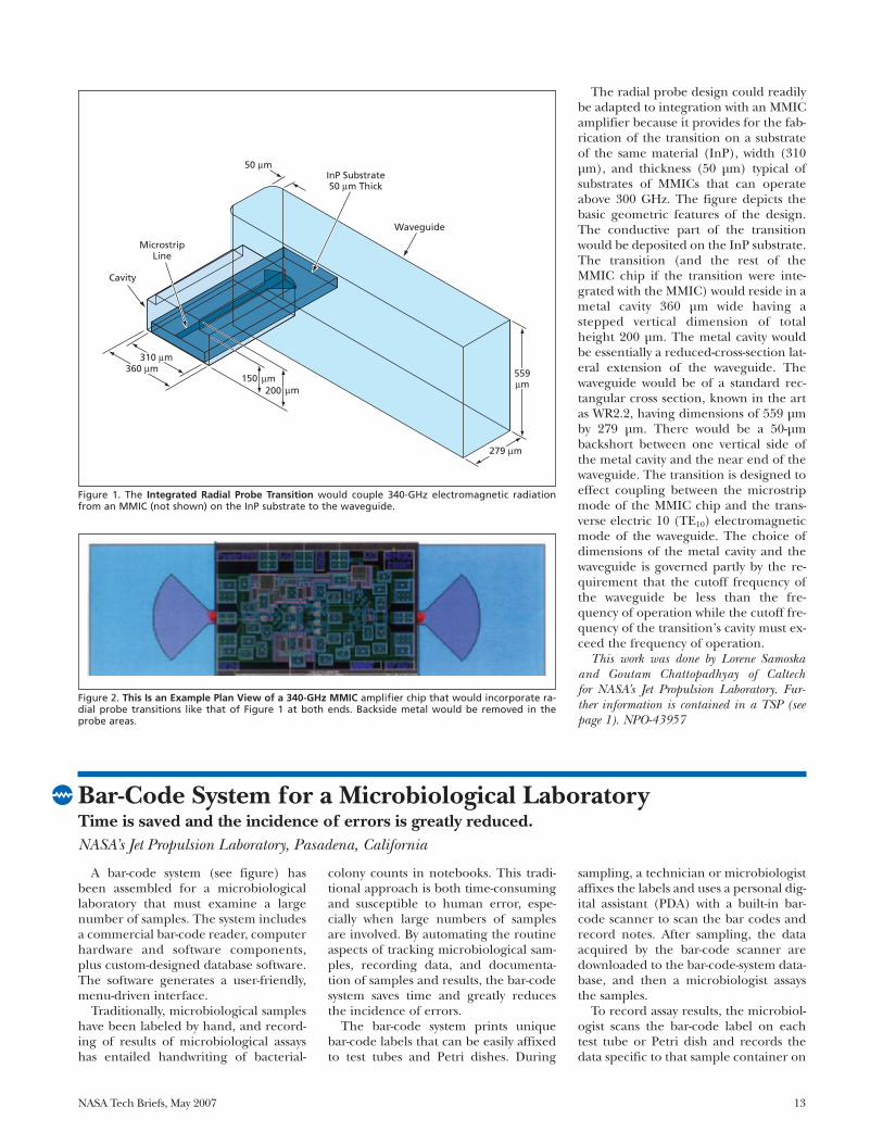
The radial probe design could readilybe adapted to integration with an MMICamplifier because it provides for the fab-rication of the transition on a substrateof the same material (InP), width (310µm), and thickness (50 µm) typical ofsubstrates of MMICs that can operateabove 300 GHz. The figure depicts thebasic geometric features of the design.The conductive part of the transitionwould be deposited on the InP substrate.The transition (and the rest of theMMIC chip if the transition were inte-grated with the MMIC) would reside in ametal cavity 360 µm wide having astepped vertical dimension of totalheight 200 µm. The metal cavity wouldbe essentially a reduced-cross-section lat-eral extension of the waveguide. Thewaveguide would be of a standard rec-tangular cross section, known in the artas WR2.2, having dimensions of 559 µmby 279 µm. There would be a 50-µmbackshort between one vertical side ofthe metal cavity and the near end of thewaveguide. The transition is designed toeffect coupling between the microstripmode of the MMIC chip and the trans-verse electric 10 (TE10) electromagneticmode of the waveguide. The choice ofdimensions of the metal cavity and thewaveguide is governed partly by the re-quirement that the cutoff frequency ofthe waveguide be less than the fre-quency of operation while the cutoff fre-quency of the transition’s cavity must ex-ceed the frequency of operation.
This work was done by Lorene Samoskaand Goutam Chattopadhyay of Caltech for NASA’s Jet Propulsion Laboratory. Fur-ther information is contained in a TSP (seepage 1). NPO-43957
NASA Tech Briefs, May 2007 13
A bar-code system (see figure) hasbeen assembled for a microbiologicallaboratory that must examine a largenumber of samples. The system includesa commercial bar-code reader, computerhardware and software components,plus custom-designed database software.The software generates a user-friendly,menu-driven interface.
Traditionally, microbiological sampleshave been labeled by hand, and record-ing of results of microbiological assayshas entailed handwriting of bacterial-
colony counts in notebooks. This tradi-tional approach is both time-consumingand susceptible to human error, espe-cially when large numbers of samplesare involved. By automating the routineaspects of tracking microbiological sam-ples, recording data, and documenta-tion of samples and results, the bar-codesystem saves time and greatly reducesthe incidence of errors.
The bar-code system prints uniquebar-code labels that can be easily affixedto test tubes and Petri dishes. During
sampling, a technician or microbiologistaffixes the labels and uses a personal dig-ital assistant (PDA) with a built-in bar-code scanner to scan the bar codes andrecord notes. After sampling, the dataacquired by the bar-code scanner aredownloaded to the bar-code-system data-base, and then a microbiologist assaysthe samples.
To record assay results, the microbiol-ogist scans the bar-code label on eachtest tube or Petri dish and records thedata specific to that sample container on
Bar-Code System for a Microbiological LaboratoryTime is saved and the incidence of errors is greatly reduced.NASA’s Jet Propulsion Laboratory, Pasadena, California
Figure 2. This Is an Example Plan View of a 340-GHz MMIC amplifier chip that would incorporate ra-dial probe transitions like that of Figure 1 at both ends. Backside metal would be removed in theprobe areas.
Cavity
MicrostripLine
Waveguide
Figure 1. The Integrated Radial Probe Transition would couple 340-GHz electromagnetic radiationfrom an MMIC (not shown) on the InP substrate to the waveguide.

14 NASA Tech Briefs, May 2007
an interactive computer display in a lo-cation reserved for those specific data.Inasmuch as the database software is de-signed to display only the record that
corresponds to agiven bar code, thepossibility of acci-dentally recordingdata in the wrongplace is eliminated(except, of course,for rare instancesof computer erroror errors in re-affix-ation of labels thathave fallen off). Inaddition, becausethe microbiologistno longer needs topainstakingly findthe correct place toenter data for eachassay plate, the bar-
code system accelerates the process ofreading plates and recording data.
The bar-code system greatly simplifiesthe documentation of the sampling
process. During sampling, the note-tak-ing capability of the PDA is comple-mented by the use of a digital camera:The sampling technician or microbiolo-gist takes a picture of each sample andrecords the picture number (as assignedby the digital camera) in the PDA. Oncethe data and pictures are downloaded tothe database, only a few mouse clicks arenecessary to generate a two-column re-port that displays the pictures in one col-umn and lists the corresponding sam-ples and pertinent information in theother column. In addition, the bar-codesystem automatically generates a reportof assay results. The data in the reportcan be exported to a spreadsheet foranalysis.
This work was done by Jennifer Law andLarry Kirschner of Caltech for NASA’s JetPropulsion Laboratory. Further informationis contained in a TSP (see page 1). NPO-30815
The Bar-Code System Hardware includes a personal computer, a desktopbar-code scanner (on the right by tubes and plates), and a PDA with a built-in bar-code scanner (left of the keyboard).
The first solid-state amplifier capableof producing gain at a frequency >215GHz has been demonstrated. This am-plifier is an intermediate product of acontinuing effort to develop amplifiershaving the frequency and gain charac-teristics needed for a forthcoming gen-eration of remote-sensing instrumentsfor detecting water vapor and possiblyother atmospheric constituents. Thereare also other potential uses for suchamplifiers in wide-band communica-tions, automotive radar, and millimeter-wave imaging for inspecting contents ofopaque containers.
This amplifier was fabricated as amonolithic microwave integrated-circuit(MMIC) chip containing InP high-elec-tron-mobility transistors (HEMTs) of0.07-µm gate length on a 50-µm-thickInP substrate. The passive componentson the chip are of the microstrip typeand were designed by use of advancedelectromagnetic-behavior-simulatin soft-ware. The amplifier contains threestages of HEMTs with matching net-works that comprise microstrip transmis-sion lines and metal/insulator/metal ca-pacitors. Bias is supplied viatransmission-line networks with bypasscapacitors on the gate and drain sides ofthe HEMTs.
The performance of the amplifier wasmeasured by use of the instrumentationsystem described in “Equipment for On-Wafer Testing From 220 to 325 GHz”
(NPO-40955), NASA Tech Briefs, Vol. 30,No. 1 (January 2006), page 38. This in-strumentation system, equivalent to atwo-port vector network analyzer, was
MMIC Amplifier Produces Gain of 10 dB at 235 GHzThis is the fastest MMIC amplifier reported to date.NASA’s Jet Propulsion Laboratory, Pasadena, California
The MMIC Amplifier described in the text is shown mounted for testing with custom wafer probes fortesting at 220 to 325 GHz.
NASA Tech Briefs, May 2007 15
equipped with custom wafer probes (seefigure) designed for the noted fre-quency band, which is that of WR-3waveguides [waveguides having a stan-dard rectangular cross section of 0.0340by 0.0170 in. (0.8636 by 0.4318 mm)].
Among other things, the measurementsshowed a peak gain of 10 dB at a fre-quency of 235 GHz.
This work was done by Douglas Dawson,King Man Fung, Karen Lee, LoreneSamoska, Mary Wells, Todd Gaier, and
Pekka Kangaslahti of Caltech; and RonaldGrundbacher, Richard Lai, Rohit Raja,and Po-Hsin Liu of NGST for NASA’s JetPropulsion Laboratory. Further informa-tion is contained in a TSP (see page 1).NPO-42202
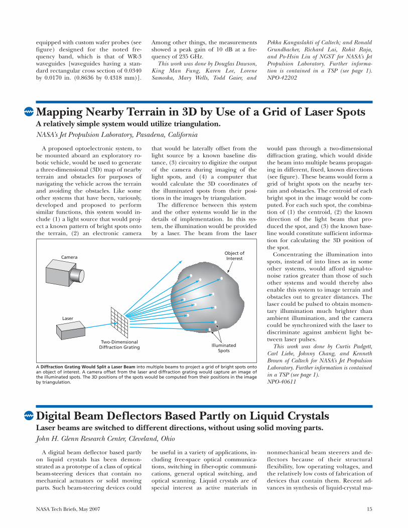
A proposed optoelectronic system, tobe mounted aboard an exploratory ro-botic vehicle, would be used to generatea three-dimensional (3D) map of nearbyterrain and obstacles for purposes ofnavigating the vehicle across the terrainand avoiding the obstacles. Like someother systems that have been, variously,developed and proposed to performsimilar functions, this system would in-clude (1) a light source that would proj-ect a known pattern of bright spots ontothe terrain, (2) an electronic camera
that would be laterally offset from thelight source by a known baseline dis-tance, (3) circuitry to digitize the outputof the camera during imaging of thelight spots, and (4) a computer thatwould calculate the 3D coordinates ofthe illuminated spots from their posi-tions in the images by triangulation.
The difference between this systemand the other systems would lie in thedetails of implementation. In this sys-tem, the illumination would be providedby a laser. The beam from the laser
would pass through a two-dimensionaldiffraction grating, which would dividethe beam into multiple beams propagat-ing in different, fixed, known directions(see figure). These beams would form agrid of bright spots on the nearby ter-rain and obstacles. The centroid of eachbright spot in the image would be com-puted. For each such spot, the combina-tion of (1) the centroid, (2) the knowndirection of the light beam that pro-duced the spot, and (3) the known base-line would constitute sufficient informa-tion for calculating the 3D position ofthe spot.
Concentrating the illumination intospots, instead of into lines as in someother systems, would afford signal-to-noise ratios greater than those of suchother systems and would thereby alsoenable this system to image terrain andobstacles out to greater distances. Thelaser could be pulsed to obtain momen-tary illumination much brighter thanambient illumination, and the cameracould be synchronized with the laser todiscriminate against ambient light be-tween laser pulses.
This work was done by Curtis Padgett,Carl Liebe, Johnny Chang, and KennethBrown of Caltech for NASA’s Jet PropulsionLaboratory. Further information is containedin a TSP (see page 1).NPO-40611
Mapping Nearby Terrain in 3D by Use of a Grid of Laser SpotsA relatively simple system would utilize triangulation.NASA’s Jet Propulsion Laboratory, Pasadena, California
Camera
Laser
Two-DimensionalDiffraction Grating
Object ofInterest
IlluminatedSpots
A Diffraction Grating Would Split a Laser Beam into multiple beams to project a grid of bright spots ontoan object of interest. A camera offset from the laser and diffraction grating would capture an image ofthe illuminated spots. The 3D positions of the spots would be computed from their positions in the imageby triangulation.
A digital beam deflector based partlyon liquid crystals has been demon-strated as a prototype of a class of opticalbeam-steering devices that contain nomechanical actuators or solid movingparts. Such beam-steering devices could
be useful in a variety of applications, in-cluding free-space optical communica-tions, switching in fiber-optic communi-cations, general optical switching, andoptical scanning. Liquid crystals are ofspecial interest as active materials in
nonmechanical beam steerers and de-flectors because of their structuralflexibility, low operating voltages, andthe relatively low costs of fabrication ofdevices that contain them. Recent ad-vances in synthesis of liquid-crystal ma-
Digital Beam Deflectors Based Partly on Liquid CrystalsLaser beams are switched to different directions, without using solid moving parts.John H. Glenn Research Center, Cleveland, Ohio
16 NASA Tech Briefs, May 2007
terials and design of the nematic-liq-uid-crystal cells have resulted in signif-icant improvements in properties(e.g., short response times and bire-fringence) that are important for ef-fective beam steering.
A beam deflector of this type is a mul-tistage device. Each stage consists mainlyof (1) a passive birefringent prism madeof yttrium orthovanadate (YVO4) [alter-natively, it could be made of a uniaxialsmectic A liquid crystal] and (2) aswitchable polarization rotator in theform of a cell containing a twisted ne-matic liquid crystal. A linearly polarizedlaser beam that one seeks to deflect trav-els through the liquid-crystal cell on theway to the passive birefringent prism. Ifno voltage is applied across the cell(“off” state), passage though the cellchanges the direction of polarization by
90°. If a suitable non-zero voltage is ap-plied across the cell (“on” state), thenthe polarization direction remains un-changed after passage through the cell.Therefore, by virtue of birefringence,depending on which of the two selec-table polarizations has been imparted tothe beam by the liquid-crystal cell, thebeam propagates through the crystal ineither of two different directions.
If a beam deflector of this type con-tained N stages, then it would be possi-ble to switch the input laser beam toany of 2N different output directionsthrough electrical switching of the liq-uid-crystal cells. The prototype deviceoperates with an incident 633-nm-wave-length beam from a helium/neon laser.It contains 4 stages and, hence, can de-flect the beam to any of 24 = 16 outputdirections. In this case, the directions
are separated by increments of 8 milli-radians. To obtain a relatively short re-sponse time (0.5 ms), the cells aremade from so-called dual-frequency ne-matic liquid crystals and operated in aspecial addressing scheme that featuresamplitude- and frequency-modulateddriving voltage.
This work was done by John J. Pouch andFelix A. Miranda of Glenn Research Center;Liubov Kreminska, Oleg Pishnyak, AndriiGolovin, and Oleg D. Lavrentovich of KentState University; and Bruce K. Winker ofRockwell Scientific Company LLC. Further in-formation is contained in a TSP (see page 1).
Inquiries concerning rights for the commer-cial use of this invention should be addressedto NASA Glenn Research Center, InnovativePartnerships Office, Attn: Steve Fedor, MailStop 4–8, 21000 Brookpark Road, Cleve-land, Ohio 44135. Refer to LEW-17947-1.
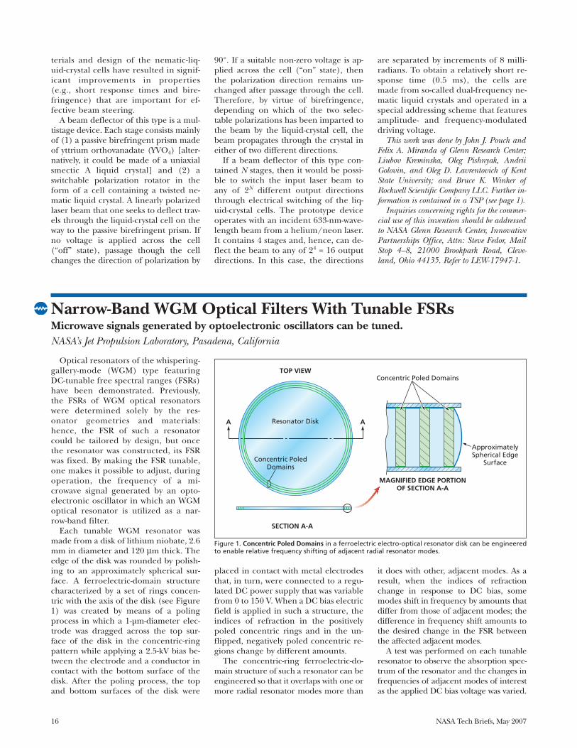
Optical resonators of the whispering-gallery-mode (WGM) type featuringDC-tunable free spectral ranges (FSRs)have been demonstrated. Previously,the FSRs of WGM optical resonatorswere determined solely by the res-onator geometries and materials:hence, the FSR of such a resonatorcould be tailored by design, but oncethe resonator was constructed, its FSRwas fixed. By making the FSR tunable,one makes it possible to adjust, duringoperation, the frequency of a mi-crowave signal generated by an opto-electronic oscillator in which an WGMoptical resonator is utilized as a nar-row-band filter.
Each tunable WGM resonator wasmade from a disk of lithium niobate, 2.6mm in diameter and 120 μm thick. Theedge of the disk was rounded by polish-ing to an approximately spherical sur-face. A ferroelectric-domain structurecharacterized by a set of rings concen-tric with the axis of the disk (see Figure1) was created by means of a polingprocess in which a 1-µm-diameter elec-trode was dragged across the top sur-face of the disk in the concentric-ringpattern while applying a 2.5-kV bias be-tween the electrode and a conductor incontact with the bottom surface of thedisk. After the poling process, the topand bottom surfaces of the disk were
placed in contact with metal electrodesthat, in turn, were connected to a regu-lated DC power supply that was variablefrom 0 to 150 V. When a DC bias electricfield is applied in such a structure, theindices of refraction in the positivelypoled concentric rings and in the un-flipped, negatively poled concentric re-gions change by different amounts.
The concentric-ring ferroelectric-do-main structure of such a resonator can beengineered so that it overlaps with one ormore radial resonator modes more than
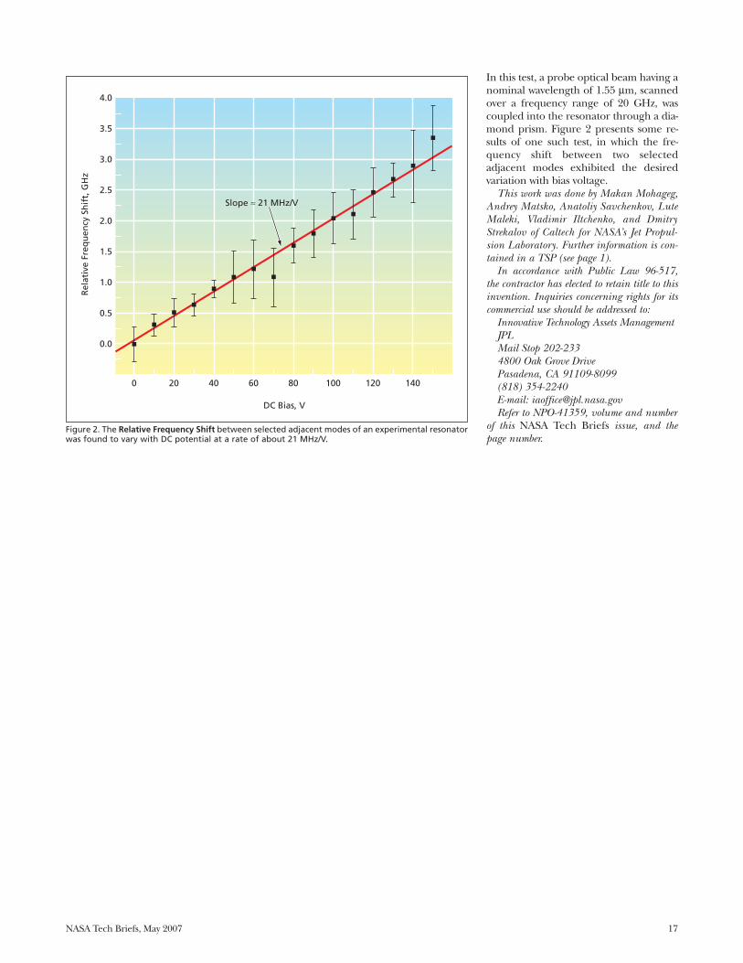
it does with other, adjacent modes. As aresult, when the indices of refractionchange in response to DC bias, somemodes shift in frequency by amounts thatdiffer from those of adjacent modes; thedifference in frequency shift amounts tothe desired change in the FSR betweenthe affected adjacent modes.
A test was performed on each tunableresonator to observe the absorption spec-trum of the resonator and the changes infrequencies of adjacent modes of interestas the applied DC bias voltage was varied.
Narrow-Band WGM Optical Filters With Tunable FSRsMicrowave signals generated by optoelectronic oscillators can be tuned.NASA’s Jet Propulsion Laboratory, Pasadena, California
Concentric Poled Domains
MAGNIFIED EDGE PORTIONOF SECTION A-A
ApproximatelySpherical Edge
SurfaceConcentric PoledDomains
Resonator DiskA
TOP VIEW
SECTION A-A
A
Figure 1. Concentric Poled Domains in a ferroelectric electro-optical resonator disk can be engineeredto enable relative frequency shifting of adjacent radial resonator modes.
NASA Tech Briefs, May 2007 17
In this test, a probe optical beam having anominal wavelength of 1.55 μm, scannedover a frequency range of 20 GHz, wascoupled into the resonator through a dia-mond prism. Figure 2 presents some re-sults of one such test, in which the fre-quency shift between two selectedadjacent modes exhibited the desiredvariation with bias voltage.
This work was done by Makan Mohageg,Andrey Matsko, Anatoliy Savchenkov, LuteMaleki, Vladimir Iltchenko, and DmitryStrekalov of Caltech for NASA’s Jet Propul-sion Laboratory. Further information is con-tained in a TSP (see page 1).
In accordance with Public Law 96-517,the contractor has elected to retain title to thisinvention. Inquiries concerning rights for itscommercial use should be addressed to:
Innovative Technology Assets ManagementJPLMail Stop 202-2334800 Oak Grove DrivePasadena, CA 91109-8099(818) 354-2240E-mail: [email protected] to NPO-41359, volume and number
of this NASA Tech Briefs issue, and thepage number.
0
0.0
0.5
1.0
1.5
2.0
2.5
3.0
3.5
4.0
20 40 60
DC Bias, V
Slope ≈ 21 MHz/V
Rel
ativ
e Fr
equ
ency
Sh
ift,
GH
z
80 100 120 140
Figure 2. The Relative Frequency Shift between selected adjacent modes of an experimental resonatorwas found to vary with DC potential at a rate of about 21 MHz/V.

NASA Tech Briefs, May 2007 19
Software
Better Finite-Element Analy-sis of Composite ShellStructures
A computer program implements a fi-nite-element-based method of predict-ing the deformations of thin aerospacestructures made of isotropic materials oranisotropic fiber-reinforced compositematerials. The technique and corre-sponding software are applicable to thinshell structures in general and are par-ticularly useful for analysis of thin beam-like members having open cross-sections(e.g. I-beams and C-channels) in whichsignificant warping can occur.
In many popular commercial pack-ages that offer the two-dimensional fi-nite elements option, inaccuracies arisefrom node offsets and overlapping of el-ements; in other formulations utilizingone-dimensional discretization, anglesof twist tend to be overestimated. In thepresent formulation, a shell elementthat incorporates “floating” referencesurfaces on which nodal points reside isdeveloped. This element concept facili-tates the formation of proper connec-tions among elements and thereby elim-inates the inaccuracies attributable toelement-overlapping and nodal offsetsin the other methods.
This program was written by GregoryClarke of Goddard Space Flight Center. Fur-ther information is contained in a TSP (seepage 1).GSC-14756-1
Computing Spacecraft-Pointing Vectors for LimbTracking
LMBTRK is a computer program thatis used together with two software li-braries known as ERHAND and HY-BRRD to generate spacecraft-pointingvectors for limb-tracking maneuversneeded for experiments on propagationof radio signals through planetary at-mospheres. LMBTRK determines, as afunction of time, the direction in whichone must point a ray (representing aradio beam) emitted by a spacecraft inorder to make the ray pass through a
planetary atmosphere on its way to a re-ceiving station at a known location.LMBTRK was written for Sun computersrunning the Solaris operating systemand has been running on a cluster ofsuch computers used in the Radio Sci-ence System of the Cassini Spacecraftmission.
This program was written by Nicole Rap-paport and Essam Marouf of Caltech forNASA’s Jet Propulsion Laboratory. Furtherinformation is contained in a TSP (see page1).
This software is available for commerciallicensing. Please contact Karina Edmonds ofthe California Institute of Technology at(626) 395-2322. Refer to NPO-40542.
Enhanced Master ControllerUnit Tester
The Enhanced Master ControllerUnit Tester (EMUT) software is a toolfor development and testing of softwarefor a master controller (MC) flight com-puter. The primary function of theEMUT software is to simulate interfacesbetween the MC computer and externalanalog and digital circuitry (includingother computers) in a rack of equip-ment to be used in scientific experi-ments. The simulations span the rangeof nominal, off-nominal, and erroneousoperational conditions, enabling thetesting of MC software before all theequipment becomes available.
The EMUT software comprises aWin32-based set of three programs thatrun on different computers and arelinked by Common Object Request Bro-ker (CORBA) Ethernet communica-tions. The main program, denoted theEMUT 1553 Application, generates agraphical user interface and is responsi-ble for all communications via severalMIL-STD-1553B data buses and for log-ging of output data. The second pro-gram, denoted the Analog Application,implements mathematical models ofequipment (e.g., sensors and valves) andanalog signals generated by the equip-ment and is responsible for all analog-signal communications with the MC.The third program, denoted the EMUT
Model Viewer, provides a graphical in-terface for viewing the statuses of theaforementioned models.
This program was written by Patricia Ben-son, Yvette Johnson, and Brian Johnson ofMarshall Space Flight Center; PhilipWilliams of Dynamic Concepts, Inc.; GeoffreyBurton of Madison Research Corp.; and An-thony McCoy of ERC. Further information iscontained in a TSP (see page 1).MFS-32172-1
Rover Graphical Simulator Rover Graphical Simulator (RGS) is a
package of software that generates im-ages of the motion of a wheeled roboticexploratory vehicle (rover) across ter-rain that includes obstacles and regionsof varying traversability. The simulatedrover moves autonomously, utilizing rea-soning and decision-making capabilitiesof a fuzzy-logic navigation strategy tochoose its path from an initial to a finalstate. RGS provides a graphical user in-terface for control and monitoring ofsimulations.
The numerically simulated motion isrepresented as discrete steps with a con-stant time interval between updates. Ateach simulation step, a dot is placed atthe old rover position and a graphicalsymbol representing the rover is re-drawn at the new, updated position. Theeffect is to leave a trail of dots depictingthe path traversed by the rover, the dis-tances between dots being proportionalto the local speed. Obstacles and regionsof low traversability are depicted as filledcircles, with buffer zones around themindicated by enclosing circles. The simu-lated robot is equipped with onboardsensors that can detect regional terraintraversability and local obstacles out tospecified ranges. RGS won the NASAGroup Achievement Award in 2002.
This program was written by Bruce Bonand Homayoun Seraji of Caltech for NASA’sJet Propulsion Laboratory. Further informa-tion is contained in a TSP (see page 1).
This software is available for commerciallicensing. Please contact Karina Edmonds ofthe California Institute of Technology at(626) 395-2322. Refer to NPO-35223.

NASA Tech Briefs, May 2007 21
Thermally sprayed dielectric ceramiccoatings are the primary means of at-taching strain and temperature gaugesto hot-section rotating parts of turbineengines. As hot-section temperatures in-crease, lifetimes of installed gauges de-crease, and seldom exceed one hourabove 2,000 °F (≈1,100 °C). Advancedengine components are expected to op-erate at temperatures approaching2,200 °F (≈1,200 °C), and the requiredhigh-temperature lifetime is 10 hoursminimum.
Typically, to enable a ceramic coatingto adhere to the smooth surface of anengine component, a thermally sprayedNiCrAlY or NiCoCrAlY bond coat is ap-plied to the smooth surface, therebyproviding a textured surface to which
the ceramic coat can adhere. The mainfailure mechanism of this system is deco-hesion and/or delamination at the in-terface between the ceramic top coatand the bond coat, caused by oxidationof the bond coat and stresses from themismatch between the coefficients ofthermal expansion of the ceramic topcoat and the metallic bond coat.
The approach taken to increase thehigh-temperature lifetime of a gauge at-tached to an engine component by themethod described above involves (1) se-lective oxidation of the bond coat bymeans of a heat treatment in reducedoxygen partial pressure followed by (2)the application of a noble-metal diffu-sion barrier. In experiments to test thisapproach, heat treatments of NiCoCrAlY
bond coats were carried out in a tubefurnace in which, in each case, the tem-perature was alternately (1) increased ata rate of 3 °C per minute and (2) heldsteady for one hour until the desiredtemperature was reached. The tube fur-nace was continuously purged with drynitrogen gas. A final heat-treatment tem-perature range of 1,600 to 1,800 °F (871to 982 °C) proved most beneficial.
Test coupons were made to enableevaluation of the cycle lives of variousbond coats, including some made fromthe commercially available coating mate-rials Praxair 171 (an NiCoCrAlY formu-lation) and Praxair 343 (an NiCrAlY for-mulation). Each test coupon included abase-metal coupon of Inconel™ 718nickel alloy. One of the bond-coatingmaterials to be tested was thermallysprayed on the metal, the coupon wassubjected to the aforementioned heattreatment at reduced oxygen partialpressure, then a ceramic dielectric top-coat was thermally sprayed onto thebond coat. To provide a basis of compar-ison for evaluation of the relative meritsof the various surface treatments andheat treatments, some of the NiCoCrAlYand NiCrAlY bond coats were incorpo-rated into the coupons in the as-sprayedcondition: that is, the affected couponswere not subjected to the heat treatmentat reduced oxygen partial pressure.
Each coupon was mounted on an In-conel™ 718 nickel-alloy fixture and
Increasing Durability of Flame-Sprayed Strain Gauges Low-oxygen heat treatments and internal platinum oxygen-diffusion barriers extend lifetimes. John H. Glenn Research Center, Cleveland, Ohio
ThermallySprayedCeramicOvercoat
Test Coupon With Thermally
Sprayed Bond Coat
Test Fixture
Ceramic Heat Shield
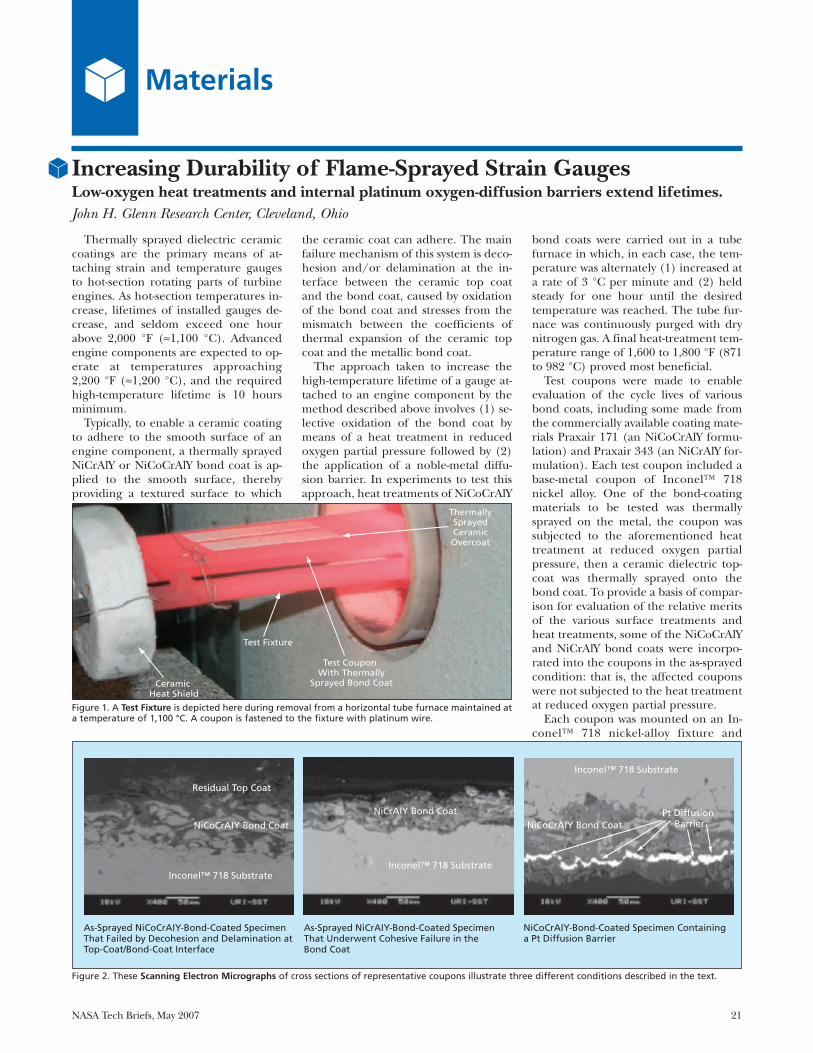
Figure 1. A Test Fixture is depicted here during removal from a horizontal tube furnace maintained ata temperature of 1,100 °C. A coupon is fastened to the fixture with platinum wire.
Residual Top Coat
NiCoCrAIY Bond Coat
Inconel™ 718 Substrate
NiCrAIY Bond Coat
Inconel™ 718 Substrate
Inconel™ 718 Substrate
NiCoCrAIY Bond Coat Pt Diffusion
Barrier
As-Sprayed NiCoCrAIY-Bond-Coated Specimen That Failed by Decohesion and Delamination at Top-Coat/Bond-Coat Interface
As-Sprayed NiCrAIY-Bond-Coated Specimen That Underwent Cohesive Failure in the Bond Coat
NiCoCrAIY-Bond-Coated Specimen Containing a Pt Diffusion Barrier
Materials
Figure 2. These Scanning Electron Micrographs of cross sections of representative coupons illustrate three different conditions described in the text.
22 NASA Tech Briefs, May 2007
placed in the tube furnace, wherein itwas heated to 1,150 °C and held at thistemperature for one hour. The test fix-ture was then retracted from the furnace(see Figure 1) and allowed to cool to 150°C. The cooling process took approxi-mately 5 to 6 minutes. Upon reaching150 °C, the test fixture with the couponwas placed back in the furnace and re-heated to 1,150 °C. The entire heating-and-cooling sequence was consideredone cycle, and the lifetimes of thecoupons were assessed on the basis ofthe numbers of cycles to failure.
The heat treatment of the NiCoCrAlYbond coats at reduced oxygen partialpressure yielded a significant increase inlifetimes: Coupons heat-treated to 1,750°F (954 °C) at reduced oxygen partialpressure exhibited more than doublethe cycle lives of those containing as-sprayed NiCoCrAlY. This considerableincrease in life can be attributed to thefact that selective oxidation of the alu-minum and chromium in the bond coatyielded a graded interface. The heattreatment of the NiCrAlY bond coatsyielded little or no increase in lifetimes.
The failure mechanisms of thecoupons containing NiCoCrAlY bondcoats differed from those of the coupons
containing the NiCrAlY bond coats: TheNiCoCrAlY-bond-coated specimensfailed by decohesion and/or delamina-tion at the interfaces between the topand bond coats. The NiCrAlY-bond-coated specimens underwent cohesivefailure within the bond coats. Evidenceof failure by these mechanisms can beseen in the left and the middle part, re-spectively, of Figure 2.
In an effort to reduce the extent of in-ternal oxidation in the bond coats, plat-inum and rhodium coats were employedas diffusion barriers. Initially, as-sprayedNiCoCrAlY-bond-coated coupons werecoated with platinum to a thickness of 2µm by physical vapor deposition (PVD).An example of a platinum diffusion bar-rier can be seen in the right part of Fig-ure 2. The platinum-coated Inconelcoupons were heat-treated to 1,800 °F(982 °C), then magnesium aluminatespinel top coats were thermally sprayedover the platinum coats. Rhodium diffu-sion barriers were applied to the sur-faces of NiCoCrAlY-bond-coatedcoupons by pen electroplating. (Penelectroplating was investigated as ameans of forming diffusion barriers be-cause it is easy to perform and does notentail costly capital investment.)
The rhodium diffusion barriersyielded only a marginal increase in thelives of NiCoCrAlY-bond-coatedcoupons. However, platinum diffusionbarriers applied by PVD in conjunctionwith reduced-oxygen-partial-pressureheat treatment yielded substantial in-creases in lifetimes. The platinum filmswere thick enough to constitute oxygen-diffusions barriers that slowed thegrowth of internal oxides by promotingthe formation of alumina-rich scale atthe interfaces between the top and bondcoats. The best results achieved to datewere realized by use of sputtered plat-inum diffusion barriers in conjunctionwith heat treatments to 1,800 °F (982°C) at reduced oxygen partial pressures.This combination yielded a four-fold in-crease in the fatigue lives of NiCoCrAlY-bond-coated coupons.
This work was done by Otto J. Gregory andMarkus A. Downey of the University of RhodeIsland, and Steve Wnuk and Vince Wnuk ofHPI Inc. for Glenn Research Center.
Inquiries concerning rights for the commer-cial use of this invention should be addressedto NASA Glenn Research Center, InnovativePartnerships Office, Attn: Steve Fedor, MailStop 4–8, 21000 Brookpark Road, Cleve-land, Ohio 44135. Refer to LEW-17530-1.
In experiments conducted as part of acontinuing effort to incorporate multi-functionality into advanced compositematerials, blends of multi-walled carbonnanotubes and a resin denoted “PETI-330” (wherein “PETI” is an abbreviationfor “phenylethynyl-terminated imide”)were prepared, characterized, and fabri-cated into moldings. PETI-330 was se-lected as the matrix resin in these exper-iments because of its low melt viscosity(<10 poise at a temperature of 280 °C),excellent melt stability (lifetime >2hours at 280 °C), and high temperatureperformance (>1,000 hours at 288 °C).The multi-walled carbon nanotubes(MWCNTs), obtained from the Univer-sity of Kentucky, were selected becauseof their electrical and thermal conduc-tivity and their small diameters. The pur-pose of these experiments was to deter-mine the combination of thermal,electrical, and mechanical propertiesachievable while still maintaining melt
processability.The PETI-330/MWCNT mixtures
were prepared at concentrations rang-ing from 3 to 25 weight-percent of MW-CNTs by dry mixing of the constituentsin a ball mill using zirconia beads. Theresulting powders were characterized fordegree of mixing and thermal and rheo-logical properties. The neat resin wasfound to have melt viscosity between 5and 10 poise. At 280 °C and a fixedstrain rate, the viscosity was found to in-crease with time. At this temperature,the phenylethynyl groups do not readilyreact and so no significant curing of theresin occurred. For MWCNT-filled sam-ples, melt viscosity was reasonably steadyat 280 °C and was greater in samplescontaining greater proportions of MWC-NTs. The melt viscosity for 20 weight-percent of MWCNTs was found to be≈28,000 poise, which is lower than theinitial estimated allowable maximumvalue of 60,000 poise for injection mold-
ing. Hence, MWCNT loadings of asmuch as 20 percent were deemed to besuitable compositions for scale-up.
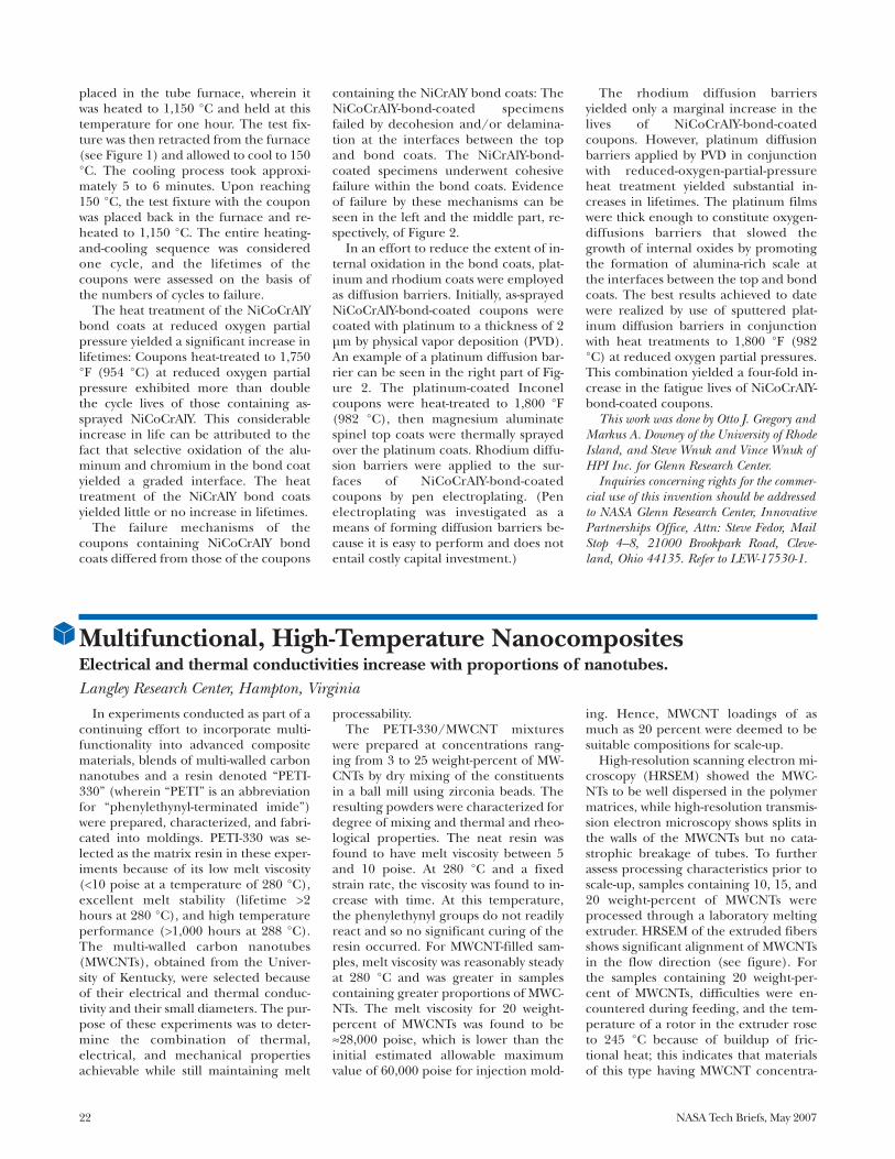
High-resolution scanning electron mi-croscopy (HRSEM) showed the MWC-NTs to be well dispersed in the polymermatrices, while high-resolution transmis-sion electron microscopy shows splits inthe walls of the MWCNTs but no cata-strophic breakage of tubes. To furtherassess processing characteristics prior toscale-up, samples containing 10, 15, and20 weight-percent of MWCNTs wereprocessed through a laboratory meltingextruder. HRSEM of the extruded fibersshows significant alignment of MWCNTsin the flow direction (see figure). Forthe samples containing 20 weight-per-cent of MWCNTs, difficulties were en-countered during feeding, and the tem-perature of a rotor in the extruder roseto 245 °C because of buildup of fric-tional heat; this indicates that materialsof this type having MWCNT concentra-
Multifunctional, High-Temperature Nanocomposites Electrical and thermal conductivities increase with proportions of nanotubes. Langley Research Center, Hampton, Virginia

NASA Tech Briefs, May 2007 23
tions ≥20 weight- percent may not bemelt-processable.
On the basis of the results from theforegoing characterizations, samplescontaining 10, 15, and 20 weight-per-cent of MWCNTs were scaled up tomasses of ≈300 g and used to make spec-imens having dimensions of 10.2 by 15.2by 0.32 cm. These specimens weremolded by (1) injecting the mixtures, attemperatures between 260 and 280 °C,into a tool made of the low-thermal-ex-pansion alloy Invar® and then (2) curingfor 1 hour at 371°C. The tool was de-signed to impart shear during the injec-
tion process in an attempt to achievesome alignment of the MWCNTs in theflow direction.
Qualitatively, the moldings from the 10and 15 weight-percent samples appearedto be good. The moldings were subse-quently characterized with respect tothermal, mechanical, and electrical prop-erties. However, as expected from the re-sults of the extrusion experiments, the 20weight-percent sample could not be in-jected because of its higher viscosity.
The hardness value of each moldedPETI-330/MWCNT specimen was foundto be lower than that of the neat resin in
the sense that an in-denter was found topenetrate to agreater depth or anenhanced plastic de-formation of the ma-terial was observed.The neat resin speci-men was found to beelectrically insulat-ing. For the otherspecimens, the elec-trical resistivity wasfound to decreasewith increasing con-centration of MWC-NTs, ranging from8.86 × 103 Ω/cm forthe 10 weight-per-cent sample to 5.13 ×
103 Ω/cm for the 15 weight-percent sam-ple. The thermal conductivities werefound to increase with the proportion ofMWCNTs, ranging from 0.219 W/(m·K)for the neat resin specimen to 0.577W/(m·K) for the 10 weight-percentspecimen and 0.777 W/(m·K) for the 15weight-percent specimen. This trend inthermal conductivity suggests that nan-otubes form networks in the polymermatrices that conduct heat, but not tothe extent expected based on the highthermal conductivity of the MWCNTs.
Upon machining of the specimens toprepare them for mechanical tests,voids were observed. Unfortunately,these voids made the samples unsuit-able for determination of mechanicalproperties. Notwithstanding the presentlack of data on mechanical properties,the electrical and thermal propertiesand processing characteristics of thesematerials offer significant potential forapplications in which multifunctionalitymay be required.
This work was done by John W. Connell,Joseph G. Smith, Emilie J. Siochi, and DennisC. Working of Langley Research Center; JimM. Criss of M&P Technologies; Kent A. Wat-son and Donavon M. Delozier of the Na-tional Institute of Aerospace; and SayataGhose of the National Research Council. Fur-ther information is contained in a TSP (seepage 1).LAR-17082-1
MWCNTs Were Substantially Aligned along the flow direction after ex-trusion, as shown in this high-resolution scanning electron micrograph.
The term “secondary polymer layeredimpregnated tile” (“SPLIT”) denotes atype of ablative composite-material ther-mal-insulation tiles having engineered,spatially non-uniform compositions. Theterm “secondary” refers to the fact thateach tile contains at least two polymerlayers wherein endothermic reactionsabsorb considerable amounts of heat,thereby helping to prevent overheatingof an underlying structure. These tileswere invented to afford lighter-weight al-ternatives to the reusable thermal-insula-tion materials heretofore variously usedor considered for use in protecting thespace shuttles and other spacecraft fromintense atmospheric-entry heating. Tilesof this type could also be useful on Earthas relatively lightweight components offire-retardant structures.
The SPLIT concept admits to so manydifferent combinations of constituentmaterials, spatial distributions of the ma-terials, and fabrication processes, that itis not possible to even list, much lesssummarize or describe all of them. In-stead, a representative example mustserve to illustrate the main principles.The starting material for fabricating atypical SPLIT is a porous substrate, hav-ing a void volume fraction of about 90percent, that comprises a rigid tile orfabric made from any of a large varietyof carbon fibers and/or ceramics fibers.The fiber composition can be the samethroughout the thickness or can begraded: for example, it can differ amongfront, middle, and rear layers.
The front layer, which is the one tobe exposed directly to intense heating,
is typically impregnated with a ther-mosetting resin (e.g., a phenolic or asilicone). This layer becomes the firstline of defense against intense heating:a large amount of heat is absorbed inthe pyrolysis of the front polymer layerand is dissipated to the environmentthrough a combination of outflow ofthe pyrolysis gas, and thermal radiationfrom the char layer formed in the py-rolysis. The outflow of the pyrolysis gasalso provides further protectionagainst heating by blocking the inflowof hot ambient gas.
The middle layer (if any) is typicallynot impregnated. The back layer is theone to be placed in contact or proximityto the structure to be protected. Theback layer is initially impregnated with athermoplastic polymer (the secondary
Multilayer Impregnated Fibrous Thermal Insulation Tiles Temperature rises are limited by transpiration cooling. Ames Research Center, Moffett Field, California
24 NASA Tech Briefs, May 2007
polymer) in solution and the solvent isallowed to evaporate, so that the fibersin the back layer become coated with thethermoplastic but the layer retains sub-stantial porosity. The secondary polymeris chosen to be one that pyrolizes com-pletely or nearly completely to gaseousproducts (i.e., leaving little or no solidresidue), at a temperature much lowerthan the pyrolysis temperature of thefront layer. For example, polystyreneand poly (methyl methacrylate) decom-pose at temperatures between 350 and450 °C.
Eventually, some heat penetrates thefront layer and diffuses to the back layer,where the lower-temperature pyrolysisreaction of the secondary polymer re-tards the transfer of heat to the structureto be protected. The pyrolysis gas fromthe secondary polymer escapes throughthe middle (if any) and front layers,thereby effectively preventing excessiveheating of the underlying structure
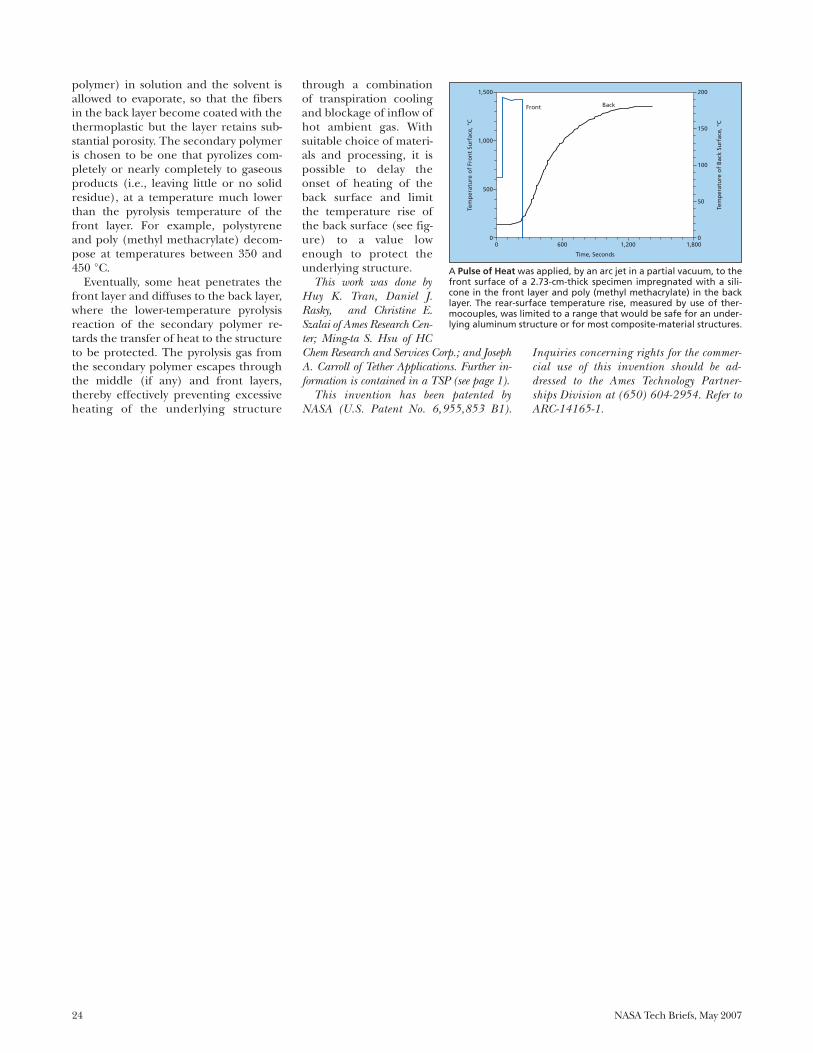
through a combinationof transpiration coolingand blockage of inflow ofhot ambient gas. Withsuitable choice of materi-als and processing, it ispossible to delay theonset of heating of theback surface and limitthe temperature rise ofthe back surface (see fig-ure) to a value lowenough to protect theunderlying structure.
This work was done byHuy K. Tran, Daniel J.Rasky, and Christine E.Szalai of Ames Research Cen-ter; Ming-ta S. Hsu of HCChem Research and Services Corp.; and JosephA. Carroll of Tether Applications. Further in-formation is contained in a TSP (see page 1).
This invention has been patented byNASA (U.S. Patent No. 6,955,853 B1).
Inquiries concerning rights for the commer-cial use of this invention should be ad-dressed to the Ames Technology Partner-ships Division at (650) 604-2954. Refer toARC-14165-1.
1,500
1,000
500
0 0
50
100
150
200
0 600 1,200 1,800
Front Back
Time, Seconds
Tem
per
atu
re o
f Fr
on
t Su
rfac
e, °
C
Tem
per
atu
re o
f B
ack
Surf
ace,
°C
A Pulse of Heat was applied, by an arc jet in a partial vacuum, to thefront surface of a 2.73-cm-thick specimen impregnated with a sili-cone in the front layer and poly (methyl methacrylate) in the backlayer. The rear-surface temperature rise, measured by use of ther-mocouples, was limited to a range that would be safe for an under-lying aluminum structure or for most composite-material structures.
NASA Tech Briefs, May 2007 25
Manufacturing & Prototyping
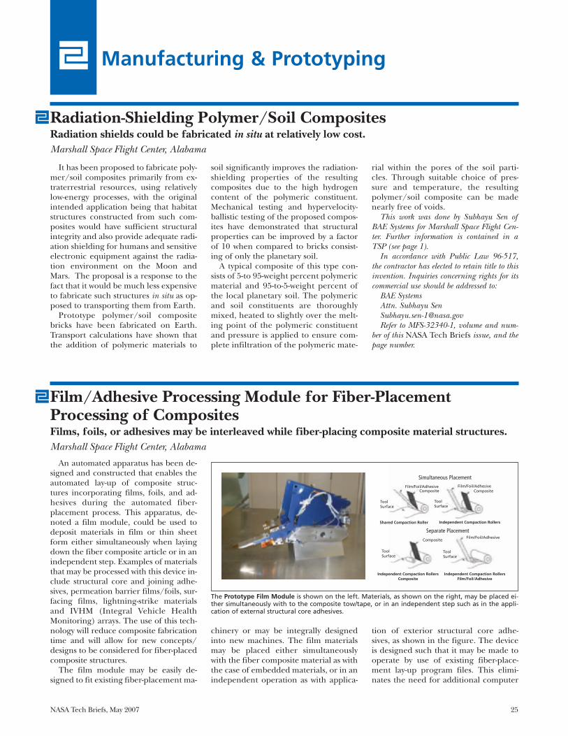
An automated apparatus has been de-signed and constructed that enables theautomated lay-up of composite struc-tures incorporating films, foils, and ad-hesives during the automated fiber-placement process. This apparatus, de-noted a film module, could be used todeposit materials in film or thin sheetform either simultaneously when layingdown the fiber composite article or in anindependent step. Examples of materialsthat may be processed with this device in-clude structural core and joining adhe-sives, permeation barrier films/foils, sur-facing films, lightning-strike materialsand IVHM (Integral Vehicle HealthMonitoring) arrays. The use of this tech-nology will reduce composite fabricationtime and will allow for new concepts/designs to be considered for fiber-placedcomposite structures.
The film module may be easily de-signed to fit existing fiber-placement ma-
chinery or may be integrally designedinto new machines. The film materialsmay be placed either simultaneouslywith the fiber composite material as withthe case of embedded materials, or in anindependent operation as with applica-
tion of exterior structural core adhe-sives, as shown in the figure. The deviceis designed such that it may be made tooperate by use of existing fiber-place-ment lay-up program files. This elimi-nates the need for additional computer
Film/Adhesive Processing Module for Fiber-PlacementProcessing of CompositesFilms, foils, or adhesives may be interleaved while fiber-placing composite material structures.Marshall Space Flight Center, Alabama
Film/Foil/AdhesiveComposite
ToolSurface
ToolSurface
Film/Foil/AdhesiveComposite
ToolSurface
Composite
ToolSurface
Film/Foil/Adhesive
Independent Compaction RollersFilm/Foil/Adhesive
Independent Compaction RollersComposite
Shared Compaction Roller Independent Compaction Rollers
Separate Placement
Simultaneous Placement
It has been proposed to fabricate poly-mer/soil composites primarily from ex-traterrestrial resources, using relativelylow-energy processes, with the originalintended application being that habitatstructures constructed from such com-posites would have sufficient structuralintegrity and also provide adequate radi-ation shielding for humans and sensitiveelectronic equipment against the radia-tion environment on the Moon andMars. The proposal is a response to thefact that it would be much less expensiveto fabricate such structures in situ as op-posed to transporting them from Earth.
Prototype polymer/soil compositebricks have been fabricated on Earth.Transport calculations have shown thatthe addition of polymeric materials to
soil significantly improves the radiation-shielding properties of the resultingcomposites due to the high hydrogencontent of the polymeric constituent.Mechanical testing and hypervelocity-ballistic testing of the proposed compos-ites have demonstrated that structuralproperties can be improved by a factorof 10 when compared to bricks consist-ing of only the planetary soil.
A typical composite of this type con-sists of 5-to 95-weight percent polymericmaterial and 95-to-5-weight percent ofthe local planetary soil. The polymericand soil constituents are thoroughlymixed, heated to slightly over the melt-ing point of the polymeric constituentand pressure is applied to ensure com-plete infiltration of the polymeric mate-
rial within the pores of the soil parti-cles. Through suitable choice of pres-sure and temperature, the resultingpolymer/soil composite can be madenearly free of voids.
This work was done by Subhayu Sen ofBAE Systems for Marshall Space Flight Cen-ter. Further information is contained in aTSP (see page 1).
In accordance with Public Law 96-517,the contractor has elected to retain title to thisinvention. Inquiries concerning rights for itscommercial use should be addressed to:
BAE SystemsAttn. Subhayu Sen [email protected] to MFS-32340-1, volume and num-
ber of this NASA Tech Briefs issue, and thepage number.
Radiation-Shielding Polymer/Soil CompositesRadiation shields could be fabricated in situ at relatively low cost.Marshall Space Flight Center, Alabama
The Prototype Film Module is shown on the left. Materials, as shown on the right, may be placed ei-ther simultaneously with to the composite tow/tape, or in an independent step such as in the appli-cation of external structural core adhesives.
26 NASA Tech Briefs, May 2007
program files to be generated, savingboth time and expense.
The film module includes a materialsupply and feed system, a material pre-heating system for the tackifying of in-coming and substrate materials, and afilm-cutting system. The preheating sys-tem utilizes an infrared quartz-halogenlamp with a focused parabolic reflector toprovide radiant heating of the substrateand incoming materials at the point ofapplication. All prototype device actua-tors are pneumatic; however, digital
servo/stepper motors may be employedfor additional control and accuracy.
The prototype device was designed tosupply material of width identical to thatof the composite material typicallyprocessed by the machine that was usedas the test-bed during the course of mod-ule development. By thus setting thewidth of the film, use may be made ofthe same placement files as written forthe composite. The device is designedto be portable and easily removed fromthe host machine. A simple switch allows
for the disabling of the device whenplacement of composites alone is beingperformed.
This work was done by A. Bruce Hulcherof Marshall Space Flight Center. For furtherinformation on this technology, contact A.Bruce Hulcher at (256) 544-5124.
This invention is owned by NASA, and apatent application has been filed. For furtherinformation, contact Sammy Nabors, MSFCCommercialization Assistance Lead, [email protected]. Refer to MFS-32008-1.
It is now possible to fashion transpar-ent crystalline materials into axisymmet-ric optical components having diametersranging from hundreds down to tens ofmicrometers, whereas previously, thesmallest attainable diameter was 500 μm.A major step in the fabrication processthat makes this possible can be character-ized as diamond turning or computer nu-merically controlled machining on an ul-trahigh-precision lathe. This processaffords the flexibility to make arbitraryaxisymmetric shapes that have various de-grees of complexity: examples include aflat disk or a torus supported by a cylin-der (see figure), or multiple closely axi-ally spaced disks or tori supported by acylinder. Such optical components are in-tended mainly for use as whispering-gallery-mode optical resonators in diverseactual and potential applications, includ-ing wavelength filtering, modulation,
photonic generation and detection of mi-crowaves, and research in quantum elec-trodynamics and quantum optics.
The first step in the fabricationprocess is to use a brass tube bore with a30-μm diamond suspension to cut asmall cylindrical workpiece from a plateor block of the selected crystalline mate-rial. In a demonstration of the process,the cylindrical workpiece was 1.8 mm indiameter and 5 mm long; in general, dif-ferent dimensions would be chosen tosuit a specific application.
The workpiece is then glued to ametal cap that, in turn, is attached to therotor of an aerostatic spindle. Duringthe rotation of the spindle, a diamondtool is used to cut the workpiece. A com-puter program is used to control step-ping motors that move the diamondtool, thereby controlling the shape cutby the tool. Because the shape can be
controlled via software, it is possible tochoose a shape designed to optimize aresonator spectrum.
This work was done by Ivan Grudinin,Anatoliy Savchenkov, and Dmitry Strekalovof Caltech for NASA’s Jet Propulsion Labora-tory. Further information is contained in aTSP (see page 1).
In accordance with Public Law 96-517,the contractor has elected to retain title to thisinvention. Inquiries concerning rights for itscommercial use should be addressed to:
Innovative Technology Assets ManagementJPLMail Stop 202-2334800 Oak Grove DrivePasadena, CA 91109-8099(818) 354-2240E-mail: [email protected] to NPO-42056, volume and number
of this NASA Tech Briefs issue, and thepage number.
Fabrication of Submillimeter Axisymmetric Optical ComponentsSurfaces of components can be arbitrarily shaped to optimize spectral responses.NASA’s Jet Propulsion Laboratory, Pasadena, California
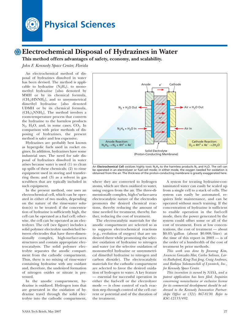
NASA Tech Briefs, May 2007 27
Physical Sciences
Electrochemical Disposal of Hydrazines in WaterThis method offers advantages of safety, economy, and scalability.John F. Kennedy Space Center, Florida
An electrochemical method of dis-posal of hydrazines dissolved in waterhas been devised. The method is appli-cable to hydrazine (N2H4), to mono-methyl hydrazine [also denoted byMMH or by its chemical formula,(CH3)HNNH2], and to unsymmetricaldimethyl hydrazine [also denotedUDMH or by its chemical formula,(CH3)2NNH2]. The method involves aroom-temperature process that convertsthe hydrazine to the harmless productsN2, H2O, and, in some cases, CO2. Incomparison with prior methods of dis-posing of hydrazines, the presentmethod is safer and less expensive.
Hydrazines are probably best knownas hypergolic fuels used in rocket en-gines. In addition, hydrazines have someindustrial uses. The need for safe dis-posal of hydrazines dissolved in waterarises because water is used (1) to cleanup spills of these chemicals; (2) to rinseequipment used in storing and transfer-ring them; and (3) as a solvent in gasscrubbers that are typically included insuch equipment.
In the present method, one uses anelectrochemical cell, which can be oper-ated in either of two modes, dependingon the nature of the rinse-water solu-tion(s) to be treated: if the concentra-tion of hydrazine is sufficiently high, thecell can be operated as a fuel cell; other-wise, the cell can be operated as an elec-trolyzer. The cell (see figure) includes asolid polymer electrolyte sandwiched be-tween electrodes that have three-dimen-sionally complex, high-surface-areastructures and contain appropriate elec-trocatalysts. The solid polymer elec-trolyte separates the anodic compart-ment from the cathodic compartment.Thus, there is no mixing of rinse-watercontaining hydrazine with any oxidantand, therefore, the undesired formationof nitrogen oxides or nitrate is pre-vented.
In the anodic compartment, hy-drazine is oxidized. Hydrogen ions thatare generated in the oxidation of hy-drazine travel through the solid elec-trolyte into the cathodic compartment,
where they are converted to hydrogenatoms, which are then oxidized to water,using oxygen from the air. The three-di-mensionally complex, high-sºurface-areaelectrocatalytic nature of the electrodespromotes the desired chemical reac-tions, thereby reducing the amount oftime needed for treatment, thereby, fur-ther, reducing the cost of treatment.
The electrocatalytic materials for theanodic compartment are selected so asto suppress electrochemical reactions(e.g., evolution of oxygen) that are un-desired there while promoting the selec-tive oxidation of hydrazine to nitrogenand water (or the selective oxidation ofmonomethyl hydrazine or unsymmetri-cal dimethyl hydrazine to nitrogen andcarbon dioxide). The electrocatalyticmaterials for the cathodic compartmentare selected to favor the desired oxida-tion of hydrogen to water. A key feature— essential for successful operation ineither the fuel-cell or the electrolyzermode — is close control of each reac-tion step through control of the cell cur-rent or potential and of the duration ofthe treatment.
A system for treating hydrazine-con-taminated water can easily be scaled upfrom a single cell to a stack of cells. Thesystem can easily be automated, re-quires little maintenance, and can beoperated without much training. If theconcentration of hydrazine is sufficientto enable operation in the fuel-cellmode, then the power generated by thesystem could offset some or all of thecost of treatment. Even at low concen-trations, the cost of treatment — about$0.03/gallon (about $0.008/liter) atthe time of this report in 2003 — is ofthe order of a hundredth of the cost oftreatment by prior methods.
This work was done by Jinseong Kim,Anuncia Gonzalez-Mar, Carlos Salinas, Lar-ris Rutheford, King-Tsai Jeng, Craig Andrews,and Ratlaya Yalamanchili of Lynntech, Inc.,for Kennedy Space Center.
This invention is owned by NASA, and apatent application has been filed. Inquiriesconcerning nonexclusive or exclusive licensefor its commercial development should be ad-dressed to the Kennedy Innovative Partner-ships Office at (321) 867-8130. Refer toKSC-12133/492.
e–
H+
Anode Cathode
Air + H2O Out
N2H4 + H2O In
N2 + H2O Out
Air In
Solid Electrolyte (Proton-Conducting Membrane)
Anode Reaction:N2H4 → N2 + 4H+ + 4e–
Cathode Reaction:O2 + 4H+ + 4e– → 2H2O
An Electrochemical Cell oxidizes highly toxic N2H4 to the harmless products N2 and H2O. The cell canbe operated in an electrolyzer or fuel-cell mode; in either mode, the oxygen needed for oxidation isobtained from the air. The thickness of the proton-conducting membrane is greatly exaggerated here.
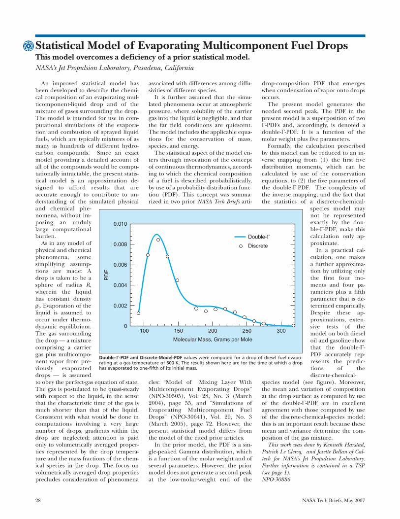
28 NASA Tech Briefs, May 2007
Statistical Model of Evaporating Multicomponent Fuel DropsThis model overcomes a deficiency of a prior statistical model.NASA’s Jet Propulsion Laboratory, Pasadena, California
An improved statistical model hasbeen developed to describe the chemi-cal composition of an evaporating mul-ticomponent-liquid drop and of themixture of gases surrounding the drop.The model is intended for use in com-putational simulations of the evapora-tion and combustion of sprayed liquidfuels, which are typically mixtures of asmany as hundreds of different hydro-carbon compounds. Since an exactmodel providing a detailed account ofall of the compounds would be compu-tationally intractable, the present statis-tical model is an approximation de-signed to afford results that areaccurate enough to contribute to un-derstanding of the simulated physicaland chemical phe-nomena, without im-posing an undulylarge computationalburden.
As in any model ofphysical and chemicalphenomena, somesimplifying assump-tions are made: Adrop is taken to be asphere of radius R,wherein the liquidhas constant densityρl. Evaporation of theliquid is assumed tooccur under thermo-dynamic equilibrium.The gas surroundingthe drop — a mixturecomprising a carriergas plus multicompo-nent vapor from pre-viously evaporateddrops — is assumedto obey the perfect-gas equation of state.The gas is postulated to be quasi-steadywith respect to the liquid, in the sensethat the characteristic time of the gas ismuch shorter than that of the liquid.Consistent with what would be done incomputations involving a very largenumber of drops, gradients within thedrop are neglected; attention is paidonly to volumetrically averaged proper-ties represented by the drop tempera-ture and the mass fractions of the chem-ical species in the drop. The focus onvolumetrically averaged drop propertiesprecludes consideration of phenomena
associated with differences among diffu-sivities of different species.
It is further assumed that the simu-lated phenomena occur at atmosphericpressure, where solubility of the carriergas into the liquid is negligible, and thatthe far field conditions are quiescent.The model includes the applicable equa-tions for the conservation of mass,species, and energy.
The statistical aspect of the model en-ters through invocation of the conceptof continuous thermodynamics, accord-ing to which the chemical compositionof a fuel is described probabilistically,by use of a probability distribution func-tion (PDF). This concept was summa-rized in two prior NASA Tech Briefs arti-
cles: “Model of Mixing Layer WithMulticomponent Evaporating Drops”(NPO-30505), Vol. 28, No. 3 (March2004), page 55, and “Simulations ofEvaporating Multicomponent FuelDrops” (NPO-30641), Vol. 29, No. 3(March 2005), page 72. However, thepresent statistical model differs fromthe model of the cited prior articles.
In the prior model, the PDF is a sin-gle-peaked Gamma distribution, whichis a function of the molar weight and ofseveral parameters. However, the priormodel does not generate a second peakat the low-molar-weight end of the
drop-composition PDF that emergeswhen condensation of vapor onto dropsoccurs.
The present model generates theneeded second peak. The PDF in thepresent model is a superposition of twoΓ-PDFs and, accordingly, is denoted adouble-Γ-PDF. It is a function of themolar weight plus five parameters.
Formally, the calculation prescribedby this model can be reduced to an in-verse mapping from (1) the first fivedistribution moments, which can becalculated by use of the conservationequations, to (2) the five parameters ofthe double-Γ-PDF. The complexity ofthe inverse mapping, and the fact thatthe statistics of a discrete-chemical-
species model maynot be representedexactly by the dou-ble-Γ-PDF, make thiscalculation only ap-proximate.
In a practical cal-culation, one makesa further approxima-tion by utilizing onlythe first four mo-ments and four pa-rameters plus a fifthparameter that is de-termined empirically.Despite these ap-proximations, exten-sive tests of themodel on both dieseloil and gasoline showthat the double-Γ-PDF accurately rep-resents the predic-tions of thediscrete-chemical-
species model (see figure). Moreover,the mean and variation of compositionat the drop surface as computed by useof the double-Γ-PDF are in excellentagreement with those computed by useof the discrete-chemical-species model:this is an important result because thesemean and variance determine the com-position of the gas mixture.
This work was done by Kenneth Harstad,Patrick Le Clercq, and Josette Bellan of Cal-tech for NASA’s Jet Propulsion Laboratory.Further information is contained in a TSP(see page 1).NPO-30886
Double-Γ
Discrete
100
0.002
0
0.004
0.006
0.008
0.010
150 200
Molecular Mass, Grams per Mole
PD
F
250 300
Double-ΓΓ-PDF and Discrete-Model-PDF values were computed for a drop of diesel fuel evapo-rating at a gas temperature of 600 K. The results shown here are for the time at which a drophas evaporated to one-fifth of its initial mass.
NASA Tech Briefs, May 2007 29
An improved nozzle has been devel-oped to replace nozzles used previouslyin an apparatus that generates a substan-tially unidirectional beam of moleculespassing through a vacuum at speeds ofseveral kilometers per second. The needto replace the previous nozzles arosefrom a complex set of causes that can besummarized as follows: (1) The previous nozzles had short oper-
ational lifetimes because it was nec-essary to fabricate them from com-ponents made of several differentmaterials that, when used together,do not last long at the high operat-ing temperatures needed to gener-ate the requisite high molecularspeeds and
(2) To protect the vacuum chamberfrom excessive heating, it was neces-sary to surround the operating noz-zle with a cooling shroud thatrobbed the nozzle of reflectedheater power and thereby con-tributed to energy inefficiency.
The basic principle of operation ofthe apparatus is the same for both theprevious and the present nozzle designs.The main working part of the nozzle isessentially a cylinder that is closed ex-cept that there is an inlet for a pressur-ized gas and, at one end, the cylinder isclosed by a disk that contains a narrowcentral hole that serves as an outlet. Thecylinder is heated to increase the ther-mal speeds of the gas molecules into thedesired high-speed range. Heated, pres-surized gas escapes through the outletinto a portion of the vacuum chamberthat is separated, by a wall, from the rest
of the vacuum chamber. In this portionof the vacuum chamber, the gas under-goes a free jet expansion. Most of the ex-panded gas is evacuated and thus doesnot become part of the molecular beam.A small fraction of the expanded beampasses through a narrow central orificein the wall and thereby becomes a nee-dle-thin molecular beam in the portionof the vacuum on the downstream sideof the wall.
In a nozzle of the previous design, thecylinder was made of molybdenum, andthe disk with the outlet hole, also madeof molybdenum, was welded onto thecylinder at one end. In the improvednozzle, the cylinder and the disk at oneend containing the narrow outlet holeare made of a single piece of silicon car-bide. In a nozzle of the previous design,the molybdenum cylinder was sur-rounded by an alumina electrical-insula-tion cylinder that was, in turn, sur-rounded by a silicon carbide cylinderthat served as an electrical resistanceheater. In the improved nozzle, the sili-con carbide cylinder serves as its ownelectrical resistance heater.
In the improved nozzle, the siliconcarbide cylinder is brazed to a molybde-num fitting that is brazed to a stainless-steel fitting that is electron-beam weldedonto a length of stainless-steel tubing.Electrodes made of tungsten wire are at-tached to the ends of the silicon carbidecylinder by means of two-piece molyb-denum hinge clamps, wherein the elec-trodes serve as the hinge pins. Sufficientclearance is provided between eachmolybdenum clamp and the SiC cylin-
der nozzle to accommodate a piece ofgraphite tape that both cushions and en-sures a high degree of electrical contact.To reflect some heater power to the SiCcylinder and thereby both increase en-ergy efficiency and reduce heating ofthe vacuum chamber, the nozzle as de-scribed thus far is surrounded by a radi-ation shield in the form of 12 concentriccylindrical layers of 50-µm-thick tung-sten foil that are dimpled to maintaingaps between successive layers. The radi-ation shield is cooled by a circulationsubsystem.
The nozzle has been tested using a gasmixture comprising 1 percent argonand 99 percent hydrogen at feed pres-sures up to 450 psi (≈3.1 MPa) and tem-peratures up to 2,000 °C. In one test at1,600 °C, the speed of the argon fractionof the beam was observed to be 3.3km/s. On the basis of performance datafrom the tests, it has been estimated thatthe nozzle would have unlimited opera-tional lifetime at room temperature,could operate for many hundreds ofhours at 1,000 °C, and could operate forat least 100 hours at 1,500 °C. At operat-ing temperatures above 1,500 °C, thenozzle is vulnerable to clogging, thoughin the absence of oxygen, it may still becapable of operating for many hours.
This work was done by Steven Cagiano ofGoddard Space Flight Center; Robert Abell ofSwales Aerospace; Edward Patrick and MirlBendt of Honeywell Technical Services, Inc.;and Cynthia Gundersen of AMU Engineer-ing, Inc. Further information is contained ina TSP (see page 1).GSC-14837-1.
Resistively Heated SiC Nozzle for Generating Molecular BeamsThis nozzle is more durable and efficient relative to its predecessors.Goddard Space Flight Center, Greenbelt, Maryland
A carrier structure made from a singlesilicon substrate is the basis of a compact,lightweight, relatively inexpensive pack-age that holds the main optical/elec-tronic coupling components of a pho-tonic millimeter-wave receiver based on alithium niobate resonator disk. The de-sign of the package is simple and pro-vides for precise relative placement of op-
tical components, eliminating the needfor complex, bulky positioning mecha-nisms like those commonly used to alignoptical components to optimize focusand coupling. Although a prototype ofthe package was fabricated as a discreteunit, the design is amenable to integra-tion of the package into a larger photonicand/or electronic receiver system.
The components (see figure) includea lithium niobate optical resonator diskof 5-mm diameter and ≈200-µm thick-ness, positioned adjacent to a millime-ter-wave resonator electrode. Othercomponents include input and outputcoupling prisms and input and outputoptical fibers tipped with ball lenses forfocusing and collimation, respectively.
Compact Packaging of Photonic Millimeter-Wave Receiver Bulky positioning mechanisms are not needed. John H. Glenn Research Center, Cleveland, Ohio
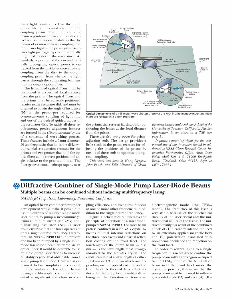
30 NASA Tech Briefs, May 2007
Laser light is introduced via the inputoptical fiber and focused into the inputcoupling prism. The input couplingprism is positioned near (but not in con-tact with) the resonator disk so that bymeans of evanescent-wave coupling, theinput laser light in the prism gives rise tolaser light propagating circumferentiallyin guided modes in the resonator disk.Similarly, a portion of the circumferen-tially propagating optical power is ex-tracted from the disk by evanescent-wavecoupling from the disk to the outputcoupling prism, from whence the lightpasses through the collimating ball lensinto the output optical fiber.
The lens-tipped optical fibers must bepositioned at a specified focal distancefrom the prisms. The optical fibers andthe prisms must be correctly positionedrelative to the resonator disk and must beoriented to obtain the angle of incidence(55° in the prototype) required forevanescent-wave coupling of light intoand out of the desired guided modes inthe resonator disk. To satisfy all these re-quirements, precise alignment featuresare formed in the silicon substrate by useof a conventional wet-etching process.These features include a 5-mm-diameter,50-µm-deep cavity that holds the disk; twotrapezoidal-cross-section recesses for theprisms; and two grooves that hold the op-tical fibers at the correct positions and an-gles relative to the prisms and disk. Thefiber grooves contain abrupt tapers, near
the prisms, that serve as hard stops for po-sitioning the lenses at the focal distancefrom the prisms.
There are also two grooves for prism-adjusting rods. The design provides alittle slack in the prism recesses for ad-justing the positions of the prisms bymeans of these rods to optimize the op-tical coupling.
This work was done by Hung Nguyen,John Pouch, and Felix Miranda of Glenn
Research Center, and Anthony F. Levi of theUniversity of Southern California. Furtherinformation is contained in a TSP (seepage 1).
Inquiries concerning rights for the com-mercial use of this invention should be ad-dressed to NASA Glenn Research Center, In-novative Partnerships Office, Attn: SteveFedor, Mail Stop 4–8, 21000 BrookparkRoad, Cleveland, Ohio 44135. Refer toLEW-17694-1.
An optical beam combiner now underdevelopment would make it possible touse the outputs of multiple single-modelaser diodes to pump a neodymium: yt-trium aluminum garnet (Nd:YAG) non-planar ring oscillator (NPRO) laserwhile ensuring that the laser operates atonly a single desired frequency. Hereto-fore, an Nd:YAG NPRO like the presentone has been pumped by a single multi-mode laser-diode beam delivered via anoptical fiber. It would be desirable to usemultiple pump laser diodes to increasereliability beyond that obtainable from asingle pump laser diode. However, as ex-plained below, simplistically couplingmultiple multimode laser-diode beamsthrough a fiber-optic combiner wouldentail a significant reduction in cou-
pling efficiency, and lasing would occurat one or more other frequencies in ad-dition to the single desired frequency.
Figure 1 schematically illustrates theprinciple of operation of a laser-diode-pumped Nd:YAG NPRO. The laser beampath is confined in a Nd:YAG crystal bymeans of total internal reflections onthe three back facets and a partial-reflec-tion coating on the front facet. Thewavelength of the pump beam — 808nm — is the wavelength most stronglyabsorbed by the Nd:YAG crystal. Thecrystal can lase at a wavelength of either1,064 nm or 1,319 nm — which one de-pending on the optical coating on thefront facet. A thermal lens effect in-duced by the pump beam enables stablelasing in the lowest-order transverse
electromagnetic mode (the TEM00
mode). The frequency of this laser isvery stable because of the mechanicalstability of the laser crystal and the uni-directional nature of the lasing. The uni-directionality is a result of the combinedeffects of (1) a Faraday rotation inducedby an externally applied magnetic fieldand (2) polarization associated withnon-normal incidence and reflection onthe front facet.
In order to restrict lasing to a singlefrequency, it is necessary to confine thepump beam within the region occupiedby the TEM00 mode of the NPRO laserbeam near the front facet inside thecrystal. In practice, this means that thepump beam must be focused to within agiven solid angle (Ω) and area (A). [If a
Diffractive Combiner of Single-Mode Pump Laser-Diode BeamsMultiple beams can be combined without inducing multifrequency lasing.NASA’s Jet Propulsion Laboratory, Pasadena, California
Light PropagatingCircumferentially in
Resonator Disk
Light PropagatingCircumferentially in
Resonator Disk
Millimeter-WaveResonator Electrode
OpticalResonator Disk
Laser LightOutLaser Light
In
SiliconSubstrate
Prism-AdjustingRod in Groove
Prism-AdjustingRod in Groove
Prism-AdjustingRod in Groove
Prism-AdjustingRod in Groove
OutputLight Beam
InputLight Beam
Optical Fiber inGroove
Input Optical Fiber inGroove
Optical Fiber inGroove
Ball Lens
Ball Lens
Output CouplingPrism
Input CouplingPrism
Optical Components of a millimeter-wave photonic receiver are kept in alignment by mounting themin precise recesses in a silicon substrate.
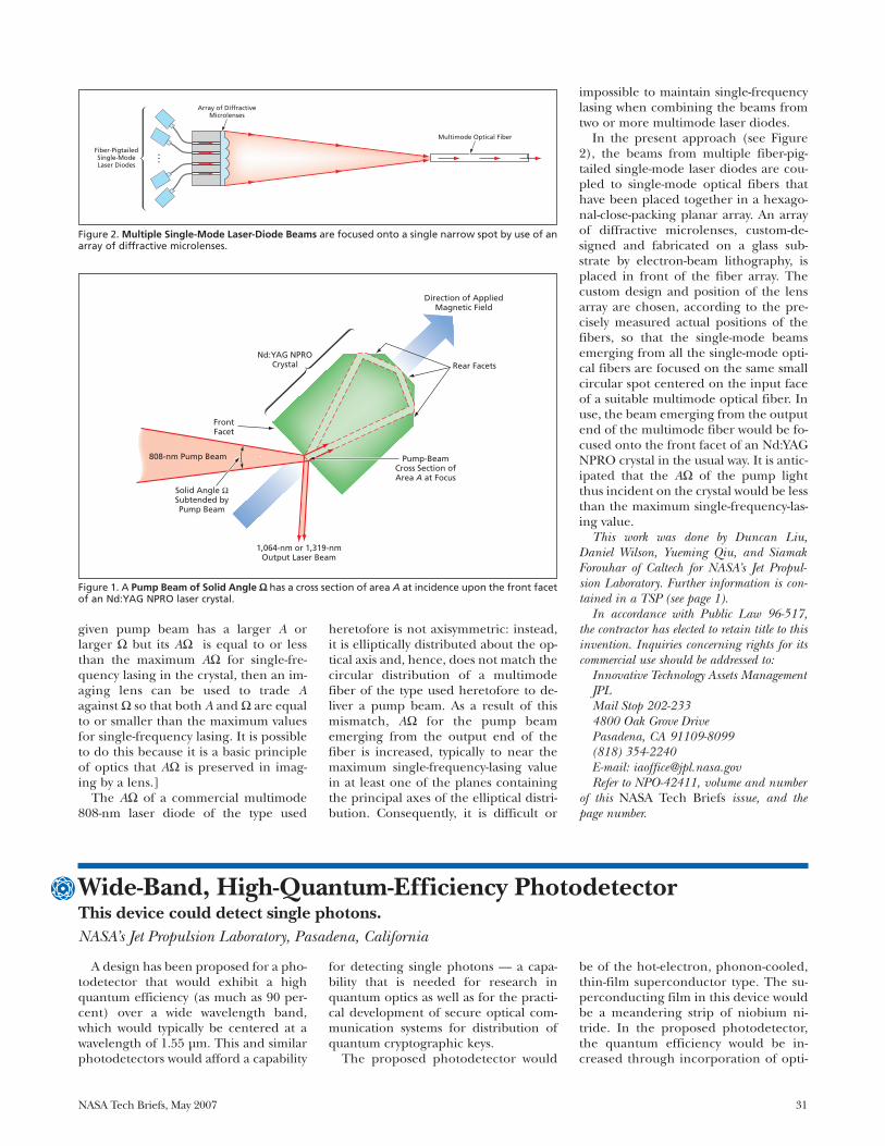
NASA Tech Briefs, May 2007 31
given pump beam has a larger A orlarger Ω but its AΩ is equal to or lessthan the maximum AΩ for single-fre-quency lasing in the crystal, then an im-aging lens can be used to trade Aagainst Ω so that both A and Ω are equalto or smaller than the maximum valuesfor single-frequency lasing. It is possibleto do this because it is a basic principleof optics that AΩ is preserved in imag-ing by a lens.]
The AΩ of a commercial multimode808-nm laser diode of the type used
heretofore is not axisymmetric: instead,it is elliptically distributed about the op-tical axis and, hence, does not match thecircular distribution of a multimodefiber of the type used heretofore to de-liver a pump beam. As a result of thismismatch, AΩ for the pump beamemerging from the output end of thefiber is increased, typically to near themaximum single-frequency-lasing valuein at least one of the planes containingthe principal axes of the elliptical distri-bution. Consequently, it is difficult or
impossible to maintain single-frequencylasing when combining the beams fromtwo or more multimode laser diodes.
In the present approach (see Figure2), the beams from multiple fiber-pig-tailed single-mode laser diodes are cou-pled to single-mode optical fibers thathave been placed together in a hexago-nal-close-packing planar array. An arrayof diffractive microlenses, custom-de-signed and fabricated on a glass sub-strate by electron-beam lithography, isplaced in front of the fiber array. Thecustom design and position of the lensarray are chosen, according to the pre-cisely measured actual positions of thefibers, so that the single-mode beamsemerging from all the single-mode opti-cal fibers are focused on the same smallcircular spot centered on the input faceof a suitable multimode optical fiber. Inuse, the beam emerging from the outputend of the multimode fiber would be fo-cused onto the front facet of an Nd:YAGNPRO crystal in the usual way. It is antic-ipated that the AΩ of the pump lightthus incident on the crystal would be lessthan the maximum single-frequency-las-ing value.
This work was done by Duncan Liu,Daniel Wilson, Yueming Qiu, and SiamakForouhar of Caltech for NASA’s Jet Propul-sion Laboratory. Further information is con-tained in a TSP (see page 1).
In accordance with Public Law 96-517,the contractor has elected to retain title to thisinvention. Inquiries concerning rights for itscommercial use should be addressed to:
Innovative Technology Assets ManagementJPLMail Stop 202-2334800 Oak Grove DrivePasadena, CA 91109-8099(818) 354-2240E-mail: [email protected] to NPO-42411, volume and number
of this NASA Tech Briefs issue, and thepage number.
Direction of AppliedMagnetic Field
Nd:YAG NPROCrystal
1,064-nm or 1,319-nmOutput Laser Beam
Pump-BeamCross Section ofArea A at Focus
Rear Facets
FrontFacet
808-nm Pump Beam
Figure 1. A Pump Beam of Solid Angle ΩΩ has a cross section of area A at incidence upon the front facetof an Nd:YAG NPRO laser crystal.
Fiber-PigtailedSingle-ModeLaser Diodes
Array of DiffractiveMicrolenses
Multimode Optical Fiber
Figure 2. Multiple Single-Mode Laser-Diode Beams are focused onto a single narrow spot by use of anarray of diffractive microlenses.
A design has been proposed for a pho-todetector that would exhibit a highquantum efficiency (as much as 90 per-cent) over a wide wavelength band,which would typically be centered at awavelength of 1.55 µm. This and similarphotodetectors would afford a capability
for detecting single photons — a capa-bility that is needed for research inquantum optics as well as for the practi-cal development of secure optical com-munication systems for distribution ofquantum cryptographic keys.
The proposed photodetector would
be of the hot-electron, phonon-cooled,thin-film superconductor type. The su-perconducting film in this device wouldbe a meandering strip of niobium ni-tride. In the proposed photodetector,the quantum efficiency would be in-creased through incorporation of opti-
Wide-Band, High-Quantum-Efficiency PhotodetectorThis device could detect single photons.NASA’s Jet Propulsion Laboratory, Pasadena, California
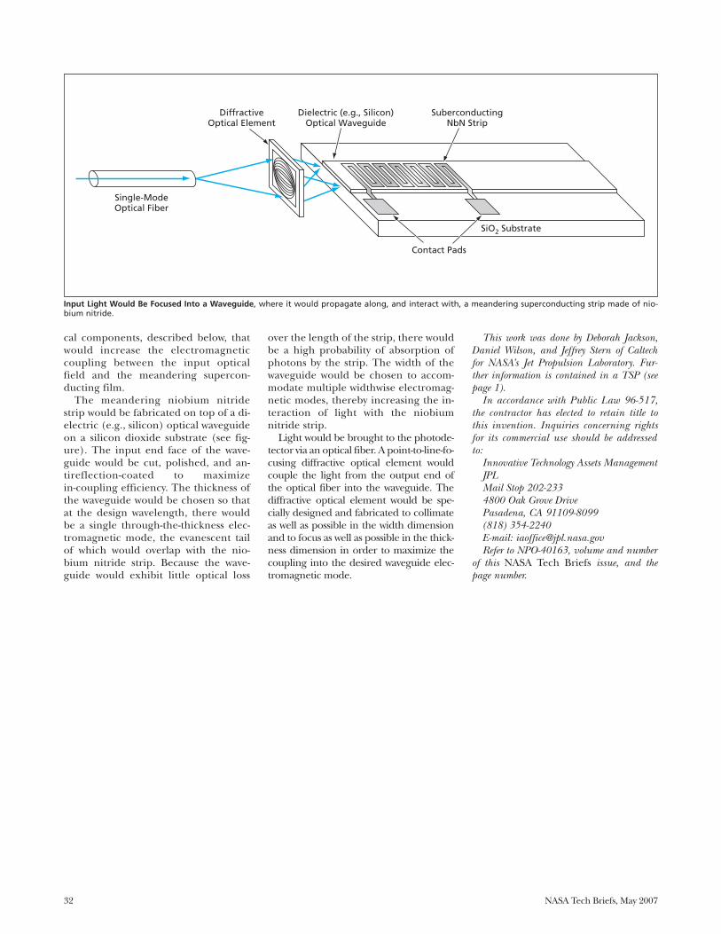
32 NASA Tech Briefs, May 2007
cal components, described below, thatwould increase the electromagneticcoupling between the input opticalfield and the meandering supercon-ducting film.
The meandering niobium nitridestrip would be fabricated on top of a di-electric (e.g., silicon) optical waveguideon a silicon dioxide substrate (see fig-ure). The input end face of the wave-guide would be cut, polished, and an-tireflection-coated to maximizein-coupling efficiency. The thickness ofthe waveguide would be chosen so thatat the design wavelength, there wouldbe a single through-the-thickness elec-tromagnetic mode, the evanescent tailof which would overlap with the nio-bium nitride strip. Because the wave-guide would exhibit little optical loss
over the length of the strip, there wouldbe a high probability of absorption ofphotons by the strip. The width of thewaveguide would be chosen to accom-modate multiple widthwise electromag-netic modes, thereby increasing the in-teraction of light with the niobiumnitride strip.
Light would be brought to the photode-tector via an optical fiber. A point-to-line-fo-cusing diffractive optical element wouldcouple the light from the output end ofthe optical fiber into the waveguide. Thediffractive optical element would be spe-cially designed and fabricated to collimateas well as possible in the width dimensionand to focus as well as possible in the thick-ness dimension in order to maximize thecoupling into the desired waveguide elec-tromagnetic mode.
This work was done by Deborah Jackson,Daniel Wilson, and Jeffrey Stern of Caltechfor NASA’s Jet Propulsion Laboratory. Fur-ther information is contained in a TSP (seepage 1).
In accordance with Public Law 96-517,the contractor has elected to retain title tothis invention. Inquiries concerning rightsfor its commercial use should be addressedto:
Innovative Technology Assets ManagementJPLMail Stop 202-2334800 Oak Grove DrivePasadena, CA 91109-8099(818) 354-2240E-mail: [email protected] to NPO-40163, volume and number
of this NASA Tech Briefs issue, and thepage number.
Single-ModeOptical Fiber
DiffractiveOptical Element
Dielectric (e.g., Silicon)Optical Waveguide
SuberconductingNbN Strip
SiO2 Substrate
Contact Pads
Input Light Would Be Focused Into a Waveguide, where it would propagate along, and interact with, a meandering superconducting strip made of nio-bium nitride.
NASA Tech Briefs, May 2007 33
A model predictive control (MPC) al-gorithm that differs from prior MPC al-gorithms has been developed for con-trolling an uncertain nonlinear system.This algorithm guarantees the resolv-ability of an associated finite-horizon op-timal-control problem in a receding-horizon implementation. Given afeasible solution to the finite-horizonoptimal control problem at an initialtime, resolvability implies the ability tosolve the optimal control problem atsubsequent times.
Originally developed for the controlof spacecraft in the proximity of smallcelestial bodies, the algorithm can alsobe applied to other systems (such as in-dustrial and automotive systems) forwhich robust feedback control may berequired. The algorithm consists of afeedforward and a feedback component.The feedforward part is computed by
the on-line solution of the finite-horizonoptimal control problem with the nomi-nal system dynamics, with a relaxation ofthe initial state constraint at each com-putation.
The feedback component makes thisrelaxation possible, which in turn guar-antees resolvability and asymptotic sta-bility once an initial feasible solution isobtained at the start of a maneuver. Thefeedback part involves off-line design ofa feedback control policy based on theuncertainty bounds in the dynamicalmodel of the system. Consequently, thisalgorithm is robust to system uncertain-ties that are explicitly accounted for inthe design of the feedback portion ofthe control input.
This explicit characterization of the ro-bustness to the uncertainties (which caneasily be extended to external distur-bances) is particularly desirable in a real-
time autonomous control application.Furthermore, the ability to solve for anopen-loop trajectory during a maneuverenables model updates (possibly basedon real-time information) into the con-trol problem to reduce model uncer-tainty and improve optimality for theopen-loop trajectory. The algorithm hasbeen shown to be robustly stabilizingunder state and control constraints with aregion of attraction composed of initialstates for which solution of the finite-hori-zon optimal control problem is feasible.
This work was done by A. Behçet Açkmeçeand John M. Carson III of Caltech for NASA’sJet Propulsion Laboratory. Further informa-tion is contained in a TSP (see page 1).
The software used in this innovation isavailable for commercial licensing. Pleasecontact Karina Edmonds of the CaliforniaInstitute of Technology at (626) 395-2322.Refer to NPO-42754.
A Robustly Stabilizing Model Predictive Control AlgorithmThe algorithm can be applied to industrial and automotive systems.NASA’s Jet Propulsion Laboratory, Pasadena, California
Information Sciences
A mathematical model describes theevaporation of drops of a hydrocarbonliquid composed of as many as hundredsof chemical species. The model is in-tended especially for application to anyof several types of kerosenes commonlyused as fuels. Like evaporating-multi-component-fuel-drop models describedin several previous NASA Tech Briefs arti-cles, the present model invokes the con-cept of continuous thermodynamics, ac-cording to which the chemicalcomposition of the evaporating multi-component liquid is described by use ofa probability distribution function(PDF). However, as described below, thepresent model is more generally applica-ble than is its immediate predecessor.
The present model is built on the onereported in “Statistical Model of Evapo-rating Multicomponent Fuel Drops”(NPO-30886), which appears elsewhere
in this issue. To recapitulate: The PDF inthat model is a superposition of two func-tions and, accordingly, is denoted a dou-ble PDF. It is a function of the molecularweight plus five other parameters. Unfor-tunately, some of those other parametersdepend on the class of homologous hy-drocarbon species, so that it becomesnecessary to have a double PDF for eachsuch class entering the fuel composition.The introduction of multiple doublePDFs would make the computation verycumbersome, negating the advantage ofthe continuous-thermodynamics formu-lation. The derivation of the presentmodel is driven by the concept of a uni-fied thermodynamic representation ofthree classes of homologous hydrocar-bons (alkanes, naphthenes, and aromat-ics) that constitute the principal compo-nents of kerosenes. Somewhat morespecifically, it is sought to characterize
the hydrocarbons in each homologousseries by unified reference temperatures,pressures, and other parameters that de-pend only on molecular weights andthermodynamic quantities.
The derivation leads to a new versionof the double PDF, in which the squareroot of the molecular weight occupiesthe position previously occupied by themolecular weight and other parametersare modified accordingly. By design, thisversion of the double PDF applies to thethree major homologous series inkerosene; hence, it is not necessary touse multiple double PDFs. An additionaladvantage of this formulation is that it isvalid over the subcritical region in thepressure range from 1 to 15 bars (0.1 to1.5 MPa).
The model has been tested on threekerosenes used as aircraft and rocketfuels: Jet A, JP-7, and RP-1. The present
Modeling Evaporation of Drops of Different KerosenesOne model applies to all three classes of hydrocarbon constituents.NASA’s Jet Propulsion Laboratory, Pasadena, California

version of the double PDF has been fittedto the discrete species distributions ofthese kerosenes and extensive calcula-
tions of evaporation of isolated drops per-formed. The results show that under theassumption of a quasi-steady gas phase, a
relation known in the literature as the D 2
law (pertaining to the rate of decrease ofthe square of the drop diameter) is recov-ered after an initial drop-heating tran-sient. A related quantity known in the lit-erature as the asymptotic evaporationrate constant has been found to be an in-creasing function of the far-field temper-ature and pressure, a complex functionof far-field composition, and a weak func-tion of the difference between the drop-surface and far-field vapor molar frac-tions. In a comparison between resultsobtained (a) under the assumption thatthe interior of the drop is well mixed (the“wm” assumption) and (b) under the as-sumption that the drop can evaporate ei-ther in a well-mixed mode or at unchang-ing (frozen) composition (the “wm-fc”assumption), it was found that the differ-ences between the asymptotic evapora-tion rate constants under the two assump-tions is within the range of uncertainty inthe transport properties (see figure).
This work was done by Josette Bellan andKenneth Harstad of Caltech for NASA’s JetPropulsion Laboratory. Further information iscontained in a TSP (see page 1).NPO-40437
34 NASA Tech Briefs, May 2007
Jet AJP-7RP-1Jet AJP-7RP-1
Far-Field Pressure, Bars
Asy
mp
toti
c Ev
apo
rati
on
Rat
e C
on
stan
t, m
m2 /s
0 5 10 15
0.32
0.30
0.28
0.26
0.24
0.22
0.20
0.18
The Asymptotic Evaporation Rate Constants of three kerosenes as a function of far-field pressurewere computed for a far-field temperature of 1,000 K and zero far-field vapor fraction.
NASA Tech Briefs, May 2007 35
Books & Reports
Development of Vapor-Phase Catalytic AmmoniaRemoval System
A report describes recent accomplish-ments of a continuing effort to developthe vapor-phase catalytic ammonia re-moval (VPCAR) process for recyclingwastewater for consumption by humansaboard a spacecraft in transit to Mars.The VPCAR process is implemented by asystem of highly integrated design inwhich some power consumption is ac-cepted as a cost of minimizing the vol-ume and mass of a wastewater-process-ing system and eliminating the need toresupply water. The core of the system isa wiped-film rotating-disk (WFRD) evap-orator, which removes inorganic saltsand nonvolatile organic compoundsfrom the wastewater stream and concen-trates these contaminants into a recycle-and-bleed stream. The WFRD evapora-tor is also part of a subsystem that distillswater from the wastewater stream. Thissubsystem operates in a vacuum-vapor/compression distillation configu-ration in the temperature range from 20to 65 °C. Volatile organic compoundsand ammonia, distilled along with water,are oxidized to CO2, H2O, and N2O in apacked-bed, high-temperature catalyticreactor placed at the outlet of the vapor-phase compressor of the distillation sub-system. A VPCAR engineering demon-stration unit is expected to be includedin a human-rated simulation of a mis-sion to Mars.
This work was done by Michael Flynn,John Fisher, and Mark Kliss of Ames Re-search Center; Bruce Borchers of Orbital Sci-ences Corp.; Badawi Tleimat and MaherTleimat of Water Reuse Technology Inc.; andGregory Quinn, James Fort, Tim Nalette,Gale Baker, and Joseph Genovese of HamiltonSundstrand Space Systems International,Inc. Further information is contained in aTSP (see page 1).
Inquiries concerning rights for the commer-cial use of this invention should be addressedto the Ames Technology Partnerships Divisionat (650) 604-2954. Refer to ARC-14607-1.
Several Developments inSpace Tethers
Five reports address different aspectsof development of tethers to be deployedfrom spacecraft in orbit around the
Earth. The first report discusses proposedoptoelectronic tracking of retroreflectiveobjects located at intervals or of retrore-flective coats along the entire length of atether to measure lateral motions. Thesecond report describes digitally con-trolled spooling machinery that retractsor extends a tape tether at controlledspeed and tension in the spool isolatedfrom uncontrolled tension on the out-side. The third report discusses part ofthis machinery that pivots to accommo-date misalignments between the de-ployed and spooled portions of the tetherand contains rollers used to exert tensionand speed control. The fourth report dis-cusses aspects of designs of proposedelectrodynamic tethers, which would beelectrically conductive and would interactwith the magnetic field of the Earth toexert forces to modify orbits of deployingspacecraft. The fifth report discusses elec-trical aspects of designs of electrody-namic tape tethers, including the use ofsolar cells or motional electromagneticforce to generate currents in tethers andthe use of electron emitters and electronand ion collectors at opposite ends oftethers to make electrical contact withthe thin plasma in surrounding space.
This work was done by Andrew Santangeloand Rich Sturmfels of The Michigan TechnicCorp. and Neal Rothwell of Double R Con-trols for Marshall Space Flight Center. Fur-ther information is contained in a TSP (seepage 1).MFS-31822/4/6/7/30
Design Concept for a Nu-clear Reactor-Powered MarsRover
A report presents a design concept foran instrumented robotic vehicle (rover)to be used on a future mission of explo-ration of the planet Mars. The design in-corporates a nuclear fission power sys-tem to provide long range, long life, andhigh power capabilities unachievablethrough the use of alternative solar orradioisotope power systems. The con-cept described in the report draws onprevious rover designs developed for the2009 Mars Science laboratory (MSL)mission to minimize the need for newtechnology developments.
The surface fission power system thatwould be used consists of a 15 kW (ther-mal) heat-pipe-cooled reactor coupled
with a Stirling generator to provide 3kW of electrical power. This power sys-tem would be compact enough to fitreadily into prior rover chassis con-cepts, allowing further adaptation ofpreviously designed MSL elements, in-cluding the aeroshell and pallet landersystem, with modifications to supportthe significant mass added by the nu-clear reactor and its associated shield-ing. The estimated mass of the fissionpower system, including its mission-spe-cific shielding, is 1,169 kg.
This work was done by John Elliott of Cal-tech, Dave Poston of Los Alamos NationalLaboratory, and Ron Lipinski of Sandia Na-tional Laboratory for NASA’s Jet PropulsionLaboratory. Further information is containedin a TSP (see page 1). NPO-30865
Formation-Initialization Al-gorithm for N Spacecraft
A paper presents an algorithm to ini-tialize a formation of N distributedspacecraft in deep space. Such forma-tions will enable variable-baseline inter-ferometers in future NASA missions de-signed to study the structure and originof the universe. The algorithm de-scribed in the paper reflects some basicassumptions: 1. Each spacecraft is capable of omnidi-
rectional radio communication withany other spacecraft,
2. Each spacecraft is equipped with alimited field-of-view sensor relative po-sition sensor (RPS) to measure therelative positions and velocities ofother formation members, and
3. Spacecraft maneuvers must satisfySun-angle pointing constraints toshield sensitive optical equipmentfrom direct sunlight.The formation initialization algo-
rithm proceeds by first dividing thespacecraft into two groups with anti-par-allel RPS sensor boresights. Next, thespacecraft perform a three-phase (in-plane, out-of-plane, and near-field) skysearch involving synchronized maneu-vers to ensure full sky coverage whilemaintaining front-to-front, simultaneousRPS sensor lock. During the sky search,the spacecraft are grouped into twoclasses of sub-formations. The initializa-tion problem is then reduced to the sim-pler problem of joining the sub-forma-tions. The paper includes an analytical
36 NASA Tech Briefs, May 2007
proof that the algorithm is guaranteedto initialize the formation as required.
This work was done by Scott Ploen, DanielScharf, and Fred Hadaegh of Caltech forNASA’s Jet Propulsion Laboratory. Further in-formation is contained in a TSP (see page 1).
The software used in this innovation isavailable for commercial licensing. Pleasecontact Karina Edmonds of the CaliforniaInstitute of Technology at (626) 395-2322.Refer to NPO-43040.
DNSs of MulticomponentGaseous and Drop-LadenMixing Layers AchievingTransition to Turbulence
A paper describes direct numericalsimulations (DNSs) of three-dimen-sional mixing-layer flows undergoingtransition to turbulence; the mixing lay-ers may or may not be laden with evapo-rating liquid drops. In contrast to moststudies in this field, the general case is
investigated here where both the gasand the liquid drops’ composition en-compasses a very large number ofspecies. The simulations were per-formed using a mathematical model dis-cussed in several prior NASA Tech Briefsarticles; the prior studies described alaminar mixing layer, whereas the pres-ent study describes a mixing layer thathas all attributes of turbulence. Themodel includes governing equations inan Eulerian and a Lagrangian referenceframe for the gas and drops, respectively.To mathematically describe the myriadof species, the model relies on continu-ous thermodynamics concepts. Thepaper succinctly reiterates the modeland discusses results of the new numeri-cal simulations. Comparisons are per-formed with previous single-species sim-ilar simulations and with the laminarsimulations using the same model. Thepaper presents several conclusions, themain one being that differences be-
tween single- and multi-species turbu-lent flows having the same initial condi-tions are so significant that neither ex-periments on, nor theoretical studies of,single-species flows are adequate as sur-rogates for studies of multi-species flows.
This work was done by Josette Bellan andLaurent Selle of Caltech for NASA’s JetPropulsion Laboratory. Further information iscontained in a TSP (see page 1).
In accordance with Public Law 96-517,the contractor has elected to retain title to thisinvention. Inquiries concerning rights for itscommercial use should be addressed to:
Innovative Technology Assets ManagementJPLMail Stop 202-2334800 Oak Grove DrivePasadena, CA 91109-8099(818) 354-2240E-mail: [email protected] to NPO-42632, volume and number
of this NASA Tech Briefs issue, and thepage number.


National Aeronautics andSpace Administration