
Technology-Driven, Highly-Scalable Dragonfly Topology · two methods gives throughput and latency...
12
Technology-Driven, Highly-Scalable Dragonfly Topology * John Kim Northwestern University Evanston, IL 60208 [email protected] William J. Dally Stanford University Stanford, CA 94305 [email protected] Steve Scott Cray Inc. Chippewa Falls, WI 54729 [email protected] Dennis Abts Google Inc. [email protected] Abstract Evolving technology and increasing pin-bandwidth moti- vate the use of high-radix routers to reduce the diameter, la- tency, and cost of interconnection networks. High-radix net- works, however, require longer cables than their low-radix counterparts. Because cables dominate network cost, the num- ber of cables, and particularly the number of long, global ca- bles should be minimized to realize an efficient network. In this paper, we introduce the dragonfly topology which uses a group of high-radix routers as a virtual router to increase the effective radix of the network. With this organization, each minimally routed packet traverses at most one global channel. By reducing global channels, a dragonfly reduces cost by 20% compared to a flattened butterfly and by 52% compared to a folded Clos network in configurations with ≥ 16K nodes. We also introduce two new variants of global adaptive rout- ing that enable load-balanced routing in the dragonfly. Each router in a dragonfly must make an adaptive routing decision based on the state of a global channel connected to a different router. Because of the indirect nature of this routing decision, conventional adaptive routing algorithms give degraded per- formance. We introduce the use of selective virtual-channel discrimination and the use of credit round-trip latency to both sense and signal channel congestion. The combination of these two methods gives throughput and latency that approaches that of an ideal adaptive routing algorithm. 1 Introduction Interconnection networks are a critical component of mod- ern computer systems. From large scale systems [1, 19, 27] to multicore architectures [17, 33], the interconnection net- work that connects processors and memory modules signifi- cantly impacts the overall performance and cost of the sys- tem. As processor and memory performance continues to in- crease, multicomputer interconnection networks are becoming even more critical as they largely determine the bandwidth and latency of remote memory access. A good interconnection network is designed around the ca- pabilities and constraints of available technology. Increasing * This work was done while John Kim was a Ph.D. student at Stanford University and Dennis Abts was with Cray Inc. 0 200 400 600 800 1000 1200 1400 1600 100 1,000 10,000 100,000 1,000,000 Network Size (N) Radix (k) Figure 1. Radix (k) of the routers required to scale the network (N) if only one global hop is required for each packet. router pin bandwidth, for example, has motivated the use of high-radix routers [15] in which the increased bandwidth is used to increase the number of ports per router, rather than maintaining a small number of ports and increasing the band- width per port. The Cray BlackWidow system [1], one of the first systems to employ a high-radix network, uses a variant of the folded-Clos topology and radix-64 routers [26] — a significant departure from previous low-radix 3-D torus net- works [27]. Recently, the advent of economical optical sig- nalling [12, 22] enables topologies with long channels. How- ever, these long optical channels are significantly more expen- sive than short electrical channels. In this paper, we introduce the dragonfly 1 topology that exploits emerging optical sig- naling technology by grouping routers to further increase the effective radix of the network. The topology of an interconnection network largely deter- mines both the performance and the cost of the network [8]. Network cost is dominated by the cost of channels, and in particular the cost of the long, global, inter-cabinet channels. Thus, reducing the number of global channels can significantly reduce the cost of the network. To reduce global channels without reducing performance, the number of global channels traversed by the average packet must be reduced. The drag- onfly topology introduced in this paper reduces the number of global channels traversed per packet using minimal routing to one. To achieve this unity global diameter, very high-radix 1 The dragonfly name is used for the topology because of the dragonfly’s wide body but narrow wings – similar to the proposed topology with a large group but narrow channels connecting the groups. International Symposium on Computer Architecture 1063-6897/08 $25.00 © 2008 IEEE DOI 10.1109/ISCA.2008.19 77 International Symposium on Computer Architecture 1063-6897/08 $25.00 © 2008 IEEE DOI 10.1109/ISCA.2008.19 77
Transcript of Technology-Driven, Highly-Scalable Dragonfly Topology · two methods gives throughput and latency...
Technology-Driven, Highly-Scalable Dragonfly Topology!
John KimNorthwestern University
Evanston, IL [email protected]
William J. DallyStanford UniversityStanford, CA [email protected]
Steve ScottCray Inc.
Chippewa Falls, WI [email protected]
Dennis AbtsGoogle Inc.
Abstract
Evolving technology and increasing pin-bandwidth moti-vate the use of high-radix routers to reduce the diameter, la-tency, and cost of interconnection networks. High-radix net-works, however, require longer cables than their low-radixcounterparts. Because cables dominate network cost, the num-ber of cables, and particularly the number of long, global ca-bles should be minimized to realize an efficient network. Inthis paper, we introduce the dragonfly topology which uses agroup of high-radix routers as a virtual router to increase theeffective radix of the network. With this organization, eachminimally routed packet traverses at most one global channel.By reducing global channels, a dragonfly reduces cost by 20%compared to a flattened butterfly and by 52% compared to afolded Clos network in configurations with " 16K nodes.
We also introduce two new variants of global adaptive rout-ing that enable load-balanced routing in the dragonfly. Eachrouter in a dragonfly must make an adaptive routing decisionbased on the state of a global channel connected to a differentrouter. Because of the indirect nature of this routing decision,conventional adaptive routing algorithms give degraded per-formance. We introduce the use of selective virtual-channeldiscrimination and the use of credit round-trip latency to bothsense and signal channel congestion. The combination of thesetwo methods gives throughput and latency that approachesthat of an ideal adaptive routing algorithm.
1 Introduction
Interconnection networks are a critical component of mod-ern computer systems. From large scale systems [1, 19, 27]to multicore architectures [17, 33], the interconnection net-work that connects processors and memory modules signifi-cantly impacts the overall performance and cost of the sys-tem. As processor and memory performance continues to in-crease, multicomputer interconnection networks are becomingeven more critical as they largely determine the bandwidth andlatency of remote memory access.
A good interconnection network is designed around the ca-pabilities and constraints of available technology. Increasing
!This work was done while John Kim was a Ph.D. student at StanfordUniversity and Dennis Abts was with Cray Inc.
0
200
400
600
800
1000
1200
1400
1600
100 1,000 10,000 100,000 1,000,000
Network Size (N)
Rad
ix (k
)
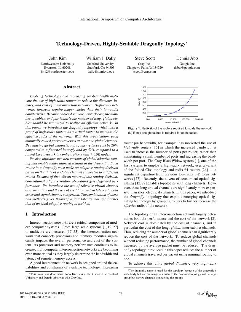
Figure 1. Radix (k) of the routers required to scale the network(N) if only one global hop is required for each packet.
router pin bandwidth, for example, has motivated the use ofhigh-radix routers [15] in which the increased bandwidth isused to increase the number of ports per router, rather thanmaintaining a small number of ports and increasing the band-width per port. The Cray BlackWidow system [1], one of thefirst systems to employ a high-radix network, uses a variantof the folded-Clos topology and radix-64 routers [26] — asignificant departure from previous low-radix 3-D torus net-works [27]. Recently, the advent of economical optical sig-nalling [12, 22] enables topologies with long channels. How-ever, these long optical channels are significantly more expen-sive than short electrical channels. In this paper, we introducethe dragonfly 1 topology that exploits emerging optical sig-naling technology by grouping routers to further increase theeffective radix of the network.
The topology of an interconnection network largely deter-mines both the performance and the cost of the network [8].Network cost is dominated by the cost of channels, and inparticular the cost of the long, global, inter-cabinet channels.Thus, reducing the number of global channels can significantlyreduce the cost of the network. To reduce global channelswithout reducing performance, the number of global channelstraversed by the average packet must be reduced. The drag-onfly topology introduced in this paper reduces the number ofglobal channels traversed per packet using minimal routing toone.
To achieve this unity global diameter, very high-radix
1The dragonfly name is used for the topology because of the dragonfly’swide body but narrow wings – similar to the proposed topology with a largegroup but narrow channels connecting the groups.
International Symposium on Computer Architecture
1063-6897/08 $25.00 © 2008 IEEEDOI 10.1109/ISCA.2008.19
77
International Symposium on Computer Architecture
1063-6897/08 $25.00 © 2008 IEEEDOI 10.1109/ISCA.2008.19
77

cables distance data rate power E/bit Optical TechnologyIntel Connects Cable [12] <100m 20Gb/s 1.2W 60pJ VCSELs, multi-
mode fiberLuxtera Blazar [21] <300m 42Gb/s 2.2W 55pJ CMOS Photonics,
single-mode fiberconventional electrical cable [23] <10m 10Gb/s 20mW 2pJ –
Table 1. Comparison of the different cables and their characteristics. The comparison is shown for 4x cables and the delay/powerconsumption are for the active components of the cable.
routers, with a radix of #2$
N (where N is the size of the net-work) are required. 2 While radix 64 routers have been intro-duced [26], and a radix of 128 is feasible, much higher radicesare needed to build machines that scale to 8K - 1M nodes, asshown in Figure 1. To achieve the benefits of a very high radix,we propose using a group of routers connected into a subnet-work as one very high radix virtual router. This very higheffective radix in turn allows us to build a network in whichall minimal routes traverse at most one global channel. It alsoincreases the physical length of the global channels, exploitingthe capabilities of emerging optical signaling technology.
Achieving good performance on a wide range of traffic pat-terns on a dragonfly topology requires a routing algorithm thatcan effectively balance load across the global channels. Globaladaptive routing (UGAL) [29], can perform such load bal-ancing if the load of the global channels is available at thesource router, where the routing decision is made. With thedragonfly topology, however, the source router is most of-ten not connected to the global channel in question. Hence,the adaptive routing decision must be made based on remoteor indirect information. The indirect nature of this decisionleads to degradation in both latency and throughput when con-ventional UGAL (which uses local queue occupancy to makerouting decisions) is used. We propose two modificationsto the UGAL routing algorithm that overcome this limitationwith performance results approaching an ideal implementationusing global information. Adding selective virtual-channeldiscrimination to UGAL (UGALV C H ) eliminates bandwidthdegradation due to local channel sharing between minimal andnon-minimal paths. Using credit-round trip latency to bothsense global channel congestion and to propagate this con-gestion information upstream (UGALCR) eliminates latencydegradation by providing much stiffer backpressure than ispossible using only queue occupancy for congestion sensing.
The rest of the paper is organized as follows. In Sec-tion 2, we provide background into signaling technology anddevelop a cost model for signaling. The dragonfly topologyis described in detail in Section 3 and the different routing al-gorithms are discussed in Section 4. Section 5 provides ad-ditional discussion on the topology and comparison to othertopologies. Related work is presented in Section 6 and Sec-tion 7 presents our conclusions.
2A fully connected topology with a concentration of!
N is assumed.
y = 0.364x + 9.7103
0
10
20
30
40
50
0 20 40 60 80 100Length (m)
Cos
t ($/
Gb) Intel Connects Cables
electrical cable cost model y = 1.4x + 2.16
Figure 2. Cost model comparison of active optical cables [12]and electrical cables with repeaters [14].
2 Technology Model
High-radix networks reduce the diameter of the networkbut require longer cables compared to low-radix networks. Inthis section, we discuss signaling technology and how the re-cent development of active optical cables enables high-radixtopologies with longer cables. In addition, we present a costmodel for cables that will be used to compare alternativetopologies in Section 5.
An interconnection network is embedded in a packaginghierarchy. At the lowest level, the routers are connected viacircuit boards, which are then connected via a backplane ormidplane. One or more backplanes are packaged in a cabinet,with multiple cabinets connected by electrical or optical cablesto form a complete system. The global (inter-cabinet) cablesand their associated transceivers often dominate the cost of anetwork. To minimize the network cost, the topology shouldbe matched to the characteristics of the available interconnecttechnologies.
The maximum bandwidth of an electrical cable drops withincreasing cable length because signal attenuation due to skineffect and dielectric absorption increases linearly with dis-tance [6].3 For typical high-performance signaling rates (10-20Gb/s) and technology parameters, electrical signaling pathsare limited to about 1m in circuit boards and 10m in cables. Atlonger distances, either the signaling rate must be reduced orrepeaters inserted to overcome attenuation.
Historically, the high cost of optical signaling limited itsuse to very long distances or applications that demanded per-
3Attenuation in circuit boards (including backplanes) is primarily due todielectric absorption while in cables skin effect dominates.
7878

G0 G1
inter-groupinterconnection network
Gg
P0 P1 Pk’-1 PN-k’-1PN-k’ PN-1Pk’ Pk’+1 P2k’-1
Group
gck’-1gc0
R1R0 Ra-1
gch
tc0 tc1 tcp tck’-1tcp-1
gch-1gc1
intra-groupinterconnection network
global channels (gc)
local channels
terminal channels (tc)
(a) (b)
Figure 3. (a) Block diagram of a group (virtual router) and (b) high-level block diagram of a dragonfly topology composed of multiplegroups. gci corresponds to global channels for inter-group connections and tci corresponds to channels connected to the terminals (orprocessors).
formance regardless of cost. Recent advances in silicon pho-tonics and their application to active optical cables such asIntel Connects Cables [12] and Luxtera Blazar [21, 22] haveenabled economical optical interconnect. These active opticalcables have electrical connections at either end and EO andOE 4 modules integrated into the cable itself. The characteris-tics of the active optical cables from Intel and Luxtera as wellas a conventional electrical cables are compared in Table 1.
Figure 2 compares the cost of electrical and optical sig-naling bandwidth as a function of distance. The cost of IntelConnect Cables [12] is compared with the electrical cable costmodel presented in [14]. 5 Optical cables have a higher fixedcost (y-intercept) but a lower cost per unit distance (slope)than electrical cables. Based on the data presented here, thecrossover point is at 10m. For distances shorter than 10m, elec-trical signaling is less expensive. Beyond 10m, optical signal-ing is more economical. The topology proposed in this paperexploits this relationship between cost and distance. By reduc-ing the number of global cables it minimizes the effect of thehigher fixed overhead of optical signaling, and by making theglobal cables longer, it maximizes the advantage of the lowerper-unit cost of optical fibers.
3 Dragonfly Topology
The following symbols are used in our description of thedragonfly topology in this section and the routing algorithmsin Section 4.
N Number of network terminalsp Number of terminals connected to each routera Number of routers in each groupk Radix of the routersk! Effective radix of the group (or the virtual router)
4EO : Electrical to Optical, OE : Optical to Electrical5The optical cost is based on prices available at http://shop.intel.com. If
purchased in bulk, the prices will likely be lower. The use of single-modefiber instead of multi-mode fiber may also result in lower cost.
h Number of channels within each router used to con-nect to other groups
g Number of groups in the systemq Queue depth of an output port
qvc Queue depth of an individual output VCH Hop count
Outi Router output port i
3.1 Topology Description
The dragonfly is a hierarchical network with three levels:router, group, and system as shown in Figure 3. At the bottomlevel, each router has connections to p terminals, a % 1 localchannels — to other routers in the same group — and h globalchannels — to routers in other groups. Hence the radix (or de-gree) of each router is k = p + a + h % 1. A group consistsof a routers connected via an intra-group interconnection net-work formed from local channels (Figure 3(a)). Each grouphas ap connections to terminals and ah connections to globalchannels, and all of the routers in a group collectively act as avirtual router with radix k! = a(p + h). This very high radix,k! >> k enables the system level network (Figure 3(b)) to berealized with very low global diameter (the maximum numberof expensive global channels on the minimum path betweenany two nodes). Up to g = ah + 1 groups (N = ap(ah + 1)terminals) can be connected with a global diameter of one.In contrast, a system-level network built directly with radixk routers would require a larger global diameter.
In a maximum-size (N = ap(ah + 1)) dragonfly, thereis exactly one connection between each pair of groups. Insmaller dragonflies, there are more global connections out ofeach group than there are other groups. These excess globalconnections are distributed over the groups with each pair ofgroups connected by at least &ah+1
g ' channels.The dragonfly parameters a, p, and h can have any values.
However to balance channel load on load-balanced traffic, thenetwork should have a = 2p = 2h. Because each packettraverses two local channels along its route (one at each end
7979
1
10
100
1,000
10,000
100,000
1,000,000
0 20 40 60 80Router radix (k)
Net
wor
k si
ze (N
)
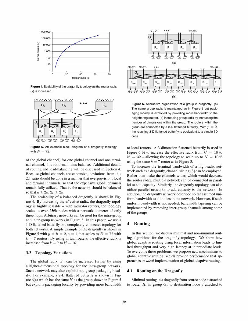
Figure 4. Scalability of the dragonfly topology as the router radix(k) is increased.
P0 P1 P2 P3 P4 P5 P6 P7
R0 R1 R2 R3
G0
G1 G8G2
Figure 5. An example block diagram of a dragonfly topologywith N = 72.
of the global channel) for one global channel and one termi-nal channel, this ratio maintains balance. Additional detailsof routing and load-balancing will be discussed in Section 4.Because global channels are expensive, deviations from this2:1 ratio should be done in a manner that overprovisions localand terminal channels, so that the expensive global channelsremain fully utilized. That is, the network should be balancedso that a " 2h, 2p " 2h.
The scalability of a balanced dragonfly is shown in Fig-ure 4. By increasing the effective radix, the dragonfly topol-ogy is highly scalable – with radix-64 routers, the topologyscales to over 256k nodes with a network diameter of onlythree hops. Arbitrary networks can be used for the intra-groupand inter-group networks in Figure 3. In this paper, we use a1-D flattened butterfly or a completely-connected topology forboth networks. A simple example of the dragonfly is shown inFigure 5 with p = h = 2, a = 4 that scales to N = 72 withk = 7 routers. By using virtual routers, the effective radix isincreased from k = 7 to k! = 16.
3.2 Topology Variations
The global radix, k!, can be increased further by usinga higher-dimensional topology for the intra-group network.Such a network may also exploit intra-group packaging local-ity. For example, a 2-D flattened butterfly is shown in Fig-ure 6(a) which has the same k! as the group shown in Figure 5but exploits packaging locality by providing more bandwidth
P0 P1 P2 P3 P4 P5 P6 P7
R0 R1 R2 R3
22
G0
gc0 gc1 gc6 gc7
(a)
P8 P9 P10 P11 P12 P13 P14 P15
R100 R101 R110 R111
P0 P1 P2 P3 P4 P5 P6 P7
R000 R001 R010 R011
G0
gc0 gc1 gc2 gc3 gc14 gc15
(b)
Figure 6. Alternative organization of a group in dragonfly. (a)The same group radix is maintained as in Figure 5 but pack-aging locality is exploited by providing more bandwidth to theneighboring routers. (b) Increasing group radix by increasing thenumber of dimensions within the group. The routers within thegroup are connected by a 3-D flattened butterfly. With p = 2,the resulting 3-D flattened butterfly is equivalent to a simple 3Dcube.
to local routers. A 3-dimension flattened butterfly is used inFigure 6(b) to increase the effective radix from k! = 16 tok! = 32 – allowing the topology to scale up to N = 1056using the same k = 7 router as in Figure 3.
To increase the terminal bandwidth of a high-radix net-work such as a dragonfly, channel slicing [8] can be employed.Rather than make the channels wider, which would decreasethe router radix, multiple network can be connected in paral-lel to add capacity. Similarly, the dragonfly topology can alsoutilize parallel networks to add capacity to the network. Inaddition, the dragonfly network described so far assumed uni-form bandwidth to all nodes in the network. However, if suchuniform bandwidth is not needed, bandwidth tapering can beimplemented by removing inter-group channels among someof the groups.
4 Routing
In this section, we discuss minimal and non-minimal rout-ing algorithms for the dragonfly topology. We show howglobal adaptive routing using local information leads to lim-ited throughput and very high latency at intermediate loads.To overcome these problems, we propose new mechanisms toglobal adaptive routing, which provide performance that ap-proaches an ideal implementation of global adaptive routing.
4.1 Routing on the Dragonfly
Minimal routing in a dragonfly from source node s attachedto router Rs in group Gs to destination node d attached to
8080

Rx Ry
VC1
Rs Ra
VC0
Rb Rd
VC2
VC0VC1
VC1
VC1 VC2
Gs
Gi
Gd
minimal routenon-minimal route
Figure 7. Virtual channel assignment to prevent routing dead-lock in a dragonfly topology with both minimal and nonminimalrouting.
router Rd in group Gd traverses a single global channel and isaccomplished in three steps:
Step 1 : If Gs (= Gd and Rs does not have a connection toGd, route within Gs from Rs to Ra, a router that has a globalchannel to Gd.
Step 2 : If Gs (= Gd, traverse the global channel from Ra
to reach router Rb in Gd.Step 3 : If Rb (= Rd, route within Gd from Rb to Rd.
This minimal routing works well for load-balanced traffic, butresults in very poor performance on adversarial traffic patterns.
To load-balance adversarial traffic patterns, Valiant’s algo-rithm [32] can be applied at the system level — routing eachpacket first to a randomly-selected intermediate group Gi andthen to its final destination d. Applying Valiant’s algorithm togroups suffices to balance load on both the global and localchannels. This randomized non-minimal routing traverses atmost two global channels and requires five steps:
Step 1 : If Gs (= Gi and Rs does not have a connection toGi, route within Gs from Rs to Ra, a router that has a globalchannel to Gi.
Step 2 : If Gs (= Gi traverse the global channel from Ra toreach router Rx in Gi.
Step 3 : If Gi (= Gd and Rx does not have a connection toGd, route within Gi from Rx to Ry , a router that has a globalchannel to Gd.
Step 4 : If Gi (= Gd, traverse the global channel from Ry
to router Rb in Gd.Step 5 : If Rb (= Rd, route within Gd from Rb to Rd.
Figure 7 shows how virtual channels (VCs) [5] are usedto avoid routing deadlock. To prevent routing deadlock [7],two VCs are needed for minimal routing and three VCs arerequired for non-minimal routing. This assignment eliminatesall channel dependencies due to routing. For some applica-tions, additional virtual channels may be required to avoid pro-tocol deadlock — e.g., for shared memory systems, separatesets of virtual channels are required for request and reply mes-sages.
4.2 Evaluation
We evaluate the following routing algorithms for the drag-onfly topology.
Minimal (MIN) : The minimal path is taken as described inSection 4.1.
Valiant (VAL) [32] : Randomized non-minimal routing asdescribed in Section 4.1.
Universal Globally-Adaptive Load-balanced [29] (UGAL-G, UGAL-L) UGAL chooses between MIN and VAL on apacket-by-packet basis to load-balance the network. Thechoice is made by using queue length and hop count to es-timate network delay and choosing the path with minimumdelay. We implement two versions of UGAL.
UGAL-L – uses local queue information at the currentrouter node.
UGAL-G – uses queue information for all the global chan-nels in Gs — assuming knowledge of queue lengths on otherrouters. While difficult to implement, this represents an idealimplementation of UGAL since the load-balancing is requiredof the global channels, not the local channels.
Cycle accurate simulations are used to evaluate the per-formance of the different routing algorithms. We simulatea single-cycle, input-queued router switch but provide suffi-cient speedup in order to generalize the results and ensurethat routers do not become the bottleneck of the network.Packets are injected using a Bernoulli process. The simula-tor is warmed up under load without taking measurements un-til steady-state is reached. Then a sample of injected packetsis labeled during a measurement interval. The simulation isrun until all labeled packets exit the system. Unless otherwisenoted, the simulation results are shown for dragonfly of size1K node using p = h = 4 and a = 8 parameters. Simu-lations of other size networks follow the same trend and arenot presented due to space constraints. Single flit (flow controlunit) packets are used to separate the routing algorithm fromflow control issues such as the use of wormhole or virtual cut-through flow control. 6 The input buffers are initially assumedto be 16 flits deep. The impact of different buffer sizes is alsoevaluated.
The different routing algorithms are evaluated using bothbenign and adversarial synthetic traffic patterns. The use ofsynthetic traffic pattern allows us to stress the topology androuting algorithm to fully evaluate the network. For benigntraffic such as uniform random (UR), MIN is sufficient toprovide low latency and high throughput (Figure 8(a)). VALachieves approximately half of the network capacity becauseits load-balancing doubles the load on the global channels.Both UGAL-G and UGAL-L approach the throughput of MIN,but with slightly higher latency near saturation. The higherlatency is caused by the use of parallel or greedy allocationwhere the routing decision at each port is made in parallel.
6Simulations show that larger packets with sufficient buffering to providevirtual cut-through do not change the result trends presented in the paper.
8181

0
5
10
15
20
25
30
0 0.2 0.4 0.6 0.8 1
Offered load
La
ten
cy (
cycle
s)
VAL UGAL-L UGAL-G MIN
0
5
10
15
20
25
30
0 0.1 0.2 0.3 0.4 0.5 0.6
Offered LoadL
ate
ncy (
cycle
s)
MIN UGAL-L VAL UGAL-G
(a) (b)
Figure 8. Routing algorithm comparison on the dragonfly for (a)uniform random traffic and (b) adversarial traffic pattern.
The use of sequential allocation [13] will reduce the latency atthe expense of a more complex allocator.
To test the load-balancing ability of a routing algorithm, weuse a worst-case (WC) traffic pattern where each node in groupGi sends traffic to a randomly selected node in group Gi+1.With minimal routing, this pattern will cause all nodes in eachgroup Gi to send all of their traffic across the single globalchannel to group Gi+1. Non-minimal routing is required toload balance this traffic pattern by spreading the bulk of thetraffic across the other global channels.
The evaluation for this WC traffic is shown in Figure 8(b).Because MIN forwards all of the traffic from each group acrossa single channel, its throughput is limited to 1
ah . VAL achievesslightly under 50% throughput which is the maximum pos-sible throughput with this traffic. 7 UGAL-G achieves sim-ilar throughput as VAL but UGAL-L leads to both limitedthroughput as well as high average packet latency at interme-diate load. In the following section, we show how the indirectnature of adaptive routing on the dragonfly leads to perfor-mance degradation. We identify the issues with UGAL-L andpresent mechanisms that can overcome these problems.
4.3 Indirect Adaptive Routing
Adaptive routing on the dragonfly is challenging because itis the global channels, the group outputs, that need to be bal-anced, not the router outputs. This leads to an indirect routingproblem. Each router must pick a global channel to use us-ing only local information that depends only indirectly on thestate of the global channels. Previous global adaptive rout-ing methods [3, 29, 30] used local queue information, sourcequeues and output queues, to generate accurate estimates ofnetwork congestion. In these cases, the local queues were anaccurate proxy of global congestion, because they directly in-dicated congestion on the routes they initiated. With the drag-onfly topology, however, local queues only sense congestionon a global channel via backpressure over the local channels.If the local channels are overprovisioned, significant numbers
7If additional buffering is provided, the theoretically expect throughput of50% is achieved.
0
0.2
0.4
0.6
0.8
1
Global channels
Cha
nnel
util
izat
ion
UGAL-GUGAL-L
minimal globalchannel
channels within same router
Figure 9. Global channel utilization for the dragonfly topologywith UGAL-L and UGAL-G routing using the adversarial trafficpattern. The data is collected from an offered load of 0.2, justprior to the saturation of UGAL-L.
of packets must be enqueued on the overloaded minimal routebefore the source router will sense the congestion. This resultsin a degradation in throughput and latency as shown earlier inFigure 8(b).
4.3.1 Problem I: Limited throughput
The throughput issue with UGAL-L is due to a single localchannel handling both minimal and non-minimal traffic. Forexample, in Figure 13, a packet in R1 has a minimal pathwhich uses gc7 and a nonminimal path which uses gc6. Bothpaths share the same local channel from R1 to R2. Becauseboth paths share the same local queue (and hence have thesame queue occupancy) and the minimal path is shorter (oneglobal hop vs two), the minimal channel will always be se-lected, even when it is saturated. This leads to the minimalglobal channel being overloaded and the non-minimal globalchannels that share the same router as the minimal channel be-ing under utilized. This effect is shown in Figure 9. The firstglobal channel is the minimal global channel, the next threeglobal channels are non-minimal channels that share the samerouter with the minimal channels (h = 4), and the remainingchannels are non-minimal channels that share the same group.With UGAL-G, the minimal channel is preferred and the loadis uniformly balanced across all other global channels. WithUGAL-L, on the other hand, the non-minimal channels on therouter that contains the minimal global channel are under uti-lized – resulting in a degradation of network throughput.
To overcome this limitation, we modify the UGAL algo-rithm 8 to separate the queue occupancy into minimal and non-minimal components by using individual VCs (UGAL-LV C ).
if (qm vcHm ) qnm vcHnm )
route minimally;else
route nonminimally;
8The original UGAL routing algorithm can be described as – if (qmHm "qnmHnm) route minimally; else route nonminimally; [29].
8282

0
5
10
15
20
25
30
35
40
0 0.2 0.4 0.6 0.8 1Offered load
La
tency (
cycle
s)
UGAL-L (vc) UGAL-L (vc-h) UGAL-L UGAL-G
0
5
10
15
20
25
30
0 0.1 0.2 0.3 0.4 0.5 0.6Offered load
La
tency (
cycle
s)
UGAL-L UGAL-L (vc-h) UGAL-L (vc) UGAL-G
(a) (b)
Figure 10. Evaluation of alternative UGAL-L implementation for(a) uniform random traffic and (b) worst-case traffic.
where the subscript m and nm denote the minimal and non-minimal paths. If the VC assignment of Figure 7 is used,qm vc = q(V C1) and qnm vc = q(V C0).
The modified routing algorithm (UGAL-LV C) is comparedfor both WC and UR traffic in Figure 10. UGAL-LV C matchesthe throughput of UGAL-G on WC traffic pattern but for URtraffic, the throughput is limited, with approximately 30% re-duction in throughput (Figure 10(a)). For the WC traffic wheremost of the traffic needs to be sent non-minimally, UGAL-LV C performs well since the minimal queue is heavily loaded.However, for load-balanced traffic when most traffic should besent minimally, individual VCs do not provide an accurate rep-resentation of the channel congestion – resulting in throughputdegradation.
To overcome this limitation, we further modify the UGALalgorithm to separate the queue occupancy into minimal andnon-minimal components only when the minimal and non-minimal paths start with the same output port. Our hybridmodified UGAL routing algorithm (UGAL-LV C H ) is
if (qmHm ) qnmHnm && Outm (= Outnm ) ||(qm vcHm ) qnm vcHnm && Outm = Outnm )
route minimally;else
route nonminimally;
Compared to UGAL-LV C , UGAL-LV C H provides the samethroughput on WC traffic pattern but matches the throughputof UGAL-G on UR traffic but resulting in nearly 2* higherlatency at an offered load of 0.8, near saturation. For WC traf-fic, UGAL-LV C H also results in higher intermediate latencycompared to UGAL-G (Figure 10(b)). In the next section, wediscuss the issue of higher intermediate latency and a mech-anism to provide stiffer backpressure to reduce intermediatelatency.
4.3.2 Problem II: Higher intermediate latency
The high intermediate latency of UGAL-L is due tominimally-routed packets having to fill the channel buffers be-tween the source and the point of congestion before conges-
0
20
40
60
80
100
0 0.1 0.2 0.3 0.4 0.5 0.6Offered load
La
ten
cy (
cycle
s)
minimal pkts average non-minimal pkts
buffersize
0
50
100
150
200
250
300
350
400
0 0.1 0.2 0.3 0.4 0.5 0.6Offered load
La
ten
cy (
cycle
s)
minimal pkts average non-minimal pkts
(a) (b)
Figure 11. Latency vs. offered load for the dragonfly topologywith UGAL-L routing and adversarial traffic pattern with the inputbuffers of depth (a) 16 and (b) 256.
0
0.05
0.1
0.15
0.2
0.25
0.3
0 10 20 30 40 50 60
Latency
% o
f p
acke
tsavg latency = 19.2
minimally routed packets
0
0.05
0.1
0.15
0.2
0.25
0.3
0 50 100 150 200 250 300 350Latency (cycles)
% o
f p
acke
ts
avg latency = 39.19
minimally routed packets
(a) (b)
Figure 12. Histogram distribution of average packet latency atan offered load of 0.25 in the dragonfly topology with UGAL-Lrouting adversarial traffic pattern and the input buffers of depth(a) 16 and (b) 256.
tion is sensed. In Figure 11, we plot the latency of minimally-routed and non-minimally-routed packets as well as the overallaverage latency.9 The figure shows that non-minimally routedpackets have a latency curve comparable to UGAL-G whileminimally-routed packets see significantly higher latency. Fig-ure 11(b) shows that as input buffers are increased, the latencyof minimally-routed packets increases and is proportional tothe depth of the buffers. A histogram of latency distribution(Figure 12) shows two clear distributions – one large distribu-tion with low latency for the non-minimal packets and anotherdistribution with a limited number of packets but with muchhigher latency for the minimal packets.
To understand this problem with UGAL-L, in the exam-ple dragonfly group shown in Figure 13, assume a packet inR1 is making its global adaptive routing decision of routingeither minimally through gc0 or non-minimally through gc7.The routing decision needs to load balance global channel uti-lization and ideally, the channel utilization can be obtainedfrom the queues associated with the global channels, q0 andq3. However, q0 and q3 queue informations are only avail-able at R0 and R2 and not readily available at R1 – thus, the
9The average latency is the weighted average between minimal and non-minimal packets.
8383

Group
R1R0
tc0 tc1 tc2 tc3 tc4 tc5
R2
tc6 tc7 tc8
gc0gc2gc1 gc3 gc5gc4 gc6 gc8gc7
q0
q1 q2
q3
Figure 13. A block diagram of a dragonfly topology to illustrateindirect adaptive routing.
routing decision can only be made indirectly through the lo-cal queue information available at R1. In this example, q1
reflects the state of q0 and q2 reflects the state of q3. Wheneither q0 or q3 is full, the flow control provides backpressureto q1 and q2 as shown with the arrows in Figure 13. As a re-sult, in steady-state measurement, these local queue informa-tion can be used to accurately measure the throughput. Sincethe throughput is defined as the offered load when the latencygoes to infinity (or the queue occupancy goes to infinity) [8],this local queue information is sufficient. However, q0 needsto be completely full in order for q1 to reflect the congestion ofgc0 and allow R1 to route packets non-minimally. Thus, usinglocal information requires sacrificing some packets to prop-erly determine the congestion – resulting in packets being sentminimally having much higher latency. As the load increases,although minimally routed packets continue to increase in la-tency, more packets are sent non-minimally and results in adecrease in average latency until saturation.
In order for local queues to provide a good estimate ofglobal congestion, the global queues need to be completelyfull and provide a stiff backpressure towards the local queues.The stiffness of the backpressure is inversely proportional tothe depth of the buffer – with deeper buffers, it takes longer forthe backpressure to propagate while with shallower buffers, amuch stiffer backpressure is provided. Simulation results asthe buffer size is varied are shown in Figure 14. As the buffersize decreases, the latency at intermediate load is decreasedbecause of the stiffer backpressure. However, using smallerbuffers comes at the cost of reduced network throughput. 10
To overcome the high intermediate latency, we propose us-ing credit round-trip latency to sense congestion faster andreduce latency. In credit-based flow control (Figure 17(a)),credit counts are maintained for buffers downstream. As pack-ets are sent downstream, the appropriate credit count is decre-mented and once the packet leaves downstream router, creditsare sent back upstream and the credit count is incremented.The latency for the credits to return is referred to as creditround-trip latency (tcrt) and a timeline of zero-load credit
10The input buffers are usually large to support virtual cut-through flowcontrol for the maximum size packet. For example, YARC router input bufferhas 256 flit entries [26].
0
5
10
15
20
25
30
0 0.1 0.2 0.3 0.4 0.5 0.6Offered load
Late
ncy
(cyc
les)
4 8 16 32 64
Figure 14. Latency vs. offered load for the dragonfly topologyas the amount of input buffers are varied.
time
R0 R1 R2
tcrt0
flit
proc
ess
flitcredit
proc
ess
flitcredit
R0 R1 R2
tcrt
flit
proc
ess
flitcredit
proc
ess
contention
(a) (b)
Figure 15. Credit round-trip latency timeline (a) when there is nocongestion in the network (tcrt0) and (b) when channel betweenR1 and R2 is congested (tcrt).
round-trip latency (tcrt0) is shown in Figure 15(a). If thereis congestion downstream, the packet cannot be immediatelyprocessed and results in an increase in tcrt as shown in Fig-ure 15(b).
The value of tcrt can be used to estimate the congestion ofglobal channels. By using this information to delay upstreamcredits, we stiffen the backpressure and more rapidly propa-gate congestion information up stream. For each output O,tcrt(O) is measured and the quantity td(O) = tcrt(O) % tcrt0
is stored in a register. Then, when a flit is sent to output O, in-stead of immediately sending a credit back upstream, the creditis delayed by td(O) % min [td(o)]. The credits sent across theglobal channels are not delayed. This ensures that there is nocyclic loop in this mechanism and allows the global channelsto be fully utilized.
The delay of returning credits provides the appearance ofshallower buffers to create a stiff backpressure. However, toensure that the entire buffer gets utilized and there is no re-duced throughput at high load, the credits needs to delayed bythe variance of td across all outputs. We estimate the varianceby finding min [td(o)] value and using the difference. By de-laying credits, the upstream routers observes congestion at afaster rate (compared to waiting for the queues to fill up) andleads to better global adaptive routing decisions.
The UGAL-L routing algorithm evaluation using credit la-tency (UGAL-LCR) 11 is shown in Figure 16 for both WC and
11The UGAL-LCR is implemented on top of UGAL-LV C H .
8484
0
5
10
15
20
25
30
0 0.1 0.2 0.3 0.4 0.5 0.6Offered load
La
ten
cy (
cycle
s)
UGAL-L (vc-h) UGAL-L(cr) UGAL-G
0
20
40
60
80
100
0 0.1 0.2 0.3 0.4 0.5 0.6Offered load
La
ten
cy (
cycle
s)
UGAL-L (vc-h) UGAL-L(cr) UGAL-G
(a) (b)
0
10
20
30
40
0.5 0.6 0.7 0.8 0.9 1Offered load
La
ten
cy (
cycle
s)
UGAL-L (vc-h) UGAL-L(cr) UGAL-G
0
5
10
15
20
25
30
35
40
0.4 0.5 0.6 0.7 0.8 0.9 1Offered load
La
ten
cy (
cycle
s)
UGAL-L (vc-h) UGAL-L(cr) UGAL-G
(c) (d)
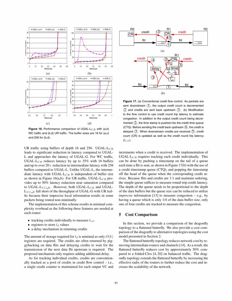
Figure 16. Performance comparison of UGAL-LCR with (a,b)WC traffic and (b,d) UR traffic. The buffer sizes are 16 for (a,c)and 256 for (b,d).
UR traffic using buffers of depth 16 and 256. UGAL-LCR
leads to significant reduction in latency compared to UGAL-L and approaches the latency of UGAL-G. For WC traffic,UGAL-LCR reduces latency by up to 35% with 16 buffersand up to over 20* reduction in intermediate latency with 256buffers compared to UGAL-L. Unlike UGAL-L, the interme-diate latency with UGAL-LCR is independent of buffer sizeas shown in Figure 16(a,b). For UR traffic, UGAL-LCR pro-vides up to 50% latency reduction near saturation comparedto UGAL-LV C H . However, both UGAL-LCR and UGAL-LV C H fall short of the throughput of UGAL-G with UR traf-fic because their imprecise local information results in somepackets being routed non-minimally.
The implementation of this scheme results in minimal com-plexity overhead as the following three features are needed ateach router:
• tracking credits individually to measure tcrt
• registers to store td values• a delay mechanism in returning credits
The amount of storage required for td is minimal as only O(k)registers are required. The credits are often returned by pig-gybacking on data flits and delaying credits to wait for thetransmission of the next data flit upstream is required. Theproposed mechanism only requires adding additional delay.
As for tracking individual credits, credits are convention-ally tracked as a pool of credits in credit flow control – i.e.,a single credit counter is maintained for each output VC and
flit
creditCR
flit
creditCR2
1
3R0 R1 R2
(a)
CTQCR
delay
tcrt
flit
credit
flit
credit
time
R1
3
1
245
(b)
Figure 17. (a) Conventional credit flow control. As packets aresent downstream 1+, the output credit count is decremented2+ and credits are sent back upstream 3+. (b) Modification
to the flow control to use credit round trip latency to estimatecongestion. In addition to the output credit count being decre-mented 2+, the time stamp is pushed into the credit time queue(CTQ). Before sending the credit back upstream 4+, the credit isdelayed 3+. When downstream credits are received 5+, creditcount (CR) is updated as well as the credit round trip latency(tcrt).
increments when a credit is received. The implementation ofUGAL-LCR requires tracking each credit individually. Thiscan be done by pushing a timestamp on the tail of a queueeach time a flit is sent, as shown in Figure 17(b) with the use ofa credit timestamp queue (CTQ), and popping the timestampoff the head of the queue when the corresponding credit ar-rives. Because flits and credits are 1:1 and maintain ordering,the simple queue suffices to measure round-trip credit latency.The depth of the queue needs to be proportional to the depthof the data buffers but the queue size can be reduced to utilizeimprecise information [13] to measure congestion – e.g., byhaving a queue which is only 1/4 of the data buffer size, onlyone of four credits are tracked to measure the congestion.
5 Cost Comparison
In this section, we provide a comparison of the dragonflytopology to a flattened butterfly. We also provide a cost com-parison of the dragonfly to alternative topologies using the costmodel presented in Section 2.
The flattened butterfly topology reduces network cost by re-moving intermediate routers and channels [14]. As a result, theflattened butterfly reduces cost by approximately 50% com-pared to a folded-Clos [4, 20] on balanced traffic. The drag-onfly topology extends the flattened butterfly by increasing theeffective radix of the routers to further reduce the cost and in-crease the scalability of the network.
8585

16
16
16
16
P0 P1 P15
R1
P16 P17 P31
R15
P240 P241 P255
R0
1515
1515
1515
(a)
1 1
1
1
P0 P1 P15
R1
P16 P17 P31
R15
P240 P241 P255
R0
16 16 16
22
2
(b)
15
1515
dimension 1channels
dimension 2 channelsdimension 3channels
router
P0 P1 P15
16
1515
intra-groupchannels
inter-groupchannels
router
P0 P1 P15
Flattened Butterfly Dragonfly
global cableslocal cables
(c)
Figure 18. Topology comparison of a 64K network for (a) 3-Dflattened butterfly and (b) dragonfly. The squares represents asmall number of cabinets required to connect the 256 nodes andthe global channels are only shown for lower-left corner group.The routers used in the topologies are compared in (c).
A comparison of dragonfly and flattened butterfly networksof 64K nodes is shown in Figure 18(a,b). The group size ofthe dragonfly is 16 routers (256 terminals) and this is also thesize of each dimension of the flattened butterfly. To scale to64K nodes, the flattened butterfly requires two additional di-mensions, each of size 16, while the dragonfly, with its ef-fective radix of 256, connects all of the groups in a single,large dimension. Thus, while both topologies provide the sameamount of global bisection bandwidth, the dragonfly requiresonly half the number of global cables compared to the flat-tened butterfly. As shown in Figure 18(c)), the flattened but-terfly uses 50% of the router ports for global channels whilethe dragonfly uses only 25% of the ports for global channels.In addition, the dragonfly provides better scalability becausethe group size can be increased to scale the network whereasscaling the flattened butterfly requires adding additional di-mensions. The two topology comparisons are summarized inTable 2. With the hop count nearly identical, the dragonflytrades off longer global cables for smaller number of globalcables required to provide a more cost-efficient topology bet-ter matched to emerging signaling technologies.
Figure 19 compares the cost of the dragonfly, flattened but-
terfly, Clos, and 3D-torus networks as a function of the numberof terminal nodes. For short cables (<8m) we use the electri-cal cable cost model (from [14]). For cables longer than 8mwe use the active optical cable cost model (Section 2). We as-sume the use of radix-64 routers for the high-radix networksand adjust the cost of the router appropriately for the low-radix3-D torus network. For the dragonfly network we use a groupsize of 512 nodes.
Folded-Clos
Flattened Butterfly
Dragonfly
3-D Torus
$0
$40
$80
$120
$160
$200
0 5000 10000 15000 20000Network size (N)
Cos
t ($)
per
nod
eFigure 19. Cost comparison of the dragonfly topology to alter-native topologies.
For networks up to 1K nodes, all routers are fully connectedand the dragonfly is identical to a 1-D flattened butterfly – thus,the cost of the two networks are identical. For a topology thatis fully connected, there is no cost benefit of attempting to us-ing virtual routers as it will only increase the cost. For largernetworks, the dragonfly is more scalable not only because ithas higher effective radix but the group size is twice as largeas the dimension size for the flattened butterfly which leads tolower cost. For networks up to 4K nodes, the dragonfly pro-vides approximately 10% savings. This is because the drag-onfly has a shorter average cable length than the flattened but-terfly at these small sizes. For larger networks (>4K nodes),the dragonfly provides approximately 20% cost savings overa flattened butterfly since the dragonfly has fewer long, globalcables.
The 3-D torus network results in short cables and does notrequire the use of optical signalling. However, as shown inFigure 19, the cost of the network is significantly higher thanthe other topologies because of the larger number of cablesneeded to support the high network diameter. For a networkof size 1K, the dragonfly reduces cost by approximately 62%while at a network of size 8K, the dragonfly provides a costsavings of only 47% as the dragonfly topology requires theuse of the more expensive optical cables. However, as thenetwork size increases, the cost benefits of dragonfly exceeds60%. Compared to the folded-Clos, the dragonfly providesover 50% cost savings. The reduction of network cost in thedragonfly also translates to reduction of power as shown inprior work [14].
8686

topology diameter cable lengthminimal nonminimal avg max
flattened butterfly hl + 2hg 2hl + 4hg E/3 Edragonfly 2hl + hg 3hl + 2hg 2E/3 2E†
Table 2. Topology comparison of the dragonfly and the flattened butterfly topology. hl is a local hop, hg is a global hop and E correspondsto the length of a dimension of the system layout. †The maximum length cable for dragonfly can be reduced to
$2E if cables are
connected diagonally.
6 Related Work
Many topologies have been previously proposed and wecompare the dragonfly to some relevant topologies in this sec-tion. The Scalable Opto-Electronic Network (SOENet) [11]was proposed to exploit emerging optical technology. SOENetis constructed by forming subnetworks and connecting multi-ple subnetworks through global switches. The proposed drag-onfly topology shares a similar goal of exploiting optical tech-nology and the structure of creating subnetworks, or groups.However, the dragonfly topology extends the previous workby exploiting high-radix routers and packaging locality to cre-ate very high-radix virtual routers from groups of routers. Inaddition, the dragonfly topology is flat in hierarchy comparedto SOENet since there are no intermediate routers. UnlikeSOENet, in the dragonfly topology all routers are directly con-nected to end terminals, resulting in a reduced network diam-eter and network cost.
Many hierarchical topologies have been previously pro-posed [9, 18, 19]. The dragonfly topology, with an intra- andan inter-group network, can also be referred to as a hierarchi-cal topology. However, the dragonfly topology is fundamen-tally different from previously proposed hierarchical networksin that the radix of the network is increased, thereby provid-ing more global bandwidth, while also reducing network di-ameter. Previously proposed hierarchical networks have beenbuilt as tree-structures. This approach introduces a bandwidthbottleneck and increases hop count and latency as the packetstraverse up the hierarchy. Other product-form networks, suchas the cube-connected cycles [25], have also been proposed,but these networks do not exploit the benefits of increasing theeffective radix of the networks.
The significance of signalling technology for optimal topol-ogy choice was demonstrated through a topology optimizationtool [10]. The availability of economical optical signaling, asdescribed in Section 2, significantly changes the cost modeland enables a topology such as the dragonfly with longer chan-nels. Optical interconnects have the potential to replace elec-trical interconnects due to their higher bandwidth and lowerlatency [24]. To exploit optical technology, complete opticalnetworks have been proposed [2,16,28]. However, because ofthe difficulty of buffering, it becomes very costly to implementa purely optical network. In addition, many optical networksutilize very low-radix networks to simplify the switch and cannot exploit the benefits of high-radix routers. The RAPID
architecture (Reconfigurable and scalable All-Photonic Inter-connect for Distributed-shared memory) [16] is a hierarchicaloptical network that uses passive components. RAPID net-works require longer latency to communicate between differ-ent clusters, and the use of passive network limits the scalabil-ity of the topology.
Routing has been well studied on a k-ary n-cube network.On such networks, when an adaptive routing decision is madebased on the injection queues, Singh [29] showed that althoughoptimal throughput is achieved, the routing algorithm resultsin high latency at intermediate loads. This is similar to whatwas observed in Section 4.3.2. To overcome this, Singh pro-posed the use of channel queues to make adaptive routing deci-sions [31]. However, the indirect nature of the dragonfly topol-ogy prevents the use of channel queues to reduce latency. Theapproach taken in this work demonstrates how to make adap-tive decisions using credit round-trip latency to provide a fastermechanism for sensing congestion and reducing latency.
7 Conclusion
This paper has introduced the dragonfly topology whichuses a group of routers as a virtual router to increase the effec-tive radix of the network, and hence reduce network diameter,cost, and latency. Because it reduces the number global cablesin a network, while at the same time increasing their length,the dragonfly topology is particularly well suited for imple-mentations using emerging active optical cables — which havea high fixed cost but a low cost per unit length compared toelectrical cables. Using active optical cables for the globalchannels, a dragonfly network reduces cost by 20% comparedto a flattened butterfly and by 52% compared to a folded Closnetwork of the same bandwidth.
This paper has also introduced two new variants of globaladaptive routing that overcome the challenge of indirect adap-tive routing presented by the dragonfly. A dragonfly routermust make a routing decision based on the state of a globalchannel attached to a different router in the same group. Con-ventional global adaptive routing algorithms that use localqueue occupancies to infer the state of this remote channelgive degraded throughput and latency. We introduce the se-lective use of virtual channel discrimination to overcome thebandwidth degradation. We also introduce the use of creditround-trip latency to both sense and signal channel conges-tion. The combination of these two techniques gives a global
8787
adaptive routing algorithm that approaches the performance ofan ideal algorithm with perfect knowledge of remote channelstate.
Acknowledgments
The authors would like to thank the anonymous review-ers for their insightful comments and David Black-Schafferfor his feedback on the paper. This work has been supportedin part by the National Science Foundation under ContractCCF0702341, in part by Cray, and in part by the Semiconduc-tor Research Corporation under Contract SRC2007-HJ-1591.References
[1] D. Abts, A. Bataineh, S. Scott, G. Faanes, J. Schwarzmeier, E. Lund-berg, T. Johnson, M. Bye, and G. Schwoerer. The Cray BlackWidow:A Highly Scalable Vector Multiprocessor. In Proceedings of the In-ternational Conference for High Performance Computing, Networking,Storage, and Analysis (SC’07), Reno, NV, Nov. 2007.
[2] R. D. Chamberlain, M. A. Franklin, and C. S. Baw. Gemini: An OpticalInterconnection Network for Parallel Processing. IEEE Transactions onParallel and Distributed Systems, 13(10):1038–1055, 2002.
[3] D. Chiou, L. R. Dennison, and W. J. Dally. Adaptive source routingand packet processing. United States Patent 20050100035, May 2005.
[4] C. Clos. A Study of Non-Blocking Switching Networks. The BellSystem technical Journal, 32(2):406–424, March 1953.
[5] W. J. Dally. Virtual-channel Flow Control. IEEE Transactions on Par-allel and Distributed Systems, 3(2):194–205, 1992.
[6] W. J. Dally and J. W. Poulton. Digital systems engineering. CambridgeUniversity Press, New York, NY, 1998.
[7] W. J. Dally and C. L. Seitz. Deadlock-free message routing in multi-processor interconnection networks. IEEE Transactions on Computers,36(5):547–553, 1987.
[8] W. J. Dally and B. Towles. Principles and Practices of InterconnectionNetworks. Morgan Kaufmann, San Francisco, CA, 2004.
[9] S. Dandamudi and D. Eager. Hierarchical Interconnection Networks forMulticomputer Systems. IEEE Transactions on Computers, 39(6):786–797, 1990.
[10] A. K. Gupta and W. J. Dally. Topology optimization of interconnectionnetworks. IEEE Computer Architecture Letters, 5(1), 2006.
[11] A. K. Gupta, W. J. Dally, A. Singh, and B. Towles. Scalable Opto-Electronic Network (SOENet). In Proc. of Hot Interconnects, pages71–75, Stanford, CA, Aug. 2002.
[12] Intel Connects Cables. http://www.intel.com/design/network/ prod-ucts/optical/cables/index.htm/.
[13] J. Kim, W. J. Dally, and D. Abts. Adaptive Routing in High-radix ClosNetwork. In International Conference for High Performance Com-puting, Networking, Storage, and Analysis (SC’06), Tampa, FL, Nov.2006.
[14] J. Kim, W. J. Dally, and D. Abts. Flattened Butterfly : A Cost-EfficientTopology for High-Radix Networks. In Proc. of the International Sym-posium on Computer Architecture (ISCA), pages 126–137, San Diego,CA, June 2007.
[15] J. Kim, W. J. Dally, B. Towles, and A. K. Gupta. Microarchitecture of aHigh-Radix Router. In Proc. of the International Symposium on Com-puter Architecture (ISCA), pages 420–431, Madison, WI, June 2005.
[16] A. K. Kodi and A. Louri. Design of a High-Speed Optical Interconnectfor Scalable Shared-Memory Multiprocessors. IEEE Micro, 25(1):41–49, 2005.
[17] P. Kongetira, K. Aingaran, and K. Olukotun. Niagara: A 32-Way Mul-tithreaded Sparc Processor. IEEE Micro, 25(2):21–29, 2005.
[18] J. M. Kumar and L. M. Patnaik. Extended hypercube: A hierarchicalinterconnection network of hypercubes. IEEE Trans. Parallel Distrib.Syst., 3(1):45–57, 1992.
[19] J. Laudon and D. Lenoski. The SGI Origin: A ccNUMA Highly Scal-able Server. In Proc. of the 24th Annual Int’l Symp. on Computer Ar-chitecture, pages 241–251, 1997.
[20] C. Leiserson. Fat-trees: Universal networks for hardware efficient su-percomputing. IEEE Transactions on Computer, C-34(10):892–901,October 1985.
[21] Luxtera Blazar LUX5010. http://www.luxtera.com/ prod-ucts blazar.htm.
[22] Luxtera Inc. White Paper: Fiber will displace copper sooner than youthink, Nov. 2005.
[23] R. Palmer, J. Poulton, W. J. Dally, J. Eyles, A. M. Fuller, T. Greer,M. Horowitz, M. Kellam, F. Quan, and F. Zarkeshvari. A 14mW6.25Gb/s Transceiver in 90nm CMOS for Serial Chip-to-Chip Com-munications. In IEEE Int’l Solid-State Circuits Conf., Digest of Tech.Papers (ISSCC), pages 440–441, 2007.
[24] T. Pinkston. Design considerations for optical interconnects in parallelcomputers. In Massively Parallel Processing Using Optical Intercon-nections, pages 306–322, Cancun, Mexico, 1994.
[25] F. P. Preparata and J. Vuillemin. The cube-connected cycles: a versa-tile network for parallel computation. Commun. ACM, 24(5):300–309,1981.
[26] S. Scott, D. Abts, J. Kim, and W. J. Dally. The BlackWidow High-radixClos Network. In Proc. of the International Symposium on ComputerArchitecture (ISCA), pages 16–28, Boston, MA, June 2006.
[27] S. Scott and G. Thorson. The Cray T3E Network: Adaptive Routingin a High Performance 3D Torus. In Hot Chips 4, Stanford, CA, Aug.1996.
[28] A. Shacham and K. Bergman. Building Ultralow-Latency Interconnec-tion Networks Using Photonic Integration. IEEE Micro, 27(4):6–20,2007.
[29] A. Singh. Load-Balanced Routing in Interconnection Networks. PhDthesis, Stanford University, 2005.
[30] A. Singh, W. J. Dally, A. K. Gupta, and B. Towles. GOAL: A load-balanced adaptive routing algorithm for torus networks. In Proc. ofthe International Symposium on Computer Architecture (ISCA), pages194–205, San Diego, CA, June 2003.
[31] A. Singh, W. J. Dally, A. K. Gupta, and B. Towles. Adaptive chan-nel queue routing on k-ary n-cubes. In SPAA ’04: Proceedings of thesixteenth annual ACM symposium on Parallelism in algorithms and ar-chitectures, pages 11–19, New York, NY, USA, 2004. ACM Press.
[32] L. G. Valiant. A scheme for fast parallel communication. SIAM Journalon Computing, 11(2):350–361, 1982.
[33] D. Wentzlaff, P. Griffin, H. Hoffmann, L. Bao, B. Edwards, C. Ramey,M. Mattina, C.-C. Miao, J. F. B. III, and A. Agarwal. On-Chip Intercon-nection Architecture of the Tile Processor. IEEE Micro, 27(5):15–31,2007.
8888