Technology Computer Aided Design (TCAD) Laboratoryrudan/MATERIALE_DIDATTICO/... · Technology...
23
1 G. Betti Beneventi Technology Computer Aided Design (TCAD) Laboratory Lecture 2, Overview of Synopsys Sentaurus TCAD Giovanni Betti Beneventi E-mail: [email protected] ; [email protected] Office: Engineering faculty, ARCES lab. (Ex. 3.2 room), viale del Risorgimento 2, Bologna Phone: +39-051-209-3773 Advanced Research Center on Electronic Systems (ARCES) University of Bologna, Italy [Source: Synopsys]
Transcript of Technology Computer Aided Design (TCAD) Laboratoryrudan/MATERIALE_DIDATTICO/... · Technology...
1 G. Betti Beneventi
Technology Computer Aided
Design (TCAD) Laboratory
Lecture 2, Overview of
Synopsys Sentaurus TCAD
Giovanni Betti Beneventi
E-mail: [email protected] ; [email protected]
Office: Engineering faculty, ARCES lab. (Ex. 3.2 room), viale del Risorgimento 2, Bologna
Phone: +39-051-209-3773
Advanced Research Center on Electronic Systems (ARCES)
University of Bologna, Italy
[Source: Synopsys]

2 G. Betti Beneventi
Outline
• Sentaurus Tools
• TCAD simulation flow
• Starting TCAD: Sentaurus Workbench
• Sentaurus Structure Editor
• Sentaurus Device
• Output examples
• Conclusion

3 G. Betti Beneventi
Outline
Sentaurus Tools
• TCAD simulation flow
• Starting TCAD: Sentaurus Workbench
• Sentaurus Structure Editor
• Sentaurus Device
• Output examples
• Conclusion
4 G. Betti Beneventi
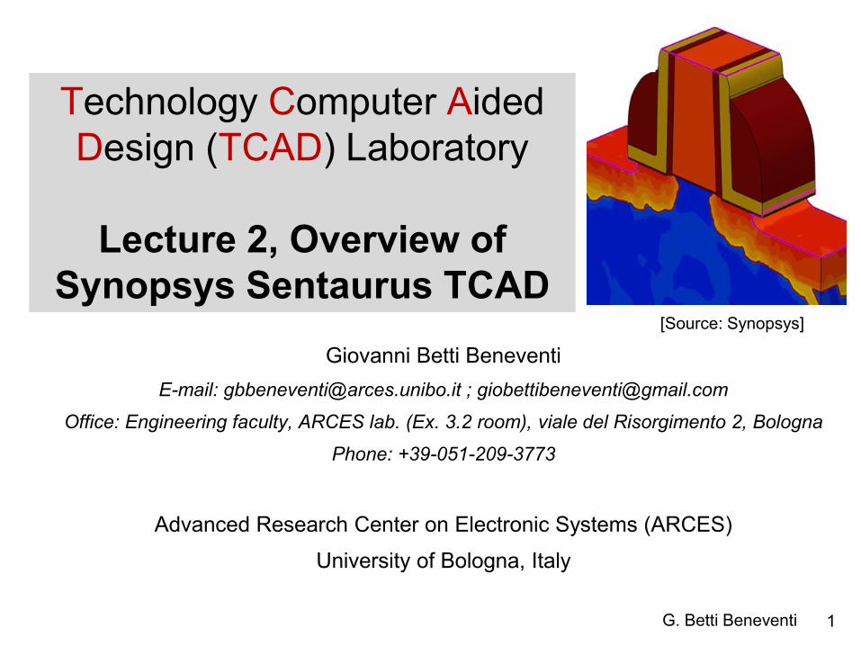
Synopsys TCAD Sentaurus tools
• Synopsys TCAD Sentaurus is a software suite made by several
tools (each one with its own programming language)
• The starting page of the Synopsys TCAD manual contains the link to
the manual of each tool, and can be opened by typing
cd ~ ; source .ISErc ; man_sen &

5 G. Betti Beneventi
Outline
• Sentaurus Tools
TCAD simulation flow
• Starting TCAD: Sentaurus Workbench
• Sentaurus Structure Editor
• Sentaurus Device
• Output examples
• Conclusion

6 G. Betti Beneventi
Modeling of semiconductor devices: typical flow
TCAD
PROCESS
SIMULATION
PROCESS
EMULATION
TCAD
DEVICE
SIMULATION
Spice-like
MODELING
TCAD DEVICE DESIGN
COMPACT MODELING ENABLES CIRCUIT DESIGN
Process Emulation. Process steps are not simulated but
emulated, i.e. the device structure is
realized through somewhat idealized
procedures that mimic real process
flow. Process emulation is used for
first order device analysis (e.g.
targeting a device for new specs.,
exploring new device concepts).
Process simulations can be done
once a new device architecture has
been optimized by means of device
simulation in order to (a) investigate
process non-idealities, (b) target
process specs.
Compact Modeling.
Compact modeling is a methodology
strictly related to TCAD. Once the
physics of the device has been
verified by TCAD, the device
electrical characteristics can be
“synthesized” by analytical functions
that can be physically-based or
simply behavioral. Compact
modeling is needed to provide the
“device model cards” to the circuit
designers for circuit simulations.

7 G. Betti Beneventi
Going through the DEVICE SIMULATION steps
Getting the device geometry and doping
concentrations (from process emulation)
Generating a grid (mesh) for numerical
computation
Solve for Poisson equations and current continuity
equations on the defined mesh
for some given boundary conditions
Visualizing the results
(both electrical results than internal quantities)
PRE-
PROCESSING
PROCESSING
POST-
PROCESSING
The description of physics
goes there

8 G. Betti Beneventi
Outline
• Sentaurus Tools
• TCAD simulation flow
Starting TCAD: Sentaurus Workbench
• Sentaurus Structure Editor
• Sentaurus Device
• Output examples
• Conclusion

9 G. Betti Beneventi
Loading the TCAD environment under Linux
1. Loading the environment variables and aliases
cd ~
source .ISErc
.ISErc is a configuration file stored in the home directory which contains some useful commands and settings:
# environmental variables
setenv PATH "${PATH}:/sw/CAD/TCAD/I_2013.12/bin"
setenv ISEROOT "/sw/CAD/TCAD/I_2013.12/bin"
setenv LM_LICENSE_FILE 27000@taricone
setenv STDB "/grp-proj-ares/nano/gbbeneventi/TCAD"
setenv OMP_NUM_THREADS 4
setenv NCPUS 4
# .exe
alias swb "/sw/CAD/TCAD/I_2013.12/bin/swb"
# manuals
alias man_sen "acroread /sw/CAD/TCAD/I_2013.12/tcad/current/manuals/PDFManual/front.pdf"
2. Launch Sentaurus Workbench (without “killing” the terminal)
swb &
where user’s SWB projects reside
max number of simultaneous threads
max number of CPUs used simultaneously code parallelization
tells OS how to get the license file
tells OS where finding out TCAD
software installation and executables
alias to launch SWB
alias to launch Sentaurus TCAD manual

10 G. Betti Beneventi
Sentaurus Workbench: general information
• It is the main tool interface which can be Windows-like controlled
• From Sentaurus Workbench (SWB) all the simulation flow can be controlled
• Simulations trees with variation of parameters in a matrix organization can be created
• An instance in the SWB tool is called “Project”
• When a project is saved, a directory is created. ASCII files containing the details of the saved project are created in the directory (in particular the gtree.dat file
contains the details of the simulation tree)
• Essential vocabulary to understand SWB operations:
– Scenario= to simplify the visualization, the whole simulation tree (the whole project) can be
divided in more than one scenario (it means that one project can be divided in more trees)
– Tool= one of the Sentaurus TCAD tools (e.g. sde, sdevice, inspect, etc.).
– Parameter= a variable (it can be a dimension, a physical property, a logic flag..)
– Experiment= a row in the simulation matrix
– Node= a point of the simulation matrix. Each point of the matrix is a “node”.
• Real node: node that can be executed (one for each tool). They are colored according to the execution
status of the corresponding simulation job
• Virtual node: node that cannot be executed
– Root= part of a row (i.e. of an experiment), from a given node to the left
– Leave= part of a row (i.e. of an experiment), from a given node to the right

11 G. Betti Beneventi
Sentaurus Workbench: configuration and shortcuts
Project Configuration Research
Research provides maximum flexibility, while Standard provides maximum level of consistency
Edit User Preferences Default View Options Show Pruned false
To prune a node means to cancel an experiment from the simulation tree
Scheduler Local jobs Maximum number of simultaneous jobs 10
The scheduler is the software tools which organizes the execution of the simulations
Scheduler Local jobs Default Nice Level 1
The lower the Default Nice Level (1 is the minimum value) the higher the priority by which the
simulation is running by the operating systems
F5 refresh
CTRL-P node preprocessing ; CTRL-R: node running ; CTRL-T abort node execution
F6 edit parameter value in a node
F6 node explorer
F9 show/un-show node number

12 G. Betti Beneventi
Sentaurus Workbench: useful commands
Project Operations Unlock
Unlock project blocking
Parameter Add
Add parameters
Experiments Create Default Experiments
To start a new trees: it creates the root experiment with default values parameters
Experiments Add New Experiment
To add a new experiment
[select a node] Nodes Extend Selection to Experiment Experiments
Add Values
To branch the trees by adding values to a selected experiment only
[select a node] Nodes Extend Selection to Leaves Nodes Prune
To cancel a branch in the experiment tree

13 G. Betti Beneventi
Sentaurus Workbench: use of @
To use parameters, those must be placed between a pair of @ in the tools
command files (see later). Example: for the BTBT flag to be an Sdevice variable, in the Sdevice command file BTBT must be indicated as @BTBT@
The pre-processing steps basically writes how many files how many are the project’s experiments, in each of them substituting the @BTBT@ with the
value of BTBT in the node corresponding to the given experiment.
Therefore, a pre-processing step is mandatory before an execution of a simulation
Although we have thoroughly review the most important feature, many other functionalities are available
in SWB (to name a few: include Tcl code blocks, cut & paste scenario’s blocks, conformity checks):
always refer to the user guide embedded in the manual front-page.

14 G. Betti Beneventi
Outline
• Sentaurus Tools
• TCAD simulation flow
• Starting TCAD: Sentaurus Workbench
Sentaurus Structure Editor
• Sentaurus Device
• Output examples
• Conclusion

15 G. Betti Beneventi
Sentaurus Structure Editor
• Tool that can be used for process emulation
• It allows defining
– device materials & geometry (1D,2D,3D)
– doping
– contacts
• Within Sentaurus Structure Editor (SDE), the meshing operation must also be
performed
• Better to use it in batch mode to increase program flexibility and power
• Input file where to write SDE command in text form must be named sde_dvs.cmd
• Once SDE is run, two files are produced:
nnodenumber_bnd.tdr for the visualization of the produced device geometry
nnodenumber_msh.tdr to visualize the device geometry & the numerical mesh
• The difficult part about SDE is of course not programming in itself, but understanding
and evaluating the simplification inherent to idealized geometry drawing !
• Also the choice of the numerical mesh is sometimes not at all trivial (critical for the
convergence of the numerical algorithm)
N.B. 3D TCAD simulations are available
in Sentaurus and much used especially
by industry (need of precise results on
particular application in which the device
process/geometry is usually well
known). On the other hand we will deal
only with 2D simulations, for the sake of
simplicity

16 G. Betti Beneventi
Outline
• Sentaurus Tools
• TCAD simulation flow
• Starting TCAD: Sentaurus Workbench
• Sentaurus Structure Editor
Sentaurus Device
• Output examples
• Conclusion

17 G. Betti Beneventi
Sentaurus Device
• Tool that defines the partial differential equations to be solved, i.e. it defines the physical model (e.g. the
drift-diffusion model, which consists in the Poisson equations and the current continuity equations)
• Boundary conditions (typically bias at the electrodes) must also be defined
• The material parameters of the physical model employed must be provided in a separate file
• It is possible to perform sweeps of the boundary conditions in order to get device electrical characteristics
• Also parameters for the numerical solvers implemented in the software must be defined
• Input files:
sdevice_des.cmd for physical models, boundary conditions and numerical parameters
sdevice.par to enter the model material parameters
• Output files:
nnodenumber_des.tdr for the visualization of the simulated physical quantities on the domain
nnodenumber.plt to visualize the device electrical characteristics
• The difficult part about SDEVICE is not programming in itself but understands the
simplification inherent to chosen physical model !
• It is in general difficult to understand which physical models must be accounted for
• Also the choice of material parameters and of the numerical parameters can be difficult
18 G. Betti Beneventi
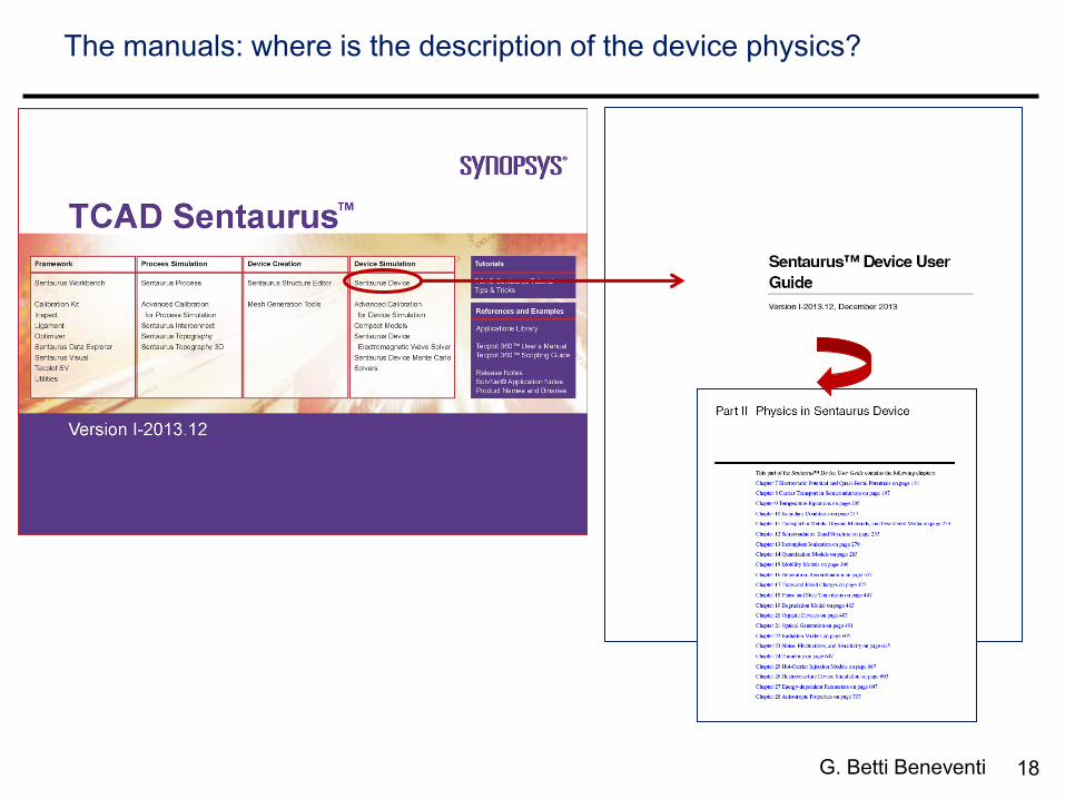
The manuals: where is the description of the device physics?
19 G. Betti Beneventi
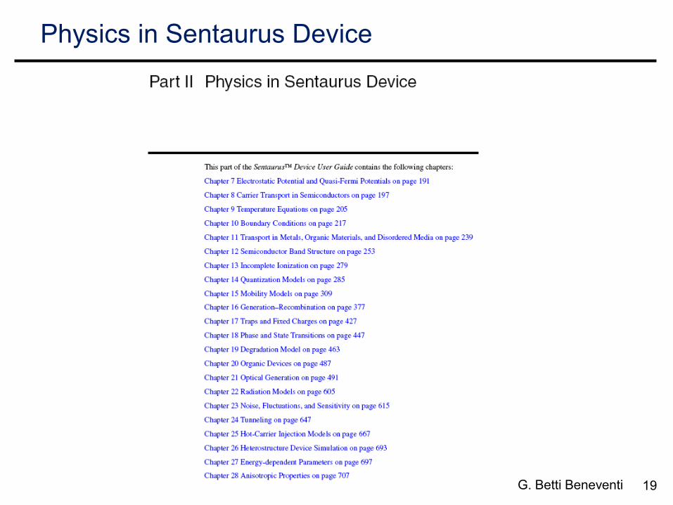
Physics in Sentaurus Device

20 G. Betti Beneventi
Outline
• Sentaurus Tools
• TCAD simulation flow
• Starting TCAD: Sentaurus Workbench
• Sentaurus Structure Editor
• Sentaurus Device
Output examples
• Conclusion

21 G. Betti Beneventi
Examples of simulation output
• .tdr files must be opened with Sentaurus Visual (Svisual)
• .plt files must be opened with Inspect
output of SDE simulation:
geometry, mesh and
doping concentration
(displayed with Svisual)
output of SDEVICE
simulation: electrostatic
potential (displayed with
Svisual)
output of SDEVICE: IV
characteristics of a pn
diode in forward bias
(displayed with
Inspect)
22 G. Betti Beneventi
Outline
• Sentaurus Tools
• TCAD simulation flow
• Starting TCAD: Sentaurus Workbench
• Sentaurus Structure Editor
• Sentaurus Device
• Output examples
Conclusion

23 G. Betti Beneventi
Conclusions
• Synopsys Sentaurus TCAD is the most developed software package for
TCAD simulations, in fact it has become the industry-standard
• It is a software suite, that is it contains several dedicated tools, each of them
having its own programming language
• Among the tools, the Sentaurus Workbench is the gateway that enables the
control of all the simulation flow
• Flow of a DEVICE TCAD simulation:
– creation of a geometry and of the numerical mesh
creating a numerical mesh for convergence cannot be trivial, frequently involving a trial-and-
error procedure (trade-off between convergence/accuracy and simulation time)
– choice of the physical models to be solved, of boundary conditions and material
parameters
which are the approximation inherent in the applied models? Are they acceptable?
– tweak of numerical parameters to assure convergence of numerical solution
as for numerical mesh, mainly based on trial and error/experience
– understands the output of the simulation
Which is, in essence, the results of the simulation? How things can be changed for better
performance/ to obtained the desired results?