Technological innovations - CERN Documents... · E. Pedroni Center for Proton Radiation Therapy -...
33
E. Pedroni Center for Proton Radiation Therapy - Paul Scherrer Institute - Proton Therapy Winter School 13 -01-2010 1 PSI 13.01.2010 Technological innovations Eros Pedroni Paul Scherrer Institute SWITZERLAND D. Meer, C. Bula, S, Safai, S. Zenklusen R. Kobler, S.Lin, …
Transcript of Technological innovations - CERN Documents... · E. Pedroni Center for Proton Radiation Therapy -...

E. Pedroni Center for Proton Radiation Therapy - Paul Scherrer Institute - Proton Therapy Winter School 13 -01-2010 1
PSI13.01.2010
Technological innovations
Eros Pedroni
Paul Scherrer InstituteSWITZERLAND
D. Meer, C. Bula,S, Safai, S. Zenklusen
R. Kobler, S.Lin, …
E. Pedroni Center for Proton Radiation Therapy - Paul Scherrer Institute - Proton Therapy Winter School 13-01-2010 2
1. Gantry layout 2. Fast scanning
3. Organ motion solutions 4. Competition or complement? ion therapy
5. Proton Radiography
6. Questions
Summary
E. Pedroni Center for Proton Radiation Therapy - Paul Scherrer Institute - Proton Therapy Winter School 13-01-2010 3
1. Gantry layout
E. Pedroni Center for Proton Radiation Therapy - Paul Scherrer Institute - Proton Therapy Winter School 13-01-2010 4
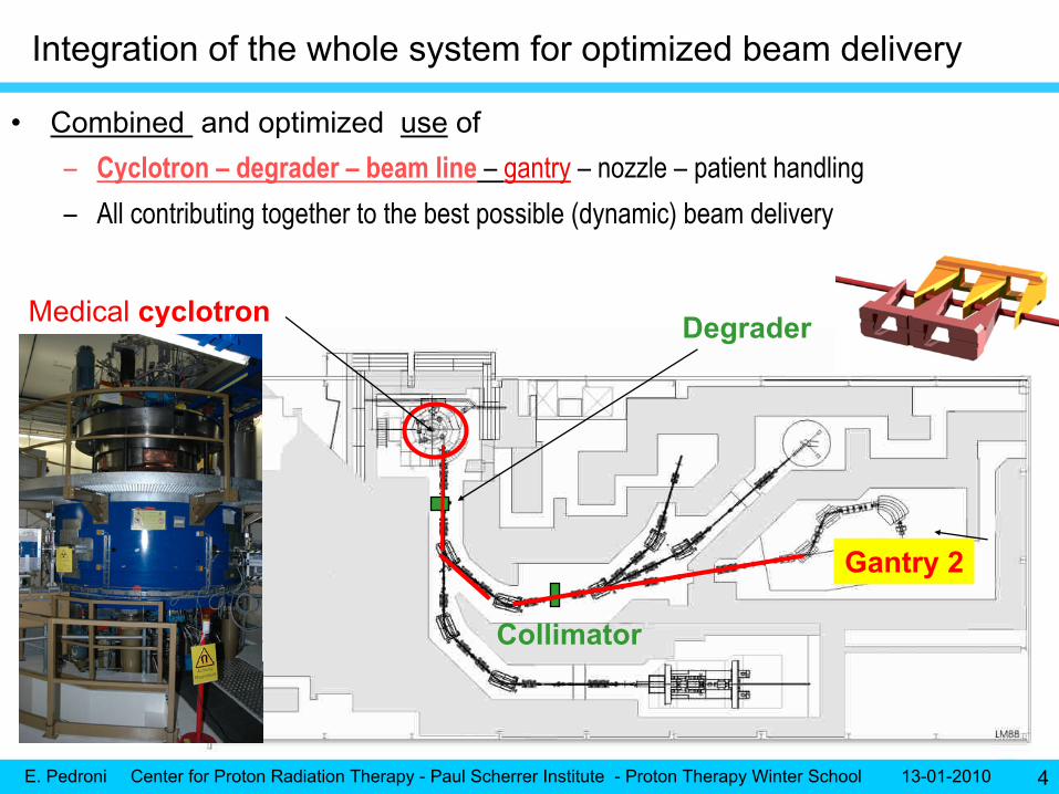
Medical cyclotron
Gantry 2
Degrader
Collimator
•
Combined and optimized use
of–
Cyclotron –
degrader –
beam line
–
gantry
–
nozzle –
patient handling
–
All contributing together to the best possible (dynamic) beam delivery
Integration of the whole system for optimized beam delivery
E. Pedroni Center for Proton Radiation Therapy - Paul Scherrer Institute - Proton Therapy Winter School 13-01-2010 5
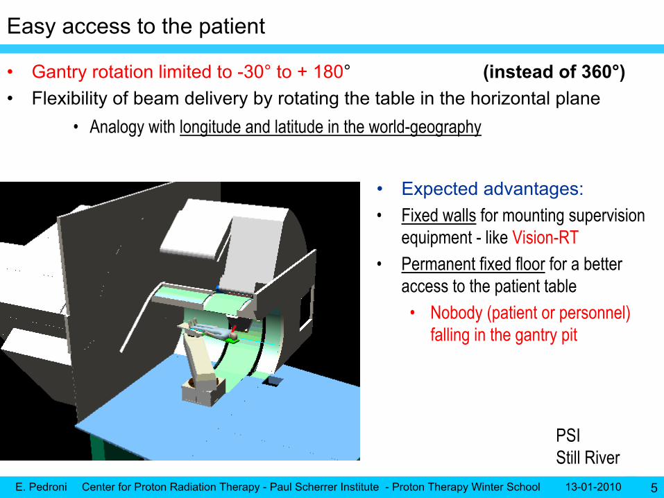
Easy access to the patient
•
Gantry rotation limited to -30°
to + 180°
(instead of 360°)•
Flexibility of beam delivery by rotating the table in the horizontal plane
•
Analogy with longitude and latitude in the world-geography
•
Expected advantages:•
Fixed walls
for mounting supervision
equipment -
like Vision-RT•
Permanent fixed floor
for a better
access to the patient table•
Nobody (patient or personnel) falling in the gantry pit
PSIStill River

E. Pedroni Center for Proton Radiation Therapy - Paul Scherrer Institute - Proton Therapy Winter School 13-01-2010 6
In-room positioning with sliding-CT
•
Within reach of the patient table–
Sliding CT of Siemens
–
Use of time-resolved images before (and after) treatment
•
Adapt dose field to the organ situation of the day (the body regions with soft tissues)
•
Setup of respiration gating
•
The first proton gantry of the world coupled with a sliding CT
•
Adaptive system to new diagnostic equipment
–
CT-PET? MRI?
E. Pedroni Center for Proton Radiation Therapy - Paul Scherrer Institute - Proton Therapy Winter School 13-01-2010 7
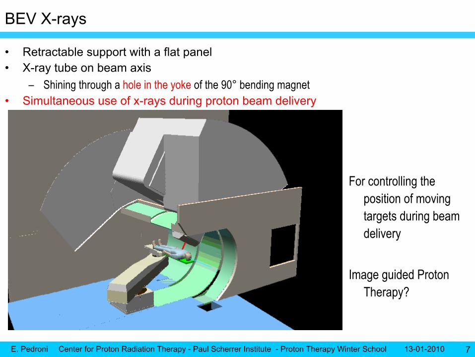
BEV X-rays
•
Retractable support with a flat panel•
X-ray tube on beam axis
–
Shining through a hole in the yoke
of the 90°
bending magnet•
Simultaneous use of x-rays during proton beam delivery
For controlling the position of moving targets during beam delivery
Image guided Proton Therapy?

E. Pedroni Center for Proton Radiation Therapy - Paul Scherrer Institute - Proton Therapy Winter School 13-01-2010 8
Option to use BEV X-ray -
simultaneous to proton beam?
•
Equivalent to portal imaging
with KV photon•
Large field-of-view area (26 cm x 16 cm) –
not masked by equipment or collimators
in the beam path
•
For QA control of gating and tracking (scanning + pulsed X-rays)•
Fluoroscopy?
•
Neutron damage to panel?
a) compact gantry b) long throw gantry
SweepersX rays tube
Proton beam
Bendingmagnet
nozzle
Yoke hole
PatientImager
Sweeper
or Scatterer
Collimator
Upstream scanningPSI
Downstream scanning
IBA Hitachi
Varian…

E. Pedroni Center for Proton Radiation Therapy - Paul Scherrer Institute - Proton Therapy Winter School 13-01-2010 9
•
Vacuum “up to the patient”–
Sharp pencil beam -
3 mm sigma
•
Two monitors and a strip monitor–
2 mm strips (delivered by TERA collaboration)
•
Removable pre-absorber–
IN and OUT of beam (motorized)
–
For ranges below 4 ? -10 ? cm•
Telescopic motion of the nozzle–
To reduce air gap
(keep patient at isocenter)
•
Option to add collimator and compensators–
To shield OAR on top of scanning
–
To simulate passive scattering with a scanning beam•
Collision protection to treat patients remotely (multiple fields in one go)–
Field extension with patient table
Optimized nozzle design

E. Pedroni Center for Proton Radiation Therapy - Paul Scherrer Institute - Proton Therapy Winter School 13-01-2010 10
Nozzle: preliminary results –
small size of pencil beam
•
Use of minimal material in the nozzle for keeping the beam size between 3 and 4 mm sigma at “all”
energies
•
The quality of the beam depends from the design of the beamline
and of the nozzle
Measured while removing piece by piecethe materials in the nozzle
mm
E. Pedroni Center for Proton Radiation Therapy - Paul Scherrer Institute - Proton Therapy Winter School 13-01-2010 11
2. Advancing the scanning technology
E. Pedroni Center for Proton Radiation Therapy - Paul Scherrer Institute - Proton Therapy Winter School 13-01-2010 12
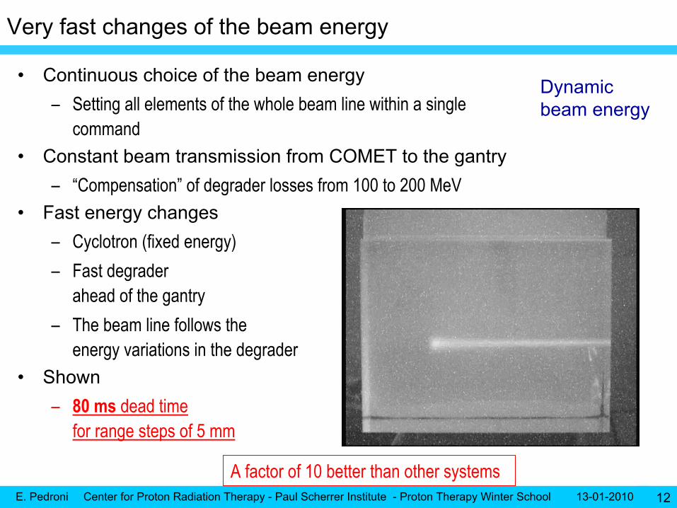
Very fast changes of the beam energy
•
Continuous choice of the beam energy–
Setting all elements of the whole beam line within a single command
•
Constant beam transmission from COMET to the gantry–
“Compensation”
of degrader losses from 100 to 200 MeV
•
Fast energy changes–
Cyclotron (fixed energy)
–
Fast degrader ahead of the gantry
–
The beam line follows the energy variations in the degrader
•
Shown–
80 ms
dead time
for range steps of 5 mm
Dynamic beam energy
A factor of 10 better than other systems
E. Pedroni Center for Proton Radiation Therapy - Paul Scherrer Institute - Proton Therapy Winter School 13-01-2010 13
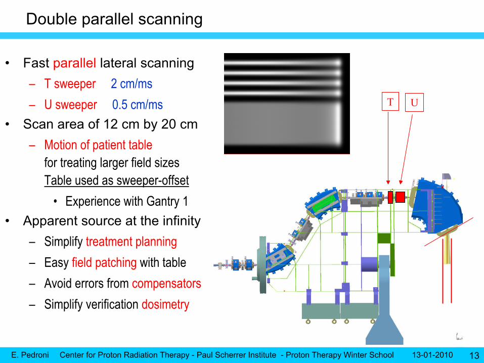
Double parallel scanning
T U
•
Fast
parallel lateral scanning–
T sweeper
2 cm/ms
–
U sweeper
0.5 cm/ms•
Scan area of 12 cm by 20 cm–
Motion of patient table
for treating larger field sizes Table used as sweeper-offset
•
Experience with Gantry 1•
Apparent source at the infinity–
Simplify treatment planning
–
Easy field patching with table–
Avoid errors from
compensators
–
Simplify verification
dosimetry

E. Pedroni Center for Proton Radiation Therapy - Paul Scherrer Institute - Proton Therapy Winter School 13-01-2010 14
100 MeV
120 MeV
140 MeV
160 MeV
180 MeV
200 MeV
Well focused beam for all energies…
•
Parallelism–
Max deviation ~4 mrad
(at edge of field)
Achieved by connecting a shortcorrection quadrupole
in series
with the U sweeper
E. Pedroni Center for Proton Radiation Therapy - Paul Scherrer Institute - Proton Therapy Winter School 13-01-2010 15
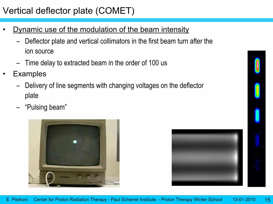
Vertical deflector plate (COMET)
•
Dynamic use of the modulation of the beam intensity–
Deflector plate and vertical collimators in the first beam turn after the ion source
–
Time delay to extracted beam in the order of 100 us•
Examples–
Delivery of line segments with changing voltages on the deflector plate
–
“Pulsing beam”
E. Pedroni Center for Proton Radiation Therapy - Paul Scherrer Institute - Proton Therapy Winter School 13-01-2010 16
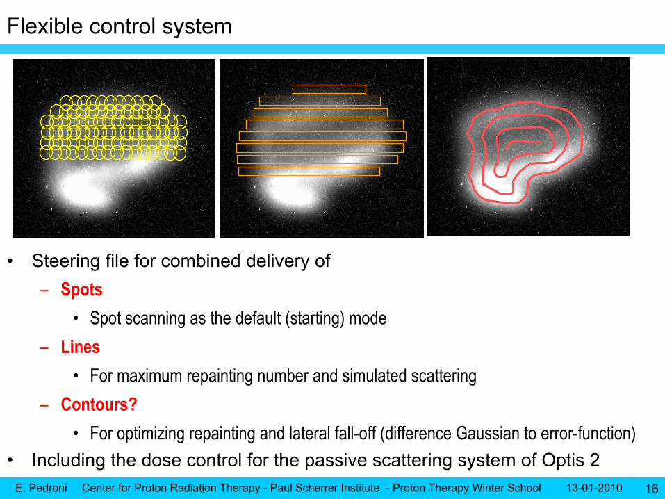
Flexible control system
•
Steering file for combined delivery of–
Spots
•
Spot scanning as the default (starting) mode–
Lines
•
For maximum repainting number and simulated scattering –
Contours?
•
For optimizing repainting and lateral fall-off (difference Gaussian to error-function) •
Including the dose control for the passive scattering system of Optis 2

E. Pedroni Center for Proton Radiation Therapy - Paul Scherrer Institute - Proton Therapy Winter School 13-01-2010 17
Tabulated dose delivery with FPGA
•
Combined tabulated control of –
U-sweeper
–
T-sweeper–
Beam intensity
•
As a function of timeT
U
Example 2
-
Dose box with continuous scanning 494 energy layers
(85 ms per layer)
(6 x 8 cm) in less than 1 minute
Example 1
–
U T meander path
E. Pedroni Center for Proton Radiation Therapy - Paul Scherrer Institute - Proton Therapy Winter School 13-01-2010 19
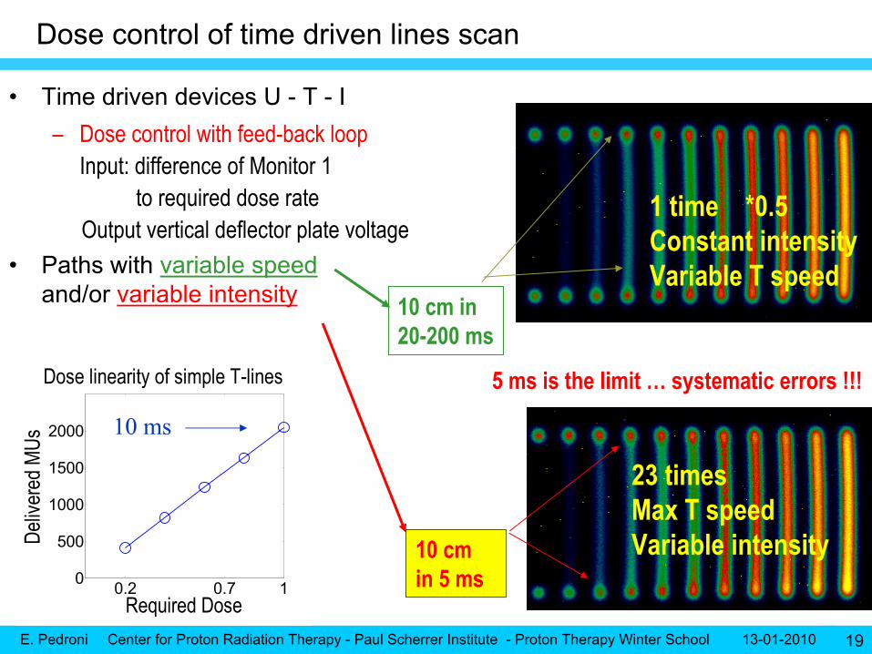
Dose control of time driven lines scan
•
Time driven devices U -
T -
I–
Dose control with feed-back loop Input: difference of Monitor 1
to required dose rate Output vertical deflector plate voltage
•
Paths with variable speed and/or variable intensity
0.2 0.7 10
500
1000
1500
2000
Required Dose
Deliv
ered
MUs
Dose linearity of simple T-lines
10 ms
23 timesMax T speedVariable intensity
1 time *0.5Constant intensityVariable T speed
10 cm in20-200 ms
10 cm in 5 ms
5 ms is the limit …
systematic errors !!!
E. Pedroni Center for Proton Radiation Therapy - Paul Scherrer Institute - Proton Therapy Winter School 13-01-2010 20
Conformal volumetric repainting
•
Painting of lines
(contours?)–
With maximal possible velocity ~ 2 cm / ms, 0.5 cm/ms
–
Dose shaping through Beam Intensity Modulation
(BIM)•
Painting of energy iso-layers –
< 200 ms per plane
(20 lines x 5 mm)
–
Change of energy (100 ms
-
5mm range)•
Repainting of iso-layers–
~ 6 s per liter
(20 energies at 5mm steps)
•
Volumetric repainting capability (aiming at)–
10 repaintings
/ liter in 1 or 2
minutes
–
Analogy with a TELEVISION tube
E. Pedroni Center for Proton Radiation Therapy - Paul Scherrer Institute - Proton Therapy Winter School 13-01-2010 21
3. Coping with the organ motion problem (of scanning)

E. Pedroni Center for Proton Radiation Therapy - Paul Scherrer Institute - Proton Therapy Winter School 13-01-2010 22
(Uncontrolled) motions less than 5 mm –
repainting
methods
• Scaled repainting•
Repeat same scan n times with dose divided by n
• Layered repainting•
Deliver partial scans with constant max. partial dose
•
Revisit only those spots which need more dose
• Volumetric repainting•
Repeat volumes
•
Requires fast energy changes
• Non volumetric repainting•
Repeat only iso-energy layers
beam
0 % missing
dose25 % missing
dose
75 % missing
dose50 % missing
dose
100 % missing
dose

E. Pedroni Center for Proton Radiation Therapy - Paul Scherrer Institute - Proton Therapy Winter School 13-01-2010 23
How many repaintings
do we need? Analysis of repainting strategies -
thesis work of S. Zenklusen –
(on press)
Full parameter space:• Frequency [1/min]: 2 -
100
• Start phase: 0 -
2π• tmax
[ms]: 1, 2, 3, 4, 5, 7,10, 20, 1000 → 2700 dose calculations
→ on PSI Linux ClusterStandard error reported for each dose distribution as difference to ∞-
repainting within the targetMotion amplitude 5 mmVolume 0.5 liter
G1 –
volumetric –
scaled repainingG2 –
volumetric –
scaled repainting
G2 –
volumetric –
iso-layer repaintingG2 –
volumetric –
lines
Volumetric repainting is important for the motion mitigation of scanning beams
Breast, pancreas, cervix, …
15 repainting in 1.5 minutes

E. Pedroni Center for Proton Radiation Therapy - Paul Scherrer Institute - Proton Therapy Winter School 13-01-2010 24
Respiration motion (> 5mm)
– Does gating
need repainting?
•
Only if residual motion error is small enough (we don’t known yet)
–
Which gating signal should we use?•
External signal (like thoracic strip ?)
•
3-d stereo viewing of external marks on patient skin?•
A whole energy layer delivered within a gate?
•
Needs fast iso-energy layer painting (50-200 ms per plane)–
Synchronize energy change to next gate
•
No need for fast energy changes•
But treatment time can be very high
Plan
1
Beam
Target at times ti
Iso-energylayers E at ti
E
E. Pedroni Center for Proton Radiation Therapy - Paul Scherrer Institute - Proton Therapy Winter School 13-01-2010 25
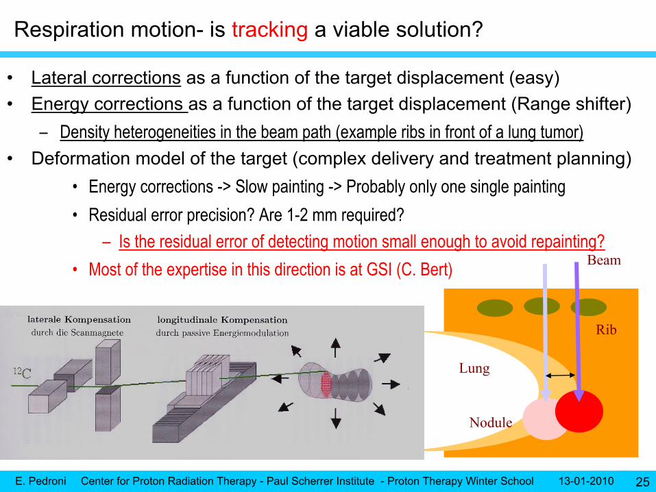
Respiration motion-
is tracking
a viable solution?
Nodule
Rib
Lung
•
Lateral corrections
as a function of the target displacement (easy)•
Energy corrections as a function of the target displacement (Range shifter)–
Density heterogeneities in the beam path (example ribs in front of a lung tumor)
•
Deformation model of the target (complex delivery and treatment planning)•
Energy corrections -> Slow painting -> Probably only one single painting
•
Residual error precision? Are 1-2 mm required?–
Is the residual error of detecting motion small enough to avoid repainting?
•
Most of the expertise in this direction is at GSI (C. Bert) Beam
E. Pedroni Center for Proton Radiation Therapy - Paul Scherrer Institute - Proton Therapy Winter School 13-01-2010 26
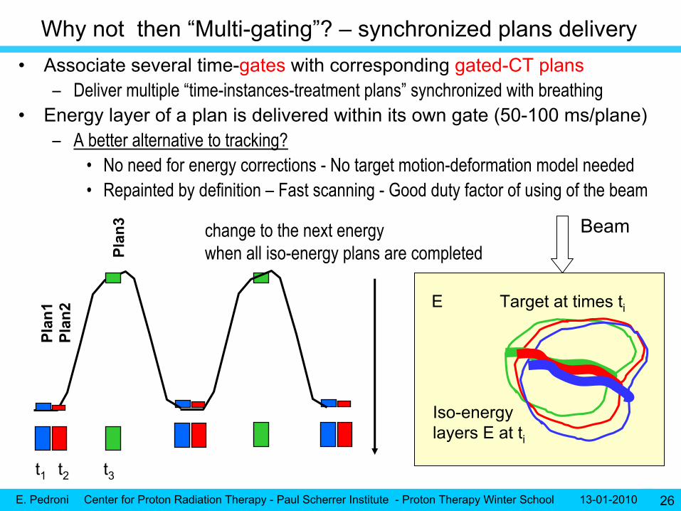
Why not then “Multi-gating”? –
synchronized plans delivery •
Associate several time-gates
with corresponding gated-CT plans
–
Deliver multiple “time-instances-treatment plans”
synchronized with breathing•
Energy layer of a plan is delivered within its own gate (50-100 ms/plane)–
A better alternative to tracking?
•
No need for energy corrections -
No target motion-deformation model needed •
Repainted by definition –
Fast scanning -
Good duty factor of using of the beam
t1 t2
Plan
1
Plan
3
Plan
2
change to the next energy when all iso-energy plans are completed
Beam
Target at times ti
Iso-energylayers E at ti
E
t3

E. Pedroni Center for Proton Radiation Therapy - Paul Scherrer Institute - Proton Therapy Winter School 13-01-2010 27
•
Small volume (<1/4 liter) –
Full volume treated within 4s with intensity modulated line scanning
–
Needs fast energy changes–
High dose rate
could be of advantage for reducing treatment time
•
Especially in the context of a hypo-fractionation•
A breath hold length of 5 s would then be sufficient–
Repainted, high efficiency, static planning, easier QA
Respiration motion (> 5mm)
Our preferred solution Whole painting within a breath hold cycle
Beam
Wholetarget
Breath hold
E. Pedroni Center for Proton Radiation Therapy - Paul Scherrer Institute - Proton Therapy Winter School 13-01-2010 28
Part 4. Competition with carbon ions

E. Pedroni Center for Proton Radiation Therapy - Paul Scherrer Institute - Proton Therapy Winter School 13-01-2010 29
The rationale of using carbon ions
•
Arguments in favor of carbon–
Correct -
The high LET of heavy ions could be of advantage for treating
•
Radio-resistant tumors•
Poorly oxygenated tumors
(OER oxygen enhancement ratio)
–
Correct –
Better precision of the beam -
Less MCS -
Sharper Bragg peaks –•
But with fractionation tails –
Large dose uncertainties due to the varying RBE
–
Simplistic -
Carbon is better because is “more effective”
(higher RBE) •
What matters is the RBE difference of healthy to tumor cells
–
the therapeutic ratio
–
Possibly wrong -
Carbon therapy “needs”
only few fractions –
is therefore less expensive•
Protons can also be delivered with low fractionation (small tumors –
radio-surgery)
•
At a high dose per fraction protons behave similar to high-LET (example OPTIS) •
Arguments against carbon–
High LET can be a contra-indication
(for example for pediatric treatments)
•
Absence of repair
of the healthy tissues
(tolerance within the target)•
Risk of late effects
(not convincing experience with neutrons and pions)
–
Assessment of the dose is difficult -
needs an own radiobiology research group
E. Pedroni Center for Proton Radiation Therapy - Paul Scherrer Institute - Proton Therapy Winter School 13-01-2010 30
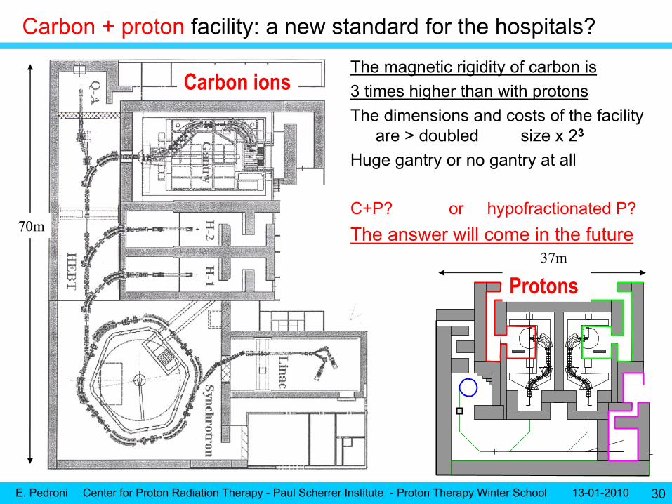
Carbon + proton
facility: a new standard for the hospitals?
70m
37m
Carbon
ions
Protons
The magnetic rigidity of carbon is 3 times higher than with protonsThe dimensions and costs of the facility
are > doubled size x 23
Huge gantry or no gantry at all
C+P? or hypofractionated
P?The answer will come in the future

E. Pedroni Center for Proton Radiation Therapy - Paul Scherrer Institute - Proton Therapy Winter School 13-01-2010 31
5. Other DEVELOPMENT topics”
(QA related)
E. Pedroni Center for Proton Radiation Therapy - Paul Scherrer Institute - Proton Therapy Winter School 13-01-2010 32
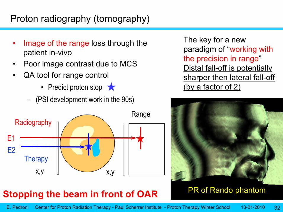
•
Image of the range
loss through the patient in-vivo
•
Poor image contrast due to MCS•
QA tool for range control
•
Predict proton stop–
(PSI development work in the 90s)
x,y x,y
Range
Therapy
Radiography
PR of Rando
phantom
E1E2
Proton radiography (tomography)
The key for a new paradigm of “working with the precision in range”Distal fall-off is potentially sharper then lateral fall-off (by a factor of 2)
Stopping the beam in front of OAR

E. Pedroni Center for Proton Radiation Therapy - Paul Scherrer Institute - Proton Therapy Winter School 13-01-2010 33
CONCLUSIONS
•
Proton therapy must remain competitive with conventional photon therapy–
IMPT
and scanning beams are needed to compete with IMRT
–
PT will have to follow the development towards image-guided RT–
Scanning is most optimal
•
for biological targeting
(intentional non-homogeneous dose distributions) •
and adaptive beam delivery
•
The experience of using scanning with organ motion
is still missing–
Fast volumetric repainting and volume within a breath-hold
could be an “easy”
solution of this problem
•
Initiatives to reduce the size and costs of the equipment (new accelerators)–
are welcome … but difficult to achieve …
at equal performance
•
Is high-LET radiation a true clinical need?–
More clinical research with ions needed
–
Superconducting cyclotron and gantries could help ion therapy
E. Pedroni Center for Proton Radiation Therapy - Paul Scherrer Institute - Proton Therapy Winter School 13-01-2010 34
THANK YOU