Techno-economic analysis of the thermal energy saving ...
18
Contents lists available at ScienceDirect Applied Energy journal homepage: www.elsevier.com/locate/apenergy Techno-economic analysis of the thermal energy saving options for high- voltage direct current interconnectors Alessandro Giampieri a , Zhiwei Ma a , Janie Ling Chin a , Andrew Smallbone a, ⁎ , Padraig Lyons a , Imad Khan b , Stephen Hemphill c , Anthony Paul Roskilly a a Sir Joseph Swan Centre for Energy Research, Newcastle University, Newcastle upon Tyne NE1 7RU, UK b Siemens, Faraday House, Sir William Siemens Square, Frimley, Camberley GU16 8QD, UK c Mutual Energy, 85 Ormeau Rd, Belfast BT7 1SH, UK HIGHLIGHTS • High-voltage direct current interconnectors are used for long-distance electricity transfer. • They transfer 100 s GW of electrical power with around 1% losses mainly to heat. • This paper compares alternative solutions for heat recovery and reutilisation. • Data from the Moyle interconnector between Scotland and Northern Ireland is used. • Heat-to-electricity and heat-to-cooling technologies are compared. ARTICLE INFO Keywords: High-voltage direct current conversion station Low-grade heat recovery Moisture control Electricity production Economic factor ABSTRACT High-voltage direct current interconnection stations are increasingly used for long-distance electricity transport worldwide, due to efficiency and economic reasons. The identification and evaluation of cost-effective waste heat sources appropriate for recovery and reutilisation represent an opportunity that can improve the efficiency of high-voltage direct current stations, resulting in significant savings in energy consumption and reduction of the carbon footprint. The paper is the first to investigate the technological and economic feasibility of heat recovery at a major interconnector power station. Once identified the potential recoverable heat sources and evaluated the latest advancements in thermal energy recovery technology, a technological and economic ana- lysis of two potential heat recovery strategies has been performed. While the heat-to-electricity technology was proved to be technologically but not economically feasible, the realisation of a combined liquid desiccant and evaporative cooling heat recovery strategy was proved to present the best economic performance with a payback period of about 5 years and a levelised cost of saved energy of 0.155 €/kWh, depending on the heat recovery and size of the system. Additional economic savings can be obtained for high-voltage direct current stations located in hot and humid climates, where the moisture removal ability of liquid desiccant technology could be parti- cularly advantageous. 1. Introduction High-voltage direct current (HVDC) transmission lines are increas- ingly used all over the world for the efficient transportation of electric power over long distances. HVDC interconnector stations represent a specialized type of substation which forms the terminal equipment for an HVDC transmission line. They are used for the conversion of elec- tricity from AC (alternating current) to DC (direct current) at the transmitting end, and back again from DC to AC at the receiving end, based on the use of the thyristor valves [1]. The reason behind the utilisation of DC current for the long-distance transport of electricity is to be found in the lower cost and electrical losses compared to AC current. Whereas, the transport over shorter distances in underground or submarine cables are more advantageous from an economic view- point [1]. Additional benefits of HVDC systems are improved power flow control, and other added benefits related to stability and electrical power quality [2]. In recent years, the utilisation of interconnector power stations has https://doi.org/10.1016/j.apenergy.2019.04.003 Received 12 November 2018; Received in revised form 14 March 2019; Accepted 7 April 2019 ⁎ Corresponding author. E-mail address: [email protected] (A. Smallbone). Applied Energy 247 (2019) 60–77 0306-2619/ © 2019 The Authors. Published by Elsevier Ltd. This is an open access article under the CC BY license (http://creativecommons.org/licenses/BY/4.0/). T
Transcript of Techno-economic analysis of the thermal energy saving ...

Contents lists available at ScienceDirect
Applied Energy
journal homepage: www.elsevier.com/locate/apenergy
Techno-economic analysis of the thermal energy saving options for high-voltage direct current interconnectors
Alessandro Giampieria, Zhiwei Maa, Janie Ling China, Andrew Smallbonea,⁎, Padraig Lyonsa,Imad Khanb, Stephen Hemphillc, Anthony Paul Roskillya
a Sir Joseph Swan Centre for Energy Research, Newcastle University, Newcastle upon Tyne NE1 7RU, UKb Siemens, Faraday House, Sir William Siemens Square, Frimley, Camberley GU16 8QD, UKcMutual Energy, 85 Ormeau Rd, Belfast BT7 1SH, UK
H I G H L I G H T S
• High-voltage direct current interconnectors are used for long-distance electricity transfer.
• They transfer 100 s GW of electrical power with around 1% losses mainly to heat.
• This paper compares alternative solutions for heat recovery and reutilisation.
• Data from the Moyle interconnector between Scotland and Northern Ireland is used.
• Heat-to-electricity and heat-to-cooling technologies are compared.
A R T I C L E I N F O
Keywords:High-voltage direct current conversion stationLow-grade heat recoveryMoisture controlElectricity productionEconomic factor
A B S T R A C T
High-voltage direct current interconnection stations are increasingly used for long-distance electricity transportworldwide, due to efficiency and economic reasons. The identification and evaluation of cost-effective wasteheat sources appropriate for recovery and reutilisation represent an opportunity that can improve the efficiencyof high-voltage direct current stations, resulting in significant savings in energy consumption and reduction ofthe carbon footprint. The paper is the first to investigate the technological and economic feasibility of heatrecovery at a major interconnector power station. Once identified the potential recoverable heat sources andevaluated the latest advancements in thermal energy recovery technology, a technological and economic ana-lysis of two potential heat recovery strategies has been performed. While the heat-to-electricity technology wasproved to be technologically but not economically feasible, the realisation of a combined liquid desiccant andevaporative cooling heat recovery strategy was proved to present the best economic performance with a paybackperiod of about 5 years and a levelised cost of saved energy of 0.155 €/kWh, depending on the heat recovery andsize of the system. Additional economic savings can be obtained for high-voltage direct current stations locatedin hot and humid climates, where the moisture removal ability of liquid desiccant technology could be parti-cularly advantageous.
1. Introduction
High-voltage direct current (HVDC) transmission lines are increas-ingly used all over the world for the efficient transportation of electricpower over long distances. HVDC interconnector stations represent aspecialized type of substation which forms the terminal equipment foran HVDC transmission line. They are used for the conversion of elec-tricity from AC (alternating current) to DC (direct current) at thetransmitting end, and back again from DC to AC at the receiving end,
based on the use of the thyristor valves [1]. The reason behind theutilisation of DC current for the long-distance transport of electricity isto be found in the lower cost and electrical losses compared to ACcurrent. Whereas, the transport over shorter distances in undergroundor submarine cables are more advantageous from an economic view-point [1]. Additional benefits of HVDC systems are improved powerflow control, and other added benefits related to stability and electricalpower quality [2].
In recent years, the utilisation of interconnector power stations has
https://doi.org/10.1016/j.apenergy.2019.04.003Received 12 November 2018; Received in revised form 14 March 2019; Accepted 7 April 2019
⁎ Corresponding author.E-mail address: [email protected] (A. Smallbone).
Applied Energy 247 (2019) 60–77
0306-2619/ © 2019 The Authors. Published by Elsevier Ltd. This is an open access article under the CC BY license (http://creativecommons.org/licenses/BY/4.0/).
T
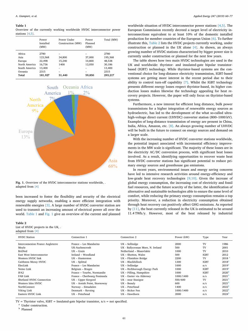
been increased to foster the flexibility and security of the electricalenergy supply networks, enabling a more efficient integration withrenewable energies [3]. A large number of HVDC converter station areused to transmit an increasing amount of electrical power all over theworld. Table 1 and Fig. 1 give an overview of the current and planned
worldwide situation of HVDC interconnector power stations [4,5]. TheEuropean Commission recently decreed a target level of electricity in-terconnections equivalent to at least 10% of the domestic installedproduction for member countries of the European Union [6]. To furtherillustrate this, Table 2 lists the HVDC projects currently working, underconstruction or planned in the UK alone [4]. As shown, an alwaysgrowing number of HVDC stations characterised by bigger power size iscurrently under construction or planned for the next few years.
The table shows how two main HVDC technologies are used in theUK and worldwide: thyristor- and insulated-gate bipolar transistor-based (IGBT) technology. While thyristor-based systems are the con-ventional choice for long-distance electricity transmission, IGBT-basedsystems are getting more interest in the recent period due to theirability to control turn-off capability [7]. Whilst the IGBT technologypresents different energy losses respect thyristor-based, its higher con-duction losses makes likewise the technology appealing for heat re-covery projects. However, the paper will only focus on thyristor-basedsystems.
Furthermore, a new interest for efficient long distance, bulk powertransmissions for a higher integration of renewable energy sources ashydroelectric, has led to the development of the what so-called ultra-high-voltage direct current (UHVDC) converter station (800–1000 kV).Examples of long-distance transmission of energy are present in China,India, Africa, Amazon, etc. [8]. An always growing number of UHVDCwill be built in the future to connect on energy sources and demand ona larger scale.
With the increasing number of HVDC converter stations worldwide,the potential impact associated with incremental efficiency improve-ments in the MW scale is significant. The majority of these losses are inthe electricity AC/DC conversion process, with significant heat lossesinvolved. As a result, identifying opportunities to recover waste heatfrom HVDC converter stations has significant potential to reduce pri-mary energy sources and greenhouse gas emissions.
In recent years, environmental issues and energy saving concernshave led to intensive research activities around energy-efficiency andlow-grade heat recovery technologies [9,10]. Given the increase ofglobal energy consumption, the increasing cost of electricity and fossilfuel resources, and the future scarcity of the latter, the identification ofalternative and sustainable technologies able to ensure the same level ofcomfort, while reducing the primary energy consumption remains a toppriority. Moreover, a reduction in electricity consumption obtainedthrough heat recovery can positively affect GHG emissions. As reportedby [11], the heat currently released in the UK is estimated to be around11.4 TWh/y. However, most of the heat released by industrial
Table 1Overview of the currently working worldwide HVDC interconnector powerstations [4,5].
PowerInstalled(MW)
Power UnderConstruction (MW)
PowerPlanned(MW)
Total (MW)
Africa 2780 – – 2780Asia 123,568 34,800 37,000 195,368Europa 22,498 15,240 10,800 48,538North America 16,736 1400 12,050 30,186South America 13,400 – – 13,400Oceania 2315 – – 2315Total 181,927 51,440 59,850 293,217
Fig. 1. Overview of the HVDC interconnector stations worldwide, .adapted from [4]
Table 2List of HVDC projects in the UK, .adapted from [4]
HVDC Station Connection 1 Connection 2 Power (kW) Type Year
Interconnexion France Angleterre France – Les Mandarins UK – Sellindge 2000 TV 1986Moyle UK-Auchencrosh UK - Ballycronan More, N. Ireland 500 TV 2001BritNed UK – Grain Netherland – Maasvlakte 1000 TV 2010East West Interconnector Ireland – Woodland UK – Shotton, Wales 500 IGBT 2012Western HVDC link UK – Hunterston UK – Flintshire Bridge 2200 TV 2018 a
Caithness Moray HVDC UK – Splittal UK – Blackhillock 1200 IGBT 2018a
ElecLink France – Les Mandarins UK – Sellindge 1000 n/s 2019a
Nemo Link Belgium – Bruges UK – Richborough Energy Park 1000 IGBT 2019a
IFA2 France – Tourbe, Normandie UK – Pilling, Hampshire 1000 IGBT 2020b
FAB Link France – Cherbourg Peninsula UK – Exeter via Alderney 1000/1400 n/s 2021b
Shetland HVDC Connection UK – Upper Kergord UK – near Staxigoe 550/600 TV 2021b
Western Isles HVDC UK – Arnish Point, Stornoway UK – Beauly 600 n/s 2021b
NorthConnect Norway – Simadalen UK – Peterhead 1400 n/s 2022b
Viking Link Denmark – Revsing UK – Bicker Fen 1000/1400 n/s 2022b
Eastern HVDC Link UK – Peterhead UK – Hawthorn 2000 n/s 2024b
TV=Thyristor valve, IGBT= Insulated-gate bipolar transistor, n/s= not specified.a Under construction.b Planned
A. Giampieri, et al. Applied Energy 247 (2019) 60–77
61
processes, data centers, etc. is low-grade with a temperature lower than200 °C [12]. This is analogous to the case of HVDC interconnector sites,where the reported temperatures of the waste heat produced by thecomponents most responsible for heat losses, transformers and thyristorvalves, is lower than 100 °C. The recovery of waste heat in this tem-perature range is often economically unfeasible and must be carefullyevaluated. The identification and evaluation of technologies able toeconomically recover and utilise the waste heat present at a powerinterconnector site is the core aim of this paper.
The novelty of this work is that it represents the first detailed eva-luation of potential technologies for the recovery of low-grade wasteheat from the power conversion equipment of HVDC interconnectors.This evaluation will be underpinned by technical performance dataprovided by the Moyle interconnector substation, transmitting powerbetween Scotland and Northern Ireland. Technological and economicassessment of the feasibility of the recovery and use of the waste heatproduced by thyristors valves and transformers is carried out. Betweenthe different active heat recovery technologies, two strategies areconsidered in the paper: technologies for waste heat utilisation toproduce cooling and dehumidification (liquid desiccant and solid de-siccant systems coupled with evaporative cooling), and technologies forelectricity production, based on a combination of waste heat upgradingtechnology, e.g. absorption heat transformers (AHT), and conversion ofwaste heat in electricity, e.g. Organic Rankine Cycle (ORC) systems.Therefore, the paper is structured as follows: Section 2 defines the scopeof the paper and the methodology used for the technological and eco-nomic analysis, investigating the possible heat recovery technologiesand classifying the different technologies in thermally-driven air-con-ditioning technologies (liquid desiccant, solid desiccant, and evapora-tive cooling) and power generation (combination of heat upgrade withAHT and electricity production with ORC). Section 3 identifies the heatsources present at the Moyle HVDC interconnector site, particularlydescribing the thyristor valves and transformer and the unexploitedheat currently wasted. Section 4 evaluates the technological perfor-mance of the identified heat recovery strategies. In Section 5, thetechnological challenges for the retrofitting on the Moyle interconnec-tion site are described and two different heat recovery strategies (usingair or water as heat transfer medium) are identified. To conclude with,the economic analysis of the two identified heat recovery strategies isperformed (Section 6).
2. Scope and methodology
The paper aims to evaluate from a technological and economic pointof view the potential heat recovery strategies possible at HVDC con-verter stations. Given the scale of the power transmitted through HVDCstations and the significant heat losses present, the implementation ofheat recovery would result in significant economic benefits for HVDCmanufacturers. The methodology used in the study is shown in Fig. 2.
2.1. Literature review of heat recovery options
A detailed analysis of the major technologies for waste heat re-covery and utilisation was conducted, including power generationtechnologies (ORC, Kalina cycle and thermoelectric power generation),heating technologies (direct space heating, district heating, heat pump),heat-to-cooling technologies (absorption cooling, adsorption cooling,desiccant evaporative cooling, ejector cooling), and some thermal up-grade technologies (such as solar thermal booster and absorption heattransformer).
The range of economically viable potential recovery technologies islimited by their low operational temperatures. Through an evaluationof the Moyle interconnector site’s landscape and of the possible do-mestic or local application of the heat recovery, only cooling and powergeneration technologies were considered favourable in the currentstudy, given the very little heat demand at the station or around. A
summary of the advantages and drawbacks of the identified heat re-covery strategies is displayed in Table 3. The potential heat recoverystrategies are further described in the next paragraphs.
2.1.1. Humidity removal and cooling by desiccant technologyDesiccants are substances characterized by their hygroscopic prop-
erty, namely their affinity to water molecules. These substances are ableto efficiently dehumidify the air, sorbing the water molecules present init. Depending on their physical state, desiccants can be classified insolid and liquid. The two desiccant categories differ for the physics oftheir water sorption process, namely absorption for liquid and ad-sorption for solid desiccants [13]. Their regeneration process (deso-rption of water molecules to a scavenging air stream) is driven by heat,obtainable by renewable energies, such as solar-thermal, geothermal,etc., or recovered by industrial processes.
2.1.1.1. Liquid desiccant and evaporative cooling system. Liquiddesiccants are hygroscopic solutions characterised by a lowequilibrium vapour pressure, able to absorb water molecules from theoutdoor air. Different typologies of solution can be employed asdesiccant, such as halide salt solutions (LiCl, LiBr, CaCl2, etc.),triethylene glycol (TEG), potassium formate (HCO2K), and ionicliquids. Each of these desiccant solutions presents differentthermodynamic properties and cost. The choice of the desiccantsolution used is decisive for the overall performance of the system[14]. As noted above, the LDAC system is able to efficiently dehumidifythe air and deal with latent loads of buildings and humidity removalapplications. However, this technology is usually not able to coversensible loads of buildings and is hence integrated with additional air-cooling systems [15,16], such as electrically-driven vapourcompression chiller (hybrid system) [17], absorption chillers [18],and evaporative cooling systems [19], direct or indirect. In this study,the combination of liquid desiccant with direct evaporative cooling wasconsidered. The schematic diagram of the system is shown in Fig. 3.
As shown in the Figure, the cold strong desiccant solution is sprayedfrom the top of the dehumidifier, contacting the air that is blown fromthe bottom. As the solution and air contact, the liquid desiccant willtend to drive off the moisture from the air stream. The driving force ofthe process is the low equilibrium vapour pressure of the solution re-spect the partial vapour pressure of water molecules in the air. Themigration of water molecules from the air to desiccant solution con-tinues until the solution reaches equilibrium with the air. In the re-generator, the opposite process happens, as the hot weak desiccantsolution desorbs water to the counter-current (or cross-current) flowscavenging air, becoming again a strong solution. For the absorption/desorption process to happen, the solution must be cooled/heated be-fore entering the dehumidifier/regenerator, respectively. The heatingsource can be obtained by renewable energies or waste heat recovery,while the cooling source is usually a cooling tower. The air after beingdehumidified by the liquid desiccant air-conditioning system is cooledby an evaporative cooling system and then supplied to the air-condi-tioned zone. Depending on the temperature and humidity requirementsand costs, a direct or indirect evaporative cooler can be used in com-bination with liquid desiccant technology. When a direct evaporativecooler is used, water evaporates into the dry air with consuming sen-sible heat from both water itself and dry air. Then the dry air becomescool wet air ready to be supplied to the air-conditioned zone.
2.1.1.2. Solid desiccant and evaporative cooling system. Solid desiccantsare materials able to physically adsorb water molecules that condenseinside the surface of the adsorbent material, such as silica gel, zeolite,synthetic zeolites, activated alumina, carbons, synthetic polymers,CaCl2/LiCl/LiBr composite with supporting material, etc. [20]. Thedesiccant material is usually embedded in a wheel configuration to easethe regeneration process [21]. Fig. 4 depicts an example of soliddesiccant wheel combined with an evaporative cooling system.
A. Giampieri, et al. Applied Energy 247 (2019) 60–77
62

In the system, a desiccant rotary wheel is integrated with a heatrecovery wheel and a direct evaporative cooler to reach the desiredcondition for the building’s supply air. As the process air passes throughthe desiccant wheel, it releases humidity to the desiccant wheel. Thisideal process performed by solid desiccant is isenthalpic, resulting in atemperature increase of the dehumidified air. As the desiccant wheelrotates, the desiccant material is heated and regenerated, desorbing thewater vapour previously absorbed into the air exhausted by the room.The warm dry air produced by the desiccant wheel is then pre-cooled ina heat recovery wheel, which has also the function of pre-heating the
return air, reducing the heating consumption for the desiccant wheelregeneration. Additional cooling is provided by the evaporative cooler,where the dry air becomes cool wet air that can be delivered to thebuilding. The return air exhausted from the room passes through an-other evaporative cooler first and then releases its cool energy to thewarm dry air in the heat recovery exchanger.
2.1.2. Heat upgrade and power generationProduction of electricity with an organic Rankine cycle (ORC)
system driven by the heat upgraded by an absorption heat transformer
Fig. 2. Methodology used in the study.
Table 3Benefits and drawbacks of the identified heat recovery strategies.
Cooling Heating Power generation
Advantages Cooling demand is large Direct usage Flexible energy formDisadvantages Waste heat temperature is not high Heating demand is low Waste heat temperature is too low; upgrade is necessaryPotential technology Desiccant evaporative cooling – Absorption heat transformer and organic Rankine cycle
Fig. 3. Schematic diagram of a combined liquid desiccant and direct evaporative cooling system.
A. Giampieri, et al. Applied Energy 247 (2019) 60–77
63

(AHT) is the second identified heat recovery strategy at Moyle inter-connector. The main components are further described.
2.1.2.1. Absorption heat transformer. AHT technology is used to boostthe waste heat temperature, producing higher quality heat that wouldotherwise have been mostly produced with fossil-based energy sources.The AHT working principle is the reverse of an absorption chiller [22].The general schematics of the system in single and double stageconfiguration is displayed in Fig. 5. The main components of thesystem are generator, absorber, evaporator, condenser, and solutionheat exchanger.
As represented in the Figure, the low-temperature heat source(lower than 100 °C) is supplied at the same temperature to evaporatorand generator, at the same time or to the evaporator first and then tothe generator. In the condenser, the working fluid is condensed atambient temperature releasing heat at low-temperature. The usefuleffect of the system is the heat is released in the absorber, which is at ahigher temperature due to the higher pressure. As a result, the inputwaste heat can be upgraded to a high temperature and collected at theabsorber for a more efficient utilisation [23]. Different working fluidshave been used in AHTs, such as LiBr-H2O, NH3-H2O, and H2O-Carrol (amixture of LiBr-Ethylene Glycol in ratio 1:4–5wt) [24]. The employ-ment of different working fluids strongly influences the overall per-formance of the system and therefore must be carefully evaluated. Forthe determination of the thermal performance of an AHT, the coeffi-cient of performance COP is used and defined as [25]:
=+
COP QQ Q
abs
evap cond (1)
where Qabs, Qevap, and Qcond represent the heat released or absorbed bythe absorber, evaporator, and condenser, respectively. The temperaturelift ΔT achievable by the AHT at the absorber is defined as [26]:
= −T T TΔ abs evap (2)
where Tabs and Tevap represent the temperature at the absorber andevaporator, respectively. Common values for the temperature lift thatcan be obtained with a single-stage AHT are around 30–40 °C [25]. Thisfeature of single-stage AHT limits the employment of the technology. Asignificant increase in the temperature lift can be reached using adouble-stage AHT [25].
2.1.2.2. Organic Rankine Cycle. Organic Rankine Cycle (ORC) is a heatconversion technology able to convert low-temperature heat intoelectricity. These systems use organic fluids as working fluid of thesystem. These fluids are characterised by a lower boiling point respectsteam, increasing the useful work of the system (electricity production)when dealing with low-temperature heat [27]. The use of differentworking fluids strongly influences the performance and economics ofthe system [28]. The configuration of a typical ORC system is illustratedin Fig. 6.
The working principle of ORC is the same of the Rankine cycle. Theworking fluid is pumped to a boiler where it is evaporated as it passes
Fig. 4. Schematic diagram of a combined rotary wheel solid desiccant dryer and direct evaporative cooling system.
Fig. 5. Schematic diagram of single stage (left) and double stage (right) absorption heat transformer.
A. Giampieri, et al. Applied Energy 247 (2019) 60–77
64

through an expansion device (turbine or other expanders), generatingpower. The working fluid at the outlet of the expansion device passesthrough a condenser heat exchanger where it is finally re-condensed.The liquid working fluid is again pressurized by the pump, closing theORC cycle [29]. Respect the Rankine cycle, the lower working tem-perature of an ORC makes this technology particularly interesting forthe conversion of low-temperature waste heat into electricity.
Today’s energy-saving concerns have facilitated the development ofORC technology for employment of low-temperature heat sources, suchas renewable energy (solar energy, geothermal heat, biomass, etc.) orrecovered by industrial waste heat, to produce electricity [30]. The heatrecovery strategy based on the combination of AHT and ORC is of re-cent interest [31].
2.2. Economic analysis
The cost-effectiveness of the technology replacement for the low-grade heat recovery was evaluated using two different metrics: thepayback period and the levelised cost of saved electricity. The paybackperiod represents a simple comparison between capital and operationalcosts of the conventional and replacement technology and to identifythe economic return on the investment and is defined as:
=−
−Payback period
CAPEX CAPEXOPEX OPEX
repl conv
conv repl (3)
where CAPEXrepl and CAPEXconv, and OPEXrepl and OPEXconv representthe capital and operational cost of the replacement and conventionaltechnology, respectively. Whereas the levelised cost of saved electricity(LCOSE), indicates the cost for saving each kilowatt hour of electricenergy by replacing the conventional system over the lifespan of themachine. The LCOSE is defined as [32]:
= =− + ∑
∑
= +
=
−
+
LCOSE InvestmentElectricity saved
CAPEX CAPEX [ ]
[ ]
repl conv kn OPEX
i
kn Elec Elec
i
1 (1 )
1 (1 )
replk
conv replk
(4)
The parameter evaluates the economic viability of the technologyreplacement over the lifespan of the machinen, assumed as 20 years.Elecconv and Elecrepl represent the electricity consumed in kWh by con-ventional and replacement technology. The discount rate i is assumedas 3% [32].
3. Moyle interconnector station and waste heat sourcesidentification
3.1. Moyle interconnector station
Went into service in 2001, the HVDC Moyle interconnector links theelectricity grid between Auchencrosh, Scotland, and Ballycronan More,Northern Ireland. Its geographic location and schematic diagram aredisplayed in Fig. 7 [33]. This interconnection station consists of twomonopolar 1000 A 250 kV DC cables each with a transmission capacityof 250MW. The characteristics of the system are summarised inTable 3.
The first step of the study was the evaluation and quantification ofavailable heat sources on-site. Based on the analysis of converter sta-tions like Moyle, the converter would be expected to lose around 1% ofthe total transmission power during the AC/DC conversion process (orvice versa) [34]. This would equate to approximately 5MW of the totaltransmission energy being lost to the ambient environment via heattransfer. Fig. 8 shows the distribution of heat losses in the differentcomponents of an HVDC station [35].
The components whose heat recovery has been considered feasibleare transformers (∼50% of the total losses) and thyristor valves(∼30%). These two components are further described in the followingparagraphs.
3.2. Thyristor valves
The thyristor valve is a basic component of the modern HVDCconverter used for the conversion of AC current to DC. The operation ofthe thyristor releases heat, which should be extracted under controlledconditions to achieve adequately low temperature rise across thesecomponents. In Moyle, the removal of heat produced by thyristor valvesis currently performed by a combination of liquid cooling with puredeionised water and air ventilation system. An example of thyristorvalves hall and related ventilation air system is displayed in Fig. 9. Theinlet air enters through the fan coil unit located on the side of thethyristor valves’ stack, while the hot ventilation air heated after passingthrough the valves’ stack is expelled through outlet doors on the ceiling.The high voltage in the proximity of the thyristor valve stack puts a
Fig. 6. Schematic diagram of ORC system.
Fig. 7. Schematic diagram of Scotland – Northern Ireland HVDC station [33].
A. Giampieri, et al. Applied Energy 247 (2019) 60–77
65

limitation on the placement of conductive materials in the hall, re-straining the positioning of the air inlet ports [36].
The deionised water cooling system for the thyristor valves used inMoyle is shown in Fig. 10. Given the use with high voltage equipment,the installation is safe if the water is ultra-pure, ensuring that no ioniccontaminants are present to limit its conductivity [36]. As displayed inthe Figure, the water coolant is distributed in parallel to every thyristorlevel in the valve via thin plastic pipes and is pumped to and cooledthrough an air-water heat exchanger. To maintain the thyristor valves’temperature at around 40 °C, the water supplied to the thyristor is at thetemperature range of 35–40 °C with an outlet of 40–45 °C. The volu-metric flow rate of the water is set at 100m3/h. The available wasteheat from the thyristors can be calculated according to the heat bal-ance:
=Q mc T Δp (5)
where m is the mass flow rate of water, cp is the specific heat of water,and ΔT is the temperature difference between inlet and outlet water inthe thyristor valves stack.
To design a good air ventilation system of thyristor valves hall andensure proper and continuous operation of the system, the supply airmust meet specific requirements in terms of temperature, humidity anddust content. Overheating and water condensation on the thyristorvalves must strictly be avoided. Two vapour-compression refrigerators(74 kW each) are currently used in the system to control the
temperature and the humidity of the air inside the thyristor hall, whichis set at 15 °C all through the year. The failure in providing the adequatevalues of temperature and humidity in the hall may result in mal-function of the thyristor valves, potentially causing the shutdown of thesystem [37]. Moreover, a too humid environment in the thyristor valveshall results in an increased potential of corona discharge [38]. Thisphenomenon of electrical discharge caused by a high electric fieldstrength surrounding a conductor material has a negative effect on theoperation of the HVDC converter, causing higher losses. Dust is alsoresponsible for an increase of corona discharge [39]. Additionaldrawbacks resulting by a too humid environment in the HVDC hall isthe potential rusting in valves and controls [40]. Values of temperatureand humidity in thyristor valves hall have been recommended by IECstandards [39]. Maximum allowable values are 40 °C for the air tem-perature and 60% for the relative humidity. In addition, moisturecoming from leaks in the walls or via poorly fitted doors or water re-leased by wet or flooded cables are potential internal moisture sourcesin substations that must be also be accounted to ensure proper workingof the components [39].
3.3. Transformers
Transformers are used for the conversion of energy from one voltagelevel to another. During this conversion process, losses occur as heat,which must be dissipated by a cooling system. Depending on thecooling type of the transformer, this can be classified in: Oil Natural AirNatural Type (ONAN), Oil Natural Air Forced Type (ONAF), Oil ForcedAir Natural Type (OFAN), and Oil Forced Air Forced Type (OFAF) [41].The transformer used in the Moyle interconnection station is of theOFAF type, which cooling system schematic is shown in Fig. 11. Theheat produced by the transformer is dissipated by the oil circulatingbetween the transformer and radiator. In the radiator, the heat contentof the oil is reduced with the aid of a fan which blows air from below.
The characteristic and limits of an OFAF transformer are expressedin Table 4. For OFAF transformers, the oil temperature at the top of theradiator must be maintained at under 105 °C for normal life expectancyloading, while its temperature is usually ranging between 55 and 85 °Cduring practical operation [42] (see Table 5.).
The heat recovery from large power transformers is a technologythat has been already investigated in the past [43,44]. The energy lossin the transformer can be calculated as:
= + ∗ ∗E P P I t( )loss k02 (6)
Fig. 8. Evaluation of the heat losses per component of a HVDC station [35].
Fig. 9. Ventilation air system of thyristor valves hall.
A. Giampieri, et al. Applied Energy 247 (2019) 60–77
66

where PO is the no-load loss (kW), Pk is the load loss (kW), I is the rms-average load of the transformer, t is the annual working hours.
3.4. Data collection and waste heat calculation
3.4.1. Thyristor valves hallTo evaluate and calculate the heat potential present on site, op-
erational data for the interconnecting substation of Moyle from years2009 and 2014 were provided by the company Mutual Energy, operator
of the station. The provided data are shown and summarised in Fig. 12and Table 6 together with the calculated waste heat power. Over theconsidered period, there was increasing energy market modernisationand roll-out of renewable energy across both Ireland, Northern Irelandand Scotland. As such, the direction of energy flow as well as the loadsaw greater variance. Furthermore, there were periods in which thecomponents of the system were repaired and the whole system was notoperated.
The table shows how the available waste heat at 39.0–43.4 °C inpole 1 (operating all the year) is on average 385 kW. Pole 2 was op-erated intermittently with an average power of 385 kW when operatedbut only 268 kW when considering the whole year timespan. In thecondition when both the poles were operated as in 2009, the availablewaste heat reaches 770 kW. The analysis of the year 2014 shows lowervalues of available waste heat. This is because the Pole 1 was operatedall over the year except July and August, while Pole 2 was not operated.
3.4.2. TransformerFor the transformer waste heat evaluation, data on the oil tem-
perature and flow rate were required. However, these parameters werenot routinely monitored or measured in the Moyle interconnectionstation. This lack of data was overcome by considering data reported onliterature [42–45]. Table 7 shows the efficiencies and losses of differenttransformer types [45].
As reported in the Table, the efficiency of an interbus scale trans-former (rated power at 400 MVA) is 99.75% at 50% rated load, and allthe losses are in the form of heat [45]. For this reason, a value of 0.25%of the heat content has been used for the calculation of the availablewaste heat in the transformer. Table 8 displays the calculated re-coverable waste heat from the transformer.
The table shows that about 678 kW of waste heat can be recoveredunder the condition when both the poles were operated, such as in2009. The temperature of the oil ranges between 55 and 85 °C, parti-cularly relevant for low-temperature heat recovery.
4. Technological analysis of heat recovery options
Once identified and quantified the waste heat sources at the Moyleinterconnector station, an analysis of the performance of potential heat
Fig. 10. Cooling system for the thyristor valves hall in Moyle.
Fig. 11. Schematic diagram of OFAF transformer.
Table 4Characteristics of the Moyle interconnector site.
Characteristic Quantity
Transmission capacity (MW) 250a
System voltages (kV) Direct current: 250Alternate current: 275
Rated current (A) 1000Transmission distance (km) 63.5
a 2 poles at each site.
Table 5Characteristic and limits of OFAF transformer [41].
Normal life expectancy loading Planned loading beyond nameplate rating Long-term emergency loading Short-term emergency loading
Top-oil temperature (°C) 105 110 110 110Hot-spot temperature (°C) 110 130 140 180Loss-of-life factor 1.0000 6.9842 17.1994 424.9218Resulting life (hours) 65,000 9307 3779 153
A. Giampieri, et al. Applied Energy 247 (2019) 60–77
67

recovery strategies was conducted.
4.1. Performance of hybrid desiccant and evaporative cooling system
To evaluate which strategy for humidity removal and cooling couldbetter perform at Moyle interconnector, advantages and drawbacks ofthe technologies were discussed:
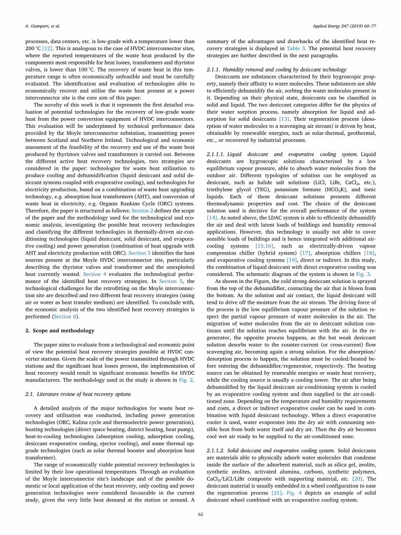
• Both technologies are able to remove moisture from the air moreefficiently than electrically-driven vapour compression system,where humidity is removed by cooling the air to the dew-point,overcooling of the air below dew-point and moisture removal forcondensation, and reheating to the required conditions of air for thebuilding. This process is highly inefficient from an energetic point ofview and results costly for applications where humidity control isperformed, as in thyristor valves hall where it is kept under controlto avoid condensation on the valves and limit corona discharge.Fig. 13 compares the two processes on a psychometric chart. Thefigure was obtained considering as outdoor air condition theaverage temperature and humidity at Moyle in July 2018(T=13.9 °C, RH=82%).
The air dehumidification process with solid desiccant results inproducing overheated dry air, which must be cooled before supplying itto the conditioned air zone. Under proper operation, liquid desiccantair-conditioning systems are able to simultaneously dehumidify andcool the air [16]. From an energetic point of view, liquid desiccant ishence the best choice for humidity control.
• The temperature required by the liquid desiccant regenerationprocess is lower than solid desiccant. Depending on ambient outdoorair conditions and desiccant solution, liquid desiccants require aregeneration temperature in the range 40–70 °C, while the tem-perature required for regeneration is in the range 60–115 °C for asolid desiccant as silica gel [46]. The waste heat present at theHVDC converter station might not be enough to drive the re-generation of a solid desiccant system.
• The structure of the solid desiccant systems is simpler, but theirability to hold moisture is lower [46]. The materials used as soliddesiccant are cheaper than liquid desiccant solutions [47].
• Any possible entrainment of liquid desiccant droplets in the airsupplied to the building must be strictly avoided for health andsafety reasons [48]. Carryover of the desiccant solution is one of themain drawbacks of LDAC systems. Common desiccants systemsemploy a demister after the dehumidifier to stop any possible en-trainment of liquid desiccant droplets in the air supplied to theconditioned zone. This technological solution results in an increasein the cost of the system and of its maintenance cost and in higherelectricity consumption to blow the air through the system [48].
Fig. 12. Ambient air, inlet and outlet cooling water temperature for Pole 1 and Pole 2 in 2009.
Table 6Measured data and calculated waste heat from the thyristor valves coolingsystem.
2009 Pole 1 2009 Pole 2 2014 Pole 1
Ambienttemperature (°C)
−3.6∼ 33.2;Average: 11.6
−3.4∼ 32.3;Average: 12.1
−1.1∼ 34.8;Average: 10.9
Coolant inlettemperature (°C)
Average: 40.1 Average: 39.5Max: 41.8
Average: 40.3Max: 42.5
Coolant outlettemperature (°C)
Average: 43.4 Average: 42.8Max: 45.9
Average: 44.1Max: 47.1
Temperaturedifference (°C)
2∼ 5.6Average: 3.33
0∼ 5.4Average: 3.3
1.4∼ 5.7Average: 3.8
Power (MW) −80∼ 250Average: 120
14∼ 242Average: 151
−245∼ 250Average: 146
Average waste heat(kW)
385 385 (268 wholeyear)
443a
a Temperature sensor failed in October.
Table 7Efficiencies and losses of transformers in different scales [45].
Transformer type Rated Power (MVA) Efficiency (%) at Loss (kW) at
100% Rated Load 50% Rated Load 100% Rated Load 50% Rated Load
Generator transformer 1100 99.60 99.75 4400 1375Interbus transformer 400 99.60 99.75 1600 500Substation transformer 40 99.40 99.60 240 80Distribution transformer 1 98.60 99.00 14 5
Table 8Waste heat from the transformer. Calculation based on 0.25% heat generation.
2009 Pole 1 2009 Pole 2 2014 Pole 1
Power (MW) −80∼ 205Average: 120
14∼ 242Average:151(108 whole year)
−245∼ 250Average: 146(120 whole year)
Waste heat (kW) 300 378 (270 whole year) 365a
Temperature (°C) 55–85 °Cb
a Temperature sensor failed in October.b Valid for all the conditions.
A. Giampieri, et al. Applied Energy 247 (2019) 60–77
68
More recently, an alternative solution has been the development ofindirect contact liquid desiccant system, involving the use of amembrane contactor between air and solution [49].
• The COP of solid desiccant systems is estimated to be around 0.4,while the COP of liquid desiccant air-conditioning systems can reacha value of approximately 0.8 [50] As reported by [51], the COP ofthe liquid desiccant air conditioning system can be slightly in-creased by reducing the parasitic losses.
• Unlike solid desiccant technology, liquid desiccant technology offersthe opportunity to store the waste heat in thermo-chemical form.This thermo-chemical energy can be stored almost free-losses andexploited when cooling is needed [52].
• Given the open-system characteristic of liquid desiccant systems,dehumidification and regenerator of the system can be split [53].The flexibility of liquid desiccant allows locating the regeneratorand the dehumidifier where the heat sources are present and wherethe cooling and dehumidification effect is needed, respectively [54].
• The dehumidification process with liquid desiccant technology is a“dry” process, not involving the use of fan coils, which wet surfacesare possible breeding sites of bacteria, moulds, E-coli, etc. [14]. Inaddition, desiccant solutions, particularly halide salt solutions suchas LiCl and LiBr, are able to remove, filter, or kill bacteria and virus[55]. Particularly important for HVDC stations is the ability of liquiddesiccant technology to filter dust [56] which results in increasedcorona discharge effect and higher electric losses and must be keptunder control.
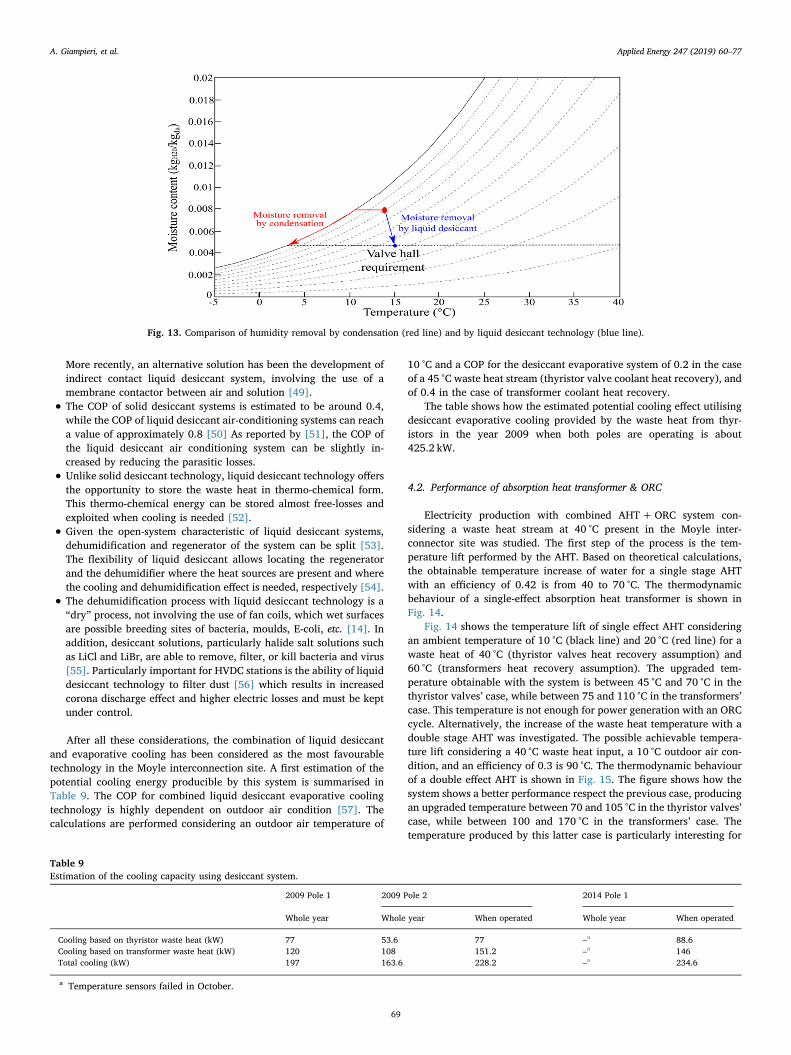
After all these considerations, the combination of liquid desiccantand evaporative cooling has been considered as the most favourabletechnology in the Moyle interconnection site. A first estimation of thepotential cooling energy producible by this system is summarised inTable 9. The COP for combined liquid desiccant evaporative coolingtechnology is highly dependent on outdoor air condition [57]. Thecalculations are performed considering an outdoor air temperature of
10 °C and a COP for the desiccant evaporative system of 0.2 in the caseof a 45 °C waste heat stream (thyristor valve coolant heat recovery), andof 0.4 in the case of transformer coolant heat recovery.
The table shows how the estimated potential cooling effect utilisingdesiccant evaporative cooling provided by the waste heat from thyr-istors in the year 2009 when both poles are operating is about425.2 kW.
4.2. Performance of absorption heat transformer & ORC
Electricity production with combined AHT+ORC system con-sidering a waste heat stream at 40 °C present in the Moyle inter-connector site was studied. The first step of the process is the tem-perature lift performed by the AHT. Based on theoretical calculations,the obtainable temperature increase of water for a single stage AHTwith an efficiency of 0.42 is from 40 to 70 °C. The thermodynamicbehaviour of a single-effect absorption heat transformer is shown inFig. 14.
Fig. 14 shows the temperature lift of single effect AHT consideringan ambient temperature of 10 °C (black line) and 20 °C (red line) for awaste heat of 40 °C (thyristor valves heat recovery assumption) and60 °C (transformers heat recovery assumption). The upgraded tem-perature obtainable with the system is between 45 °C and 70 °C in thethyristor valves’ case, while between 75 and 110 °C in the transformers’case. This temperature is not enough for power generation with an ORCcycle. Alternatively, the increase of the waste heat temperature with adouble stage AHT was investigated. The possible achievable tempera-ture lift considering a 40 °C waste heat input, a 10 °C outdoor air con-dition, and an efficiency of 0.3 is 90 °C. The thermodynamic behaviourof a double effect AHT is shown in Fig. 15. The figure shows how thesystem shows a better performance respect the previous case, producingan upgraded temperature between 70 and 105 °C in the thyristor valves’case, while between 100 and 170 °C in the transformers’ case. Thetemperature produced by this latter case is particularly interesting for
Fig. 13. Comparison of humidity removal by condensation (red line) and by liquid desiccant technology (blue line).
Table 9Estimation of the cooling capacity using desiccant system.
2009 Pole 1 2009 Pole 2 2014 Pole 1
Whole year Whole year When operated Whole year When operated
Cooling based on thyristor waste heat (kW) 77 53.6 77 –a 88.6Cooling based on transformer waste heat (kW) 120 108 151.2 –a 146Total cooling (kW) 197 163.6 228.2 –a 234.6
a Temperature sensors failed in October.
A. Giampieri, et al. Applied Energy 247 (2019) 60–77
69

combination with the ORC system.Considering a 5% efficiency for a small-scale ORC [58], the con-
version efficiency of the whole composed system for the recovery of a40 °C waste heat source and electricity production is 1.5%. Only about18.35 kW electricity can be generated by this combined AHT+ORCsystem using the waste heat present in the year of 2009 with both polesoperating. Table 10 summarises the estimated power producible by thesystem.
5. Retrofitting challenges
Once described the potential heat recovery strategies at Moyle in-terconnector and their performance, an evaluation of the best fluidemployable as heat recovery and transfer medium (water or air) and ofthe possible retrofitting challenges on-site was performed.
5.1. Heat transfer medium
For both the heat recovery strategies, hot water can be used as dueto low waste heat temperature (< 100 °C). The best retrofit strategy toobtain hot water from both thyristor cooling system and transformercooling system is to install a liquid-to-liquid heat exchanger, e.g. a plateheat exchanger, at the upstream of an air-to-water heat exchanger inthyristor valves’ cooling system and at the upstream of the oil-to-airradiator in transformer cooling system, respectively. The produced hotwater can be pumped elsewhere to drive the desiccant evaporativecooling or the AHT+ORC system. Alternatively, the direct use of thehot air from the waste heat system is a viable alternative option to theuse of hot water since the system naturally requires hot/warm air forthe desiccant system. This solution avoids the cost for the plate heatexchanger because warm air is already available. For the liquid de-siccant system, two heat recovery strategies can be performed with hot
air as illustrated by Fig. 16. The hot air produced by the air-to-waterheat exchanger can be collected at either downstream or upstream ofthe fan.
The flexibility of liquid desiccant systems, namely their ability toindistinctly drive their regeneration cycle with hot air or water, widensthe heat recovery feasibility with this technology for both retrofittingand new projects. The effect of the regeneration mode (air-heated orsolution-heated) on the performance of the liquid desiccant air-con-ditioning system is reported by [59]. On the other hand, for solid de-siccant systems, the situation is not as flexible as a liquid system sincethe regeneration and dehumidification occur in the same rotatingwheel, therefore only collecting hot air downstream of the fan is pos-sible for the solid desiccant system.
5.2. Thyristor valves’ coolant heat recovery
The heat content of the hot air/hot water produced by the thyristorvalve radiator may not be enough to drive the desiccant regeneration.Different solutions are used in desiccant systems, such as LiCl, LiBr,CaCl2, HCO2K, each with a different thermodynamics behaviour, re-sulting in different regeneration temperature among them. Fig. 17shows the desorption behaviour of different desiccant solutions on apsychometric chart. The thermodynamic properties of desiccant solu-tions were obtained from [60–62].
The figure was obtained considering the equilibrium vapour pres-sure of four desiccant solutions with concentration typical for re-generation process, namely CaCl2 solution (green line) 38% wt., HCO2K(red line) 70% wt., LiCl (blue line) 38% wt., and LiBr (magenta line)62% wt. and a regeneration efficiency of 0.7 [63]. The regenerationefficiency of a liquid desiccant system is defined as [64]:
Fig. 14. P-T diagram of single effect absorption heat transformer (left) and achievable temperature lift (right).
Fig. 15. P-T diagram of double effect absorption heat transformer (left) and achievable temperature lift (right).
A. Giampieri, et al. Applied Energy 247 (2019) 60–77
70

=−
−ε
ω ωω ωreg
air out air in
eq sol air in
, ,
, , (7)
where ωair out, and ωair in, represent the moisture content (kg dry air/kgH2O) of the air outlet and inlet the regenerator shown in Fig. 11, whileωeq sol, is the equilibrium moisture content of the desiccant solution en-tering the regenerator. The driving force of the moisture desorption(regeneration) process is the difference in the moisture content betweenthe desiccant solution and the outdoor air, i.e. the higher the difference,the easier the regeneration process. Under the considered outdoorconditions, the figure shows how CaCl2 is the only solution able todesorb its moisture content in the temperature range between 40 and45 °C. HCO2K and LiCl solutions present ability to desorb moisture butrequire a higher temperature for an efficient desorption process. LiBrsolution cannot be regenerated with the thyristor valves’ waste heat.Further experimental analysis must be conducted to prove the feasi-bility of CaCl2 liquid desiccant system driven by thyristor valves’ wasteheat.
5.3. Transformer’s coolant heat recovery
The higher temperature of the transformer’s coolant oil (between 55and 85 °C) is appropriate to drive the desiccant regeneration process. InHVDC converter stations, transformers are usually located next to thethyristor valves hall with the valves connected to the transformersthrough wall bushings [64]. Given the position of transformers andthyristor valve hall in the HVDC converter station, the identified heatrecovery strategy is to utilise the transformer waste heat to dehumidifyand cool the valve hall supply air with desiccant technology. The dis-position of transformers and thyristor valves hall is depicted in Fig. 18.
6. Economic analysis
6.1. Heat recovery for electricity production
To evaluate the economic factors involved in the electricity pro-duction process, a literature review of the of AHT and ORC systems wasperformed. The economic analysis of AHTs was obtained consideringthe investment costs of comparable absorption chillers, considering the
Table 10Power generation using the combined system of AHT and ORC.
2009 Pole 1 2009 Pole 2 2014 Pole 1
Whole year Whole year When operated Whole year When operated
Power based on thyristor waste heat (kW) 5.78 4.02 5.8 – 6.65Power based on transformer waste heat (kW) 4.5 4.05 5.67 – 5.48Total power (kW) 10.28 8.07 11.47 – 12.13
Fig. 16. Air as waste heat recovery medium, used at the downstream (left) and at the upstream of the fan (right).
Fig. 17. Desorption ability of desiccant solution under Northern Ireland summer conditions.
A. Giampieri, et al. Applied Energy 247 (2019) 60–77
71

lack of data on this new technology. A specific cost (SC) function fordouble effect AHT was regressed from [67]:
= − ∗ +SC Cooling capacity51.22 log( ) 538.3 (8)
Fig. 19 shows the specific cost function depending on the coolingcapacity for double effect absorption chiller. Considering an efficiencyof 30%, the capacity of AHT for waste heat from thyristor valves only is196 kW and is 367 kW for waste heat produced from both thyristorvalves and transformer. As calculated from the previous equation, thecapital cost of a double effect absorption chiller would be 52,520 € (forthyristor valves heat recovery) and 86,550 € (thyristor valves and
transformers heat recovery).Fig. 20 shows the specific cost function depending on the nominal
output power of the ORC system [68]. As in the previous case, the lit-erature review showed how lower size ORC systems present higherequipment cost. In the present study, a cost of 7 k€/kW was consideredfor a 9.8 kW ORC system, while 5.5 k€/kW is used for an 18.4 kW ORCsystem [68].
The results of the economic analysis of the heat upgrade and elec-tricity production process at the Moyle interconnector are shown inTable 11. Some additional assumptions were used in the economicanalysis:
Fig. 18. Vertical (left) and lateral (right) view of transformer and thyristor valve hall of HVDC converter station, adapted from [33,65,66].
Fig. 19. Specific cost function depending on the cooling capacity of double effect absorption chiller.
Fig. 20. Specific cost function depending on nominal output power of ORC system, .adapted from [68]
A. Giampieri, et al. Applied Energy 247 (2019) 60–77
72

1. The setup costs are included in the capital cost of the combinedsystem;
2. The yearly maintenance cost for the AHT is 5% of the capital cost ofthe system [69];
3. The operational cost for the AHT is obtained by the manufacturermanual [67];
4. The operation and maintenance (O&M) costs for ORC are 0.03 €/kWh [70];
5. The electricity cost is 0.1 €/kWh.
The table shows how the low electricity production (and relatedeconomic earning) together with the high capital cost does not produceremarkable economic savings for the studied combined heat recoverystrategy, presenting not feasible payback period (higher than 50 years).The low-temperature waste heat and the current capital costs of AHTand ORC technologies limit the realisation of heat-to-electricity re-covery technology at the Moyle interconnection station and in generalin HVDC stations.
6.2. Heat recovery for dehumidification and cooling
6.2.1. Liquid desiccant capital cost evaluationFor the evaluation of the capital cost of a liquid desiccant system, a
literature review was conducted [71–75]. One of the main problems forthe evaluation of the capital cost of liquid desiccant systems is the lackof available data and the difference in the system configuration be-tween the various references.
Being the liquid desiccant an open system technology which per-formance is highly dependent on the outdoor air condition, the char-acterisation of the cost function depending on the cooling effect isunreliable. A better strategy for the characterisation of the specific costfunction of a liquid desiccant system is to evaluate its proportionalitywith respect to the air volume flow rate of the machine. A specific costfunction depending on the volume flow rate was regressed to by theliterature review. However, the cost function obtained for the liquiddesiccant systems shows an unreliable behaviour for some cases. Thisdifference is mainly due to the difference in the LD system cost betweenmanufacturing cost, local distributor overhead costs, and end-users costand on the typology of the liquid desiccant system employed (LDACstandalone system, internally-cooled system, etc.). For this reason andgeneral consistency, a regression model for the specific cost function ofthe Kathabar liquid desiccant system was obtained and is shown inFig. 21 [76]. The regressed specific cost function is:
= − ∗ +SC Volume flow rate7.9319 ( ) 24.6067(0.0877) (9)
Considering as Ref. [36] for the ventilation air requirement of athyristor valve hall of a 500MW HVDC converter station, the Moyle’sthyristor valves hall (250MW each pole) requires 12,610m3/h of
ventilation air. Using (9), the estimated capital cost of the required li-quid desiccant system would be 81,350 €.
6.2.2. ResultsAn economic evaluation of economic savings achievable with liquid
desiccant technology was performed. As in the previous case, someassumptions have been utilised for the economic analysis and are heresummarised:
The setup costs are included in the capital cost of the desiccantcooling system;The yearly maintenance cost of the combined liquid desiccantsystem is 2% of the capital cost [77], while the yearly maintenancecost of the vapour-compression electrical chiller is 3% of the capitalcost [78];The yearly operation cost of the desiccant system is 5% of the capitalcost [77];Temperature and humidity control in the valve hall is performed allthe year-round to ensure proper operation of the thyristor valves;The COP of the electrically-driven refrigerator is 3;The electricity cost is 0.10 €/kWh.
Outdoor air condition data (temperature and relative humidity) ofLarne, Northern Ireland (close to Ballycronan More), were collected ona three-hour basis in the period August 2017-July 2018 [79] and usedin the analysis. The yearly outdoor air condition together with the valvehall’s air requirement are displayed in Fig. 22.
The figure shows how the moisture content of outdoor air during theyear is most of the times higher than the value required by the thyristorvalves hall (T=15 °C, RH=45%). For this reason, economic benefitsare achievable with the proposed heat recovery strategy, able to effi-ciently control the moisture with the desiccant technology. During thecolder months (November to April), the moisture content in the outdoorair is generally lower than thyristor valves hall requirement, i.e. littleeconomic savings are possible. In the rest of the months (May toOctober), economic savings are achievable and are shown in Fig. 23.Possible additional sensible cooling (vapour compression or evapora-tive) may be needed in the hottest days of summer.
The calculated yearly savings in the considered period are13,725.93 €. The results of the economic analysis showing paybackperiod and LCOSE are presented in Table 12. The table shows how thepayback period (8.7 years) and LCOSE (0.305 €/kWh) is high for theretrofit of the air-conditioning system of the thyristor valves hall, wheretwo refrigerators (74 kW) are already installed.
However, in a new HVDC converter station employing liquid de-siccant technology for the air conditioning system of thyristor valveshall much better economic performance would be achievable, underclimatic conditions like those of Moyle. Given the ability of the tech-nology in dealing with latent loads, the sensible cooling needed wouldbe sensibly reduced. For this reason, in the design of a new HVDCconverter station the size of the refrigeration system would be sig-nificantly reduced. Considering a new HVDC project two strategieswere identified for the dehumidification and cooling:
• Combined liquid desiccant (LD) and vapour compression (VC)system. In Moyle, the liquid desiccant technology could be used toremove latent loads while one refrigerator (50 kW) is used as backupand to remove sensible loads during the hottest days of summer,instead of using 2*74 kW refrigerators. In this case, the savings inthe capital cost for the vapour-compression cooling system would beabout 29,400 €, considering a specific cost of 300 €/kW for thesystem [54]. For this new HVDC project, the economic performanceof the heat recovery process increases, resulting in a payback periodof 6.1 years and an LCOSE of 0.2 €/kWh. This solution would pre-sent both technologically and economic feasibility, considering thelifespan of the technology.
Table 11Costs and payback period of AHT+ORC system.
Case 1 Case 2
Waste heat (kW) 653 1223Efficiency (–) 0.3 0.3AHT power (kW) 196 367ORC power (kW) 9.8 18.35Earnings (€/year) 8548 16,074.6AHT capital cost (€) 52,520 86,550ORC capital cost (€) 68,600 101,200Total capital cost (€) 121,120 187,750AHT maintenance cost (€/year) 2626 4327.5AHT electricity cost (€/year) 1489.2 3679.2O&M ORC cost (€/year) 2575.44 4822.38Total operation cost (€/year) 6690.64 12,829.08Savings (€/year) 1857.36 3245.52Payback period (year) – –
A. Giampieri, et al. Applied Energy 247 (2019) 60–77
73

• Combined liquid desiccant and direct evaporative cooling (DEC)system. In this case, the sensible heat removal would be performedby the direct evaporative system, resulting in higher economicsavings respect the previous case. In this case, the savings in thecapital cost for the vapour-compression cooling system would beabout 44,400 €. The capital cost of a direct evaporative coolingsystem able to sensibly cool the thyristor valves hall would be2470 € [80]. This heat recovery strategy results in being the mostbeneficial in terms of savings and environment, showing a paybackperiod of 5 years and an LCOSE of 0.155 €/kWh. However, thetechnological feasibility of this combined system must be proved inhot and humid climates, given the sensible cooling removal abilityof the technology and the importance of temperature and humiditycontrol in HVDC stations.
The values obtained for the LCOSE are high, particularly for theretrofitting. As a comparison, a techno-economic analysis for geo-thermal heat recovery and cooling with absorption chiller technology[32] showed an LCOSE ranging between 0.1 and 0.16 €/kWh, de-pending on the climatic condition. Given the lifespan of the combineddesiccant evaporative technology and its high electricity consumptionreduction, this technology emerges as the most promising from anLCOSE analysis point of view.
One of the main advantages of the liquid desiccant technology
respect its competitor solid is the potential ability to dehumidify andcool, depending on the outdoor air conditions [38]. Considering theoutdoor air conditions on the psychometric chart shown in Fig. 22, thelow temperature at Moyle interconnector causes sensible cooling to beonly necessary on the hottest days of summer. As previously said, thisoperation can be performed by vapour compression or evaporativecooling system. The costs associated with sensible cooling would bevery low for these combined technologies, given the low temperatureand high humidity of the ambient air at the Moyle HVDC station, andthe ability of the liquid desiccant technology to remove the latter.
7. Summary and conclusion
Technological and economic evaluation of the heat recovery of thelow-grade waste heat sources present in the Moyle high-voltage directcurrent (HVDC) interconnector connecting Scotland and NorthernIreland was conducted. Given the worldwide increase of HVDC tech-nology use for long-distance transport of electricity, the identificationof heat recovery as a technologically and economically viable solutionfor HVDC interconnectors would result in significant environmentaland economic benefits.
The data collection and quantification of the available heat at theMoyle interconnector station showed that: (1) 653 kW are availablefrom the thyristor valves’ cooling fluid at 43–45 °C, (2) 570 kW are from
Fig. 21. Specific cost per air volume flow rate of Kathabar LD system.
Fig. 22. Yearly outdoor air condition Larne, Northern Ireland.
A. Giampieri, et al. Applied Energy 247 (2019) 60–77
74

the transformer’s cooling fluid at 55–85 °C. Amongst evaluated heatrecovery technologies for domestic or commercial local application,two heat recovery have been considered as interesting for HVDC in-terconnectors. The first one is the utilisation of the waste heat for de-humidification and cooling effect, with a combination of desiccant andcooling system (electric or evaporative). Alternatively, the possibleproduction of electricity with Organic Rankine cycle (ORC) driven bylow-temperature waste heat was evaluated. Absorption heat transfor-mers are used to provide the heat required by ORC cycle. From thestudy, the following conclusions were obtained:
1. Production of electricity with Moyle HDVC interconnection station’swaste heat is technologically but not economically feasible, giventhe current high capital cost and low efficiency of the systems.
2. Combined desiccant and evaporative cooling was considered themost promising technology. Given the importance of temperatureand humidity control in the thyristor valves hall to ensure properoperation, economic savings are achievable with liquid desiccanttechnology, able to efficiently remove moisture and being driven bythe waste heat sources present at the converter station.
3. The temperature of the low-grade waste heat is one of the mainconstraints influencing the efficiency and economic feasibility of theheat recovery project. The temperature of the heat recovered by thethyristor valves hall’s cooling fluid may not be enough to drive theregeneration process of a desiccant system. Desiccant solutionscharacterised by a lower regeneration temperature, such as CalciumChloride (CaCl2), may be able to be regenerated by the heat contentpresent. The transformer’s cooling fluid heat recovery to drive liquiddesiccant technology is considered a feasible strategy.
4. Retrofitting the Moyle converter station with liquid desiccant wouldpresent a high payback period (8.7 years) and levelised cost of savedenergy (LCOSE) of 0.305 €//kWh. Better economic performancesare obtained for a heat recovery project in a new design HVDC site.A combination of liquid desiccant and vapour compression coolingshowed a payback period is 6.1 years and an LCOSE of 0.2 €//kWh.The best performing technological solution from an economic andenvironmental point of view is the combined desiccant and eva-porative cooling system, presenting a payback period of 5 years andan LCOSE of 0.155 €//kWh. This value is comparable to other heatrecovery projects.
The analysis has shown that the economic benefits resulting fromthe heat recovery process are strongly influenced by several parametersin HVDC interconnectors, such as system size, thyristor valves andtransformers’ cooling fluid temperature, outdoor air conditions (tem-perature and humidity), etc. Heat-to-dehumidification/cooling hasbeen proved as the best heat recovery option for the Moyle inter-connection station. Next steps of the research should evaluate the po-tential of combined desiccant and evaporative cooling in HVDC stationslocated in hot and humid climates where the humidity removal abilityof the technology would result in higher economic savings.
Acknowledgments
The authors gratefully acknowledge the support from theDemonstrating industrial opportunities in waste heat recovery project(EP/K503885/1) funded by Engineering and Physical SciencesResearch Council (EPSRC), the Heat-STRESS project (EP/N02155X/1)funded by the Engineering and Physical Science Research Council(EPSRC), and the H-DisNet project funded by European Union‘s Horizon2020 research and innovation Programme under grant agreement695780.
Data supporting this publication is openly available under an ‘OpenData Commons Open Database License’. Additional metadata areavailable at: http://dx.doi.org/10.17634/160152-1.
References
[1] Baker C. HVDC transmission and interconnectors. Available from: <https://energyhub.theiet.org/users/63044-carl-barker/posts/20073-hvdc-transmission-and-interconnectors> [accessed 08/12/2017].
[2] Berg JR, Soliman HM, Ormiston SJ. Effective cooling of stacked heat-generatingbodies in a large room: comparison between floor and side-wall air injection. Int J
Fig. 23. Monthly economic savings (€) with liquid desiccant technology.
Table 12Economic analysis of the heat recovery with desiccant system.
Retrofit New project 1 New project 2
Flow rate (m3/h) 12,610 12,610 12,610LD capital cost (€) 81,350 81,350 81,350DEC capital cost (€) / / 2470VC capital cost savings (€) / 29,400 44,400Maintenance cost LD (€/year) 1627 1627 1676.4Maintenance cost VC (€/year) 1332 432 /Operation cost (€/year) 4067.45 4067.45 4191Savings (€/year) 13,725.93 13,725.93 13,725.93Payback period (years) 8.7 6.1 5LCOSE (€/kWh) 0.305 0.2 0.155
A. Giampieri, et al. Applied Energy 247 (2019) 60–77
75

Therm Sci 2008;47(6):787–99.[3] Cost and benefits of GB interconnection. A Poyry report to the National
Infrastructure Commission. February 2016. Available from: <https://www.nic.org.uk/wp-content/uploads/Costs-and-benefits-of-GB-Interconnection-A-Poyry-Report.pdf> [accessed 12/11/17].
[4] HVDC projects. Available from: <https://en.wikipedia.org/wiki/List_of_HVDC_projects> [accessed 12/11/2017].
[5] HVDC Projects Listing. IEEE HVDC and FACTS Subcommittee. Available from:<http://www.ece.uidaho.edu/hvdcfacts/Projects/HVDCProjectsListingMarch2012-existing.pdf> [accessed 12/11/17].
[6] Presidency Conclusions. Barcelona European Council, 2002. Available from:<http://ec.europa.eu/invest-in-research/pdf/download_en/barcelona_european_council.pdf> [accessed 12/11/17].
[7] Bayliss CR, Hardy BJ. Transmission and distribution electrical engineering. 4th ed.Elsevier Ltd.; 2011.
[8] Astrom U, Lescale V. Converter Stations for 800 kV HVDC. International Conferenceon Power System Technology.
[9] Ammar Y, Joyce S, Norman S, Wang Y, Roskilly AP. Low grade thermal energysources and uses from the process industry in the UK. Appl Energy 2012;89:3–20.
[10] Chan CW, Ling-Chin J, Roskilly AP. A review of chemical heat pumps, thermo-dynamic cycles and thermal energy storage technologies for low grade heat utili-zation. Appl Therm Eng 2013;50:1257–73.
[11] Reay DA, Morrell M. Overview of process heat recovery. Presentation to the HeatExchanger Action Group (HEXAG): Carbon Trust; 2007.
[12] Fang H, Xia J, Zhu K, Su Y, Jiang Y. Industrial waste heat utilization for low tem-perature district heating. Energy policy 2013;62:236–46.
[13] ASHRAE. Handbook of Fundamentals. American Society of Heating, Refrigeratingand Air-conditioning Engineers, Atlanta; 2005 [chapter 22].
[14] Giampieri A, Ma Z, Smallbone A, Roskilly A. Thermodynamics and economics ofliquid desiccants for heating, ventilation, and air-conditioning. Appl Energy2018;220:455–79.
[15] Mujahid Rafique M, Gandhidasan P, Bahaidarah HMS. Liquid desiccant materialsand dehumidifiers – a review. Renew Sustain Energy Rev 2016;56:179–95.
[16] Abdel-Salam AH, Simonson CJ. State-of-the-art in liquid desiccant air conditioningequipment and systems. Renew Sustain Energy Rev 2016;56:179–95.
[17] Dai YJ, Wang RZ, Zhang HF, Yu JD. Use of liquid desiccant cooling to improve theperformance of vapor compression air conditioning. Appl Therm Eng2001;21:1185–202.
[18] Ko SM. LiCl dehumidifier/LiBr absorption chiller hybrid air conditioning systemwith energy recovery. Patent US4205529; 1980.
[19] Buker MS, Riffat SB. Recent developments in solar assisted liquid desiccant eva-porative cooling technology – a review. Energy Build 2015;96:95–108.
[20] Jani DB, Mishra M, Sahoo PK. Solid desiccant air conditioning – a state of the artreview. Renew Sustain Energy Rev 2016;60:1451–69.
[21] Sahlot M, Riffat SB. Desiccant cooling systems: a review. Int J Low-Carbon Technol2016:1–17.
[22] Little AB, Garimella S. Comparative assessment of alternative cycles for waste heatrecovery and upgrade. Energy 2011;36:4492–504.
[23] Kurem E, Horuz I. A comparison between ammonia–water and water–lithiumbromide solutions in absorption heat transformers. Int Commun Heat Mass Transf2001;28:427–38.
[24] Horuz I, Kurt B. Single stage and double absorption heat transformers in an in-dustrial application. Int J Energy Res 2009;33:787–98.
[25] Ma Z, Bao H, Roskilly AP. Performance analysis of ultralow grade waste heat up-grade using absorption heat transformer. Appl Therm Eng 2016;101:350–61.
[26] Wang L, Li H, Bu X, Wang H, Ma W. Performance study of a double absorption heattransformer. Energy Procedia 2017;105:1473–82.
[27] Broberg Viklund S, Johansson MT. Technologies for utilization of industrial wasteheat: Potentials for energy recovery and CO2 emission reduction. Energy ConversManage 2014;77:369–79.
[28] Haddad C, Perillon C, Danlos A, Francois MX, Descombes G. Some efficient solu-tions to recover low and medium waste heat: competitiveness of the thermoacoustictechnology. Energy Procedia 2014;40:1056–69.
[29] Lecompte S, Huisseune H, van den Broek M, Vanslambrouck B, De Paepe M. Reviewof organic Rankine cycle (ORC) architectures for waste heat recovery. RenewSustain Energy Rev 2015;47:448–61.
[30] Tchanche BF, Lambrinos G, Frangoudakis A, Papadakis G. Low-grade heat con-version into power using organic Rankine cycles – a review of various applications.Renew Sustain Energy Rev 2011;15:3963–79.
[31] Chaiyat N. Upgrading of low temperature heat with absorption heat transformer forgenerating electricity by organic rankine cycle. Glob Adv Res J Eng Technol Innov2014;3(9):235–47.
[32] Liu X, Yang Z, Gluesenkamp KR, Momen AM. A technical and economic analysis ofan innovative two-step absorption system for utilizing low-temperature geothermalresources to condition commercial buildings. PROCEEDINGS, 41st workshop ongeothermal reservoir engineering Stanford University, Stanford, California,February 22–24. 2016.
[33] High Voltage Direct Current Transmission – Proven Technology for PowerExchange. Available from: http://www.siemens.com/energy/hvdc [accessed 13/12/17].
[34] Standard: IEC 61803 ed.1.1. Determination of power losses in high-voltage directcurrent (HVDC) converter stations with line-commutated converters. Standard;2016.
[35] ALSTOM. HVDC for beginners and beyond. Available from: <http://cigre.ru/research_commitets/ik_rus/b4_rus/library/ALSTOM_HVDC_for_Beginners_and_Beyond.pdf> [accessed 30/07/2018].
[36] Lozowy RJ, El-Shaboury AM, Soliman HM, Ormiston RJ. Simulation and perfor-mance enhacement of the air cooling system in the valve halls of a DC/AC powerconverter station. Build Simul 2010;3:233–44.
[37] Sharifabadi K, Harnefors L, Nee HP, Norrga S, Teodorescu R. Design, control, andapplication of modular multilevel converters for HVDC transmission systems.Wiley; 2016.
[38] Zhang X, Bian X, Cui X, Lu T, Li H, Li Q, et al. Experimental investigation on hu-midity effects on the variations of positive DC Corona Discharge. IEEE internationalpower modulator and high voltage conference (IPMHVC). 2016.
[39] Byrne T. Humidity effects in substations. Petroleum and chemical industry con-ference Europe. 2014.
[40] Harriman III G. The dehumidification handbook. Munsters Corporation; 2002.[41] Hunt R, Giordano ML. Thermal overload protection of power transformers – oper-
ating theory and practical experience. 59th annual protective relaying conference,Atlanta, Georgia, April 27th – 29th. 2005.
[42] Perez J. Fundamental principles of transformer thermal loading and protection.63rd annual conference for protective Relay Engineers, TX, USA. 2010.
[43] Rodriguez LA, Padilla AA, Spake NB. Power transformer waste heat recoverysystem. Patent US 4512387 A; 1985.
[44] Chien ZJ, et al. A Study of waste-heat recovery unit for power transformer. AdvMater Res 2014;875–877:1661–5.
[45] Fassbinder S. Application note efficiency and loss evaluation of large powertransformers. European Copper Institute Copper Alliance and Leonardo Energy;2013.
[46] Katejanekam T, Kumar S. Performance of a solar-regenerated liquid desiccantventilation pre-conditioning system. Energy Build 2008;40(7):1252–67.
[47] Baniyounes AM, Ghadi YY, Rasul MG, et al. An overview of solar assisted air con-ditioning in Queensland’s subtropical regions, Australia. Renew Sustain Energy Rev2013;26:781–804.
[48] Lowenstein A. Review of liquid desiccant technology for HVAC applications. HVAC&R Res 2008;14(6):819–39.
[49] Ge G, Abdel-Salam AH, Besant RW, Simonson CJ. Research and applications of li-quid-to-air membrane energy exchangers in building HVAC systems at University ofSaskatchewan: a review. Renew Sustain Energy Rev 2013;26:464–79.
[50] Allouhi A, Kouksou T, Jamil A, Bruel P, Mourad Y, Zeraoluli Y. Solar driven coolingsystems: an update review. Renew Sustain Energy Rev 2015;44:159–81.
[51] Gommed K, Grossman G. Experimental investigation of a liquid desiccant system forsolar cooling and dehumidification. Sol Energy 2007;81:131–8.
[52] Geyer P, Buchholz M, Buchoolz R, Provost M. Hybrid thermo-chemical districtnetworks – principles and technology. Appl Energy 2017;186(3):480–91.
[53] Giampieri A, Buchholz M, Geyer P, Buchholz R, Engel C, Royapoor M, et al.Application cases and economic benefits of thermo-chemical networks. Conference:4th Sustainable Thermal Energy Management International Conference(SusTEM2017). Alkmaar, Netherlands. 2017.
[54] Geyer P, Delwati M, Buchholz M, Giampieri A, Smallbone A, Roskilly AP, et al. Usecases with economics and simulation for thermo-chemical district networks.Sustainability 2018;10(3):1–32. 599.
[55] Fu HX, Liu XH. Review of the impact of liquid desiccant dehumidification on indoorair quality. Build Environ 2017;116:158–72.
[56] Liu XH, Zhang WR, Li Z, Jiang Y. Independent humidity control air-conditioningsystem using liquid desiccant. Indoor Air Proceeding. 2005.
[57] Mujahid Rafique M, Rehman S, Alhems LM, Ali Shakir M. A liquid desiccant en-hanced two stage evaporative cooling system – development and performanceevaluation of a test rig. Energies 2018;11(1):72.
[58] Vankeirsbilck I, Vanslambrouck B, Gusev S, De Paepe M. Organic Rankine cycle asefficient alternative to steam cycle for small scale power generation. 8th interna-tional conference on heat transfer, fluid mechanics and thermodynamics, Mauritius11th–13th July. 2011.
[59] Liu XH, Jiang Y, Yi XQ. Effect of regeneration mode on the performance of liquiddesiccant packed bed regenerator. Renew Energy 2009;34(1):209–16.
[60] Conde-Petit M. Property of aqueous solutions of lithium and calcium chlorides:formulations for use in air condition equipment design. Int J Therm Sci2004;43:367–82.
[61] Patek J, Klomfar J. A computationally effective formulation of the thermodynamicproperties of LiBr-H2O solutions from 273 K to 500 K over full composition range.Int J Refrig 2006;29:566–78.
[62] Elmer T. A novel SOFC tri-generation system for building applications. Springer;2013.
[63] Martin V, Goswami Y. Effectiveness of heat and mass transfer processes in a packedbed liquid Desiccant Dehumidifier/Regenerator. HVAC&R Res 2000;6(1):21–39.
[64] Kabeel AE, Bassuoni MM. Theoretical performance study of a liquid desiccant re-generator supported with scavenging air heat exchanger. J Renew Sustain Energy2013;5.
[65] McDonald JD. Electric power substations engineering. CRC Press; 2012.[66] Sarkar J, Patil R. Detection of partial discharges occurring in HVDC environment.
Int J Innov Sci Eng Technol 2014;1(4):424–8.[67] BROAD X Absorption Chiller Model Selection & Design Manual. Available from:
<http://www.gqsltd.co.uk/BROAD%20X%20Absorption%20Chiller%20Model%20Selection%20%20Design%20Manual%20.pdf> [accessed 17/05/2018].
[68] Quoilin S, Broek MVD, Declaye S, Dewallef P, Lemort V. Techno-economic survey oforganic rankine cycle (ORC) system. Renew Sustain Energy Rev 2013;22:168–86.
[69] Best Practice Programme. An introduction to absorption cooling. Good PracticeGuide. Technical Report; 1999.
[70] Rossland K. Feasibility of using Rankine power cycle for utilisation of medium tolow temperature heat sources in the industry. Master Thesis of Energy andEnvironmental Engineering. Norwegian University of Science and Technology;
A. Giampieri, et al. Applied Energy 247 (2019) 60–77
76

2016.[71] Liu XH, Geng KC, Lin BR, Jiang Y. Combined cogeneration and liquid-desiccant
system applied in a demonstration building. Energy Build 2004;36:945–53.[72] Badami M, Portoraro A. Performance analysis of an innovative small-scale trigen-
eration plant with liquid desiccant cooling system. Energy Build2009;41:1195–204.
[73] Enquiry to Chinese desiccant cooling system producer; 2018.[74] Dean J, Kozubal E, Herrmann L, Miller J, Lowensteing A, Barker G, et al. Solar-
powered, liquid-desiccant air conditioner for low-electricity humidity control.NREL Technical Report; 2012.
[75] Miller JA, Lowenstein A. The field operation of a thermally driven liquid-desiccantair conditioner. AIL Research, Inc.; 2008.
[76] Energy and Environmental Analysis, Inc. Distributed Energy Technology
Characterization. US Department of Energy, Energy Efficiency and RenewableEnergy. Technical report; 2004.
[77] Ge TS, Ziegler F, Wang RZ, Wang H. Performance comparison between a solardriven rotary desiccant cooling system and conventional vapour compressionsystem (performance study of desiccant cooling). Appl Therm Eng 2010;30:724–31.
[78] Lim BBP. Solar energy applications in the tropics. Proceedings of a regional seminarand workshop on the utilization of solar energy in hot humid urban development.Singapore. 1980.
[79] Larne weather. Available from: <https://www.worldweatheronline.com/larne-weather-history/larne/gb.aspx> [accessed 17/10/18].
[80] Baakem SS, Orfi J, Bessadok-Jemai A. Thermodynamic and economic analysis of theperformance of a direct evaporative cooler working under extreme summer weatherconditions. J Mech Sci Technol 2018;32(4):1815–25.
A. Giampieri, et al. Applied Energy 247 (2019) 60–77
77