Technische Information / Technical Information IGBT ...
9
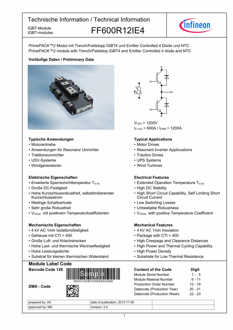
1 Technische Information / Technical Information FF600R12IE4 IGBT-Module IGBT-modules prepared by: AC approved by: MS date of publication: 2013-11-05 revision: 2.4 PrimePACK™2 Modul mit Trench/Feldstopp IGBT4 und Emitter Controlled 4 Diode und NTC PrimePACK™2 module with Trench/Fieldstop IGBT4 and Emitter Controlled 4 diode and NTC Vorläufige Daten / Preliminary Data VCES = 1200V IC nom = 600A / ICRM = 1200A Typische Anwendungen Typical Applications • • Motorantriebe Motor Drives • • Anwendungen für Resonanz Umrichter Resonant Inverter Appliccations • • Traktionsumrichter Traction Drives • • USV-Systeme UPS Systems • • Windgeneratoren Wind Turbines Elektrische Eigenschaften Electrical Features • • Erweiterte Sperrschichttemperatur Tvj op Extended Operation Temperature Tvj op • • Große DC-Festigkeit High DC Stability • • Hohe Kurzschlussrobustheit, selbstlimitierender Kurzschlussstrom High Short Circuit Capability, Self Limiting Short Circuit Current • • Niedrige Schaltverluste Low Switching Losses • • Sehr große Robustheit Unbeatable Robustness • • VCEsat mit positivem Temperaturkoeffizienten VCEsat with positive Temperature Coefficient Mechanische Eigenschaften Mechanical Features • • 4 kV AC 1min Isolationsfestigkeit 4 kV AC 1min Insulation • • Gehäuse mit CTI > 400 Package with CTI > 400 • • Große Luft- und Kriechstrecken High Creepage and Clearance Distances • • Hohe Last- und thermische Wechselfestigkeit High Power and Thermal Cycling Capability • • Hohe Leistungsdichte High Power Density • • Substrat für kleinen thermischen Widerstand Substrate for Low Thermal Resistance Module Label Code Barcode Code 128 DMX - Code Content of the Code Digit Module Serial Number 1- 5 Module Material Number 6 - 11 Production Order Number 12 - 19 Datecode (Production Year) 20 - 21 Datecode (Production Week) 22 - 23
Transcript of Technische Information / Technical Information IGBT ...
1
TechnischeInformation/TechnicalInformation
FF600R12IE4IGBT-ModuleIGBT-modules
preparedby:ACapprovedby:MS
dateofpublication:2013-11-05revision:2.4
PrimePACK™2ModulmitTrench/FeldstoppIGBT4undEmitterControlled4DiodeundNTCPrimePACK™2modulewithTrench/FieldstopIGBT4andEmitterControlled4diodeandNTC
VorläufigeDaten/PreliminaryData
VCES = 1200VIC nom = 600A / ICRM = 1200A
TypischeAnwendungen TypicalApplications• •Motorantriebe MotorDrives• •AnwendungenfürResonanzUmrichter ResonantInverterAppliccations• •Traktionsumrichter TractionDrives• •USV-Systeme UPSSystems• •Windgeneratoren WindTurbines
ElektrischeEigenschaften ElectricalFeatures• •ErweiterteSperrschichttemperaturTvjop ExtendedOperationTemperatureTvjop
• •GroßeDC-Festigkeit HighDCStability• •Hohe Kurzschlussrobustheit, selbstlimitierenderKurzschlussstrom
High Short Circuit Capability, Self Limiting ShortCircuitCurrent
• •NiedrigeSchaltverluste LowSwitchingLosses• •SehrgroßeRobustheit UnbeatableRobustness• •VCEsatmitpositivemTemperaturkoeffizienten VCEsatwithpositiveTemperatureCoefficient
MechanischeEigenschaften MechanicalFeatures• •4kVAC1minIsolationsfestigkeit 4kVAC1minInsulation• •GehäusemitCTI>400 PackagewithCTI>400• •GroßeLuft-undKriechstrecken HighCreepageandClearanceDistances• •HoheLast-undthermischeWechselfestigkeit HighPowerandThermalCyclingCapability• •HoheLeistungsdichte HighPowerDensity• •SubstratfürkleinenthermischenWiderstand SubstrateforLowThermalResistance
ModuleLabelCodeBarcodeCode128
DMX-Code
ContentoftheCode DigitModuleSerialNumber 1-5ModuleMaterialNumber 6-11ProductionOrderNumber 12-19Datecode(ProductionYear) 20-21Datecode(ProductionWeek) 22-23
2
TechnischeInformation/TechnicalInformation
FF600R12IE4IGBT-ModuleIGBT-modules
preparedby:ACapprovedby:MS
dateofpublication:2013-11-05revision:2.4
VorläufigeDatenPreliminaryData
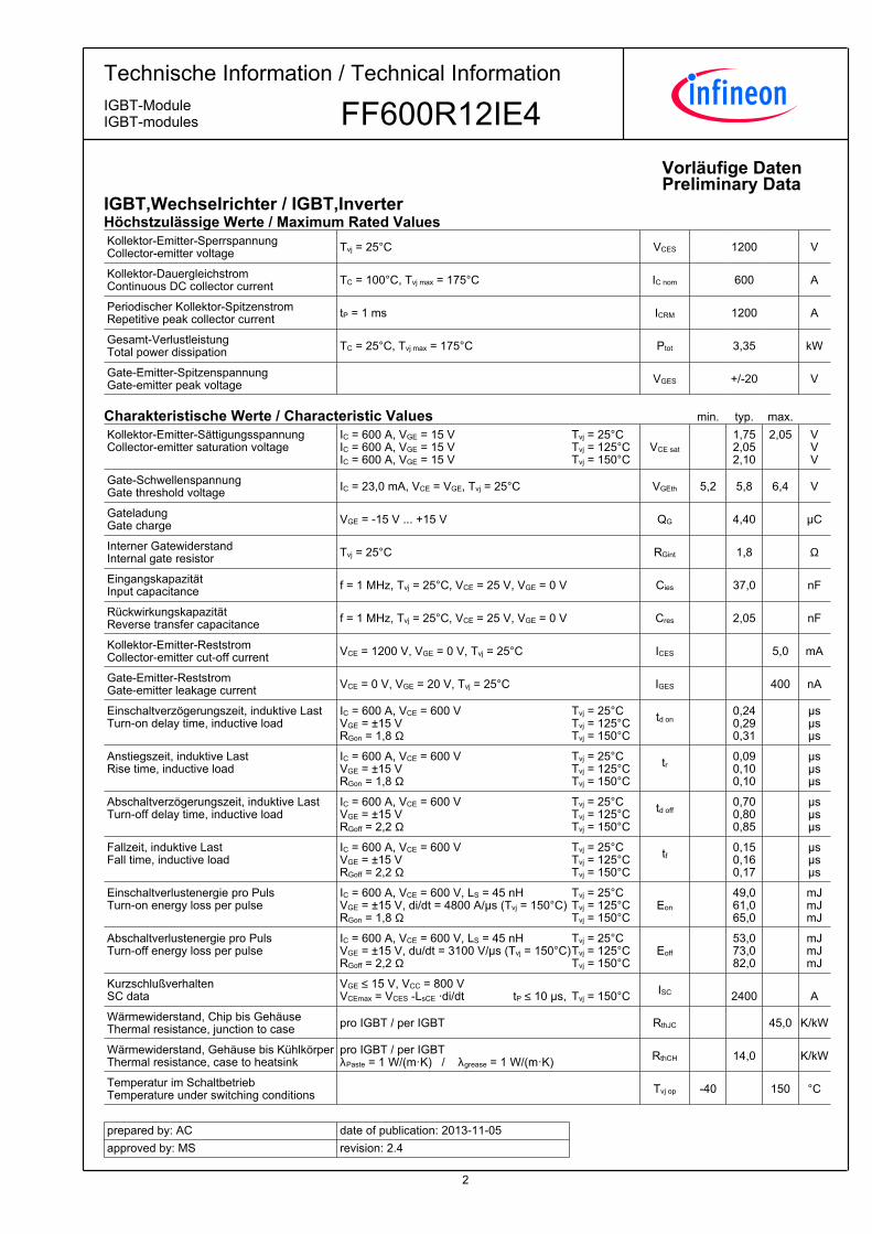
IGBT,Wechselrichter/IGBT,InverterHöchstzulässigeWerte/MaximumRatedValuesKollektor-Emitter-SperrspannungCollector-emittervoltage Tvj = 25°C VCES 1200 V
Kollektor-DauergleichstromContinuousDCcollectorcurrent TC = 100°C, Tvj max = 175°C IC nom 600 A
PeriodischerKollektor-SpitzenstromRepetitivepeakcollectorcurrent tP = 1 ms ICRM 1200 A
Gesamt-VerlustleistungTotalpowerdissipation TC = 25°C, Tvj max = 175°C Ptot 3,35 kW
Gate-Emitter-SpitzenspannungGate-emitterpeakvoltage VGES +/-20 V
CharakteristischeWerte/CharacteristicValues min. typ. max.
Kollektor-Emitter-SättigungsspannungCollector-emittersaturationvoltage
IC = 600 A, VGE = 15 VIC = 600 A, VGE = 15 VIC = 600 A, VGE = 15 V
VCE sat
1,752,052,10
2,05
VVV
Tvj = 25°CTvj = 125°CTvj = 150°C
Gate-SchwellenspannungGatethresholdvoltage IC = 23,0 mA, VCE = VGE, Tvj = 25°C VGEth 5,2 5,8 6,4 V
GateladungGatecharge VGE = -15 V ... +15 V QG 4,40 µC
InternerGatewiderstandInternalgateresistor Tvj = 25°C RGint 1,8 Ω
EingangskapazitätInputcapacitance f = 1 MHz, Tvj = 25°C, VCE = 25 V, VGE = 0 V Cies 37,0 nF
RückwirkungskapazitätReversetransfercapacitance f = 1 MHz, Tvj = 25°C, VCE = 25 V, VGE = 0 V Cres 2,05 nF
Kollektor-Emitter-ReststromCollector-emittercut-offcurrent VCE = 1200 V, VGE = 0 V, Tvj = 25°C ICES 5,0 mA
Gate-Emitter-ReststromGate-emitterleakagecurrent VCE = 0 V, VGE = 20 V, Tvj = 25°C IGES 400 nA
Einschaltverzögerungszeit,induktiveLastTurn-ondelaytime,inductiveload
IC = 600 A, VCE = 600 VVGE = ±15 VRGon = 1,8 Ω
td on
0,240,290,31
µsµsµs
Tvj = 25°CTvj = 125°CTvj = 150°C
Anstiegszeit,induktiveLastRisetime,inductiveload
IC = 600 A, VCE = 600 VVGE = ±15 VRGon = 1,8 Ω
tr
0,090,100,10
µsµsµs
Tvj = 25°CTvj = 125°CTvj = 150°C
Abschaltverzögerungszeit,induktiveLastTurn-offdelaytime,inductiveload
IC = 600 A, VCE = 600 VVGE = ±15 VRGoff = 2,2 Ω
td off
0,700,800,85
µsµsµs
Tvj = 25°CTvj = 125°CTvj = 150°C
Fallzeit,induktiveLastFalltime,inductiveload
IC = 600 A, VCE = 600 VVGE = ±15 VRGoff = 2,2 Ω
tf
0,150,160,17
µsµsµs
Tvj = 25°CTvj = 125°CTvj = 150°C
EinschaltverlustenergieproPulsTurn-onenergylossperpulse
IC = 600 A, VCE = 600 V, LS = 45 nHVGE = ±15 V, di/dt = 4800 A/µs (Tvj = 150°C)RGon = 1,8 Ω
Eon 49,061,065,0
mJmJmJ
Tvj = 25°CTvj = 125°CTvj = 150°C
AbschaltverlustenergieproPulsTurn-offenergylossperpulse
IC = 600 A, VCE = 600 V, LS = 45 nHVGE = ±15 V, du/dt = 3100 V/µs (Tvj = 150°C)RGoff = 2,2 Ω
Eoff 53,073,082,0
mJmJmJ
Tvj = 25°CTvj = 125°CTvj = 150°C
KurzschlußverhaltenSCdata
VGE ≤ 15 V, VCC = 800 V VCEmax = VCES -LsCE ·di/dt ISC
2400 A
Tvj = 150°C
tP ≤ 10 µs,
Wärmewiderstand,ChipbisGehäuseThermalresistance,junctiontocase proIGBT/perIGBT RthJC 45,0 K/kW
Wärmewiderstand,GehäusebisKühlkörperThermalresistance,casetoheatsink
proIGBT/perIGBTλPaste=1W/(m·K)/λgrease=1W/(m·K) RthCH 14,0 K/kW
TemperaturimSchaltbetriebTemperatureunderswitchingconditions Tvj op -40 150 °C

3
TechnischeInformation/TechnicalInformation
FF600R12IE4IGBT-ModuleIGBT-modules
preparedby:ACapprovedby:MS
dateofpublication:2013-11-05revision:2.4
VorläufigeDatenPreliminaryData
Diode,Wechselrichter/Diode,InverterHöchstzulässigeWerte/MaximumRatedValuesPeriodischeSpitzensperrspannungRepetitivepeakreversevoltage Tvj = 25°C VRRM 1200 V
DauergleichstromContinuousDCforwardcurrent IF 600 A
PeriodischerSpitzenstromRepetitivepeakforwardcurrent tP = 1 ms IFRM 1200 A
GrenzlastintegralI²t-value
VR = 0 V, tP = 10 ms, Tvj = 125°CVR = 0 V, tP = 10 ms, Tvj = 150°C I²t 51,0
49,0 kA²skA²s
CharakteristischeWerte/CharacteristicValues min. typ. max.
DurchlassspannungForwardvoltage
IF = 600 A, VGE = 0 VIF = 600 A, VGE = 0 VIF = 600 A, VGE = 0 V
VF
1,801,751,70
2,20
VVV
Tvj = 25°CTvj = 125°CTvj = 150°C
RückstromspitzePeakreverserecoverycurrent
IF = 600 A, - diF/dt = 4800 A/µs (Tvj=150°C)VR = 600 VVGE = -15 V
IRM 395450495
AAA
Tvj = 25°CTvj = 125°CTvj = 150°C
SperrverzögerungsladungRecoveredcharge
IF = 600 A, - diF/dt = 4800 A/µs (Tvj=150°C)VR = 600 VVGE = -15 V
Qr 60,0110125
µCµCµC
Tvj = 25°CTvj = 125°CTvj = 150°C
AbschaltenergieproPulsReverserecoveryenergy
IF = 600 A, - diF/dt = 4800 A/µs (Tvj=150°C)VR = 600 VVGE = -15 V
Erec 31,045,057,0
mJmJmJ
Tvj = 25°CTvj = 125°CTvj = 150°C
Wärmewiderstand,ChipbisGehäuseThermalresistance,junctiontocase proDiode/perdiode RthJC 75,0 K/kW
Wärmewiderstand,GehäusebisKühlkörperThermalresistance,casetoheatsink
proDiode/perdiodeλPaste=1W/(m·K)/λgrease=1W/(m·K) RthCH 24,0 K/kW
TemperaturimSchaltbetriebTemperatureunderswitchingconditions Tvj op -40 150 °C
NTC-Widerstand/NTC-ThermistorCharakteristischeWerte/CharacteristicValues min. typ. max.
NennwiderstandRatedresistance TC = 25°C R25 5,00 kΩ
AbweichungvonR100DeviationofR100 TC = 100°C, R100 = 493 Ω ∆R/R -5 5 %
VerlustleistungPowerdissipation TC = 25°C P25 20,0 mW
B-WertB-value R2 = R25 exp [B25/50(1/T2 - 1/(298,15 K))] B25/50 3375 K
B-WertB-value R2 = R25 exp [B25/80(1/T2 - 1/(298,15 K))] B25/80 3411 K
B-WertB-value R2 = R25 exp [B25/100(1/T2 - 1/(298,15 K))] B25/100 3433 K
AngabengemäßgültigerApplicationNote.Specificationaccordingtothevalidapplicationnote.
4
TechnischeInformation/TechnicalInformation
FF600R12IE4IGBT-ModuleIGBT-modules
preparedby:ACapprovedby:MS
dateofpublication:2013-11-05revision:2.4
VorläufigeDatenPreliminaryData
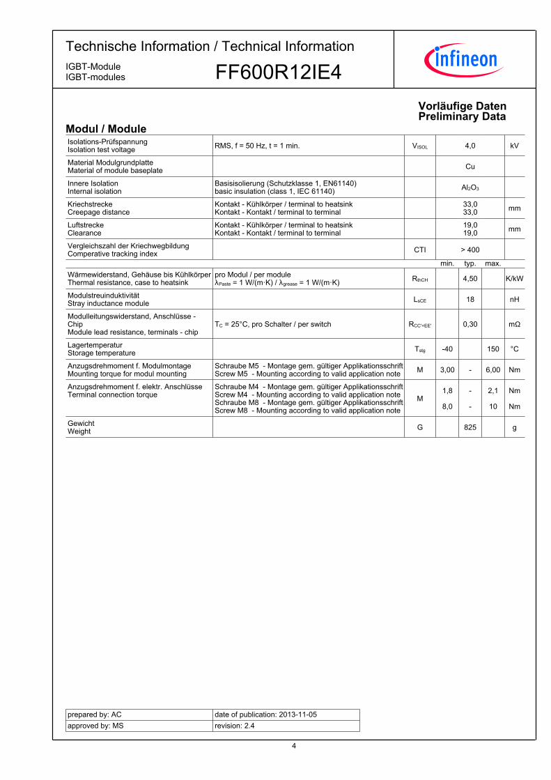
Modul/ModuleIsolations-PrüfspannungIsolationtestvoltage RMS, f = 50 Hz, t = 1 min. VISOL 4,0 kV
MaterialModulgrundplatteMaterialofmodulebaseplate Cu
InnereIsolationInternalisolation
Basisisolierung(Schutzklasse1,EN61140)basicinsulation(class1,IEC61140) Al2O3
KriechstreckeCreepagedistance
Kontakt-Kühlkörper/terminaltoheatsinkKontakt-Kontakt/terminaltoterminal 33,0
33,0 mm
LuftstreckeClearance
Kontakt-Kühlkörper/terminaltoheatsinkKontakt-Kontakt/terminaltoterminal 19,0
19,0 mm
VergleichszahlderKriechwegbildungComperativetrackingindex CTI > 400
min. typ. max.
Wärmewiderstand,GehäusebisKühlkörperThermalresistance,casetoheatsink
proModul/permoduleλPaste=1W/(m·K)/λgrease=1W/(m·K) RthCH 4,50 K/kW
ModulstreuinduktivitätStrayinductancemodule LsCE 18 nH
Modulleitungswiderstand,Anschlüsse-ChipModuleleadresistance,terminals-chip
TC=25°C,proSchalter/perswitch RCC'+EE' 0,30 mΩ
LagertemperaturStoragetemperature Tstg -40 150 °C
Anzugsdrehmomentf.ModulmontageMountingtorqueformodulmounting
SchraubeM5-Montagegem.gültigerApplikationsschriftScrewM5-Mountingaccordingtovalidapplicationnote M 3,00 - 6,00 Nm
Anzugsdrehmomentf.elektr.AnschlüsseTerminalconnectiontorque
SchraubeM4-Montagegem.gültigerApplikationsschriftScrewM4-MountingaccordingtovalidapplicationnoteSchraubeM8-Montagegem.gültigerApplikationsschriftScrewM8-Mountingaccordingtovalidapplicationnote
M1,8
8,0
-
-
2,1
10
Nm
Nm
GewichtWeight G 825 g

5
TechnischeInformation/TechnicalInformation
FF600R12IE4IGBT-ModuleIGBT-modules
preparedby:ACapprovedby:MS
dateofpublication:2013-11-05revision:2.4
VorläufigeDatenPreliminaryData
AusgangskennlinieIGBT,Wechselrichter(typisch)outputcharacteristicIGBT,Inverter(typical)IC=f(VCE)VGE=15V
VCE [V]
IC [A
]
0,0 0,5 1,0 1,5 2,0 2,5 3,0 3,50
200
400
600
800
1000
1200Tvj = 25°CTvj = 125°CTvj = 150°C
AusgangskennlinienfeldIGBT,Wechselrichter(typisch)outputcharacteristicIGBT,Inverter(typical)IC=f(VCE)Tvj=150°C
VCE [V]
IC [A
]
0,0 0,5 1,0 1,5 2,0 2,5 3,0 3,5 4,0 4,5 5,00
200
400
600
800
1000
1200VGE = 19VVGE = 17VVGE = 15VVGE = 13VVGE = 11VVGE = 9V
ÜbertragungscharakteristikIGBT,Wechselrichter(typisch)transfercharacteristicIGBT,Inverter(typical)IC=f(VGE)VCE=20V
VGE [V]
IC [A
]
5 6 7 8 9 10 11 120
200
400
600
800
1000
1200Tvj = 25°CTvj = 125°CTvj = 150°C
SchaltverlusteIGBT,Wechselrichter(typisch)switchinglossesIGBT,Inverter(typical)Eon=f(IC),Eoff=f(IC)VGE=±15V,RGon=1.8Ω,RGoff=2.2Ω,VCE=600V
IC [A]
E [m
J]
0 200 400 600 800 1000 12000
30
60
90
120
150
180
210
240Eon, Tvj = 125°CEon, Tvj = 150°CEoff, Tvj = 125°CEoff, Tvj = 150°C
6
TechnischeInformation/TechnicalInformation
FF600R12IE4IGBT-ModuleIGBT-modules
preparedby:ACapprovedby:MS
dateofpublication:2013-11-05revision:2.4
VorläufigeDatenPreliminaryData
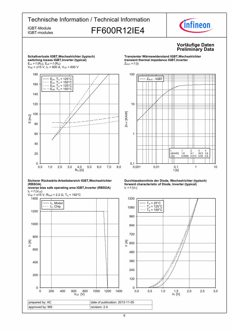
SchaltverlusteIGBT,Wechselrichter(typisch)switchinglossesIGBT,Inverter(typical)Eon=f(RG),Eoff=f(RG)VGE=±15V,IC=600A,VCE=600V
RG [Ω]
E [m
J]
0,0 1,0 2,0 3,0 4,0 5,0 6,0 7,0 8,00
20
40
60
80
100
120
140
160
180Eon, Tvj = 125°CEon, Tvj = 150°CEoff, Tvj = 125°CEoff, Tvj = 150°C
TransienterWärmewiderstandIGBT,WechselrichtertransientthermalimpedanceIGBT,InverterZthJC=f(t)
t [s]
Zth
JC [K
/kW
]
0,001 0,01 0,1 1 100,1
1
10
100ZthJC : IGBT
i: ri[K/kW]: τi[s]:
1 1,8 0,0008
2 9,1 0,013
3 30,5 0,05
4 3,6 0,6
SichererRückwärts-ArbeitsbereichIGBT,Wechselrichter(RBSOA)reversebiassafeoperatingareaIGBT,Inverter(RBSOA)IC=f(VCE)VGE=±15V,RGoff=2.2Ω,Tvj=150°C
VCE [V]
IC [A
]
0 200 400 600 800 1000 1200 14000
200
400
600
800
1000
1200
1400IC, ModulIC, Chip
DurchlasskennliniederDiode,Wechselrichter(typisch)forwardcharacteristicofDiode,Inverter(typical)IF=f(VF)
VF [V]
IF [A
]
0,0 0,5 1,0 1,5 2,0 2,5 3,00
120
240
360
480
600
720
840
960
1080
1200Tvj = 25°CTvj = 125°CTvj = 150°C

7
TechnischeInformation/TechnicalInformation
FF600R12IE4IGBT-ModuleIGBT-modules
preparedby:ACapprovedby:MS
dateofpublication:2013-11-05revision:2.4
VorläufigeDatenPreliminaryData
SchaltverlusteDiode,Wechselrichter(typisch)switchinglossesDiode,Inverter(typical)Erec=f(IF)RGon=1.8Ω,VCE=600V
IF [A]
E [m
J]
0 200 400 600 800 1000 12000
20
40
60
80
100Erec, Tvj = 125°CErec, Tvj = 150°C
SchaltverlusteDiode,Wechselrichter(typisch)switchinglossesDiode,Inverter(typical)Erec=f(RG)IF=600A,VCE=600V
RG [Ω]
E [m
J]
0,0 2,0 4,0 6,0 8,00
10
20
30
40
50
60
70
80
90
100Erec, Tvj = 125°CErec, Tvj = 150°C
TransienterWärmewiderstandDiode,WechselrichtertransientthermalimpedanceDiode,InverterZthJC=f(t)
t [s]
Zth
JC [K
/kW
]
0,001 0,01 0,1 1 100,1
1
10
100ZthJC : Diode
i: ri[K/kW]: τi[s]:
1 6,4 0,0008
2 17,8 0,013
3 49,6 0,05
4 1,2 0,6
NTC-Widerstand-Temperaturkennlinie(typisch)NTC-Thermistor-temperaturecharacteristic(typical)R=f(T)
TC [°C]
R[Ω
]
0 20 40 60 80 100 120 140 160100
1000
10000
100000Rtyp

8
TechnischeInformation/TechnicalInformation
FF600R12IE4IGBT-ModuleIGBT-modules
preparedby:ACapprovedby:MS
dateofpublication:2013-11-05revision:2.4
VorläufigeDatenPreliminaryDataSchaltplan/circuit_diagram_headline
Gehäuseabmessungen/packageoutlines

9
TechnischeInformation/TechnicalInformation
FF600R12IE4IGBT-ModuleIGBT-modules
preparedby:ACapprovedby:MS
dateofpublication:2013-11-05revision:2.4
VorläufigeDatenPreliminaryData
NutzungsbedingungenDieindiesemProduktdatenblattenthaltenenDatensindausschließlichfürtechnischgeschultesFachpersonalbestimmt.DieBeurteilungderEignungdiesesProduktesfürIhreAnwendungsowiedieBeurteilungderVollständigkeitderbereitgestelltenProduktdatenfürdieseAnwendungobliegtIhnenbzw.IhrentechnischenAbteilungen.
IndiesemProduktdatenblattwerdendiejenigenMerkmalebeschrieben,fürdiewireineliefervertraglicheGewährleistungübernehmen.EinesolcheGewährleistungrichtetsichausschließlichnachMaßgabederimjeweiligenLiefervertragenthaltenenBestimmungen.GarantienjeglicherArtwerdenfürdasProduktunddessenEigenschaftenkeinesfallsübernommen.DieAngabenindengültigenAnwendungs-undMontagehinweisendesModulssindzubeachten.
SolltenSievonunsProduktinformationenbenötigen,dieüberdenInhaltdiesesProduktdatenblattshinausgehenundinsbesondereeinespezifischeVerwendungunddenEinsatzdiesesProduktesbetreffen,setzenSiesichbittemitdemfürSiezuständigenVertriebsbüroinVerbindung(siehewww.infineon.com,Vertrieb&Kontakt).FürInteressentenhaltenwirApplicationNotesbereit.
AufgrunddertechnischenAnforderungenkönnteunserProduktgesundheitsgefährdendeSubstanzenenthalten.BeiRückfragenzudenindiesemProduktjeweilsenthaltenenSubstanzensetzenSiesichbitteebenfallsmitdemfürSiezuständigenVertriebsbüroinVerbindung.
SolltenSiebeabsichtigen,dasProduktinAnwendungenderLuftfahrt,ingesundheits-oderlebensgefährdendenoderlebenserhaltendenAnwendungsbereicheneinzusetzen,bittenwirumMitteilung.Wirweisendaraufhin,dasswirfürdieseFälle-diegemeinsameDurchführungeinesRisiko-undQualitätsassessments;-denAbschlussvonspeziellenQualitätssicherungsvereinbarungen;-diegemeinsameEinführungvonMaßnahmenzueinerlaufendenProduktbeobachtungdringendempfehlenundgegebenenfallsdieBelieferungvonderUmsetzungsolcherMaßnahmenabhängigmachen.
Soweiterforderlich,bittenwirSie,entsprechendeHinweiseanIhreKundenzugeben.
InhaltlicheÄnderungendiesesProduktdatenblattsbleibenvorbehalten.
Terms&ConditionsofusageThedatacontainedinthisproductdatasheetisexclusivelyintendedfortechnicallytrainedstaff.Youandyourtechnicaldepartmentswillhavetoevaluatethesuitabilityoftheproductfortheintendedapplicationandthecompletenessoftheproductdatawithrespecttosuchapplication.
Thisproductdatasheetisdescribingthecharacteristicsofthisproductforwhichawarrantyisgranted.Anysuchwarrantyisgrantedexclusivelypursuantthetermsandconditionsofthesupplyagreement.Therewillbenoguaranteeofanykindfortheproductanditscharacteristics.Theinformationinthevalidapplication-andassemblynotesofthemodulemustbeconsidered.
Shouldyourequireproductinformationinexcessofthedatagiveninthisproductdatasheetorwhichconcernsthespecificapplicationofourproduct,pleasecontactthesalesoffice,whichisresponsibleforyou(seewww.infineon.com).Forthosethatarespecificallyinterestedwemayprovideapplicationnotes.
Duetotechnicalrequirementsourproductmaycontaindangeroussubstances.Forinformationonthetypesinquestionpleasecontactthesalesoffice,whichisresponsibleforyou.
ShouldyouintendtousetheProductinaviationapplications,inhealthorliveendangeringorlifesupportapplications,pleasenotify.Pleasenote,thatforanysuchapplicationsweurgentlyrecommend-toperformjointRiskandQualityAssessments;-theconclusionofQualityAgreements;-toestablishjointmeasuresofanongoingproductsurvey,andthatwemaymakedeliverydependedontherealizationofanysuchmeasures.
Ifandtotheextentnecessary,pleaseforwardequivalentnoticestoyourcustomers.
Changesofthisproductdatasheetarereserved.