TECHNIQUES TO OPTIMIZE USAGE OF SATELLITE RF POWER
28
31 st Space Symposium, Technical Track, Colorado Springs, Colorado, United States of America Presented on April 13-14, 2015 Copyright © 2015 by X.T. Vuong/Artel, LLC. All rights reserved. Page 1 of 28 TECHNIQUES TO OPTIMIZE USAGE OF SATELLITE RF POWER Dr. X.T. Vuong, VP and Chief Scientist Artel, LLC, Herndon, Virginia, [email protected] ABSTRACT Power is a primary resource for a communication satellite. With conventional satellite payload design, one often encounters problems of under-utilization of RF power available on one channel (or one transponder or one downlink beam) that would waste available RF power and over-utilization requirement of RF power available on another, resulting in denial of services. The under-utilization and over-utilization problems can be avoided with any of the two technologies/techniques called ATPA (Active Transmit Phased Array) and MARS (Matrix Amplifier and Routing System). With ATPA or MARS, the available satellite RF power is automatically pooled and shared together. Other than power sharing, ATPA allows the beams to be shaped/steered via their Beam Forming Networks (BFNs). ATPA also allows use of many low-power HPAs (e.g., SSPAs), vice a few high-power HPAs (e.g., TWTAs), to improve reliability. Iridium (S-Band, 1997) and Spaceway (Ka-Band, 2007) are two examples of satellites that implemented ATPA. Matrix amplifier has many other names such as matrix transponder, multi-port amplifier. It initially lent itself to the scanned radar technology by using the Butler matrix to automatically pool and share power among HPAs. It was later enhanced to also include its capability of routing signals to different downlink beams without placing any switches or multiplexers after the HPA outputs and the term MARS was created to reflect its capability enhancement. Inmarsat-3 (L-Band, 1995) and AMSC/TMI's MSAT-1/TMI-1 (L-Band, 1995), ETS-6 (S-Band,1996) and E172B (Ku-Band, 2017) are examples of satellites that implemented or will implement MARS. This paper will describe the two techniques together with their principle parameters and characteristics. For ATPA, the characteristics include Intermod Beams and regrowth of shaped beams due to amplifier nonlinearity. For MARS, the characteristics include the routing vectors and creation of inter-port intermodulation products. I. INTRODUCTION RF bandwidth and power are the two primary resources of a communication satellite. The former is limited by the bandwidth allocated by the ITU according to the ITU services that the satellite intends to provide, e.g., Ku-band FSS. The allocated bandwidth can be reused through spatial diversity of its satellite beams and polarization discrimination. The latter is limited by the amount power that can be provided by the satellite bus via its solar arrays. With conventional satellite payload design, one often encounters problems of under-utilization of RF power available on one channel (or one transponder or one downlink beam) that would waste available RF power and over-utilization requirement of RF power available on another, resulting in denial of services. The under-utilization and over-utilization problems can be avoided with any of the two techniques called Active Transmit Phased Array (ATPA) and Matrix Amplifier and Routing System (MARS). With ATPA or MARS, the available RF satellite power is automatically pooled together and automatically shared. This paper will describe the two techniques together with their principle parameters and characteristics.
Transcript of TECHNIQUES TO OPTIMIZE USAGE OF SATELLITE RF POWER

31st
Space Symposium, Technical Track, Colorado Springs, Colorado, United States of America Presented on April 13-14, 2015
Copyright © 2015 by X.T. Vuong/Artel, LLC. All rights reserved. Page 1 of 28
TECHNIQUES TO OPTIMIZE USAGE OF SATELLITE RF POWER
Dr. X.T. Vuong, VP and Chief Scientist
Artel, LLC, Herndon, Virginia, [email protected]
ABSTRACT
Power is a primary resource for a communication satellite. With conventional satellite payload design, one
often encounters problems of under-utilization of RF power available on one channel (or one transponder or one
downlink beam) that would waste available RF power and over-utilization requirement of RF power available on
another, resulting in denial of services. The under-utilization and over-utilization problems can be avoided with
any of the two technologies/techniques called ATPA (Active Transmit Phased Array) and MARS (Matrix Amplifier
and Routing System). With ATPA or MARS, the available satellite RF power is automatically pooled and shared
together.
Other than power sharing, ATPA allows the beams to be shaped/steered via their Beam Forming Networks
(BFNs). ATPA also allows use of many low-power HPAs (e.g., SSPAs), vice a few high-power HPAs (e.g., TWTAs), to
improve reliability. Iridium (S-Band, 1997) and Spaceway (Ka-Band, 2007) are two examples of satellites that
implemented ATPA.
Matrix amplifier has many other names such as matrix transponder, multi-port amplifier. It initially lent itself
to the scanned radar technology by using the Butler matrix to automatically pool and share power among HPAs. It
was later enhanced to also include its capability of routing signals to different downlink beams without placing any
switches or multiplexers after the HPA outputs and the term MARS was created to reflect its capability
enhancement. Inmarsat-3 (L-Band, 1995) and AMSC/TMI's MSAT-1/TMI-1 (L-Band, 1995), ETS-6 (S-Band,1996) and
E172B (Ku-Band, 2017) are examples of satellites that implemented or will implement MARS.
This paper will describe the two techniques together with their principle parameters and characteristics. For
ATPA, the characteristics include Intermod Beams and regrowth of shaped beams due to amplifier nonlinearity.
For MARS, the characteristics include the routing vectors and creation of inter-port intermodulation products.
I. INTRODUCTION
RF bandwidth and power are the two primary resources of a communication satellite. The former is limited by
the bandwidth allocated by the ITU according to the ITU services that the satellite intends to provide, e.g., Ku-band
FSS. The allocated bandwidth can be reused through spatial diversity of its satellite beams and polarization
discrimination. The latter is limited by the amount power that can be provided by the satellite bus via its solar
arrays.
With conventional satellite payload design, one often encounters problems of under-utilization of RF power
available on one channel (or one transponder or one downlink beam) that would waste available RF power and
over-utilization requirement of RF power available on another, resulting in denial of services. The under-utilization
and over-utilization problems can be avoided with any of the two techniques called Active Transmit Phased Array
(ATPA) and Matrix Amplifier and Routing System (MARS). With ATPA or MARS, the available RF satellite power is
automatically pooled together and automatically shared.
This paper will describe the two techniques together with their principle parameters and characteristics.

31st
Space Symposium, Technical Track, Colorado Springs, Colorado, United States of America Presented on April 13-14, 2015
Page 2 of 28
II. ATPA
II.1 ATPA Description
ATPA is a blend of transponder and antenna technologies/techniques that has become feasible for satellite
development because of advances in monolithic microwave integrated circuits (MMIC) amplifiers, attenuators, and
phase shifters1, 2, 3, 4
. The weight, volume, and uniformity in performance of their components are critical to the
design and implementation of ATPAs. With MMIC, a large number of components can be replicated to provide
more or less the same characteristics with minimal tuning. MMIC also provides high levels of integration that
minimizes parasitic effects from bonding and wiring and results in the reduction of weight and volume. These
characteristics make the design of ATPAs possible.
ATPA, as depicted in Exhibit II.1, consists of the following components:
M beam input ports,
One beam forming matrix (BFM),
K solid state power amplifiers (SSPAs),
K output circuits, and
K radiating elements.
Signals entering from each beam input port will be split into K components with appropriate phases and
powers by the BFM. The phase and powers of these components are also modified as they pass through the
SSPAs, the output circuits, and the radiating elements. Since these components are coherent, they will be
combined together in space at the far field of the radiating elements (i.e., on Earth). The combination is
constructive at the desired main beam directions and destructive at the null directions.
BFM, as depicted in Exhibit II.2, combines the output ports of M beam forming networks (BFNs) with M-to-1
combiners. Each BFN consists of a 1-to-K splitter, and K pairs of attenuators/amplifiers and phase shifters. The
values of the pairs are called the beam-weights of a BFN. Depending on the design, these attenuators/amplifiers
and phase shifters may be programmable to provide variable loss/gain values (beam-weight magnitudes) and
phase shift values (beam-weight phases) to steer and reconfigure the shapes of the beams.
The output circuits are components placed between the SSPAs and the radiating elements. These circuits may
include components such as cables, waveguides, filters, and directional couplers. For practical design, to maximize
available RF power, the SSPAs are often placed right at the inputs of the radiating elements.
Because each SSPA is accessed by all carriers, the available RF power from the SSPAs are pooled together and
shared among the carriers. In general, to simplify the design and operation, a beam is often shaped/steered
through adjustment of just only the phases of the beam-weights of the BFNs (the beam-weight magnitudes are
kept the same); then the available RF power is shared equally among the beams and the carriers.
Note that ATPA provides better reliability for the same level of redundancy as a conventional satellite payload.
It is because it uses many low power SSPAs which are more liable than high power TWTAs (travelling wave tube
amplifiers) and failure of a few of them will only somewhat degrade the performance of the transmit beam
coverage areas. In contrast, with a conventional satellite payload, the failure of a high power HPA will result in a
total loss of a beam or a transponder, unless substantial redundancy, e.g., 2-for-1 or 3-for-2 is employed.
Iridium (S-Band, 1997) and Spaceway (Ka-Band, 2007) are two examples of satellites that implemented ATPA.
II.2 ATPA Performance
To access the performance of ATPAs requires the development of a new software tool as software tools to
analyze the performance of conventional payloads cannot be used in general3, 5, 6
. This is because unlike the
performance analysis for conventional satellite payloads, amplifier nonlinearity affects and beam forming analyses
cannot in general be decoupled and therefore cannot be analyzed separately. The ATPA performance analysis is
more complex and time consuming as it requires blending of amplifier loading analyses for each SSPA and the

31st
Space Symposium, Technical Track, Colorado Springs, Colorado, United States of America Presented on April 13-14, 2015
Page 3 of 28
beam forming analyses for each carrier and generated inter-modulation product (IMP). This complexity is even
more evident when multiple BFNs are used since each SSPA must support all carriers from all beams.
In order to evaluate the performance of an ATPA, a conventional transmit satellite payload is defined as a
reference to compare against. Logically, the Equivalent Passive Transmit Phased Array (EPTPA), depicted in Exhibit
II.3, is selected as the reference. EPTPA is an ATPA with its SSPAs removed and replaced by HPAs placed in front of
the BFM, with one HPA for each beam input. The HPAs are assumed to be identical and have the same gain and
normalized AM/AM and AM/PM transfer functions as the SSPAs (which are also assumed to be identical). Because
an ATPA consists of many SSPAs and the nonlinear performances of these SSPAs are part of the ATPA
performances, so another reference parameter is also needed to define for reference comparison: EIPBO
(effective input backoff). EIPBO is the average of the IPBOs of the SSPAs; when the beam-weight magnitudes are
set to be equal, the SSPAs are all operated at the same input backoff which is EIPBO. Nevertheless, when the
beam-weights are set to be unequal some SSPAs operate above and some below EIPBO.
ATPA performances are provided here for three cases. They are based on a study conducted for DISA/CFSE3;
more and detailed results can be found in references3, 5, 6
.
II.2.1 Case1: Single Beam, Equal Beam-Weight Magnitudes
Case 1 involves a single beam (i.e., a single BFN) with its beam-weight magnitudes being set equal. It can be
proved mathematically and through computer simulation that the performances of the APTA are identical to those
of its EPTPA. That is:
GATPA = GEPTPA = GPTPA + GHPA
(C/IM)ATPA = (C/IM)HPA
GATPA, GEPTPA, GPTPA, and GHPA are the gains experienced by a carrier as it passes through the ATPA, EPTPA, PTPA,
and HPA respectively, and (C/IM)ATPA and (C/IM)HPA are the intermodulation performances of the ATPA and the HPA
respectively. That is for these special simple cases, the ATPA analysis can be decomposed to loading analysis of a
single amplifier8, 9
and beam forming analysis of a passive transmit phased array3.
II.2.2 Case 2: Single Beam, Unequal Beam-Weight Magnitudes
For this case the transmit beam is formed through adjustment of also the beam-weight magnitudes. The use
of unequal beam-weight magnitudes is desirable to shape the beam and to introduce a beam taper that reduces
sidelobe levels.
Exhibits II.4 and II.5 are gain patterns of the ATPA versus EIPBO for Case 2 with 10 equal-power carriers (and a
specific set of 64 radiating elements with a specific set of beam-weights and radiating elements). From the
patterns it is observed that the first sidelobes of the gain patterns (that were suppressed by beam tapering) regrow
with decreasing EIPBO (increasing total input power). Even though this regrowth phenomenon is observed for a
specific scenario of Case 2, it is also true for any other scenarios of Case 2, with different carriers, radiation
elements and beam weights. This regrowth phenomenon is analogous to the well known spectral sidelobe
regrowth of a filtered PSK carrier when it is passed through a nonlinearity (e.g., an HPA). Control of sidelobe levels
is important for migrating potential interference to other beams within the system or to adjacent satellite and
terrestrial systems; thus care must be exercised when an ATPA is deployed and used with unequal beam-weight
magnitudes.
The spatial gain pattern of the ATPA is not the same as its EPTPA, but it approaches that of its EPTPA with
increased EIPBO.
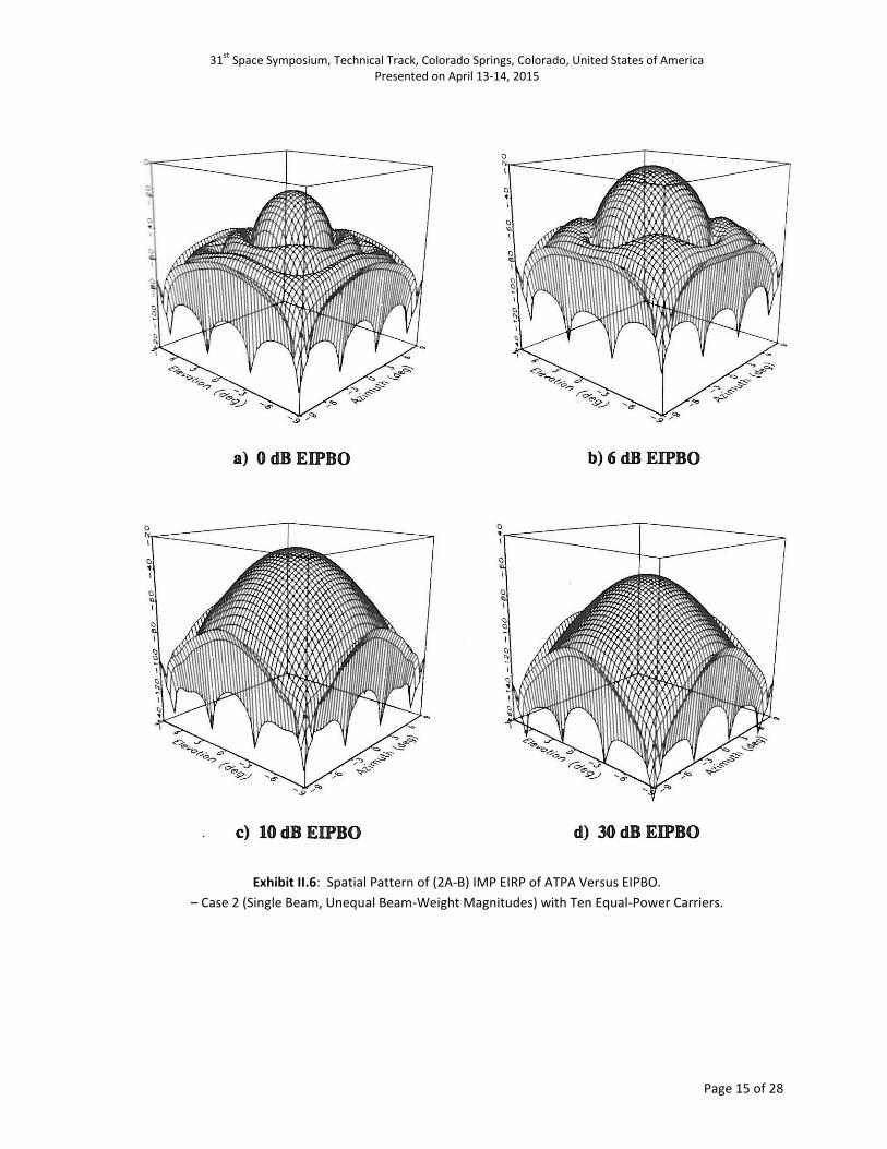
For the intermodulation performances, the C/IM pattern of the ATPA improves (i.e., has higher values) but
does not approach that of its EPTPA with increased EIPBO. Exhibit II.6 shows the spatial patterns of the EIRP of a
third order (2A-B) IMP for the ten-equal-power-carrier scenario.

31st
Space Symposium, Technical Track, Colorado Springs, Colorado, United States of America Presented on April 13-14, 2015
Page 4 of 28
Note that for Case 2, a high-power carrier (L) and a low-power carrier (S) do not experience the same gains
and same phase shifts as they pass through the SSPAs. Accordingly, the characteristics of the beam-weights must
be adjusted for the carriers and therefore the spatial gain patterns of the carriers will not be the same, as depicted
in Exhibit II.7. Their corresponding (2A-B) IMPs also have different EIRP patterns and are shown Exhibit II.8.
II.2.3 Case 3: Two Beams, Equal Beam-Weight Magnitudes
For this case the ATPA beam-weight phases are adjusted to form transmit beams in two directions (two
transmit beams). Scenarios with each beam supporting equal-power carriers were considered. Through
simulation, it was found that the gain of the ATPA is approximately equal to that of its EPTPA; the total C/IM for
the ATPA is worse than that of its EPTPA for any direction within a main beam. Intuitively, these results are
expected because each SSPA is accessed by all carriers, as opposed to the EPTPA in which each HPA is accessed by
only the carriers within the beam supported by the particular HPA.
At the main beams of the ATPA and its EPTPA, the IM effects are differentiated by two factors: a) the number
of carriers accessing each nonlinearity (4 for the ATPA and 2 for the EPTPA) and b) the number of 3rd
order IM
beams (the number of beam-weight sets for all 3rd
order IMPs) generated (6 for the ATPA and 2 for the EPTPA).
The latter improves the IM performance of the ATPA relative to that of the EPTPA because the total IMP power is
spread among more beams. This spatial dispersal effect reduces the IM interference on the main beams of the
ATPA. Nevertheless, it creates IM beams at other locations that may be a source of interference to adjacent
satellite and terrestrial systems; thus care must be exercised when an ATPA is deployed and used to support
multiple beams.
Exhibit II.9 depicts the locations of the six IM beams. Two of the IM beams coincide with the two carrier
(main) beams and are called Principal IM beams. Two of the other IM beams are “collinear” with the carrier beams
and the angular distances between these two IM beams and the carrier beams are the same as the angular
distance between the two carrier beams. The arrangement of the spatial locations of these IM beams relative to
those of the carrier beams is analogous to the arrangement of the frequency locations of the two 3rd
order
intermodulation products (2A-B) and (2B-A) relative to the frequency locations of the two carriers (A and B).
Accordingly, these two IM beams are named as intermodulation-beam products or IBxIB beams. The spatial
locations of the last two IB beams are found to be symmetrical to those of the IBxIB beams. The general
arrangement of the IBxIB beams in relation to those of the carrier beams has been studied by Sandrin7.
III. MARS
III.1 MARS Description
MARS is a satellite payload technology/technique that can be applied to communication satellites to increase
capacity and flexibility. MARS allows automatic sharing of satellite RF power among channels (transponders or
downlink beams). It also allows the routing of signals from each uplink beam or channel to one or more downlink
beams without placing any switches or multiplexers after the HPA outputs, thus reducing satellite payload
complexity and output circuit losses. MARS is suitable for the design of satellite systems that require multiple
downlink beams to cover different geographical areas with traffic loads that are substantially different and time-
varying, e.g., HTS (High Throughput Satellite) systems. The power sharing concept was first developed at COMSAT
Laboratories14, 15
. It was initially based on the scanned radar technology by using the Butler matrix16, 17
as its Input
Matrix and Output Matrix building blocks (see Exhibit III.1) and called the Butler Transponder. Later more research
work was conducted on the power sharing technology and names other than Butler Transponder for the same
concepts were also used: Matrix Amplifier, Mutiport Amplifier, Hybrid Amplifier, Matrix Transponder, Multiport
Transponder, and Hybrid Transponder18
. The power sharing concept was generalized and enhanced to include its
routing capability, and accordingly the term MARS (Matrix Amplifier and Routing System) was introduced and

31st
Space Symposium, Technical Track, Colorado Springs, Colorado, United States of America Presented on April 13-14, 2015
Page 5 of 28
used10-13
. The first satellites to implement MARS were Inmarsat-3 (launched in 1995), AMSC/TMI's MSAT-1/TMI-1
(1995), and SkyTerra-1 (2010) at L-Band and ETS-6 (1996) at S-Band. MARS has advanced to Ku-Band with
Eutelsat’s E172B to be launched in 2017 to serve its Ku-Band HTS payload19
.
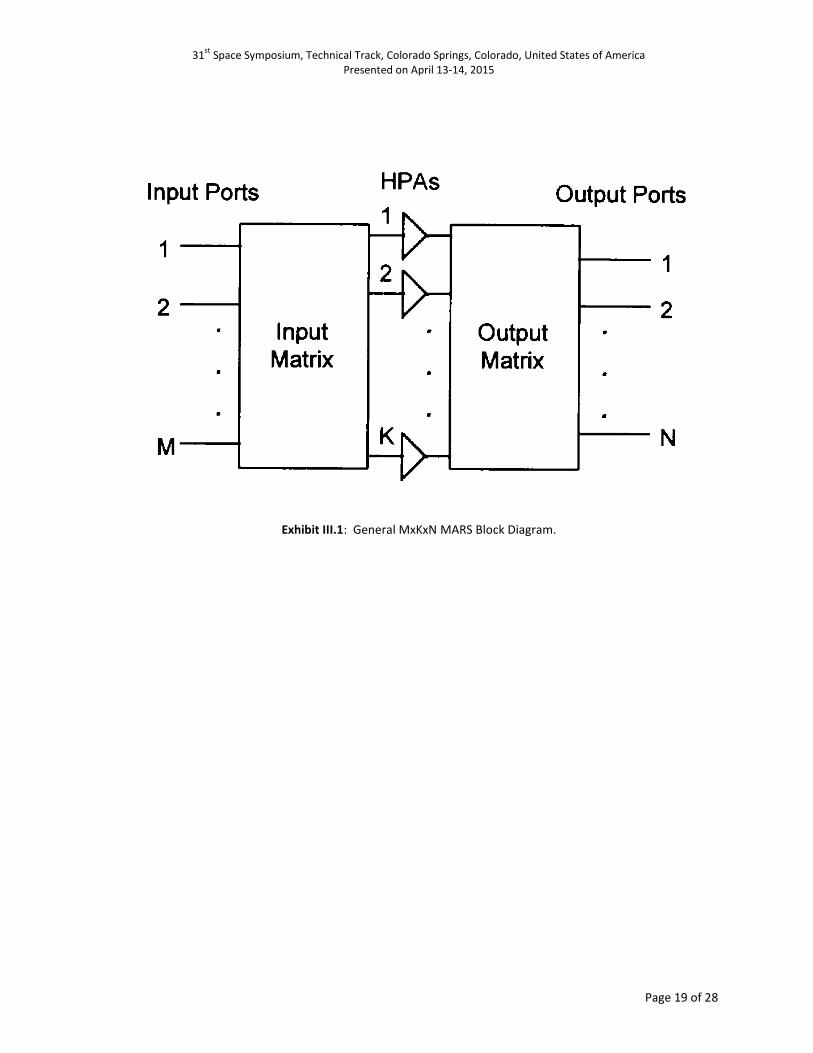
As shown in Exhibit III.1, a generic MxKxN MARS consists of the following components:
M input ports (1, …, m, …, M),
N input ports (1, …,n, …, N),
K identical HPAs (1, …, k, …, K) K > N,
One KxM input matrix, and
One NxK output matrix.
Each signal entering one of the M input ports is split into K components of supposedly equal power and
appropriate phases set by the input matrix. Each of these components, after amplification by one of the K
supposedly identical HPAs, is split further by the output matrix to N subcomponents of supposedly equal power
and appropriate phases. Consequently at each MARS output port, there will be a total of KN equal power
subcomponents. These components are coherent (i.e., originated from the same source) and therefore their
voltages are combined together vectorially. The combination can be destructive (totally out-of-phase),
constructively (totally in-phase) or somewhere in between (depending on the phases set by the input and output
matrices), resulting in the routing to one or more of the output ports. For MARS to be able to automatically share
the HPA power among the ports, the number of the output ports must not exceed the number of the HPAs (i.e., N
< K).
Since the HPAs are assumed to be identical and each is loaded with the same number of signal components of
the same magnitudes (but different phases), the K components of each signal, after passing through the HPAs, will
experience the same voltage gain and the same phase shift. This implies that the HPAs do not have any effects on
the routing of signals. They do, however, have nonlinear effects, e.g., intermodulation effects which degrade the
BER-performance of signals, and will be briefly addressed in Section III.2.
Defining P(KxM) and Q(NxK) as the matrix transfer functions of the input and output matrices, and pkm and qnk
as their corresponding entries, then by definition,
Mag(pkm) = |pkm| = constant (= (1/K)1/2
for lossless input matrix) (1)
Mag(qnk) = |qnk| = constant (= (1/N)1/2
for lossless output matrix) . (2)
Then the complete (input-to-output) matrix transfer function T(NxM) for MARS, excluding the nonlinearity effects
of the HPAs, is:
T = Q P (3)
Defining T and P by their column vectors, i.e.,
T = [t1 : t2 : … tm : … : tM] (4)
P = [p1 : p2 : … pm : … : pM] (5)
Then
tm = Q pm (6)
where pm is the column #m of the matrix P which represents the vector transfer function from MARS input port #m
to the output ports of the input matrix; and tm is the column #m of the matrix T which represents the vector
transfer function MARS input port #m to the MARS output ports.
From Eq. (6) it is noted that the output matrix Q affects the routing of all signals (i.e., signals entering any
MARS input ports), but the column vector pm of the input matrix P only affects the routing of signals entering
MARS input port #m. Accordingly, if the required routing of signals change from time to time, it is desirable to fix
the characteristics of the output matrix and only change the characteristics (more precisely the phases) of the
columns of the input appropriately. The phase component of the column vector pm is termed the Routing Vector
of MARS input port #m. The squares of the magnitudes of the column vector tm is termed the Power Distribution
Vector associated with the Routing Vector.

31st
Space Symposium, Technical Track, Colorado Springs, Colorado, United States of America Presented on April 13-14, 2015
Page 6 of 28
Routing Vector (of input port #m) = Ang(pm) = [Ang(p1m) Ang(p2m) … Ang(pkm) … Ang(pKm)]T (7)
Power Distribution Vector = [|t1m|2 |t2m|
2 … |tnm|
2 … |tNm|
2]
T (8)
Note that the dimension of the routing vector is K; however, the routing is based on the relative values of the
phases, one phase value is redundant and can be fixed to any arbitrary value and the rest can be made
programmable.
When MARS is used as a power-sharing-only system with fixed one-to-one routing between the input and
output ports, the following relationships must hold true:
M = N (9)
T = Q P = c E (10)
Where c is a complex constant; and E is a row interchanging transformation matrix which has one and only one “1”
at each row (and column) and “0” for any other entries. The square matrix E includes the symmetric identity
matrix I and the rotated identity matrix IR:
III.1.2 Power-Sharing-Only MARS - Realization
To construct a power-sharing-only MARS with one-to-one routing, the input and output matrices must satisfy
the requirements described by Eqs. (1), (2), (9), and (10) and must be physically realizable by microwave
components. When the number of HPAs K is an integral power of 2 (i.e., K =2x for any positive integer x), it can be
shown that a power-sharing-only MARS can be constructed with general matrices G(KxK)’s10
. G(KxK) is defined
recursively by Exhibit II.2 where G(2x2) is a regular microwave hybrid (i.e., (1:1, 90o-lag) hybrid or coupler) and
G(2Kx2K) can be constructed from two hybrid matrices G(KxK)’s and K regular hybrids G(2x2)’s with two
connection rules as described in Exhibit III.2. Note that it can be shown10
that there are totally N1 different
G(2Kx2K)’s that can be constructed from G(KxK)’s and totally N2 different G(2Kx2K)’s that can be constructed from
G(2x2)’s, where:
N1 = 2K K! (11)
N2 = (2K K!) (2
K-1 (K-1)!) … (2
2 2!) (12)
Note that G(2x2) or (1:1, 90o-lag) hybrid is also called a (3-dB, 90
o) hybrid and its matrix transfer function is
Two families of the hybrid matrix G are of interest: the hybrid H family (shown in Exhibit III.3) and the
symmetric hybrid matrix S family (shown in Exhibit III.4). The hybrid matrix H is the Butler matrix without its phase
shifters (i.e., phase shifter values set zeros) and symmetric hybrid matrix S is symmetric (ST = S). Note that the
Butler matrix17
is a special kind of BFN that is used with a linear array of radiating elements in radar application to
form equally-spaced scanning beams; the Butler is formed with alternate columns of regular hybrids and phase
shifters16
.
It can be shown that the general hybrid matrix G(KxK) has the following properties10
:
GT(KxK) G(KxK) = (-j)
x I
R(KxK) (13a)
G(KxK) GT(KxK) = (-j)
x I
R(KxK) (13b)
G*T
(KxK) G*(KxK) = (-j)
x I
R(KxK) (13c)

31st
Space Symposium, Technical Track, Colorado Springs, Colorado, United States of America Presented on April 13-14, 2015
Page 7 of 28
G*(KxK) G
*T(KxK) = (-j)
x I
R(KxK) (13d)
and
G*T
(KxK) G(KxK) = I(KxK) (14a)
GT(KxK) G
*(KxK) = I(KxK) (14b)
G*(KxK) G
T(KxK) = I(KxK) (14c)
G(KxK) G*T
(KxK) = I(KxK) (14d)
These fit the general requirements described by Eq. (10) for a power-sharing-only MARS. Note that K = 2x; (j)
2 = -1;
GT is the transpose of G or physically a mirror image of G (i.e., the input ports of G become the output ports of G
T
and vice versa); and G* is the complex conjugate of G (i.e., a G whose phase component changes sign) or physically
a G whose (1:1, 90o-lag) hybrids are replaced by (1:1, 90
o-lead) hybrids.
A power-sharing-only MARS can be formed based on any of Eqs. (13a) - (13d) and (14a) – (14b). For instance,
if Eq. (13a) is used, then the first matrix of the LHS of the equation (GT(KxK)) is the MARS input matrix and the
last/second matrix (G(KxK)) of the LHS of the equation is the MARS output matrix; and signals entering MARS input
port #m will be routed to MARS output port #(K+1-m) for m = 1, 2, …, M. Similarly, if Eq. (14d) is used, then the
first matrix of the LHS of the equation (G (KxK)) is the MARS input matrix and the last/second matrix (G*T
(KxK)) of
the LHS of the equation is the MARS output matrix; and signals entering MARS input port #m will be routed to
MARS output port m for m = 1, 2, …, M. Note that for a power-sharing-only MARS (with one-to-one routing), the
number of input ports M must be equal to the number of output ports N and must not exceed the number of HPAs
K. Note also that when M or N is less than K, some hybrids of the hybrid matrices may be unused and can removed
and unused ports are connected to match load.
III.1.3 Flexible Routing MARS - Realization
The routing concept of the MARS technology/technique is inherent in the power sharing concept. To utilize
MARS’s routing capability, the output matrix should be realized by a general hybrid matrix G(KxK), the input matrix
can be realized like BFM with equal beam-weight magnitudes, i.e., by M 1:K dividers, M(K-1) phase shifters, and K
M:1 combiners, as shown in Exhibit III.5. Routing results are addressed in the next section.
III.2 MARS Performance
MARS performances with respect to routing capability, under effects of HPA nonlinearities, and under
practical conditions where hybrids and HPAs are not ideal/identical were extensively studied and reported10
. Some
results are summarized here.
III.2.1 Routing Capability
Exhibit III.6 summarizes routing results for (MxKxK) MARS for K = 2 and 4 and with 2-bit phase shifters (i.e.,
with four different relative phase shift values 0o, -90
o, -180
o, and -270
o. The results show that with 2-bit phase
shifters, signals from one input port can always be routed to any one output port, to any two output ports
simultaneously with equal power split, and to all output ports simultaneously with equal power split (broadcast
operation).
When the values of the phase shifters are not restricted, the number of ways that signals from one input port
can be routed to the output ports increases significantly. For K = 2, signals from one input port can be routed to
both output ports with any proportion of power split. For other values of K of the form K = 2x where x is a positive
integer, it is not possible (with the basic MARS design) to route signals from one input port to the output ports
with any arbitrary proportion of the power split. For instance (for K = 2x and K > 2 with the basic MARS design), it is
not possible to route signals from one input port to two output ports with unequal power split, and to three, five,
six and seven of the output ports.

31st
Space Symposium, Technical Track, Colorado Springs, Colorado, United States of America Presented on April 13-14, 2015
Page 8 of 28
To enhance the routing capability, two (or more) input ports can be used to route the same signals to the
output ports. With the enhancement, signals can now be routed to any two output ports with any proportion of
power split, and to any three output ports, etc. The enhancement requires use of extra input ports, and more
importantly some signals entering MARS are now coherent to each other. Signal coherence causes the HPAs to
share the traffic load unevenly and that may require the HPAs to operate at a greater power backoff. Signal
coherence was addressed in Reference10
and is a topic that requires further study.
III.2.2 MARS Nonlinearity
In contrast to conventional satellite payloads in which a single HPA is used to amplify only a limited number of
signals (i.e., carriers); associated with a channel or a transponder; a MARS HPA is accessed by all signals appearing
at every MARS input port, thus causing a larger number of intermodulation products (IMPs). Like the signals, these
IMPs are coherent with those IMPs generated by the other MARS HPAs and their voltages are combined vectorially
at the output ports. There are two types of IMPs: intra-port IMPs (IMPs created by signals of the same input port)
and inter-port IMPs (IMPs created by signals of multiple input ports). Intra-port IMPs have the same relative phase
characteristics as their corresponding signals and therefore they are combined in the same way as the
corresponding signals. That is, they are routed to the same output ports as their corresponding signals. Inter-port
IMPs, however, may or may not have the same relative phase characteristics as any of their corresponding signals
and therefore may or may not be combined at the output ports in the same manner as the signals.
Inter-Port IMP Destinations
For a one-to-one routing MARS using a hybrid matrix G as its output matrix, there three interesting general
results on destinations of inter-port third-order IMPs:
The output port destination of a (2A-B) IMP is the output port destination of signal B.
The output port destination of an (A+B-C) IMP is the output port destination of signal A, if signal B
and signal C have the same output port destination.
The output port destination of an (A+B-C) IMP is the output port destination of signal C, if signal A
and signal B have the same output port destination.
Exhibit III.7 provides all results of destinations of (A+B-C) and (2A-B) IMPs as a function of destinations of
signals A, B, and C for MARS with G(8x8) – which can be H(8x8) as shown in Exhibit III.3 or S(8x8) as shown in
Exhibit III.4. To illustrate the use of the exhibit, the 1st
, 15th
and 36th
elements of the 6th
column of the exhibit [i.e.,
(6 1 1), (1 2 5) and (1 6)] are selected. Suppose there are two signals (f1 and f2) at output port #1, one signal (f3)
at output port #2, three signals (f4, f5 and f6) at output port #5, and one signal (f7) at output port #7; then below are
the IMPs associated with the port-types (6 1 1), (1 2 5) and (1 6) appearing at the output port #6:
(6 1 1): (f7 + f1 – f2) and (f7 + f2 – f1)
(1 2 5): (f1 + f3 – f4), (f1 + f3 – f5), (f1 + f3 – f6), (f2 + f3 – f4), (f2 + f3 – f5), and (f2 + f3 – f6)
(1 6): (2f1 – f7) and (2f2 – f7)
Inter-Port IMP Power Levels and Phases
The power of an (A+B-C) IMP is independent from destinations of the signals A, B, and C. That is, an inter-port
(A+B-C) IMP has the same power as an intra-port (A+B-C) IMP, as long as the corresponding signals A, B, and C of
the inter-port IMP have the same power level as those of the intra-port IMP. Similar results are also true for a (2A-
B) product.
The relative phase of an (A+B-C) IMP (i.e., the phase excluding those imbedded in the signals) are either the
same or 180o different from each other, if the corresponding signals A, B, and C have the same power levels.
Similar results are also true for a (2A-B) product.

31st
Space Symposium, Technical Track, Colorado Springs, Colorado, United States of America Presented on April 13-14, 2015
Page 9 of 28
IM Performance: MARS Versus Conventional Payload System
For comparison, the MARS has K input ports, K HPAs, and K output ports; the conventional (no-power sharing)
payload system has K identical HPAs; and each input port of the two systems is loaded with equal number (Z) of
carriers (signals) which are equal in power and equally spaced in frequency. From analyses and simulated results,
the following conclusions can be made:
- When frequency reuse is not employed at the input ports, MARS improves the IM performance over the
conventional payload system.
- When the frequency band associated with each input port is fully reused, the IM performance of the
MARS is worse than but approaches that of the conventional payload system as Z increases.

31st
Space Symposium, Technical Track, Colorado Springs, Colorado, United States of America Presented on April 13-14, 2015
Page 10 of 28
Exhibit II.1: General ATPA Block Diagram

31st
Space Symposium, Technical Track, Colorado Springs, Colorado, United States of America Presented on April 13-14, 2015
Page 11 of 28
Exhibit II.2: General BFM Block Diagram

31st
Space Symposium, Technical Track, Colorado Springs, Colorado, United States of America Presented on April 13-14, 2015
Page 12 of 28
Exhibit II.3: General EPTPA Block Diagram

31st
Space Symposium, Technical Track, Colorado Springs, Colorado, United States of America Presented on April 13-14, 2015
Page 13 of 28
Exhibit II.4: Spatial Gain Pattern of ATPA Versus EIPBO.
– Case 2 (Single Beam, Unequal Beam-Weight Magnitudes) with Ten Equal-Power Carriers.

31st
Space Symposium, Technical Track, Colorado Springs, Colorado, United States of America Presented on April 13-14, 2015
Page 14 of 28
Exhibit II.5: Two-Dimensional Gain Pattern (Azimuth Cut) of ATPA Versus EIPBO.
– Case 2 (Single Beam, Unequal Beam-Weight Magnitudes) with Ten Equal-Power Carriers.
31st
Space Symposium, Technical Track, Colorado Springs, Colorado, United States of America Presented on April 13-14, 2015
Page 15 of 28
Exhibit II.6: Spatial Pattern of (2A-B) IMP EIRP of ATPA Versus EIPBO.
– Case 2 (Single Beam, Unequal Beam-Weight Magnitudes) with Ten Equal-Power Carriers.

31st
Space Symposium, Technical Track, Colorado Springs, Colorado, United States of America Presented on April 13-14, 2015
Page 16 of 28
Exhibit II.7: Spatial Gain Patterns of Large Carrier and Small Carrier.
– Case 2 (Single Beam, Unequal Beam-Weight Magnitudes) with Two Unequal-Power Carriers.

31st
Space Symposium, Technical Track, Colorado Springs, Colorado, United States of America Presented on April 13-14, 2015
Page 17 of 28
Exhibit II.8: Spatial Patterns of (2L-S) and (2S-L) IMP EIRPs.
– Case 2 (Single Beam, Unequal Beam-Weight Magnitudes) with Two Unequal-Power Carriers.

31st
Space Symposium, Technical Track, Colorado Springs, Colorado, United States of America Presented on April 13-14, 2015
Page 18 of 28
Exhibit II.9: Spatial Locations of the Six 3rd
Order IM Beams.
– Case 3 (Two Beams, Equal Beam-Weight Magnitudes) with Two Equal-Power Carriers Per Beam.
31st
Space Symposium, Technical Track, Colorado Springs, Colorado, United States of America Presented on April 13-14, 2015
Page 19 of 28
Exhibit III.1: General MxKxN MARS Block Diagram.

31st
Space Symposium, Technical Track, Colorado Springs, Colorado, United States of America Presented on April 13-14, 2015
Page 20 of 28
Exhibit III.2: Recursive Definition of General Hybrid Matrix G(KxK).

31st
Space Symposium, Technical Track, Colorado Springs, Colorado, United States of America Presented on April 13-14, 2015
Page 21 of 28
Exhibit III.3: Hybrid Matrix H(KxK) Family – K = 2, 4, 8, and 16.

31st
Space Symposium, Technical Track, Colorado Springs, Colorado, United States of America Presented on April 13-14, 2015
Page 22 of 28
Exhibit III.4: Hybrid Matrix S(KxK) Family – K = 2, 4, 8, and 16.

31st
Space Symposium, Technical Track, Colorado Springs, Colorado, United States of America Presented on April 13-14, 2015
Page 23 of 28
Exhibit III.5: Input Matrix of Flexible Routing MARS.

31st
Space Symposium, Technical Track, Colorado Springs, Colorado, United States of America Presented on April 13-14, 2015
Page 24 of 28
Exhibit III.6: Routing Results for (MxKxK) MARS for K = 2 and 4 with 2-Bit Phase Shifters.

31st
Space Symposium, Technical Track, Colorado Springs, Colorado, United States of America Presented on April 13-14, 2015
Page 25 of 28
Exhibit III.7: Output Port Destinations of Inter-Port Third Order (A+B-C) and (2A-B) IMPs
– One-to-One Routing MARS with Hybrid Matrix G(8x8) As Output Matrix.

31st
Space Symposium, Technical Track, Colorado Springs, Colorado, United States of America Presented on April 13-14, 2015
Page 26 of 28
GLOSSARY
* Complex conjugate operation.
|(.)| Magnitude or amplitude of (.).
A Amplifier or attenuator.
Ang(.) Angle or Phase of (.)
ATPA Active transmit phased array.
BER Bit error rate.
BFM Beam forming matrix.
BFN Beam forming network.
c Complex constant.
C Carrier.
C/IM Carrier to intermodulation.
dB Decibel.
E Row interchanging transformation matrix.
EIPBO Equivalent input backoff.
EIRP Effective isotropic radiated power.
EPTPA Equivalent passive transmit phased array.
FSS Fixed satellite services.
G Gain.
G General hybrid matrix G.
H Hybrid matrix H.
HPA High power amplifier.
HTS High throughput satellite.
I Symmetric identity matrix.
IR Rotated identity matrix.
IB Intermodulation beam.
IM Intermodulation.
IMP Intermodulation product.
ITU International Telecommunication Union.
j Complex symbol where j2 = -1.
K Number of MARS’s HPAs.
K Number of ATPA’s SSPAs or radiating elements.
LHS Left hand side.
M Number of MARS’ input ports.
M Number of ATPA’s input ports.
Mag(.) Magnitude or Amplitude of (.).
MARS Matrix amplifier and routing system.
MMIC Monolithic microwave integrated circuits.
N Number of MARS’ output ports.
NPR Noise power ratio.
P Phase shifter.
P Matrix transfer function of MARS’s input matrix.
PSK Phased shift keying
PTPA Passive transmit phased array.

31st
Space Symposium, Technical Track, Colorado Springs, Colorado, United States of America Presented on April 13-14, 2015
Page 27 of 28
Q Matrix transfer function of MARS’s output matrix.
RF Radio frequency.
S Symmetric hybrid matrix S.
SSPA Solid state power amplifier.
T Matrix transpose operation.
T Matrix transfer function of MARS.
TPA Transmit phased array.
TWTA Travelling wave tube amplifier.

31st
Space Symposium, Technical Track, Colorado Springs, Colorado, United States of America Presented on April 13-14, 2015
Page 28 of 28
REFERENCE 1R.M. Sorbello, A.I. Zaghloul, R.K. Gupta, B.D. Geller, and F.T. Assal, ”A Ku-Band Multibeam Active Phased Array
for Satellite Communications,” Proceedings of the AIAA 14th
International Communication Satellite Systems
Conference, Washington, D.C., March 1992.
2D. Michel, B. Cogo, S. Bertrand, D. Roques, B.V. Saint-Andre, M. Belfort, and J.C. Zehen, ”A Ku-Band Active
Antenna Program,” Proceedings of the AIAA 14th
International Communication Satellite Systems Conference,
Washington, D.C., March 1992. 3X.T. Vuong, H. Paul, and S. Hryckiewicz, Active Transmit Phased Array Analysis, Final Report Prepared by SAIC
for DISA/CFSE under Contract DCA 100-90-C-0058, December 1992. 4High Power Active Transmit Phased Array, Final Report Prepared by COMSAT Laboratories for Air Force
Materiel Command, Rome Laboratory, under Contract F30602-92-D-0133 (with SAIC Acted as Prime Contractor),
August 1994. 5X.T. Vuong, H. Paul, and S. Hryckiewicz, ”Active Transmit Phased Array Analysis,” Classified Proceedings of the
IEEE Military Communications Conference (Unclassified Paper in Classified Sessions), Boston, October 1993. 6X.T. Vuong, ”Active Transmit Phased Array Analysis Program (ATPAL),” Proceedings of the IEEE International
Symposium on Phased Array Systems and Technology, Boston, October 1996. 7W.A. Sandrin, ”Spatial Distribution of Intermodulation Products in Active Phased Array Antennas,” IEEE
Transactions on Antenna and Propagation, November 1973. 8J.C. Fuenzalida, O. Shimbo, and W. Cook, ”Time Domain Analysis of Intermodulation Effects Caused by
Nonlinear Amplifiers,” COMSAT Technical Review, Spring 1973. 9D.S. Arnstein, X.T. Vuong, C.B. Cotner, and H.M. Daryanani, ”The IM Microscope: A New Approach to
Nonlinear Analysis of Signals in Satellite Communications Systems,” COMSAT Technical Review, Spring 1992. 10
X.T. Vuong, H.I Paul, and D. Cole, Matrix Amplifier and Routing System (MARS), Final Report Prepared by SAIC
for USAF/SMC under Contract No. F25606-91-D0005, August 1993. 11
X.T. Vuong, H.I. Paul, and D. Cole, ”Matrix Amplifier and Routing System (MARS),” Classified Proceedings of
the IEEE Military Communications Conference (Unclassified Paper in Classified Sessions), Boston, October 1993. 12
X.T. Vuong, H.I. Paul, and D. Cole, ”Application of Matrix Amplifier and Routing System (MARS) Technology to
Future DoD Satellite Payload Designs,” Classified Proceedings of the IEEE Military Communications Conference
(Unclassified Paper in Classified Sessions), Boston, October 1993. 13
X.T. Vuong, ”Matrix Amplifier and Routing System (MARS) Analysis Program,” Proceedings of the IEEE
Military Communications Conference, Monterey, November 1997. 14
G.R. Welti, ”Butler Matrix Transponder Improvements,” US Patent Application, Serial No. 412399, November
1972. 15
W.A. Sandrin, ”The Butler Matrix Transponder,” COMSAT Technical Review, Fall 1974. 16
H.J. Moody, ”The Systematic Design of the Butler Matrix,” IEEE Transactions on Antennas and Propagation,
November 1964. 17
J. Butler and R. Lowe, ”Beamforming Matrix Simplifies Design of Electronically Scanned Antennas,”
Electronic Design, April 1961. 18
S. Egami and M. Kawai, ”An Adaptive Multiple Beam System Concept,” IEEE Journal on Selected Areas in
Communications, May 1987. 19
Private Communication with Bernard Kasstan of Eutelsat, Paris, France, March, 2014.