Techniques for the growth of large single crystals of ... for the Growth of Large Single Crystals of...
6
----------------------------------------------- -- JOURNAL OF RESEAR CH of the Nat iona l Burea u of Standards - A. Physics and Chemi s tr y Vol. 7 1 A, No. 2, March- April 1967 Techniques for the Growth of Large Single Crystals of Potassium of High Purity * Howard J. Foster 1 Institute for Materials Research, National Bureau of Standards, Washington, D.C. 20234 and Paul H. E. Meijer 2 Institute for Basic Standards, National Bureau of Standards, Washington, D.C. 20234 (Dece mber 5, 1966) Th e pr e pa ra ti on of large, hi gh purit y, single crystals of po ta ss ium is d esc ribed. First, high initial purity is obt ained by ca r eful zone refinin g. Th en, a modifi ca ti on of the Bridgman tec hnique is ap plied whi ch leads to crystals with resistivity rati os up to 6800 at 4.2 o K. Th e modific ation consisted of a heat s hi e ld as d es cribed in the tes t. We co nclud ed from the mag net oaco us ti c exp er iment s that we re subse quently done with th ese samples, that th e sa mples had mea n fr ee paths of the order of 10- 2 c rn . Typica l crystals we re 7/ 8 in di a m a nd a bout 8 in long, with growth dir ec ti on along [110]. A de· sc rip ti on is given of an e asy method of orie nt a ti on as we ll as t.h e use of a spark erosion tec hnique to c ut and polish the s urfac es . Key Words: Cry stal growth, fermi s urface, o ri enta ti on, potassium, spark cUlling, zo ne refinin g. 1. Introduction Th e unav ailability of large crystals of the alkali metals on a co mm erc ial b as is a nd the lack of know- how in th e lab ora tory fo r pre paring a nd handlin g th ese highly reactive metals of ade quat e s iz e a nd pu rity co ntinu e to be th e chief reasons for the limited amo unt of experime nt al data on the properti es of th ese metals. Th eir uniqu e a nd s impl e elec tro ni c and crystal s tru c- tur es have alw ays made th em a ttr ac tive from a th eo- retical point of vie w. As a con se qu ence, one finds in the litera tur e that the experime nt al studi es have tended to lag behind the tr eme nd ous a mount of the o- retical work on th e alkali es . Thi s, in turn , ha s stimulated some int er es t in the developme nt and/or the refineme nt of exis ting t ec hnique s for prep ar in g the alkali me tal s for various typ es of experimental s tudi es. In the la st few yea rs there have bee n some reports of progr ess in establishing t ec hniqu es for preparin g s in gle crystal sp ec imens of some of the alkali metals. Among th ese ar e th e tec hniqu es d esc ribed by Daniel s [lJ 3 for s odium. Later, Grim es [2J gave a desc rip- tion of t ec hniqu es that he use d in th e pr e parati on of the alkali metal s, so dium a nd pota ss ium , for cyclotron r eso nan ce s tudi es. More r ece ntly, Hoyte and Miel- *Supported in part by the U.S. AEC. Grant No. AT(40- I)- 286 1. Based on portion of thesis submilt cd in partiaJ rul flil ment of the requirements for the Ph. D. degree to the Depa rt men l of Physics, the Catholic Univers it y of Amer ica. Was hington, D.C. I Temporaril y on leave. Prese nt address: Departme nt of Ph ysics. Alabama A & M Coll ege . No r mal, Alabama 35762. 2. Al so wi th Catholic Uni versity of America . 620 Mic hi gan Ave., NE., Washington, D.C. 20017. :I Figures in brac ke ts indieate the lit erature refe rences at the end of this paper. c zarek [3 J publi shed a pap er on the growth of lar ge single crystals of pot ass ium ; however there is no eviden ce in their pap er of the level of purit y obt ained. In the above referen ces, as in th e pr ese nt pa per, th e methods have much in common, es p ec ially in r ega rd to the tec hniqu e of cryslal growth, i.e., vi a the Bridgman t ec hniqu e. Th e main differen ce in the pr ese nt work is the introdu ction of a hea t shield, which pr eve nt ed the pre mature solidifi ca ti on of the top of th e melt. Th e crys tal s grown by this me th od were sub se - qu e ntl y use d to me asure the magn e toa c ousti c ab- sor ption in order to dete rmine the Fermi s urfa ce of pota ss ium [4]. From the re s ult of these mea s ur e- ments it was c oncluded that th e mean fr ee path is about 10- 2 cm. Th e s ame s ampl es we re us ed in an att e mpt to defe ct the Ove rhau s er spin den sity wav es [5] a nd meas ur e ment s of the resistivity ratio (at Brown Universit y) gave valu es of 6800 and lower [6] . We fee l that the good quality of th e cr ys tals o btain ed is due to the fact that they were both zo ne re fin ed, to re du ce the "c he mi c al " impuriti es as much as poss ibl e, and c ar efully grown, to re du ce the dislocations and other mec hanical imp e rfec tions to a minimum . Th e heat shield preve nt s the reentr y of impuriti es in the higher la yers of the boule, and a ss ur es that they will arri ve at the top where they ca n be eas ily removed. 2. Crystal Growth of Potassium Despite th e fact that the pot ass ium as re ce ived from the MSA R ese ar ch Corpo r ation , Callery, Pa., was reportedly of the order of 99.97 percent purity , we 127
Transcript of Techniques for the growth of large single crystals of ... for the Growth of Large Single Crystals of...
----------------------------------------------- --
JOURNAL OF RESEARCH of the National Burea u of Standards - A. Physics and Chemistry
Vol. 7 1 A, No. 2, March- April 1967
Techniques for the Growth of Large Single Crystals of Potassium of High Purity *
Howard J. Foster 1
Institute for Materials Research, National Bureau of Standards, Washington, D.C. 20234
and Paul H. E. Meijer 2
Institute for Basic Standards, National Bureau of Standards, Washington, D.C. 20234
(Dece mber 5, 1966)
The prepa ra tion of large , high purity, single c rystal s of potass ium is described . First , high initial pu rity is obtained by careful zone refinin g. Then, a modifica tion of the Bridgman technique is applied which leads to crys tals with res istivity ratios up to 6800 at 4.2 oK. The modifi cation consisted of a hea t s hi e ld as descr ibed in the tes t. We concluded from the magnetoacousti c experiments that we re su bseque ntly do ne with these s ampl es , that the sa mpl es had mean free pa ths of th e order of 10- 2 c rn . T yp ical c rysta ls we re 7/ 8 in di a m and a bout 8 in long, with growth direc tion along [110]. A de· scrip tion is g iven of a n e asy method of orienta tion as well as t.h e use of a spark e rosion technique to c ut a nd polish the surfaces .
Key Words : Crysta l grow th , fe rmi surface , ori e ntation, potass ium , s park cUlling, zone refinin g.
1. Introduction
The unavailability of large crys tals of the alkali me tals on a commercial basis and the lack of knowhow in the laboratory for pre paring and handling these highly reac tive me tals of adequate size and purity continue to be the c hief reasons for the limited amount of experimental data on the properties of these metals. Their unique and simple elec tronic and crys tal structures have always made them attractive from a theoretical point of view. As a consequence, one finds in the literature that the experimental studies have tended to lag be hind the tremendous a mount of theoreti cal work on the alkalies . This, in turn , has stimulated some interest in the de velopment and/or the refineme nt of existing techniques for preparing the alkali metals for various types of experimental studies.
In the last few years there have been so me re ports of progress in establishing techniques for preparing single crystal specimens of some of the alkali metal s. Among these are the techniques described by Daniels [lJ 3 for sodium. Later , Grimes [2J gave a description of techniques that he used in the preparation of the alkali me tals, sodium and potassium, for cyclotron resonance studies. More recently , Hoyte and Miel-
*Supported in part by the U.S. AEC. Grant No. AT(40- I )- 286 1. Based on portion of thes is submilt cd in part iaJ rul flil ment of the req uirements for t he Ph. D. degree to the Depa rt men l of Physics, the Catholic University of America. Washington, D.C.
I T empora ril y on leave . Present add ress: Department of Phys ics. Alabama A & M College. Normal, Alabama 35762.
2. Also wi th Catholic Uni versity of Amer ica. 620 Michigan Ave., NE., Washington, D.C. 20017.
:I Figures in brac ke ts indieate the lit erature references at the end of this paper.
czare k [3 J published a paper on the growth of large single crys tals of potass ium ; howe ve r there is no e vidence in their paper of the le vel of purity obtained . In the above references, as in the present pape r, the methods have much in co mmon, especially in regard to th e technique of cryslal growth , i.e., via the Bridgma n technique . The main difference in the present work is the introduction of a heat shield , whic h prevented the premature solidification of the top of the melt.
Th e crys tals grown by thi s method were s ubsequently used to measure the magnetoacoustic absorption in order to determine the F ermi s urface of potassium [4]. From the res ult of these measureme nts it was concluded that the mean free path is about 10- 2 cm. The same sampl es were used in an atte mpt to defect the Overhauser spin density waves [5] a nd measurements of the re s istivit y ratio (at Brown University) gave values of 6800 and lower [6].
We feel th at the good qu ality of the crys tals obtained is du e to the fac t that they we re both zone re fin ed , to reduce the "che mi cal " impurities as much as possible, and carefully grown , to reduce the di slocations a nd other mechanical imperfections to a minimum. The heat s hield prevents the reentry of impuriti es in the higher layers of the boule, and assures that th ey will arri ve at the top where th ey can be easily re moved.
2. Crystal Growth of Potassium
Despite the fact that the potassium as received from the MSA Researc h Corporation , Callery, Pa., was re portedly of the order of 99.97 percent purity , we
127
found, co ntrary to reference 3, that it is necessary to zone-refine the material beforehand_ The theoretical and practical as pects of nucleation and crys tal growth from the melt have been adequately described by Holmes [7], Tiller [8] , Goss [9], and others. The zonerefined metal was subjected to a modified version of the Bridgman technique to grow s ingle crystals under paraffin oil in a stainless steel crucible in the atmosphere. With this method, solidifi cation of the crys talline phase from its melt is initiated in a sharply pointed tip at the lower end of the crucible, under proper temperature conditions. The phase transformation is continuously driven by the controlled extraction of heat through the initially formed crystal seed in the nucleation tip throughout the growth process.
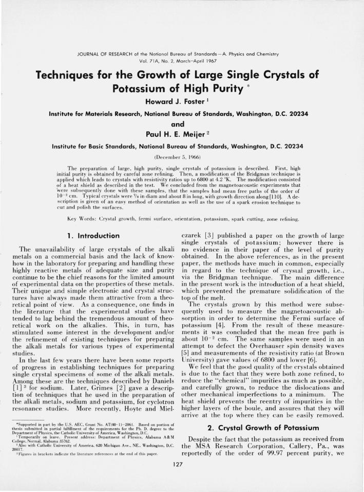
The detachable two piece stainless steel crucible e/8 in ID and about 9 in overall length) is illustrated in figure 1. The upper portion is wound with about 70 turns of asbestos-covered nichrome wire (B & S #20), arranged in gradient fashion over all but about 1/ 4 in of each end of the cylinder, from six turns per inch near the bottom to adjacent turns for the last 1112 in near th e top. This portion is thermally insulated with a preparation of high temperature cement, in order to insure increased electrical heating efficiency and minimum heat loss through the crucible wall during the growth of the potassium single crystals. An a-c voltage for supplying electrical current through the variable turns of heater wire was used to establish
and maintain a vertical temperature gradient ~i through the molten boule. The bottom detachable
HEAT SHIELD OF PYREX LINED CEMENT
SAUEREISEN CEMENT
NICHROME WIRE __ -,-_" Bas GAUGE .20
CYLINDER OF STAINLESS STEEL
BANANA PLUG ELECTRODE '-:.....
-'C=::J--+l
COPPER TUBING ---COOLING COI LS
DETACHABL E BOTTOM OF STAINLESS STEEL
, ..
16 TURNS PER INCH ," '.
12 TURNS PER INCH 3 "
liG
," 10 TURNS PER INCH 72 ," '. 8 TURNS PER INCH
13" liG
6 TURNS PER INCH
,"
FIGURE 1. Bridgman crucibLe and heat shieLd arrangement Jor growing the potassium crystaLs in oiL.
portion of the crucible , equipped with cooling coils of copper tubing, provided the proper undercooling conditions for directed heat extraction and crystal growth from the nucleation lip.
The crucible as described above provided a temperature gradient in the molten potassium boule of about 4.24 °C per inch at 20 V input , without undercooling at the bottom_ This corresponded to a temperature of the potassium in the nucleation tip of about 64 °C, i.e., slightly above the solidification point of 63.7 °C, while the top region of this 81f2 in molten boule was at a temperature of about 100°C. At an input heater voltage of 12 V or less the 81f2 in potassium boule became completely solid_ It was, therefore, only necessary to establish the rate of voltage reduction from 20 to 12 V heater input, with proper undercooling, for growth of the molten boule into a large single crystal of potassium. The design of the electrical circuitry for reducing the heater current, while simultaneously extracting heat through the nucleation tip of the boule, was arrived at by trial and error, with some guidance from published data on metal crystal growth rates [8, 9]_ For the crucible design as described above, the rate of crystal growth R of potassium from its melt was estimated at about 1 in per hour, i.e., R= 7 X 10- 4
cm/sec. The manually operated and motor driven variacs, incorporated in the electrical circuitry , provided for constant power input to the heater windings, as well as for automatic increase and/or reduction in the heater power, in the voltage range from 0 to 6 V per hour, as desired. A voltage reduction rate of 1 V per hour, simultaneously with undercooling at the bottom of the crucible, achieved the specified rate of growth of the potassium single crystal. A heat shield surrounding the top 3 in portion of the crucible was used to prevent the formation of "rogue" crystals due to premature solidification of the melt ahead of the advancing solid-liquid interface, near the top of the potassium boule. A plot of the motion of the freezing interface (approximately) with time , under the voltage reduction and cooling conditions for growing the potassium single crystals, is shown in figure 2. It is clear from this figure that without the heat shield the growth rate starts to increase rapidly near the top.
The experimental procedure for growing the potassium crystals was as follows. The zone refined ingots with their impure ends discarded were placed in the crucible, which was coated with paraffin oil to avoid sticking, and tamped with a steel rod to achieve a continuous solid boule. The top of the solid boule, within about 3/4 in of the top of the crucible, was then covered with paraffin oil and the manually driven variac adjusted to an input heating voltage of 30 V_ This corresponded to temperatures of about 130 and 100 °C at the top and bottom regions of the molten boule, respectively. Entrapped gases in the metal and oil, during the initial heating period of about 2 hr, were removed by vibration upon striking the crucible at the bottom. Sometimes it was necessary to cool, remove, etch (with a solution of 1: 50 = sec-butyl alcohol: xylene), and repeat the process for 4 or 5 times before achieving a smooth and solid potassium boule_
128

;r
>
;;; 0: w f-W ;; -.J
'" :;
w f-<! 0:
I f-
" 0 0:
'"
190
180
170
160
150
140
130
120
110
100
90
80
70
60
50
40
I I
I I
~~~~T ~~~t~ ,~THE~~~~~C~F T~O~~~~:~~E--'" I
I I
80TTOM, WITHOUT SURROUNDING HEAT SHIELD.
o
I I
I /
EXTRAPOLATED EFFECT OF HEAT SHIELD ON MOT ION OF FREEZING INTERFACE NEAR TOP OF BOULE DUE TO MINIMIZED HEAT LOSS THROUGH TOP OF CRUCIBLE
200 250 300 350 4 00 450 500 MINUTES
FIGURE 2. Potassium crystal growth rate pLot (approximate) .
. Once this was done, the boule was melted and allowed to "cook" for several hours, usually overnight, at 20 V heater input, corresponding to a te mperature just above the solidification point of the potassium melt in the nucleation tip. With the heat shield in place, a co ntinuous and stead y Row of nitrogen gas, cooled in a bath of liquid nitroge n or dry-ice slush and adjusted to a predetermined rate from a calibration run, was passed through the cooling coils on the bottom portion of th e cru cible. At this point, the motor for driving the variac was actuated to reduce the heater voltage from 2Q V at a rate of 1 V per hour. The crystal growth process, with the prescribed growth rate of 7 X 10- 4 c m/sec or about 1 in/hr, was uninterrupted for a period of about 9 hr to ins ure co mplete solidification of th e boule. The res ulting single crystal potassium boule, 0.875 in in diam e te r and 7 to 8 in long, was the n allowed to cool furth er to room temperature before re moval from the crucible with a plunger. The large sin gle crystals of potassium were subsequently e tched as pre viously described and then stored in paraffin oiL
The polycrys talline top of the otherwise single cr ystal potassium boule in figure 3, is typical of the case of premature solidification ahead of the advancing solid-liquid interface, grown without the use of the heat shield. Single crystal potassium boules 111
FI GURE 3. Potassium crystaL grown without the use of heat shieLd, resuLting in the forma tion of a poLycrys taLLine region near top of bouLe.
oil, all showi~g highly reflecting blaze planes are ,shown in figures 4, 5a, and Sb. The blaze planes are characterized in each of the crystals by bright reRections of light from narrow strips of the cylindrical surface along the entire length of the boule. The single crystal potassium boules, ' displayed in the photographs in figures 4 and 5 were positioned to show one of the peripheral blazes of light along the boule. Photographs shown in figure 5 (a and b) are of the same crys tal boule in paraffin oil , photographed within 30 min (a) and after 12 hr (b) after e tc hing. These photographs illustrate that a reac tion occurs in spite of the precautions taken to protec t the surface . The comparatively high reRec tivity along certain peripheral positions of the crys tal is due to preferential etching in these crys tallographic directions. The brightest planes in these crys tals (determined by methods to be described later) , were found to coincide with (111) directions in the bcc potassium lattice.
129

FIGURE 4. Potassium single crystal positioned to show one of the four visible blaze planes having (J 11) directions along the boule.
3. Orientation and Cutting of the Potassium Single Crystals
Because of the complementary aspects of the orientation and cutting techniques used in the preparation of the potassium single crystal specimens, they are both presented in this section.
The potassium single crystal boules, purified and grown by the techniques described above, were first oriented optically before being cut into specimens by a spark erosion technique. Transmission x-ray diffraction studies of thin samples of these crystals were used to confirm the accuracy of the optical method which provided a rapid method of orientation. They also confirmed that the direction of growth was indeed in the [llOJ-direction. The optical method of orienting the potassium crystals also proved to be reliable and much more convenient than the x-ray technique.
(0) (b)
FIGURE 5. A n illustration of the effect of time after etching on the appearance of one of four \ Ill) blaze planes displayed along the periphery of the same single crystal potassium boule in oil ; photographed (a) within 1/ 2 hI' after etching, and (b) about 12 hI' after etching.
Preferential etching of the potassium single crystal boules in a solution of 1 part sec-butyl alcohol and 50 parts xylene , and allowing the boule to remain in paraffin oil for an hour or more, produced blaze planes of sufficient brightness to specify the orientation of the crystal. The angles between the peripheral blaze planes were determined by rotating the uncut single crystal potassium in oil and measuring the angles in degrees between successive blazes of light from the boule. The simple requirements of the method consisted of a rotating jig, calibrated in degrees , with prOVISIOns for supporting and rotating the uncut crystal in a vertical glass tube under paraffin oil, a
130
I -,

s mall proj ection lamp, and a telescope for observing the intense blazes of light along the boule as the crystal was rotated. The optical arrangement is shown in fi gure 6. The relative angular positions of the blaze planes from each of the potassium crystals grown a nd observed within 2 hr after removal from the etc h were 0, 70, 180, and 250°. From this, the angles between the 4 successive reflecting planes were de termin ed to be 0,70, 1l0, and 70°, with an accuracy of ± 2° The two-fold rotational symmetry of the peripheral blazes of light suggested that the crystal growth direction was [1l0] and that the highly re fl ec ting blaze plan es were all (Ill ), perpendic ular to the crystal growth
aXIs. Note that the measured angular positi o·ns of the blaze planes about the peri phery of the potassium are in agree ment with the (1lI) directions (0, 70.53, 109.47, and 70.53° whic h lies in the (1l0) plane. In addition to the strong ( 1l1 ) blazes, low inte nsity [110] direc tions were observed about the periphery of a s in gle crys tal po tass ium boule after being s tored in p araffin oil for a month. Th ese find ings are not in di sagreeme nt with the observations of Grimes [2] who used a differe nt e tch and observed the bri ghtes t blaze to be (1l0 ). A projec tion of the (1l0) plane (growth direction) showing the pe r-
SINGLE CRYSTAL
HOLD DOWN
SPRING
LIGHT SOURCE
ci::'ECE ROTATING JIG CALIBRATED IN DEGREES
F IGU RE 6. Schematic arrangement Df tlte Dptics and the crys tal bDule in Dil mDunted in a CD axial rD tat ing j ig fD r lDcating the angular pDs itions at which maximum light reflectiDns (blaze planes), Dccur.
131
pe ndicular directions of the high symme try blaze planes observed in potassium is shown in figure 7. The brightest (Ill) blaze planes also served as convenient markers for specifyin g the transverse magnetic field directions in the crys tal, for the ultrasonic attenuation studies [4].
Transmission x-ray diffrac tion s.tudies of thin wafers of the cylindrical boule and peripheral sections in the directions of the bright blazes perpendicular to the growth axis confirmed the optical findings. The thin samples less than !fB in thick for the x-ray studies were cut by a spark erosion technique to be described later. The x-ray specimens were etched, as described above , followed by coating with a thick solution of vaseline and paraffin oil for the protection of the potassium crystal in the atmosphere while mounted in the goniome ter for long x-ray exposures (11/2 hr). F ear of the effect of the vaseline coating on the di s· played diffraction pattern s was re moved by comparative x- ray diffrac tion pattern s of sin gle crystal quartz , with and without the vaseline coating. No effec t of the vaseline coatin g on the diffraction pattern of quartz was observed.
A spark erosion machine, ge nerally used for precision mac hining of hard metals , was used to c ut the potass i u m s in gle c rys tal s. The essential features of the s park eros ion or arc c utting machine are (1) the servo drive n vibratin g head with a chuck for supporting and controlling the verti cal motion of the arcing electrode; (2) the precision mounted table below the head with two degrees of freedom for accurate pos itioning of the samples with res pect to the elec trode for cutting th e desired s pecimen shapes with parallel surfaces; (3) the trans parent e nclosure of the precis ion
[OOIJ
[ III] [Til]
[110] [110]
[IIIJ [i Ii]
[OOIJ
FI GU RE 7 . A ngular positiDns and the identificatiDn Df peripheral blaze planes in pDtassium after etching, in agreement with the [11 OJ growth axis prDjectiDn.
The ( lIl )'s blaze brightest . the ( 110)', and (lOO),s blaze wfth lower intensity.
I b]
Ie]
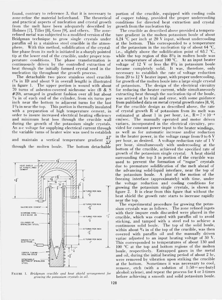
fIGURE 8. Sample holders (a) and (b) and the electrode and support (c) used for cutting the potassium .single crystals by a spark ero.<;'on technique.
table for observation of the arc c utting process in the recirculating dielec tric fluid; and (4) the electrical power supply for automatic operatioh over a wide range of arcing characteristics and cutting s peeds to achieve the desired finish of the arc c ut s urface.
The two sample holders (a) and (b) of stainless steel and brass and the electrode of 0.004 in steel wire mounted in its support (c) are shown in figure 8. The larger sample holder (a) with slotted and removable sections was used to c ut cylindrical s<;l.mples from the single crystal potassium boule. These samples were less than !fa in thick for x-ray diffraction studies of the growth direction and about !f2 in to 5/s. in thick for the ultrasonic studies. The smaller sample holder (b) was used to cut , from short cylindricctl lengths of the crys tal boule, thin peripheral sections in the direction of the blaze planes for x-ray diffraction studies_ A set of in stru ment operating characteris tics for smooth and flat cuts of the potassium crystals, such as the spark gap voltage and curre nt, the feed speed of the chuck mounted electrode in the head, and amplitude of the electrode oscillator, were chosen by trial and error.
The potassium boules or shorter samples were secured in the appropriate holder and mounted on the precision table under the recirculating dielectric fluid. The head with the mounted electrode was lowered by manual control for precision positioning of the wire electrode with r espect to the sample and then lowered further to start the arcing process upon electrical contact with the sample. At this point, automatic operation was switched in , A je t of the dielec tri c fluid was continuously directed at the arc
gap in order to achieve smooth crystal surfaces by removmg the reaction products of the s park erosion process. The dielec tri c fluid, sangajol or terapine generally used with thi s mac hine, had no damaging effect on the potassium s ingle cr ys tals . The arc c utting method eliminated the necess ity for any mechanical polishing of the potassium specimens to achieve smooth, parallel , and flat terminal surfaces of the crystals for th e ultraso nic studies. When desired, polishing was achieved by slow passage of the arcing electrode within 0.005 in of the previously , arc cut rough surface. The arc c utting method was also less time consuming than the string saw and mechanical polishing techniques generally used for pre paring the single crystal specimens of potassium. For example, a spark gap voltage of 75 V dc, with low settings of the other operating characteristics of the spark erosion machine, produced a cut through the i
boule in about 10 min. The resulting arc c ut terminal s urfaces of the potassium single crystal specimens for the ultrasonic attenuation studies at liquid helium temperatures were of a mat finish , flat and parallel, which bonded very well to the transmitting and receiving transducers , using high viscosity (60,000 cs) Dow Corning #510 oil as the bonding agent.
4. Summary
It is intended that the techniques described in this paper will go a long way toward eliminating the trialand-error approach in the preparation of large and pure single crystal specimens of the alkali metal, potassium, for various kinds of experimental studies. It is also worth noting that similar methods presented in this work may be applicable in the preparation of single crystals of the other alkali metals, all of which have very similar physical and chemical properties.
The authors thank Edward A. Stern of the Department of Physics and Astronomy, University of Maryland, for his kind permission to use their spark erosion machine for cutting the potassium crystal specimens.
5. References
[11 W. B. Daniels, Phys. Rev. 119, 1246 (1960). [2] C. C. Grimes, Ph.D. thes is, Unive rsit y of California , 1962
(unpublished). [3] A. F. Hoyte and E. V. Mielczarek, Appl. Mater. Res. 4, 121 (1965). [4] H. J. rQSter, P . ,H. E. Meijer, and E. V. Mielczarek , Phys. Rev.
139, AI849 (1965). [51 M. Greene, A. Hoffman , A. Houghton, R. Pe.ve rley, J. Quinn
and G. Seidel, Phys ics Letters 21, 135 (966) . [6] We are indebt ed to Mr. Hoffman for these values. Some crys
tal s were poorer, but thi s is probab ly due to aging. [7] P. J. Holmes, .I. Phys. Chem. Solids 24, 1239 (1963). [8] W. A. Tiller, The Art and Science of Growing Crys tals, p. 276,
edited by J. J. Gilman (John Wiley & Sons, Inc. , New York , N.Y ., 1963).
[9] A. J. Goss, The Art and Science of Growing Crystals, p. 314, edit ed by J. J. Gilman (John Wiley & Sons , In c. , New York, N.Y., 1963).
(paper 71C2-443) 1 132