TECHNIQUE MANUAL LOCATOR ROOT ATTACHMENT SYSTEM Instruction Manual.pdf · The LOCATOR® Root...
8
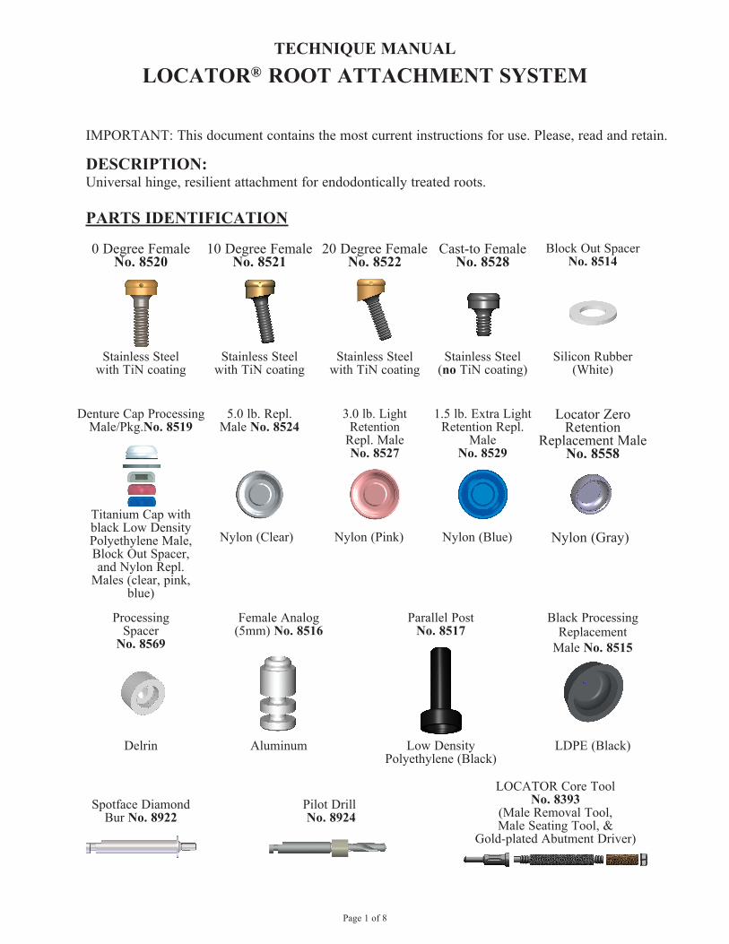
Page 1 of 8 TECHNIQUE MANUAL LOCATOR ® ROOT ATTACHMENT SYSTEM IMPORTANT: This document contains the most current instructions for use. Please, read and retain. DESCRIPTION: Universal hinge, resilient attachment for endodontically treated roots. PARTS IDENTIFICATION LOCATOR Core Tool No. 8393 (Male Removal Tool, Male Seating Tool, & Gold-plated Abutment Driver) Spotface Diamond Bur No. 8922 Pilot Drill No. 8924 Female Analog (5mm) No. 8516 Aluminum Parallel Post No. 8517 Low Density Polyethylene (Black) Processing Spacer No. 8569 Delrin Nylon (Blue) 1.5 lb. Extra Light Retention Repl. Male No. 8529 Nylon (Pink) 3.0 lb. Light Retention Repl. Male No. 8527 5.0 lb. Repl. Male No. 8524 Nylon (Clear) Denture Cap Processing Male/Pkg.No. 8519 Titanium Cap with black Low Density Polyethylene Male, Block Out Spacer, and Nylon Repl. Males (clear, pink, blue) Block Out Spacer No. 8514 Silicon Rubber (White) Cast-to Female No. 8528 Stainless Steel (no TiN coating) 20 Degree Female No. 8522 Stainless Steel with TiN coating 10 Degree Female No. 8521 Stainless Steel with TiN coating Stainless Steel with TiN coating 0 Degree Female No. 8520 Locator Zero Retention Replacement Male No. 8558 Nylon (Gray) Black Processing Replacement Male No. 8515 LDPE (Black)
Transcript of TECHNIQUE MANUAL LOCATOR ROOT ATTACHMENT SYSTEM Instruction Manual.pdf · The LOCATOR® Root...
Page 1 of 8
TECHNIQUE MANUAL
LOCATOR® ROOT ATTACHMENT SYSTEM
IMPORTANT: This document contains the most current instructions for use. Please, read and retain.
DESCRIPTION:Universal hinge, resilient attachment for endodontically treated roots.
PARTS IDENTIFICATION
LOCATOR Core Tool No. 8393
(Male Removal Tool, Male Seating Tool, &
Gold-plated Abutment Driver)
Spotface DiamondBur No. 8922
Pilot Drill No. 8924
Female Analog(5mm) No. 8516
Aluminum
Parallel PostNo. 8517
Low DensityPolyethylene (Black)
Processing Spacer
No. 8569
Delrin
Nylon (Blue)
1.5 lb. Extra LightRetention Repl.
MaleNo. 8529
Nylon (Pink)
3.0 lb. Light Retention
Repl. MaleNo. 8527
5.0 lb. Repl.Male No. 8524
Nylon (Clear)
Denture Cap ProcessingMale/Pkg.No. 8519
Titanium Cap with black Low DensityPolyethylene Male,Block Out Spacer,and Nylon Repl.
Males (clear, pink, blue)
Block Out SpacerNo. 8514
Silicon Rubber(White)
Cast-to FemaleNo. 8528
Stainless Steel(no TiN coating)
20 Degree FemaleNo. 8522
Stainless Steelwith TiN coating
10 Degree FemaleNo. 8521
Stainless Steelwith TiN coating
Stainless Steelwith TiN coating
0 Degree FemaleNo. 8520
Locator Zero Retention
Replacement Male No. 8558
Nylon (Gray)
Black ProcessingReplacement
Male No. 8515
LDPE (Black)
Page 2 of 8
INDICATIONSThe LOCATOR® Root Attachment System is designed for use with overdentures or partial dentures, retained in whole or in part, by endodontically treated roots in the mandible or maxilla.
CONTRAINDICATIONSNot appropriate where a totally rigid connection is required.
CAUTION: Federal (U.S.A.) law restricts this device to sale by or on the order of a licensed dentist.
SINGLE - USE DEVICESLocator Males: The inadvertent re-use of Locator nylon males could cause loss of retention for the overdenture due to wear from previous use or damage during removal with the Locator Core Tool.Locator Root Females: The removal of a cemented Locator Root Female post could fracture the patient’s root. The inadvertent re-use of a female could contain patient contamination build-up and subsequent wear of the retention bands. This would result in the device to perform with improper fit and function which would result in loss of retention for the prosthesis.
STERILIZATIONAll components and instruments are supplied NON-STERILE.Locator Core Tools (in the disassembled state only) may be sterilized by Autoclave orDry Heat sterilization using the following parameters:1. Autoclave sterilize using 121° C (250° F), (15-20 psig at sea level), for 40 minutes minimum.2. Dry Heat sterilize using 170° C (338° F), for 2 hours minimum.
FEATURES1. LOCATING DESIGN: Self-locating design allows a patient to easily seat their
overdenture without the need for accurate alignment of the attachment components.2. RETENTION INSIDE AND OUTSIDE: The unique Dual Retention innovation provides
the Locator attachment with greater retention surface area than ever before available with other attachments. A combination of inside and outside retention ensures the longest lasting performance.
3. CHOICE OF ANGLES AND RETENTION: The Locator attachment is a supra-radicular design which consists of the choice of a straight post and two angles (10 and 20 degrees) to accommodate divergent roots. Three different retentive males allow for your choice of regular, light, or extra-light retention according to the needs of the patient.
4. ROTATIONAL PIVOTING ACTION: The design of the pivoting Locator Male allows a resilient connection for the prosthesis without any resulting loss of retention. The retentive nylon male remains completely in contact with the female socket while its metal denture cap has a full range of rotational movement over the male.
A. PLACEMENT OF THE LOCATOR FEMALE1. Prepare and measure study casts to determine the space available in the root for the Locator
Female. Width of root surface must equal or exceed 4.0mm.2. Decoronate the root and perform endodontic therapy. Remove the desired depth of gutta
percha following standard clinical procedures.3. Finish the contouring of the roots. The final reduction should place the root surface
supragingivally within 1mm of the gingiva. When divergent roots are selected, the occlusal root surfaces should be prepared along the same plane, perpendicular to the intended path of insertion.
Page 3 of 8
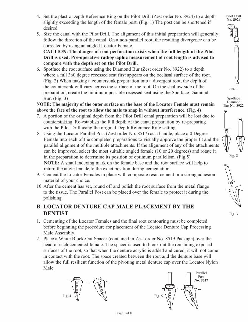
4. Set the plastic Depth Reference Ring on the Pilot Drill (Zest order No. 8924) to a depth slightly exceeding the length of the female post. (Fig. 1) The post can be shortened if desired.
5. Size the canal with the Pilot Drill. The alignment of this initial preparation will generally follow the direction of the canal. On a non-parallel root, the resulting divergence can be corrected by using an angled Locator Female. CAUTION: The danger of root perforation exists when the full length of the Pilot Drill is used. Pre-operative radiographic measurement of root length is advised to compare with the depth set on the Pilot Drill.
6. Spotface the root surface using the Diamond Bur (Zest order No. 8922) to a depth where a full 360 degree recessed seat first appears on the occlasal surface of the root. (Fig. 2) When making a countersunk preparation into a divergent root, the depth of the countersink will vary across the surface of the root. On the shallow side of the preparation, create the minimum possible recessed seat using the Spotface Diamond Bur. (Fig. 3)
NOTE: The majority of the outer surface on the base of the Locator Female must remain above the face of the root to allow the male to snap in without interference. (Fig. 4)7. A portion of the original depth from the Pilot Drill canal preparation will be lost due to
countersinking. Re-establish the full depth of the canal preparation by re-preparing with the Pilot Drill using the original Depth Reference Ring setting.
8. Using the Locator Parallel Post (Zest order No. 8517) as a handle, place a 0 Degree Female into each of the completed preparations to visually approve the proper fit and the parallel alignment of the multiple attachments. If the alignment of any of the attachments can be improved, select the most suitable angled female (10 or 20 degrees) and rotate it in the preparation to determine its position of optimum parallelism. (Fig.5) NOTE: A small indexing mark on the female base and the root surface will help to return the angle female to the exact position during cementation.
9. Cement the Locator Females in place with composite resin cement or a strong adhesion material of your choice.
10. After the cement has set, round off and polish the root surface from the metal flange to the tissue. The Parallel Post can be placed over the female to protect it during the polishing.
B. LOCATOR DENTURE CAP MALE PLACEMENT BY THE DENTIST
1. Cementing of the Locator Females and the final root contouring must be completed before beginning the procedure for placement of the Locator Denture Cap Processing Male Assembly.
2. Place a White Block-Out Spacer (contained in Zest order No. 8519 Package) over the head of each cemented female. The spacer is used to block out the remaining exposed surfaces of the root, so that when the denture acrylic is added and cured, it will not come in contact with the root. The space created between the root and the denture base will allow the full resilient function of the pivoting metal denture cap over the Locator Nylon Male.
Fig. 1
Pilot Drill No. 8924
Fig. 3
Fig. 5
ParallelPost
No. 8517
Fig. 4
SpotfaceDiamond
Bur No. 8922
Fig. 2
Page 4 of 8
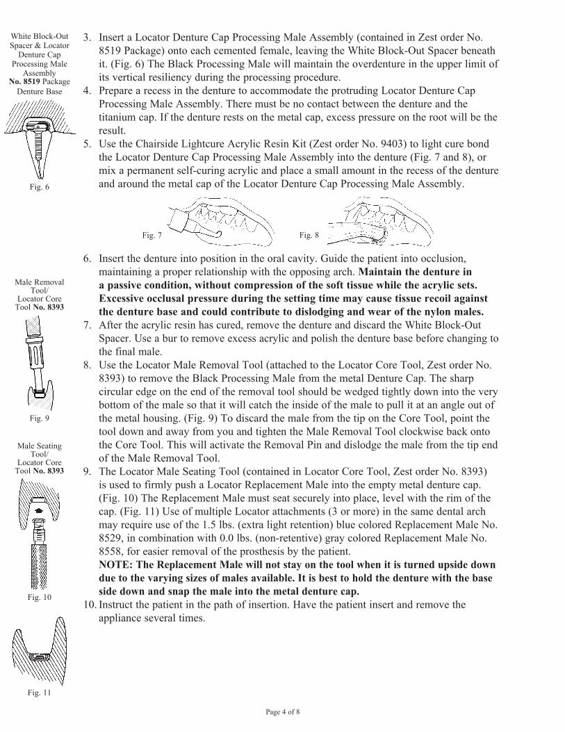
3. Insert a Locator Denture Cap Processing Male Assembly (contained in Zest order No. 8519 Package) onto each cemented female, leaving the White Block-Out Spacer beneath it. (Fig. 6) The Black Processing Male will maintain the overdenture in the upper limit of its vertical resiliency during the processing procedure.
4. Prepare a recess in the denture to accommodate the protruding Locator Denture Cap Processing Male Assembly. There must be no contact between the denture and the titanium cap. If the denture rests on the metal cap, excess pressure on the root will be the result.
5. Use the Chairside Lightcure Acrylic Resin Kit (Zest order No. 9403) to light cure bond the Locator Denture Cap Processing Male Assembly into the denture (Fig. 7 and 8), or mix a permanent self-curing acrylic and place a small amount in the recess of the denture and around the metal cap of the Locator Denture Cap Processing Male Assembly.
Fig. 7
Fig. 8
6. Insert the denture into position in the oral cavity. Guide the patient into occlusion, maintaining a proper relationship with the opposing arch. Maintain the denture in a passive condition, without compression of the soft tissue while the acrylic sets. Excessive occlusal pressure during the setting time may cause tissue recoil against the denture base and could contribute to dislodging and wear of the nylon males.
7. After the acrylic resin has cured, remove the denture and discard the White Block-Out Spacer. Use a bur to remove excess acrylic and polish the denture base before changing to the final male.
8. Use the Locator Male Removal Tool (attached to the Locator Core Tool, Zest order No. 8393) to remove the Black Processing Male from the metal Denture Cap. The sharp circular edge on the end of the removal tool should be wedged tightly down into the very bottom of the male so that it will catch the inside of the male to pull it at an angle out of the metal housing. (Fig. 9) To discard the male from the tip on the Core Tool, point the tool down and away from you and tighten the Male Removal Tool clockwise back onto the Core Tool. This will activate the Removal Pin and dislodge the male from the tip end of the Male Removal Tool.
9. The Locator Male Seating Tool (contained in Locator Core Tool, Zest order No. 8393) is used to firmly push a Locator Replacement Male into the empty metal denture cap. (Fig. 10) The Replacement Male must seat securely into place, level with the rim of the cap. (Fig. 11) Use of multiple Locator attachments (3 or more) in the same dental arch may require use of the 1.5 lbs. (extra light retention) blue colored Replacement Male No. 8529, in combination with 0.0 lbs. (non-retentive) gray colored Replacement Male No. 8558, for easier removal of the prosthesis by the patient.
NOTE: The Replacement Male will not stay on the tool when it is turned upside down due to the varying sizes of males available. It is best to hold the denture with the base side down and snap the male into the metal denture cap.
10. Instruct the patient in the path of insertion. Have the patient insert and remove the appliance several times.
Fig. 6
White Block-Out Spacer & Locator
Denture Cap Processing Male
AssemblyNo. 8519 Package
Denture Base
Fig. 9
Male Removal Tool/
Locator Core Tool No. 8393
Fig. 10
Male Seating Tool/
Locator Core Tool No. 8393
Fig. 11
Page 5 of 8
C. LOCATOR DENTURE CAP MALE PLACEMENT BY THE LABORATORY
In the Operatory:1. Cementing of the Locator Females and the final root contouring must be completed
before beginning the procedure for placement of the Locator Denture Cap Processing Male Assembly.
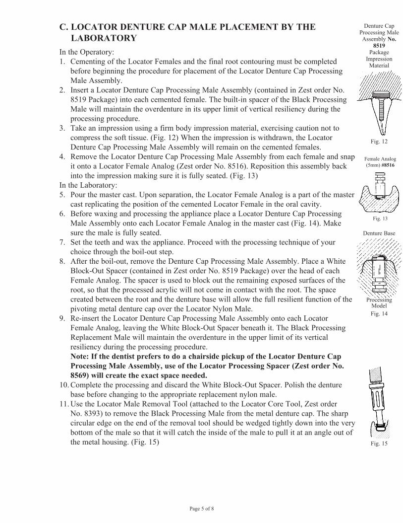
2. Insert a Locator Denture Cap Processing Male Assembly (contained in Zest order No. 8519 Package) into each cemented female. The built-in spacer of the Black Processing Male will maintain the overdenture in its upper limit of vertical resiliency during the processing procedure.
3. Take an impression using a firm body impression material, exercising caution not to compress the soft tissue. (Fig. 12) When the impression is withdrawn, the Locator Denture Cap Processing Male Assembly will remain on the cemented females.
4. Remove the Locator Denture Cap Processing Male Assembly from each female and snap it onto a Locator Female Analog (Zest order No. 8516). Reposition this assembly back into the impression making sure it is fully seated. (Fig. 13)
In the Laboratory:5. Pour the master cast. Upon separation, the Locator Female Analog is a part of the master
cast replicating the position of the cemented Locator Female in the oral cavity.6. Before waxing and processing the appliance place a Locator Denture Cap Processing
Male Assembly onto each Locator Female Analog in the master cast (Fig. 14). Make sure the male is fully seated.
7. Set the teeth and wax the appliance. Proceed with the processing technique of your choice through the boil-out step.
8. After the boil-out, remove the Denture Cap Processing Male Assembly. Place a White Block-Out Spacer (contained in Zest order No. 8519 Package) over the head of each Female Analog. The spacer is used to block out the remaining exposed surfaces of the root, so that the processed acrylic will not come in contact with the root. The space created between the root and the denture base will allow the full resilient function of the pivoting metal denture cap over the Locator Nylon Male.
9. Re-insert the Locator Denture Cap Processing Male Assembly onto each Locator Female Analog, leaving the White Block-Out Spacer beneath it. The Black Processing Replacement Male will maintain the overdenture in the upper limit of its vertical resiliency during the processing procedure.
Note: If the dentist prefers to do a chairside pickup of the Locator Denture Cap Processing Male Assembly, use of the Locator Processing Spacer (Zest order No. 8569) will create the exact space needed.
10. Complete the processing and discard the White Block-Out Spacer. Polish the denture base before changing to the appropriate replacement nylon male.
11. Use the Locator Male Removal Tool (attached to the Locator Core Tool, Zest order No. 8393) to remove the Black Processing Male from the metal denture cap. The sharp circular edge on the end of the removal tool should be wedged tightly down into the very bottom of the male so that it will catch the inside of the male to pull it at an angle out of the metal housing. (Fig. 15)
Denture Cap Processing Male Assembly No.
8519 Package
ImpressionMaterial
Fig. 12Fig. 12
Female Analog (5mm) #8516
Fig. 13
Fig. 14
Denture Base
ProcessingModelFig. 14
ProcessingModel
Fig. 15
Page 6 of 8
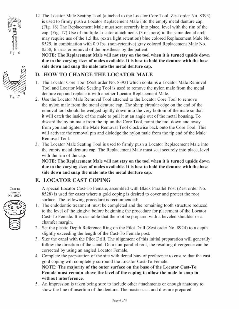
12. The Locator Male Seating Tool (attached to the Locator Core Tool, Zest order No. 8393) is used to firmly push a Locator Replacement Male into the empty metal denture cap. (Fig. 16) The Replacement Male must seat securely into place, level with the rim of the cap. (Fig. 17) Use of multiple Locator attachments (3 or more) in the same dental arch may require use of the 1.5 lbs. (extra light retention) blue colored Replacement Male No. 8529, in combination with 0.0 lbs. (non-retentive) gray colored Replacement Male No. 8558, for easier removal of the prosthesis by the patient. NOTE: The Replacement Male will not stay on the tool when it is turned upside down due to the varying sizes of males available. It is best to hold the denture with the base side down and snap the male into the metal denture cap.
D. HOW TO CHANGE THE LOCATOR MALE1. The Locator Core Tool (Zest order No. 8393) which contains a Locator Male Removal
Tool and Locator Male Seating Tool is used to remove the nylon male from the metal denture cap and replace it with another Locator Replacement Male.
2. Use the Locator Male Removal Tool attached to the Locator Core Tool to remove the nylon male from the metal denture cap. The sharp circular edge on the end of the removal tool should be wedged tightly down into the very bottom of the male so that it will catch the inside of the male to pull it at an angle out of the metal housing. To discard the nylon male from the tip on the Core Tool, point the tool down and away from you and tighten the Male Removal Tool clockwise back onto the Core Tool. This will activate the removal pin and dislodge the nylon male from the tip end of the Male Removal Tool.
3. The Locator Male Seating Tool is used to firmly push a Locator Replacement Male into the empty metal denture cap. The Replacement Male must seat securely into place, level with the rim of the cap.
NOTE: The Replacement Male will not stay on the tool when it is turned upside down due to the varying sizes of males available. It is best to hold the denture with the base side down and snap the male into the metal denture cap.
E. LOCATOR CAST COPING A special Locator Cast-To Female, assembled with Black Parallel Post (Zest order No.
8528) is used for cases where a gold coping is desired to cover and protect the root surface. The following procedure is recommended:
1. The endodontic treatment must be completed and the remaining tooth structure reduced to the level of the gingiva before beginning the procedure for placement of the Locator Cast-To Female. It is desirable that the root be prepared with a beveled shoulder or a chamfer margin.
2. Set the plastic Depth Reference Ring on the Pilot Drill (Zest order No. 8924) to a depth slightly exceeding the length of the Cast-To Female post.
3. Size the canal with the Pilot Drill. The alignment of this initial preparation will generally follow the direction of the canal. On a non-parallel root, the resulting divergence can be corrected by using an angled Locator Female.
4. Complete the preparation of the site with dental burs of preference to ensure that the cast gold coping will completely surround the Locator Cast-To Female.
NOTE: The majority of the outer surface on the base of the Locator Cast-To Female must remain above the level of the coping to allow the male to snap in without interference.
5. An impression is taken being sure to include other attachments or enough anatomy to show the line of insertion of the denture. The master cast and dies are prepared.
Cast-toFemale
No. 8528
Fig. 16
Fig. 17
Page 7 of 8
6. Using a surveyor, place the plastic Parallel Post with attached Cast-To Female parallel with other Locator attachments.
7. Wax the Cast-to Female directly into the die. The wax should be built up to the bottom corner on the base of the female, leaving the majority of the outer surface on the base above the level of the coping.
8. Remove the Parallel Post, leaving the stainless steel attachment open for investment material to flow into.
9. Spruing. Run the sprue at a 45 degree angle to the Cast-To Female so the molten gold will flow down along one side of the female, around and up to the other side. The sprue should not be directed at the female which could possibly dislodge it when casting.
10. It is recommended to use debubblizer to reduce surface tension during investing procedures.
11. Investing. The most successful castings have been accomplished by using Ceramigold Investment by Whip Mix Corp. or an equivalent High Heat Investment. Use a casting ring at all times. (Do not use the ringless technique of investing and casting for the Cast-To Female.)
12. Mix a liquid/powder ratio of Ceramigold using 12ml to 60 grams of powder for each packet of mix needed. Hand mix for 15 seconds and vacuum mix for 90 seconds at (350-450 RPM). The investment material should be carefully painted into each attachment cavity to avoid trapping bubbles and to prevent gold from going inside the female. The remainder of the investment poured into the ring will stabilize the female during burnout. Place the ring in a water bath for one hour, then bench set for a half hour.
13. Burnout. Place ring in a cold furnace (sprue side down) and raise the temperature to 1500° F maximum. Use a rate of climb of 0° F to 1500° F maximum over a time period of one hour. Hold at 1500° F maximum until burnout is complete. (Refer to investment manufacturer’s instructions for suggested burnout duration.)
14. Casting. Use only precious or semi-precious alloys for casting root copings. Base metal alloys should not be used. Cast the coping using recommended temperatures of the alloy manufacturer. The stainless steel female will withstand a temperature of up to 2000° F without any dimensional change. Do not allow casting temperature to raise above 2000° F which will melt the stainless steel female!
15. Divesting. After casting, allow all castings to bench cool for 20 minutes. Be careful to push out the casting and investment with proper tools. It is not recommended to hammer or bang on rings which may distort the castings. To remove the investment material from the Cast-To Female without damage to the stainless steel, use an acid-free investment and porcelain remover solution in an ultrasonic unit for a period of 30-45 minutes. (Do not use a bur to remove the investment, sandblasting with aluminum oxide, or an acid pickling solution, all of which can damage the internal socket of the female attachment.) Clean the coping containing the Locator Cast-To attachment in an ultrasonic cleaner solution.
16. Finishing and Polishing. When polishing with a rubber wheel, use caution not to damage the Cast-To Female attachment. Polish the surface of the coping to make a smooth surface. The Locator Parallel Post can be placed on the female to protect the attachment while polishing. (If additional polishing of the female socket is required, it is recommended to only use glass beads at a low pressure (40 PSI) or a fiberglass or bristle polishing brush.)
17. After polishing the coping, place a Locator Denture Cap Processing Male Assembly (contained in Zest order No. 8519 Package) onto each Cast-To Female and check for proper fit. Clean again in ultrasonic solution and deliver to the dental office.
Page 8 of 8
18. The finished copings containing the Locator Cast-To Female are cemented in place intra-orally on the prepared tooth root.
19. For chairside pick-up into the denture of the Locator Denture Cap Processing Male Assembly (contained in Zest order No. 8519 Package) follow steps in “LOCATOR DENTURE CAP MALE PLACEMENT BY THE DENTIST). If processing of the denture component by the laboratory is desired, follow steps in “LOCATOR DENTURE CAP MALE PLACEMENT BY THE LABORATORY”.
F. RELINE AND REBASE1. Remove each existing nylon male from its metal denture cap following the steps in HOW
TO CHANGE THE LOCATOR MALE (Section D). Replace them with Black Processing Replacement Males (Zest order No. 8515). The built-in spacer of the Black Processing Replacement Male will maintain the overdenture in its upper level of vertical resiliency during the reline process.
2. Take a reline impression using the existing overdenture as a tray. 3. The Black Processing Replacement Males will engage the Locator Females and hold the
prosthesis in place while the impression material sets. When the impression is withdrawn, the Black Processing Replacement Males will remain in the metal denture caps.
4. Snap a Locator Female Analog (Zest order No. 8516) onto each Locator Denture Cap Processing Male Assembly in the impression and pour a master model.
5. After processing the reline and polishing the denture base, replace the Black Processing Replacement Males with the appropriate Locator Nylon Replacement Males.
PATIENT CAREExperts recommend that overdenture abutments should be brushed at least once a day with a gel toothpaste to remove plaque and to stimulate gingival tissues, followed by applying a 0.4% Stannous Fluoride gel.The patient should be instructed to periodically visit their dentist for professional cleanings and attachment evaluation. Use plastic instruments for scaling the attachments. Do not use metal instruments which may create scratches.
RETURN POLICYCheck with your Distributor for their policy on returns.
WARRANTYZest Anchors, LLC provides a limited warranty for its products, to the original purchaser, to be free from defects in workmanship and materials under normal use for a period of one year from the date of purchase. Zest Anchors, LLC will, at its option, substitute the returned product that proves to be defective with a similar product, free of charge.Zest Anchors, LLC continually strives to improve its products, therefore, reserves the right to improve, modify or discontinue products and components at any time without notice or incurring obligation. Purchaser assumes all risks and liability resulting from the use of Zest Anchors, LLC products whether used separately or in combination with other products not of Zest Anchors, LLC manufacture.
2061 Wineridge Place, Escondido, CA 92029 USA(1) 760-743-7744
U.S. Patent Nos. 6,030,219 and 6,299,447LOCATOR® is a registered trademark of Zest IP Holdings, LLC L8001-TM REV E