Technician's instructions 1.001.2849 GENTLEpower LUX Contra … · 2016-02-02 · Technician's...
20
Technician's instructions GENTLEpower LUX Contra-angle 25 LP - REF 1.001.2849
Transcript of Technician's instructions 1.001.2849 GENTLEpower LUX Contra … · 2016-02-02 · Technician's...

Technician's instructions
GENTLEpower LUX Contra-angle 25 LP - REF1.001.2849

Distributed by:KaVo Dental GmbHBismarckring 39D-88400 BiberachPhone +49 (0) 7351 56-0Fax +49 (0) 7351 56-1488
Manufacturer:Kaltenbach & Voigt GmbHBismarckring 39D-88400 Biberachwww.kavo.com

Table of contents
1 User instructions .............................................................................................................................................. 41.1 User guide................................................................................................................................................ 4
1.1.1 Abbreviations............................................................................................................................... 41.1.2 Symbols....................................................................................................................................... 41.1.3 Target group................................................................................................................................ 41.1.4 Product name.............................................................................................................................. 4
2 Disassembly .................................................................................................................................................... 52.1 Disassembly of the GENTLEpower LUX Angle Piece 25 LP.................................................................... 5
2.1.1 Disassembling the head.............................................................................................................. 52.1.2 Removing the insert and gear from the elbow sleeve................................................................. 62.1.3 Disassembling the bearing cartridge........................................................................................... 72.1.4 Disassembling the axle................................................................................................................ 72.1.5 Disassembling the insert............................................................................................................. 82.1.6 Disassembling the elbow sleeve................................................................................................. 8
3 Assembly ....................................................................................................................................................... 103.1 Assembly of the GENTLEpower LUX Angle Piece 25 LP...................................................................... 10
3.1.1 Assembly instructions................................................................................................................ 103.1.2 Assembling the bearing cartridge.............................................................................................. 103.1.3 Assembling the axle.................................................................................................................. 113.1.4 Assembling the insert................................................................................................................ 123.1.5 Assembling the elbow sleeve.................................................................................................... 123.1.6 Assembling the head................................................................................................................. 14
4 Testing............................................................................................................................................................ 164.1 Testing the GENTLEpower LUX Angle Piece 25 LP.............................................................................. 16
4.1.1 Test set-up................................................................................................................................. 164.1.2 Test instruction.......................................................................................................................... 16
Technician's instructions GENTLEpower LUX Contra-angle 25 LP - REF 1.001.2849
Table of contents
3 / 20

Technician's instructions GENTLEpower LUX Contra-angle 25 LP - REF 1.001.2849
1 User instructions | 1.1 User guide
4 / 20
1 User instructions
1.1 User guide
1.1.1 AbbreviationsAbbre‐viation
Explanation
GA(IfU)
Instructions for use
PA (CI) Care instructionsMA (AI) Assembly instructionsTA (TI) Technician's instructionsSTK(SC)
Safety checks
IEC International Electrotechnical CommissionRA (RI) Repair instructionsEMV(EMC)
Electromagnetic compatibility
1.1.2 SymbolsImportant information for users and service technicians
1.1.3 Target group
NoteHave any repair and maintenance work on the device performed by KaVo-trainedtechnicians only.
1.1.4 Product name
NoteThe present TI apply to the GENTLEpower LUX contra-angle handpiece 25 LP(Mat. no. 1.001.2849).

Technician's instructions GENTLEpower LUX Contra-angle 25 LP - REF 1.001.2849
2 Disassembly | 2.1 Disassembly of the GENTLEpower LUX Angle Piece 25 LP
2 Disassembly
2.1 Disassembly of the GENTLEpower LUX Angle Piece 25 LP
2.1.1 Disassembling the headTool Description
Ejector (Mat. no. 1.001.3286)
Wrench (Mat. no. 1.001.3288)
Universal bit holder (Mat. no. 1.002.4577
Torque handle (Mat. no. 1.002.4578) with100 Ncm
Circlip pliers (Mat. no. 0.411.2421)
Right Wrong
▶ Place the ejector on a level support and hold the pushbutton ⑧ with your thumband press it off.
▶ Remove the conical spring ⑦.
▶ Unscrew the cover ⑥ in counterclockwise direction using the wrench, the univer‐sal bit holder and the torque handle.
5 / 20

Technician's instructions GENTLEpower LUX Contra-angle 25 LP - REF 1.001.2849
2 Disassembly | 2.1 Disassembly of the GENTLEpower LUX Angle Piece 25 LP
6 / 20
▶ Pull the head casing ① and the adapter ⑪ forward and out and remove the twoballs ⑨.
▶ Use the circlip pliers to twist the adapter ⑪ slightly and remove it from the headcasing ①, then remove the two springs ⑩.
▶ Slide the spray insert ③ out of the head casing ①.
▶ Remove the drive axle ⑤ and spring washer ④ from the spray insert ③.
▶ Remove two O-rings ②.
2.1.2 Removing the insert and gear from the elbow sleeveTool Name
Assembly pliers (Mat. no. 0.411.3921)
Wrench (Mat. no. 0.411.1881)
Universal bit holder (Mat. no. 1.002.4577)
Torque handle (Mat. no. 1.003.1524)180 Ncm
Clamping sleeve (Mat. no. 0.411.4451)
▶ Take hold of the elbow sleeve ① with the circlip pliers and turn the wrench, uni‐versal bit holder and torque handle anticlockwise to unscrew the threaded ring ⑤.
▶ Slide the adapter sleeve into the insert ④ and push the spring pin into place.
▶ Pull the insert ④ out of the elbow sleeve ① and remove the adapter sleeve.
▶ Push the bearing cartridge ② and axle ③ right back and out.
▶ Remove the axle ③ from the bearing insert ②.

Technician's instructions GENTLEpower LUX Contra-angle 25 LP - REF 1.001.2849
2 Disassembly | 2.1 Disassembly of the GENTLEpower LUX Angle Piece 25 LP
2.1.3 Disassembling the bearing cartridgeTool Name
Tweezers (Mat. no. 0.308.1410)
▶ Pull the intermediate drive ① out of the bearing cartridge ④.
▶ Use tweezers to remove O-ring ② and O-ring ③.
2.1.4 Disassembling the axleTool Description
Insert for spur gear assembly tool
Mount for spur gear assembly tool
NoteThe spur gear assembly tool (Mat. no. 1.002.3898) comprises the insert, the mountand the reducing shank.
▶ Push the driver axle ⑥ into the insert, slide the mount over it and screw to the in‐sert.
▶ Carefully pull the spur gear ① out of the system bearing ③ and take out the threeballs ②.
▶ Unscrew the mount from the insert and remove the system bearing ③, washer ④and spring ⑤ from the driver axle ⑥.
7 / 20

Technician's instructions GENTLEpower LUX Contra-angle 25 LP - REF 1.001.2849
2 Disassembly | 2.1 Disassembly of the GENTLEpower LUX Angle Piece 25 LP
8 / 20
2.1.5 Disassembling the insertTool Name
Wrench (Mat. no. 1.002.0321)
▶ Take out the slide ② and pressure spring ①.
▶ Unscrew the filter ③ with the wrench and remove the O-ring ④.
2.1.6 Disassembling the elbow sleeveTool Name
Puller (Mat. no. 1.002.7470)
NoteTake care not to damage the fibre-optic conductor when disassembling the elbowsleeve.
▶ Use a hot-air blower to heat up the glued joint on the fibre-optic conductor ⑥ andthe glued joints on the elbow sleeve ⑧.
▶ Insert the puller into the front of the spray sleeve ⑦, force the tension tabs apartwith the swivel and slowly screw in the threaded spindle of the puller to loosenand extract the spray sleeve ⑦.
▶ Screw back the threaded spindle of the puller and remove the puller.

Technician's instructions GENTLEpower LUX Contra-angle 25 LP - REF 1.001.2849
2 Disassembly | 2.1 Disassembly of the GENTLEpower LUX Angle Piece 25 LP
▶ Pull the fibre-optic conductor ④, spray pipe ② and spray pipe ③ forward and outof the elbow sleeve ⑨.
▶ Remove the two O-rings ① and the two O-rings ⑤.
9 / 20

Technician's instructions GENTLEpower LUX Contra-angle 25 LP - REF 1.001.2849
3 Assembly | 3.1 Assembly of the GENTLEpower LUX Angle Piece 25 LP
10 / 20
3 Assembly
3.1 Assembly of the GENTLEpower LUX Angle Piece 25 LP
3.1.1 Assembly instructionsMaterial numbers for spare parts are listed in the separate spare parts sheet.
See also:2 Spare parts list for the GENTLEpower LUX Angle Piece 25 LP
RequirementAll parts must be cleaned thoroughly.Glued joints must be clean; there must be no traces of grease or adhesive residue.Check air and water hoses for free passage.
NoteOnce assembled, the contra-angle handpiece has to be sprayed thoroughly withKAVOspray.
3.1.2 Assembling the bearing cartridgeTool Name
Mounting device A (Mat. no. 1.002.3804)
Mounting device B (Mat. no. 1.002.3802)
▶ Apply a thin layer of grease to the O-ring ③, insert into the groove on mountingdevice A, pull back the slide on mounting device A and hold in place.
▶ Insert mounting device A into the drilled hole on the bearing sleeve ④ and slidethe O-ring ③ into the first groove on the bearing sleeve.
▶ Apply a thin layer of grease to the O-ring ②, insert into the groove on mountingdevice B, pull back the slide on mounting device B and hold in place.
▶ Insert mounting device B into the drilled hole on the bearing sleeve ④ and slidethe O-ring ② into the second groove on the bearing sleeve.
▶ Push the intermediate drive ① into the bearing sleeve ④ as far as the stop.

Technician's instructions GENTLEpower LUX Contra-angle 25 LP - REF 1.001.2849
3 Assembly | 3.1 Assembly of the GENTLEpower LUX Angle Piece 25 LP
3.1.3 Assembling the axleTool Description
Insert for spur gear assembly tool
Mount for spur gear assembly tool
Spur gear assembly tool reducing shank
NoteThe spur gear assembly tool (Mat. no. 1.002.3898) comprises the insert, the mountand the reducing shank.
▶ Place the spring ⑤ on the driver axle ⑥ and push into the insert.
▶ Push the reducing shank through the mount and attach the system bearing ③ andwasher ④ to the reducing shank.
▶ Screw the mount to the insert and take off the reducing shank.
▶ Place the spur gear ① on the driver axle ⑥ (make sure that the ball drilled holesand the surfaces line up).
▶ Grease the ball drilled holes and insert three balls ②.
▶ Push the spur gear ① into the system bearing ③.
▶ Unscrew the mount from the insert.
11 / 20
Technician's instructions GENTLEpower LUX Contra-angle 25 LP - REF 1.001.2849
3 Assembly | 3.1 Assembly of the GENTLEpower LUX Angle Piece 25 LP
12 / 20
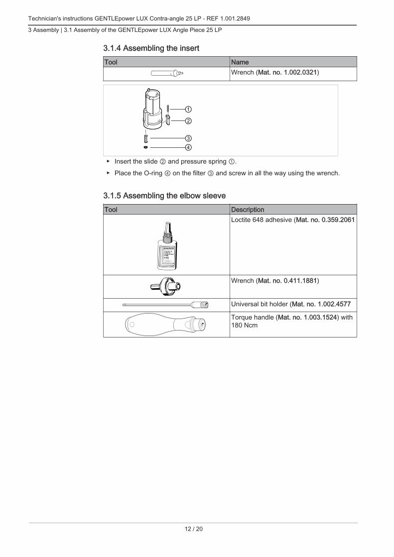
3.1.4 Assembling the insertTool Name
Wrench (Mat. no. 1.002.0321)
▶ Insert the slide ② and pressure spring ①.
▶ Place the O-ring ④ on the filter ③ and screw in all the way using the wrench.
3.1.5 Assembling the elbow sleeveTool Description
Loctite 648 adhesive (Mat. no. 0.359.2061
Wrench (Mat. no. 0.411.1881)
Universal bit holder (Mat. no. 1.002.4577
Torque handle (Mat. no. 1.003.1524) with180 Ncm

Technician's instructions GENTLEpower LUX Contra-angle 25 LP - REF 1.001.2849
3 Assembly | 3.1 Assembly of the GENTLEpower LUX Angle Piece 25 LP
Tool DescriptionLoctite 306 adhesive (Mat. no. 0.359.2044
NoteDo not glue spray pipes when gluing the fibre-optic conductor.
▶ Fit a new O-ring ① to the top of spray pipe ② and a new O-ring ① to the top ofspray pipe ③.
▶ Fit a new O-ring ⑦ to the bottom of spray pipe ② and a new O-ring ⑦ to the bot‐tom of spray pipe ③.
▶ Push the head casing ⑤ into the conical sleeve ⑧ to insert spray pipe ② andspray pipe ③ into the head casing ⑤.
▶ Insert the fibre-optic bundle ④ into the conical sleeve ⑧ and slide over spray pipe②, spray pipe ③, and head casing⑤.
▶ Apply a layer of Loctite 648 to the glued joints ⑨ on the elbow sleeve.
▶ Attach the conical sleeve ⑧ to the elbow sleeve ⑩ and wipe off any excess adhe‐sive.
▶ Carefully push the axle ⑫, bearing cartridge ⑪ and insert ⑬ all the way into theelbow sleeve ⑩.
▶ Screw the threaded ring ⑭ into the elbow sleeve ⑩ and tighten to 180 Ncm withthe wrench, the universal bit holder and the torque handle.
13 / 20

Technician's instructions GENTLEpower LUX Contra-angle 25 LP - REF 1.001.2849
3 Assembly | 3.1 Assembly of the GENTLEpower LUX Angle Piece 25 LP
14 / 20
▶ Place the contra-angle handpiece in a hot-air furnace and allow the adhesive 30minutes
to set at 120 oC.
▶ Remove the head casing ⑤ from the sleeve ⑧ again.
▶ Use Loctite 306 adhesive to fix the inside of the spray sleeve ⑧ to position ⑥ andthe fibre-optic bundle ④ making sure that the fibre-optic bundle is situated such asto be flush at the front. Remove any residual adhesive from the end of the fibre-optic bundle.
▶ Place the angle piece in a hot-air furnace and allow the adhesive to set for 30 mi‐nutes at
120 oC.
3.1.6 Assembling the headTool Description
Wrench (Mat. no. 1.001.3288)
Universal bit holder (Mat. no. 1.002.4577
Torque handle (Mat. no. 1.002.4578) with100 Ncm
Circlip pliers (Mat. no. 0.411.2421)
▶ Fit one O-ring ② in the groove on the spray insert ③ and one in the attachment ofthe spray insert ③.
▶ Insert the spring washer ④ and drive axle ⑤ into the spray insert ③.
▶ Insert the spray insert ③ into the head casing ①.
▶ Screw the cover ⑥ into the head casing ① and tighten with a torque of 100 Ncmwith the wrench, the universal bit holder and the torque handle.

Technician's instructions GENTLEpower LUX Contra-angle 25 LP - REF 1.001.2849
3 Assembly | 3.1 Assembly of the GENTLEpower LUX Angle Piece 25 LP
▶ Insert the conical spring ⑦ with the larger diameter in the direction of the pushbut‐ton ⑧ in the head casing ⑤ and push the pushbutton ⑧ down perpendicularly upto the snap-in connection.
▶ Insert the two springs ⑩ with their curvature upwards into the milled edges on theadapter ⑪.
▶ Use the circlip pliers to slide the adapter ⑪ into the head casing ①, lining up thedrilled holes for the balls at the same time.
▶ Insert the two balls ⑨ into the drilled holes for the balls in the head casing ①.
▶ Pull spray pipe ⑫ and spray pipe ⑬ out slightly and insert the head casing ① allthe way. Make sure that spray pipe ⑫ and spray pipe ⑬ are inserted all the wayinto the head casing ①.
▶ Push the head casing ① into the sleeve ⑭ until it snaps into place.
15 / 20

Technician's instructions GENTLEpower LUX Contra-angle 25 LP - REF 1.001.2849
4 Testing | 4.1 Testing the GENTLEpower LUX Angle Piece 25 LP
16 / 20
4 Testing
4.1 Testing the GENTLEpower LUX Angle Piece 25 LP
4.1.1 Test set-up
① Test device 2182 KL (Mat. no.0.411.8540)
② Leakage air hose
③ Motor hose ④ Pressure gauge (Mat. no. 1.003.1050)
⑤ Motor
4.1.2 Test instruction
NoteThe following evidence must be documented:- Customer's address and repair dates- Material number or sales number of the product- Serial number of the product- Spare parts material numbers- Name, date, signature or personnel number of repair/test engineer
Requirement- Amount of cooling air: 28 ± 4 Nl/min- Drive speed: max. 40,000 rpmThe pressures are set on the test device.
Test equipment NameTest drill (Mat. no. 0.410.1702)

Technician's instructions GENTLEpower LUX Contra-angle 25 LP - REF 1.001.2849
4 Testing | 4.1 Testing the GENTLEpower LUX Angle Piece 25 LP
Test equipment NameRetention force gauge (Mat. no.0.411.4601)
Push-button tester (Mat. no. 1.003.3571)
Spray test drill (Mat. no. 0.410.1933)
Meter tube (Mat. no. 0.411.4441)
Testing Test equipment ProcedureCheck repair documents and ID Check product markings, type and
serial number.Carry out a visual inspection Carry out a general visual inspection
of external condition.There should be no visual evidenceof damage.There should be no spots on the fi‐bre-optic bundle.
Check instrumentation connection ▪ Motor Connect the angle piece to the mo‐tor coupling and pull off. The con‐nection should be made, lock anddisconnect with ease.
Check chuck ▪ Test drill Insert the test drill into the chuckand pull out.There are no obstructions to inser‐tion and removal.
▪ Retention force gauge Use a retention force gauge tomeasure the axial retention force ofthe chuck.Axial retention force: at least 17 N
Check pushbutton ▪ Pushbutton tester Insert the pushbutton tester into thechuck system and push it as far asthe stop.The pushbutton must remain de‐pressed.
Check running characteristics ▪ Motor Run the angle piece under test con‐ditions CW and CCW with radial andaxial load.There should be no noticeable vi‐brations or running noise.Under axial load, the adapter doesnot graze the pushbutton and thepushbutton does not heat up.
17 / 20
Technician's instructions GENTLEpower LUX Contra-angle 25 LP - REF 1.001.2849
4 Testing | 4.1 Testing the GENTLEpower LUX Angle Piece 25 LP
18 / 20
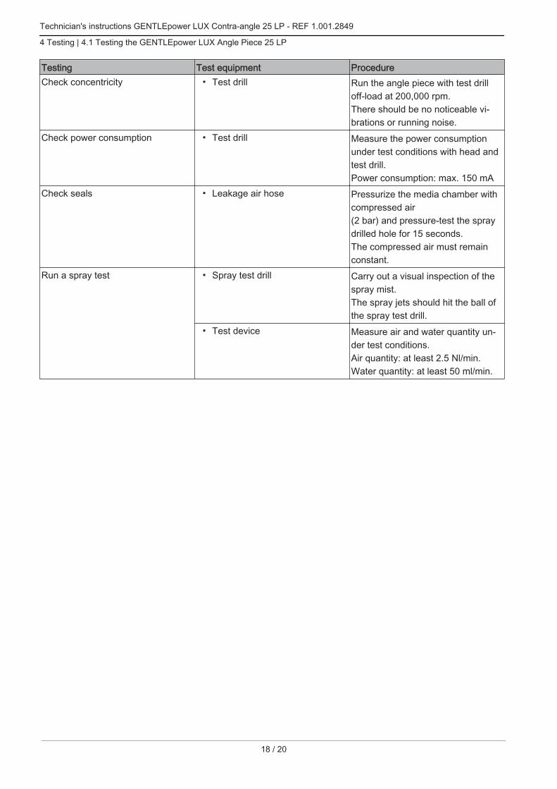
Testing Test equipment ProcedureCheck concentricity ▪ Test drill Run the angle piece with test drill
off-load at 200,000 rpm.There should be no noticeable vi‐brations or running noise.
Check power consumption ▪ Test drill Measure the power consumptionunder test conditions with head andtest drill.Power consumption: max. 150 mA
Check seals ▪ Leakage air hose Pressurize the media chamber withcompressed air(2 bar) and pressure-test the spraydrilled hole for 15 seconds.The compressed air must remainconstant.
Run a spray test ▪ Spray test drill Carry out a visual inspection of thespray mist.The spray jets should hit the ball ofthe spray test drill.
▪ Test device Measure air and water quantity un‐der test conditions.Air quantity: at least 2.5 Nl/min.Water quantity: at least 50 ml/min.


1.00
7.30
86 ·
bd ·
2016
0122
- 03
· en