Technicaltraining. Productinformation. G12Introduction
62
Technical training. Product information. BMW Service G12 Introduction
Transcript of Technicaltraining. Productinformation. G12Introduction

Technical�training.Product�information.
BMW�Service
G12�Introduction
qxf0291
ST1501

General�information
Symbols�used
The�following�symbol�is�used�in�this�document�to�facilitate�better�comprehension�or�to�draw�attentionto�very�important�information:
Contains�important�safety�information�and�information�that�needs�to�be�observed�strictly�in�order�toguarantee�the�smooth�operation�of�the�system.
Information�status�and�national-market�versions
BMW�Group�vehicles�meet�the�requirements�of�the�highest�safety�and�quality�standards.�Changesin�requirements�for�environmental�protection,�customer�benefits�and�design�render�necessarycontinuous�development�of�systems�and�components.�Consequently,�there�may�be�discrepanciesbetween�the�contents�of�this�document�and�the�vehicles�available�in�the�training�course.
This�document�basically�relates�to�the�European�version�of�left-hand�drive�vehicles.�Some�operatingelements�or�components�are�arranged�differently�in�right-hand�drive�vehicles�than�shown�in�thegraphics�in�this�document.�Further�differences�may�arise�as�the�result�of�the�equipment�specification�inspecific�markets�or�countries.
Additional�sources�of�information
Further�information�on�the�individual�topics�can�be�found�in�the�following:
• Owner's�Handbook• Integrated�Service�Technical�Application.
Contact:�[email protected]
©2015�BMW�AG,�Munich
Reprints�of�this�publication�or�its�parts�require�the�written�approval�of�BMW�AG,�Munich.
The�information�contained�in�this�document�forms�an�integral�part�of�the�technical�training�of�theBMW�Group�and�is�intended�for�the�trainer�and�participants�in�the�seminar.�Refer�to�the�latest�relevantinformation�systems�of�the�BMW�Group�for�any�changes/additions�to�the�technical�data.
Information�status:�June�2015BV-72/Technical�Training

G12�IntroductionContents1. Introduction.............................................................................................................................................................................................................................................1
1.1. History......................................................................................................................................................................................................................................11.2. Models.....................................................................................................................................................................................................................................41.3. Dimensions�and�weights............................................................................................................................................................................51.4. Silhouette�comparison..................................................................................................................................................................................61.5. Design�and�equipment..................................................................................................................................................................................7
1.5.1. Exterior..................................................................................................................................................................................................91.5.2. Interior................................................................................................................................................................................................10
2. Bodyshell.................................................................................................................................................................................................................................................112.1. Intelligent�lightweight�construction......................................................................................................................................112.2. Body�structure........................................................................................................................................................................................................13
2.2.1. Steel......................................................................................................................................................................................................132.2.2. Aluminium....................................................................................................................................................................................142.2.3. Carbon...............................................................................................................................................................................................16
3. Body�Repair�Level�1............................................................................................................................................................................................................193.1. Outer�body�skin�materials...................................................................................................................................................................193.2. Front�side�panel...................................................................................................................................................................................................203.3. Doors.....................................................................................................................................................................................................................................21
3.3.1. Front�door....................................................................................................................................................................................213.3.2. Rear�door.......................................................................................................................................................................................243.3.3. Lightweight�support....................................................................................................................................................25
3.4. Front�end.........................................................................................................................................................................................................................273.4.1. Design� ..............................................................................................................................................................................................273.4.2. "Small�Overlap"�crash�test................................................................................................................................29
3.5. Trunk......................................................................................................................................................................................................................................293.6. Light�carpet.................................................................................................................................................................................................................313.7. Panorama�glass�roof.....................................................................................................................................................................................33
3.7.1. Design................................................................................................................................................................................................333.7.2. Panorama�roof�roller�blinds..............................................................................................................................343.7.3. Drive......................................................................................................................................................................................................353.7.4. Functions.......................................................................................................................................................................................363.7.5. Notes�for�Service.............................................................................................................................................................36
3.8. Aerodynamics�measures.......................................................................................................................................................................383.8.1. Air� flaps............................................................................................................................................................................................383.8.2. Underbody�panelling..................................................................................................................................................38
4. Interior�Equipment.................................................................................................................................................................................................................394.1. Front�overview........................................................................................................................................................................................................394.2. Ambient� lighting..................................................................................................................................................................................................41

G12�IntroductionContents
4.2.1. Panorama�roof�lighting............................................................................................................................................424.3. Door�trim�panels.................................................................................................................................................................................................43
4.3.1. Speaker�lighting.................................................................................................................................................................434.3.2. Light�saber..................................................................................................................................................................................43
4.4. Seats......................................................................................................................................................................................................................................444.4.1. Front�seats..................................................................................................................................................................................444.4.2. Rear�seats....................................................................................................................................................................................494.4.3. Massage�functions........................................................................................................................................................50
4.5. Rear�console..............................................................................................................................................................................................................534.6. Roller�sunblinds....................................................................................................................................................................................................54
4.6.1. Roller�sunblind�for�rear�window.................................................................................................................544.6.2. Roller�sunblind�for�side�window................................................................................................................55
5. Luggage�Compartment.................................................................................................................................................................................................56

G12�Introduction1.�Introduction
1
The�6th�generation�of�the�BMW�7�Series�code�named�G12�is�now�being�launched�on�the�market.The�new�BMW�7�Series�is�also�a�technology�pioneer.�In�other�words,�it�features�a�host�of�newtechnologies�and�further�developed�design�elements.
The�closed�radiator�grille�and�the�precise�contours�of�the�hood�lend�the�front�of�the�new�BMW�7�Seriesa�sporty�character�at�first�glance.�The�elegant�lines�of�the�side�view�are�emphasized�by�the�distinctivedouble�crease�and�the�highlighted�Hofmeister�kink.�The�chrome�trim�strips�at�the�rear�and�the�L�shapeof�the�rear�lights�round�off�the�striking�and�confident�appearance�of�the�new�BMW�7�Series.
The�luxurious�interior�of�the�new�BMW�7�Series�is�characterized�by�the�quality�craftsmanship�at�asupreme�level,�precise�surfaces�and�a�completely�new�feeling�of�spaciousness.�This�is�complementedby�technical�highlights�such�as�Ambient�light�and�BMW�Touch�Command.�But�it�is�the�seating�comfortin�particular�that�sets�new�standards�in�this�vehicle�class.
A�particular�technical�highlight�of�the�body�is�the�body�structure�with�carbon�reinforcements.�This�isbased�on�technology�transfer�from�development�of�the�BMW�i�vehicles.�Use�of�carbon�with�its�specificmaterial�properties�increases�torsional�rigidity�and�strength.�The�weight�is�reduced�at�the�same�time.
1.1.�HistoryE23
E23
The�E23�is�the�first�BMW�7�Series�and�was�produced�from�1977�to�1986.
The�passenger�cell�has�a�dynamic�appearance�due�to�the�pronounced�slope�of�the�A-pillar�and�smoothroofline�transition�to�the�rear.�This�lends�the�E23�a�sporty�yet�elegant�look.
In�the�interior,�the�instrument�panel�is�turned�towards�the�driver,�making�the�operating�elements�easierto�reach.�This�ergonomically�optimum�driver�orientation�has�become�a�design�feature�that�is�typical�forBMW.
The�E23�was�initially�produced�in�the�works�in�Munich�and�Dingolfing.�As�from�December�1982,the�E23 rolled�off�the�assembly�line�only�in�Dingolfing,�like�all�subsequent�BMW�7�series�models.

G12�Introduction1.�Introduction
2
E32
E32
The�E32�was�produced�from�1986�to�1994.
The�harmonious�contours�and�flowing�transitions�at�the�front,�side�and�rear�provide�the�E32�with�aparticularly�elegant�look.�The�horizontally�wider�radiator�grill�reinforces�the�presence�of�the�front�end.The�L-shaped�rear�lights�form�the�basis�of�an�important�BMW�design�element.
The�E32�was�also�the�first�BMW�7�Series�to�be�offered�as�a�long�version –�with�a�11.4 cm�/�4.5�inchlonger�body.
E38
E38
The�E38�was�produced�from�1994�to�2001.
Thanks�to�its�elegant�lines,�the�3rd�generation�of�the�BMW�7�Series�has�a�more�elegant�and�elongatedappearance�than�its�predecessor.
Particular�attention�is�paid�to�the�rear�seat�passengers�through�a�host�of�equipment�and�design�details.
In�addition�to�the�"normal"�long�version�(wheelbase�extended�by�14 cm�/�5.5�inches),�the�E38�was�alsoproduced�in�a�version�with�a�39 cm�/�15.3�inch-longer�wheelbase�as�the�“L7”.

G12�Introduction1.�Introduction
3
E65/E66
E65
The�E65�was�produced�from�2001�to�2008�(LCI:�2005�to�2008).
BMW�opened�up�a�completely�new�design�era�with�the�E65.�The�front�end�preserves�the�typical�BMWradiator�grille�and�twin�circular�headlights.�The�front�headlights�extend�elegantly�into�the�side�contours.The�side�contour�exudes�calm�and�elegance�thanks�to�the�single�continuous�line�extending�from�thefront�through�to�the�complete�rear�end.�The�roofline�has�a�Coupé-like�form.
The�greatest�revolution�in�the�vehicle�interior�is�the�iDrive�operating�system.�This�system�made�itpossible�to�dispense�with�a�large�number�of�buttons,�making�the�driving�area�appear�much�tidierand�clearer.
The�E66�is�the�long�version�of�the�E65�and�was�therefore�given�its�own�development�codefor�the�first�time.
F01/F02
F01
The�F01/F02�was�produced�from�2008�to�2015�(LCI:�from�2012).
The�5th�generation�of�the�BMW�7�Series�creates�an�even�stronger�presence�through�its�large�air�inletsand�long�hood.�At�the�sides,�the�balanced�proportions�are�elegantly�extended�by�longitudinal�lines�andsurfaces.�The�width�of�the�rear�area�is�emphasized�to�convey�the�vehicle's�sporting�character.

G12�Introduction1.�Introduction
4
A�special�feature�in�the�vehicle�interior�is�the�so-called�“Black�Panel“�in�the�instrument�panel.The�displays�and�indicator�lights�in�the�instrument�cluster�are�now�located�behind�a�matt-blackpanel�and�are�no�longer�visible�when�switched�off.
1.2.�ModelsG12
G12
The�new�BMW�7�Series�has�the�development�code�G12�(long�version).�The�market�introduction�willstart�in�October�2015.
The�following�models�will�be�available�for�the�market�introduction:
G12 Drive Displacementin�cm3
Power�in�kW�(HP) Torque�inNm�(lb-ft)
740i 6-cylinder�gasolineengine
2998 240�(320)�from5500 rpm
450�(330)�from1380�rpm
750Li2 8-cylinder�gasolineengine
4395 330�(445)�from5500 rpm
650�(480)�from1500�rpm
2Also�available�as�xDrive
The�mounting�points�for�lifting�the�G12�are�much�further�apart�in�the�longitudinal�direction�of�thevehicle�than�on�the�F02.�For�this�reason,�particular�attention�must�be�paid�to�ensuring�that�the�vehiclehoist�in�question�is�suitable�for�lifting�the�G12.
• F02�distance�of�mounting�points�in�longitudinal�direction:�1690 mm�/�66.5�inches.• G12�distance�of�mounting�points�in�longitudinal�direction:�2073 mm�/�81.6�inches.

G12�Introduction1.�Introduction
5
1.3.�Dimensions�and�weightsBelow�you�can�see�the�outer�dimensions�of�the�G12�in�the�BMW�740i:
The�G11�is�not�available�in�the�US�market.
G11�Not�For�US/G12�outer�dimensions
Index Explanation G12a Vehicle�height,�empty [mm] 1479b Front�track�width,�basic�wheels [mm] 1612c Front�overhang [mm] 890d Wheelbase [mm] 3210e Rear�overhang [mm] 1148f Rear�track�width,�basic�wheels [mm] 1650g Vehicle�length [mm] 5248h Vehicle�width�without�exterior
mirrors�(vehicle�width�withexterior�mirrors)
[mm] 1902(2169)

G12�Introduction1.�Introduction
6
Below�you�can�see�the�US�vehicle�curb�weights�and�the�payloads�of�the�G12�using�the�example�of�theBMW�740i�and�750i�xDrive:
Model Curb�weightRear-
wheel�drive
Curb�weightxDrive
PayloadcapacityRear-
wheel�drive
PayloadcapacityxDrive
740i [kg/lbs] 1916/4225 N/A 438/960 N/A750i [kg/lbs] N/A 2091/4610 438/960 438/960
1.4.�Silhouette�comparisonThe�G12�to�F02.
G12�dimensions
G12 F02�LCIVehicle�height,�empty [mm] 1479 1481Front�overhang [mm] 880 866Wheelbase [mm] 3210 3210Rear�overhang [mm] 1148 1143Vehicle�length [mm] 5238 5219

G12�Introduction1.�Introduction
7
1.5.�Design�and�equipment
G12�exterior�highlights
Index Explanation1 Air�vents�on�radiator�grille2 Chrome�trim�strip�on�Air�Breather3 Continuous�trim�strip�on�window�cavity/door�frame4 Continuous�rear�trim�strip5 Integrated�exhaust�tailpipes6 Light�carpet

G12�Introduction1.�Introduction
8
G12�Interior�highlights
Index Explanation1 Central�Information�Display�with�touch�operation2 Interior�fragrance3 Camera�for�gesture�control�detection4 Captain's�chair5 BMW�Touch�Command6 Light�saber7 Panorama�roof�lighting�“Sky�Lounge”

G12�Introduction1.�Introduction
9
1.5.1.�Exterior
G12�Exterior�trim
Index ExplanationA Exterior�trim�on�basic�versionB Exterior�trim�optional�equipment
The�basic�version�of�the�G12�already�features�a�large�number�of�chrome�strips.�The�ornamentalgrille�and�the�air�flaps�are�finished�in�high-gloss�Black�and�have�chrome�trims�on�the�front�surfaces.A�chrome�strip�is�fitted�in�each�case�above�and�below�the�bottom�air�inlets�on�the�right�and�left.
Like�on�the�F01/F02,�the�G12�also�features�tailpipes�integrated�in�the�body.�These�have�a�model-dependent�design�and�are�surrounded�by�a�chrome�frame.�There�is�a�further�chrome�strip�in�each�casenext�to�the�reflectors�in�the�rear�bumper.�The�continuous�chrome�strip�on�the�trunk�is�continued�in�therear�lights.

G12�Introduction1.�Introduction
10
1.5.2.�InteriorThe�basic�version�of�the�interior�equipment�already�has�a�high�level�of�quality.�The�leather�used�in�theinterior�is�Dakota�leather,�which�is�available�in�different�colors.
The�following�components�are�covered�with�leather�in�the�basic�version:
• Seat�surfaces• Upholstery�insert�on�headrests• Front�and�rear�center�armrests• Armrests�on�the�door�trim�panels
G12�Nappa�exclusive�leather
In�the�equipment�specification�Nappa�leather�with�extended�contents,�additional�seat�and�door�trimpanel�components�are�covered�with�leather.
In�this�equipment�specification,�the�leather�features�elaborate�diamond�stitching�in�the�area�of�thecenter�seat�surfaces�and�backrests�as�well�as�on�the�backrest�upper�section.�The�leather�of�the�seatsurfaces�and�backrests�is�perforated�in�combination�with�the�equipment�“active�seat�ventilation”.The�equipment�“Exclusive�leather�Nappa�with�extended�content”�is�available�only�in�combination�withcomfort�seats.

G12�Introduction2.�Bodyshell
11
2.1.�Intelligent�lightweight�construction
G12�material�concept�for�body�structure
Index Explanationa Ultra-high-strength�hot-formed�steelsb Multiphase�steelsc Aluminiumd Carbone Other�steels
The�bodyshell�of�the�G12�was�designed�completely�as�a�lightweight�construction.�The�focus�here�ison�the�body�structure�as�a�so-called�carbon�core.�In�addition�to�the�components�made�of�steel�andaluminium,�this�also�features�numerous�reinforcements�made�of�carbon.�The�different�materials�areused�so�that�their�specific�characteristics�optimally�complement�each�other.�As�a�result,�it�is�above�allthe�material�mix�that�ensures�a�low�weight�in�combination�with�high�crash�safety.
Thanks�to�the�intelligent�material�mix,�it�was�possible�to�reduce�the�weight�of�the�body�structure�byapproximately�40�kg�/�88�lbs�compared�with�the�F02.

G12�Introduction2.�Bodyshell
12
G12�Side�frame�structure
Index Explanationa Ultra-high-strength�steel�(> 900 N/mm²)b Multiphase�steel�(> 300�N/mm²)c Aluminiumd Carbone Deep-drawing�steel�(<�300 N/mm²)f Other�steel�grades1 Inner�roof�frame2 Roof�frame�reinforcement3 C-pillar�reinforcement4 Outer�side�frame�(deep-drawing�steel)5 Reinforcement�plate,�B-pillar6 Side�sill�reinforcement�plate7 Side�sill�reinforcement8 Inner�side�frame9 B-pillar�reinforcement
The�body�structure�of�the�G12�is�made�of�steel,�aluminium�and�carbon�components.�Through�theconsistent�use�of�high-strength�and�ultra-high-strength�steels�and�high-strength�aluminium�alloys,it�was�possible�to�increase�the�overall�minimum�proof�stress�of�all�metal�materials�in�the�bodyshellcompared�with�the�predecessor.�An�additional�weight�reduction�was�achieved�by�the�use�of�carbon.

G12�Introduction2.�Bodyshell
13
The�side�frame�of�the�G12�comprises�a�three-piece�frame:
• Outer�side�frameThe�outer�side�frame�is�made�of�deep-drawing�steel.
• Middle�side�frameThe�middle�side�frame�is�made�of�a�material�mix�comprising�ultra-high-strengthheat-formed�steel�and�carbon.�This�combination�means�that�the�middle�sideframe�is�optimized�both�in�terms�of�weight�and�rigidity.
• Inner�side�frameThe�inner�side�frame�is�made�of�high-strength�and�ultra-high-strength�steel�grades.
2.2.�Body�structureThe�information�in�this�chapter�shows�the�body�structure�of�the�G12.
2.2.1.�Steel
G12�Ultra-high-strength�steels�in�the�body�structure

G12�Introduction2.�Bodyshell
14
Index Explanation1 Carrier�support,�bulkhead2 Inner�side�frame3 Engine�support�extension4 Reinforcement�plate,�B-pillar5 Side�sill�reinforcement�plate6 Outer�connecting�plate
The�body�structure�consists�largely�of�high-strength�and�ultra-high-strength�steel�grades.�The�shareof�ultra-high-strength�heat-formed�steel�grades�is�particularly�high.
An�example�of�this�is�the�B-pillar�reinforcement�plate.�This�is�made�from�a�tailored�rolled�blank.This�made�it�possible�to�achieve�an�additional�reduction�in�weight.
Further�information�on�the�steel�grades�used�for�body�construction�can�be�found�in�the�informationbulletin�“Fundamentals�of�Steel”.
2.2.2.�Aluminium
G12�Aluminium�in�the�body�structure

G12�Introduction2.�Bodyshell
15
Index Explanation1 Front�spring�strut�dome2 Rear�spring�strut�dome3 Side�member4 Engine�support
The�use�of�aluminium�extruded�profiles�and�complex�die-cast�aluminium�parts�permits�realization�ofhigh�body�rigidity�in�combination�with�low�weight.�All�requirements�relating�to�passive�safety�are�alsomet.
The�spring�strut�domes�at�the�front�and,�also�for�the�first�time,�at�the�rear�are�manufactured�usingthe�aluminium�pressure�die�casting�process.�New�aluminium�cast�alloys�were�developed�in�order�toincrease�the�crash�safety�of�these�components.�These�alloys�are�characterized�above�all�by�improvedcrash�performance.
Screw�connections
G12�Screw�connection�of�engine�support/bulkhead
Index Explanation1 Engine�support2 Engine�support�connection3 Flow�drill�screw�(new�mounting�style)
Some�of�the�aluminium-steel�connections�in�the�G12�body�structure�are�produced�using�the�new�bodyjoining�technique�of�flow�drill�screws.�These�include,�for�example�the�connection�between�the�enginesupport�(aluminium�extruded�profile)�and�the�bulkhead�carrier�support�(ultra-high-strength�hot-formedsteel).

G12�Introduction2.�Bodyshell
16
Flow�drill�screws�are�driven�directly�into�the�superposed�sheets.�When�this�happens,�the�speciallyshaped�tip�produces�a�flow�hole�and�a�thread�is�then�cut.�This�joining�technique�is�used�exclusivelyin�production.
When�a�flow�drill�screw�connection�has�been�undone,�it�must�not�be�joined�again�by�meansof�flow�drill�screws.�This�could�lead�to�a�considerable�reduction�in�strength.
In�the�event�of�a�repair�according�to�body�repair�level�2�and�3,�the�flow�drill�screws�are�replacedby�blind�rivets.
2.2.3.�Carbon
G12�Carbon�in�the�body�structure

G12�Introduction2.�Bodyshell
17
Index Explanation1 Roof�bow�(bonded,�riveted)2 B-pillar�reinforcement�(bonded)3 Side�frame�reinforcement�(bonded)4 Transmission�tunnel�reinforcement�(bonded)5 C-pillar�reinforcement�(bonded,�riveted)6 Storage�shelf�(bonded�and�clipped)7 Side�sill�reinforcement�(bonded)
The�body�structure�of�the�G12�is�reinforced�in�many�areas�by�carbon�components.�This�makes�the�G12the�first�large-series�vehicle�in�the�world�in�which�carbon�is�used�in�the�passenger�safety�cell.
Roof�bow
Roof�bow
Index Explanation1 Roof�bow�made�of�carbon2 Connection�of�side�frame�made�of�steel

G12�Introduction2.�Bodyshell
18
Some�roof�bows�are�made�of�a�steel-carbon�composite.�This�allows�simple�assembly�in�production
Rear�window�shelf
G12�Storage�shelf
Index Explanation1 Plastic�clip2 Storage�shelf�made�of�carbon
The�storage�shelf�of�the�G12�is�made�of�carbon�and�is�bonded�and�clipped�together�with�the�bodystructure.�The�clip�connection�is�achieved�by�means�of�Lego-Fit�(Ball�socket).�This�is�a�type�of�pressstud�joining�method�which�is�used�in�production�to�fix�the�storage�shelf�in�position.�Lego-Fit�(Ballsocket)�connections�consist�of�a�steel�ball�integrated�in�the�body�on�the�one�side�and�a�plastic�clipon�the�opposite�side.

G12�Introduction3.�Body�Repair�Level�1
19
Taking�into�account�the�repair�stages�of�the�workshop�information�system�of�BMW,�the�body�repairwork�in�the�technical�training�is�divided�into�three�repair�levels.�Each�of�the�three�Body�Repair�Levelsincludes�certain�prerequisites�for�the�training�of�the�employees�and�for�the�workshop�equipment.
The�special�characteristics�of�the�add-on�body�parts�and�the�materials�used�in�the�outer�body�skin�aredescribed�in�this�chapter.�However,�the�basic�functions�of�the�roof�and�the�outer�body�skin�componentsmade�of�plastic�are�the�same�as�on�other�current�BMW�models.�For�this�reason,�these�components�willnot�be�described�in�detail�here.
3.1.�Outer�body�skin�materials
G12�outer�body�skin
Index Explanation1 Other�steel�grades2 Aluminium3 Plastic4 Deep-drawing�steel
As�on�the�predecessor�F01/F02,�the�roof,�doors,�hood�and�front�fenders�are�made�of�aluminium.The�G12�trunk�lid�is�also�made�of�aluminium.
The�bumper�panels�at�front�and�rear�as�well�as�the�side�sills�are�made�of�plastic�(PP + EPDM)�as�before.However,�further�development�of�this�material�made�it�possible�to�reduce�the�density�and�weight.

G12�Introduction3.�Body�Repair�Level�1
20
3.2.�Front�side�panel
G12�Front�side�panel
Index ExplanationA Air�Breather�mounting1 Front�left�side�panel2 Air�Breather�trim3 Expanding�rivet4 Trim�mounting�clips5 Air�duct

G12�Introduction3.�Body�Repair�Level�1
21
The�Air�Breather�installed�for�the�first�time�in�the�F34�is�provided�with�chrome�trim�in�the�G12.This�is�fitted�from�the�front�in�X-direction�and�locked�in�position�at�the�rear�in�Y-direction�by4�metal�clips.�The�air�duct�is�attached�to�the�front�side�panel�by�means�of�expanding�rivets.
3.3.�Doors
3.3.1.�Front�door
G12�Driver's�door�structure

G12�Introduction3.�Body�Repair�Level�1
22
Index Explanation1 Side�window�in�driver's�door2 Door�structure3 Door�outer�skin4 Door�lock5 Outer�door�handle�mechanism6 Rotary�striker�lock7 Automatic�Soft�Close�system8 Side�impact�protection9 Door�stop10 Lightweight�support11 Coil�spring12 Retaining�strap13 Set�screw14 Sliding�element
The�front�and�rear�doors�essentially�have�the�same�structure.�The�descriptions�in�this�chapter�refer�tothe�driver's�door.
Like�on�the�predecessor,�the�doors�of�the�G12�have�an�aluminium�shell�design.�The�aluminiumsupporting�structure�is�connected�with�the�aluminium�outer�skin�by�innovative�laser�weldingtechnology.
The�stepless�door�stop�holds�the�door�in�any�position.�The�moment�of�friction�required�for�this�isproduced�by�2�set�screws�which�are�tensioned�at�the�sides�against�the�retaining�strap.�The�set�screwsare�adjusted�in�production�and�cannot�then�be�adjusted�again.�In�addition,�2�spring-loaded�slidingelements�hold�the�door�in�defined�detent�positions�when�the�vehicle�is�inclined.�These�positions�aredetermined�by�the�geometry�of�the�retaining�strap.�The�compact�design�of�the�door�stop�makes�itpossible�to�achieve�a�weight�saving�for�all�door�stops�of�approx.�2.5�kg�/�5.5�lbs�compared�with�the�doorstops�on�F01/F02.
The�door�lock�optionally�features�automatic�soft-close.�Emergency�operation�is�possible�via�theintegrated�lock�cylinder.
The�side�impact�protection�is�made�of�high-strength�steel.

G12�Introduction3.�Body�Repair�Level�1
23
G12�Trim�strips�on�front�door
Index Explanation1 Trim�strip�on�window�frame2 Cavity�trim3 Trip�strip�on�mirror�body4 Trim�strip�on�mirror�base5 Bottom�trip�strip6 Mounting�clips7 Mounting�clips

G12�Introduction3.�Body�Repair�Level�1
24
3.3.2.�Rear�door
G12�Rear�door�mountings
Index Explanation1 Trim�strip�mounting�on�window�frame2 Quarter�glass�mounting3 Bottom�trip�strip4 Mounting�clips
A�special�feature�of�the�rear�doors�is�the�one-piece�design�of�the�cavity�strip�and�window�frame�trimstrip.�This�is�secured�by�means�of�2�screws�in�the�area�of�the�Hofmeister�kink.�The�other�trim�strip�islocked�in�position�as�before.�The�quarter�glass�is�screwed�into�place�like�on�the�F01/F02.

G12�Introduction3.�Body�Repair�Level�1
25
When�tightening�the�screws,�the�tightening�torque�specified�in�the�ISTA�workshop�information�systemmust�be�observed�exactly.
3.3.3.�Lightweight�support
G12�Lightweight�support�for�driver's�door

G12�Introduction3.�Body�Repair�Level�1
26
Index Explanation1 Side�window�latch�mechanism2 Bayonet�fitting3 Driver's�door�airbag�pressure�sensor4 Driver's�door�speaker5 Power�window�mechanism6 Lightweight�support7 Power�window�motor
The�lightweight�supports�of�the�front�and�rear�doors�have�essentially�the�same�design.The�descriptions�in�this�chapter�refer�to�the�lightweight�support�for�the�driver's�door.
The�lightweight�support�is�mounted�on�the�door�structure�by�means�of�screws�and�bayonet�fittings.It�divides�the�interior�of�the�door�into�a�dry�side�and�a�wet�side.�The�dry�side�is�closed�off�to�the�insideby�the�door�trim�panel�and�the�wet�side�is�closed�towards�the�outside�by�the�door�outer�skin.�Sensitivecomponents –�such�as�speakers,�airbag�sensors�and�electric�drives�–�are�located�on�the�dry�side�andare�protected�against�moisture.
The�power�window�mechanism�is�based�on�a�cable�mechanism.�The�electrical�drive�force�is�providedby�an�electric�motor�installed�on�the�dry�side�of�the�lightweight�support.
The�door�airbag�sensors�must�not�be�cleaned�with�compressed�air�otherwise�they�will�be�destroyed.
The�seals�of�the�lightweight�supports�must�not�be�damaged�in�order�to�guarantee�proper�functioningof�the�airbag�sensors�in�the�doors.
G12�Introduction3.�Body�Repair�Level�1
27
3.4.�Front�end
3.4.1.�Design
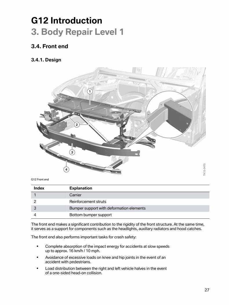
G12�Front�end
Index Explanation1 Carrier2 Reinforcement�struts3 Bumper�support�with�deformation�elements4 Bottom�bumper�support
The�front�end�makes�a�significant�contribution�to�the�rigidity�of�the�front�structure.�At�the�same�time,it�serves�as�a�support�for�components�such�as�the�headlights,�auxiliary�radiators�and�hood�catches.
The�front�end�also�performs�important�tasks�for�crash�safety:
• Complete�absorption�of�the�impact�energy�for�accidents�at�slow�speedsup�to�approx.�16�km/h�/�10�mph.
• Avoidance�of�excessive�loads�on�knee�and�hip�joints�in�the�event�of�anaccident�with�pedestrians.
• Load�distribution�between�the�right�and�left�vehicle�halves�in�the�eventof�a�one-sided�head-on�collision.

G12�Introduction3.�Body�Repair�Level�1
28
In�the�G12,�it�has�been�possible�to�successfully�meet�the�increased�requirements�for�crash�safety�inspite�of�a�weight�reduction�of�the�front�end�compared�with�the�F01/F02.�This�was�achieved�mainlythrough�the�use�of�high-strength�aluminium.�A�further�reason�is�the�one-piece�design�of�the�bumpersupport�and�deformation�elements.�The�use�of�welded�connections�instead�of�screw�connectionssaves�weight�and�at�the�same�time�increases�rigidity.
Additional�US�version�components
Additional�G12�Front�end�components
Index Explanation1 Additional�struts2 Crash�frame3 Tensioning�strap�for�carrier�support4 Front�tensioning�straps
US�version�vehicles�must�pass�an�additional�crash�test,�the�small�overlap�test,�for�the�purpose�ofoptimum�insurance�classification.
The�small�overlap�in�the�"Small�overlap�test"�means�that�there�is,�in�principle,�a�risk�that�the�front�wheelwill�damage�the�bulkhead.�This�is�avoided�in�the�G12�in�US�version�by�additional�components�in�thefront�end.
In�the�event�of�a�corresponding�head-on�collision,�the�crash�frame�is�pressed�against�the�front�wheel.As�a�result,�the�rim�is�guided�so�that�the�wheel�is�prevented�from�turning�in.�The�tensioning�strapsstabilize�the�position�of�the�respective�crash�frame.

G12�Introduction3.�Body�Repair�Level�1
29
3.4.2.�"Small�Overlap"�crash�test
Crash�test�comparison�US-IIHS
Index ExplanationA “Small�Overlap”�crash�test�with�rigid�barrier�and�an�overlap�of�25 %�(IIHS*)B “Head-on�collision�crash�test”�with�honeycomb�barrier�and�an�overlap
of�40 %�(EURO-NCAP)�Not�US
*IIHS:�Insurance�Institute�for�Highway�Safety.
In�the�"Small�Overlap"�test,�the�vehicle�is�driven�against�a�rigid�barrier�at�a�speed�of�64�km/h�/�40�mph.The�overlap�is�only�25�%�so�that�the�impact�energy�cannot�be�transferred�into�the�body�structuredirectly�via�the�engine�support.�Instead,�the�load�path�is�via�the�front�wheel�to�the�side�sill�and�via�thebulkhead�carrier�support�to�the�side�frame.
3.5.�Trunk
G12�Overview�of�Trunk

G12�Introduction3.�Body�Repair�Level�1
30
Index Explanation1 Tension�spring�(without�damping�element)2 Trunk�hinge3 Electric�spindle�drive4 Plug�connector�for�spindle�drive5 Emergency�release6 Trunk�lock7 Electric�motor�for�automatic�soft-close�system
The�trunk�of�the�G12�is�made�completely�of�aluminium�for�the�first�time.�This�made�it�possible�torealize�a�weight�saving�of�approx.�5.5�kg�/�12�lbs�compared�with�the�trunk�of�the�F02.�The�outer�skincomponents�area�connected�with�each�other�by�means�of�laser�weld�seams.
The�G12�is�equipped�as�standard�with�automatic�trunk�operation.�The�trunk�is�opened�and�closed�bymeans�of�a�spindle�drive.�Whereas�other�current�BMW�vehicles�are�equipped�with�one�spindle�driveeach�on�the�right�and�left�sides,�the�G12�has�a�single�spindle�drive�on�the�right�side.
The�following�actuation�options�are�available�for�the�trunk,�depending�on�the�vehicle�equipment:
Opening CloseOuter�Trunk�button X XInner�Trunk�button XRemote�key/ID�transmitter XButton�in�driver's�door X XContactless�via�sensors�in�the�bumper X XEmergency�release�via�handle�in�the�luggagecompartment
X
The�trunk�trim�panel�is�made�largely�of�kenaf.�This�is�a�natural�fiber�material�that�is�already�successfullyused�in�the�door�trim�panels�of�the�BMW�i3.�Kenaf�is�characterized�above�all�by�its�low�weight�andenvironmental�friendliness.�The�visible�surface�of�the�trunk�trim�panel�is�made�of�black�velour.

G12�Introduction3.�Body�Repair�Level�1
31
3.6.�Light�carpet
G11�Light�carpet
The�light�carpet�is�a�graphic�projection�in�the�entrance�and�exit�area�on�the�driver's�and�passenger'ssides.�It�is�standard�for�the�G12.�For�more�information�about�the�light�carpet,�refer�to�the�“GeneralVehicle�Electronics”�section�of�this�reference�manual.

G12�Introduction3.�Body�Repair�Level�1
32
G12�Light�carpet�adjustment
Index Explanation1 Adjusting�screw
The�light�sources�are�located�in�the�front�area�of�the�side�sills.�The�light�carpet�is�adjusted�by�means�ofan�adjusting�screw�in�each�case.�For�this�purpose,�the�light�source�can�be�continuously�activated�usingthe�ISTA�workshop�information�system.
The�light�carpet�is�adjusted�to�a�certain�length�between�the�start�of�the�first�projection�line�and�the�endof�the�last�projection�line.�Attention�must�also�always�be�paid�to�the�symmetry�between�the�left�andright�vehicle�sides.

G12�Introduction3.�Body�Repair�Level�1
33
3.7.�Panorama�glass�roof
3.7.1.�Design
G12�panorama�glass�roof

G12�Introduction3.�Body�Repair�Level�1
34
Index Explanation1 Glass�slide/tilt�sunroof�panel,�front2 Rear�glass�slide/tilt�sunroof�panel3 Adjusting�screw�for�rear�glass�slide/tilt�sunroof�panel4 Rear�panorama�roof�roller�blind5 Gasket6 Panorama�glass�roof�frame7 Wind�deflector8 Tilt�mechanism,�front�glass�slide/tilt�sunroof�panel9 Front�panorama�roof�roller�blind
The�standard�equipment�for�the�G12�is�the�a�panorama�glass�roof.�Compared�with�the�conventionalglass�slide/tilt�sunroof,�the�panorama�glass�roof�offers�an�improved�feeling�of�spaciousness�for�therear�seat�passengers.
The�front�glass�slide/tilt�sunroof�panel�can�be�moved�externally�over�the�rear�glass�panel.�The�rearglass�slide/tilt�sunroof�panel�is�fixed�and�contributes�to�the�rigidity�of�the�body�as�a�thrust�surface.
The�panorama�glass�roof�is�installed�from�inside.�This�makes�it�possible�to�omit�trim�elements�in�theedge�area�of�the�roof�and�a�harmonious�overall�appearance�is�produced.�The�rear�glass�panel�as�anaperture�to�permit�optimum�positioning�of�the�roof-mounted�aerial.
3.7.2.�Panorama�roof�roller�blindsAs�sun�protection�and�noise�insulation,�the�panorama�glass�roof�has�2�panorama�roof�roller�blinds,one�each�for�the�front�and�rear�roofliner�cutouts.�These�are�available�in�different�materials�and�colors.
Operation�is�performed�via�the�roof�function�center,�the�buttons�in�the�rear�doors�or�BMW�TouchCommand.
The�panorama�roof�roller�blinds�can�be�opened�and�closed�seamlessly�and�independently�of�eachother.�An�anti-trap�mechanism�is�active�during�automatic�closing.

G12�Introduction3.�Body�Repair�Level�1
35
3.7.3.�Drive
G12�Panorama�glass�roof�frame
Index Explanation1 Panorama�glass�roof�frame2 Plug�connector�for�panorama�roof�roller�blinds3 Drive�unit�for�rear�panorama�roof�roller�blind4 Drive�unit�for�front�panorama�roof�roller�blind5 Contacts�for�panorama�roof�lighting6 Drive�unit�for�front�glass�slide/tilt�sunroof�panel
The�front�glass�slide/tilt�sunroof�panel�and�panorama�roof�roller�blinds�are�driven�by�electric�motors.The�drive�forces�are�transmitted�to�the�cassette�in�the�guide�rails�by�means�of�cables.
The�electric�contacts�of�the�panorama�roof�lighting�which�is�option�407�(see�interior�equipment)�of�thefront�glass�slide/tilt�sunroof�panel�are�located�on�the�right�and�left�in�the�front�area�of�the�panoramaglass�roof�frame.

G12�Introduction3.�Body�Repair�Level�1
36
3.7.4.�FunctionsThe�panorama�glass�roof�and�panorama�roof�roller�blinds�have�the�following�additional�functions:
• Rain�closingIf�the�G12�is�parked�with�open�panorama�glass�roof�and�the�rain-light-solar-condensationsensor�detects�rain,�the�front�glass�slide/tilt�sunroof�panel�closes�to�the�vent�position.
• Parking�functionsIf�the�G12�is�parked�with�open�panorama�glass�roof,�the�panorama�glass�roof�will�automaticallymove�to�vent�position�after�6�hours.When�the�vehicle�is�locked,�the�rear�panorama�roof�roller�blind�is�closed�in�order�to�preventpossible�heating�up�of�the�rear�seats�and�the�BMW�Touch�Command�due�to�solar�radiation.When�the�vehicle�is�unlocked,�the�rear�panorama�roof�roller�blind�is�automatically�moved�tothe�position�it�was�in�before�locking.
• Convenient�closing/convenient�openingThe�front�glass�slide/tilt�sunroof�panel�and�the�panorama�roof�roller�blind�can�be�opened�andclosed�via�the�ID�transmitter.
• Crash�risk�closingIn�case�of�an�accident,�the�front�glass�slide/tilt�sunroof�panel�and�the�front�panorama�roof�rollerblind�are�automatically�closed.
3.7.5.�Notes�for�Service
Initialization
Initialization�is�frequently�necessary�after�working�on�the�panorama�glass�roof�or�panorama�roof�rollerblinds.�This�can�be�recognized�by�the�fact�that�automatic�opening�or�closing�of�the�panorama�glassroof�is�not�possible.
A�function�check�must�be�performed�after�initialization.
No�anti-trap�function�is�available�during�initialization.
The�procedure�described�in�the�ISTA�workshop�information�system�must�always�be�observed.
Emergency�operation
Emergency�operation�of�the�front�glass�slide/tilt�sunroof�panel�is�possible�at�the�front�drive�unit�usinga�hexagon�socket�wrench.
G12�Introduction3.�Body�Repair�Level�1
37
Installation�and�adjusting�procedures
The�components�of�the�panorama�glass�roof�can�normally�be�replaced�individually.�It�is�necessaryto�pay�attention�to�a�number�of�special�points�to�note�for�exchange�as�well�as�installation�anddisassembly.
• RemovalRemoval�of�the�panorama�glass�roof�in�the�workshop�should�be�performed�by�at�least�2employees.�Since�the�rear�glass�slide/tilt�sunroof�panel�is�secured�and�adjusted�individually,it�should�also�be�transported�individually.�The�panorama�glass�roof�frame�must�not�be�lifted�atthe�two�front�and�rear�ends.�Otherwise,�this�may�result�in�a�kink�in�the�middle�part�of�the�frame.
• AssemblyThe�entire�installation�procedure�for�the�panorama�glass�roof�is�performed�from�the�vehicleinterior.�The�rear�glass�slide/tilt�sunroof�panel�is�installed�first�and�then�the�panorama�glassframe�together�with�front�glass�slide/tilt�sunroof�panel.�The�front�glass�slide/tilt�sunroof�panelmust�be�moved�to�vent�position�before�installation.�A�specific�sequence�must�be�observedwhen�tightening�the�mounting�bolts�of�the�rear�glass�slide/tilt�sunroof�panel�and�the�panoramaglass�roof�frame.�Leaks�can�occur�if�this�sequence�is�not�observed.�Disassembly�takes�place�inreverse�order.
• SettingThe�rear�glass�slide/tilt�sunroof�panel�is�supplied�pre-adjusted.�Nevertheless,�fine�adjustmentis�necessary�in�some�cases.�This�is�performed�in�Z-direction�by�means�of�5�adjusting�screws.After�installation�of�the�panorama�glass�roof�frame,�the�front�glass�slide/tilt�sunroof�panelis�adjusted�by�means�of�its�6�mounting�bolts.�The�trim�covers�inserted�at�the�side�must�beremoved�for�adjustment�with�installed�roofliner.
The�current�procedures�in�the�workshop�information�system�must�be�observed�for�all�work�on�thepanorama�glass�roof.

G12�Introduction3.�Body�Repair�Level�1
38
3.8.�Aerodynamics�measures
3.8.1.�Air�flaps
G12�Air�flaps
Index ExplanationA Top�air�flaps�completely�openB Top�air�flaps�completely�closed
A�new�generation�of�automatic�air�flap�control�is�used�in�the�G12.�The�air�flaps�are�located�at�the�topwithin�the�ornamental�grille�surround�(radiator�grilles)�and�behind�the�air�inlets�of�the�bumper�panel.
The�top�air�flaps�are�integrated�in�the�front�ornamental�grille�for�the�first�time�and�are�thus�located�inthe�direct�field�of�view.
The�top�and�bottom�air�flaps�are�controlled�via�separate�actuators.�When�a�corresponding�coolingrequest�is�received,�the�bottom�air�flaps�always�open�first�and�then�the�top�air�flaps.�The�bottom�airflaps�can�also�move�to�several�intermediate�positions.�The�air�flaps�are�activated�briefly�when�theignition�is�switched�on.
3.8.2.�Underbody�panellingIn�comparison�with�the�F01/F02,�larger�areas�of�the�vehicle�underbody�area�closed�in�the�G12.This�applies�above�all�to�the�rear�area.�This�results�in�reduced�drag�and�also�lower�carbon�dioxideemissions.
The�use�of�textile�material�also�improves�the�external�acoustics.

G12�Introduction4.�Interior�Equipment
39
The�G12�sets�new�standards�in�its�vehicle�segment�in�the�areas�of�luxury�and�innovation.�There�aresignificant�enhancements�in�the�vehicle�interior�compared�to�the�F01/F02.�The�perception�of�theinterior�and�all-round�visibility�have�been�improved.�It�was�possible�to�significantly�increase�the�amountof�space�in�the�rear�passenger�compartment.
4.1.�Front�overview
G11G12�Front�overview

G12�Introduction4.�Interior�Equipment
40
Index Explanation1 Camera�for�gesture�control2 Roof�function�center3 Compartment�for�fragrance�cartridges4 12.3”�Central�Information�Display�with�touch�operation5 Glove�box,�passenger's�side6 Locking�switch,�trunk7 Center�console8 Wireless�charging�tray9 Glove�box,�driver's�side10 tray�with�cup�holders�and�cigarette�lighter,�front11 Heating/air�conditioning/radio�control�panel�with�touch
operation�(equipment-dependent)12 12.3”�instrument�cluster�with�TFT�display
The�instrument�panel�already�features�a�12.3"�Central�Information�Display�(CID)�as�standardequipment.�This�display�is�a�touch�display.�Some�climate�control�functions�can�also�be�operated�viatouch-sensitive�surfaces,�depending�on�equipment.
The�instrument�cluster�has�an�12.3"�display�in�the�standard�equipment.�This�allows�the�displays�to�beadapted�to�the�respective�driving�situation.�Some�of�the�displays�can�be�customized.
Some�functions�can�be�controlled�contactlessly�via�the�BMW�gesture�control.�For�example,�the�volumeof�the�radio�can�be�adjusted�by�a�certain�hand�movement.�In�order�to�permit�this�function,�a�camera�isinstalled�in�the�roof�function�center.
There�is�a�wireless�charging�tray�in�the�center�console�for�charging�the�optional�BMW�Display�key(3DS).�Certain�smartphones�(Samsung)�can�also�be�charged�in�the�wireless�charging�tray.�There�mustalways�only�ever�be�one�device�for�charging�in�the�wireless�charging�tray.
In�combination�with�the�optional�“Ambient�Air�package”�(4NM),�the�vehicle�interior�can�be�scentedwith�a�fragrance�at�regular�intervals.�The�compartment�for�the�fragrance�cartridges�is�located�in�theglove�box.
The�glove�box�contains�a�switch�which�can�be�used�to�separately�lock�the�trunk.�When�the�glove�boxis�locked,�the�trunk�can�then�no�longer�be�opened�without�the�mechanical�ignition�key.�This�is�useful�ifthe�vehicle�is�parked�by�a�parking�service.

G12�Introduction4.�Interior�Equipment
41
4.2.�Ambient�lighting
G12�Ambient�lighting
The�standard�equipment�“Ambiance�lighting”�(4UR)�features�extended�scope�and�functionality�for�theG12�and�includes�lights�in�the�following�areas:
• Dashboard• Door�trim�panels• Front�and�rear�door�sill�cover�strips�(strip�and�logo)• Front�footwell• Front�seat�backrests• Map�pockets• Rear�footwell• Door�entry�lights• Light�carpet�in�the�entrance�and�exit�area�(see�exterior�trim)
The�light�design�includes�6�different�colors�which�can�be�selected�via�the�menu�in�the�CentralInformation�Display�or�BMW�Touch�Command.�The�brightness�of�the�ambient�light�can�beadjusted�independently�of�the�interior�lighting.

G12�Introduction4.�Interior�Equipment
42
4.2.1.�Panorama�roof�lighting
G12�Panorama�roof�lighting
In�combination�with�the�panorama�glass�roof�,�the�optional�equipment�"Panoramic�Sky�Lounge�LEDRoof"�(407)�is�available�for�the�G12.
LED�modules�and�optical�fibers�located�at�the�sides�illuminate�the�inside�of�the�glass�panels�of�thepanorama�glass�roof.�The�light�is�refracted�at�the�printed�graphic�and�is�diverted�into�the�vehicleinterior.
The�lighting�of�the�panorama�glass�roof�can�be�dimmed�independently�of�the�other�Ambient�lightelements�and�can�also�be�switched�on�and�off�individually.�The�6�different�light�colors�are�coupledto�the�Ambient�light.
The�lighting�of�the�panorama�glass�roof�is�switched�off�automatically�in�the�following�situations:
• Panorama�glass�roof�is�opened/tilted• Panorama�roof�roller�blind�is�closed
Only�the�lighting�in�the�corresponding�area�is�switched�off�when�the�panorama�roof�roller�blindis�closed.
Further�information�on�the�LED�modules�and�optical�fibers�is�available�in�the�Training�ReferenceManual�“G12�General�Vehicle�Electronics”.

G12�Introduction4.�Interior�Equipment
43
4.3.�Door�trim�panelsDepending�on�equipment�ZLU�“Luxury�Rear�Seating�Package”,�the�armrests�in�the�front�and�rear�doortrim�panels�are�heated.
4.3.1.�Speaker�lightingOn�vehicles�equipped�with�the�optional�(6F1)�Bowers�&�Wilkins�“High�End�Surround�Sound�System”,some�speaker�covers�are�illuminated�blue.�The�brightness�can�be�adjusted�by�means�of�the�CentralInformation�Display�and�BMW�Touch�Command.�The�speaker�lighting�is�switched�on�when�the�vehicleis�unlocked�and�switched�off�when�the�vehicle�is�locked.
4.3.2.�Light�saber
G12�Light�saber
Index Explanation1 Light�saber�in�the�rear�right�door
Depending�on�equipment�ZEC�“Executive�Package”,�the�G12�has�additional�interior�lighting�in�the�areaof�the�B-pillars,�the�so-called�light�sabers.�These�are�integrated�in�the�window�frames�of�the�rear�doorsand�have�the�task�of�creating�a�visual�separation�of�the�rear�passenger�compartment.
The�lights�can�only�be�jointly�switched�on,�off�or�dimmed.�They�light�up�exclusively�in�a�warm�whitecolor.�The�brightness�of�the�light�sabers�is�reduced�when�the�rear�doors�are�opened�in�order�to�preventother�road�users�from�being�dazzled.�When�the�rear�doors�are�closed�again,�the�light�saber�lights�upagain�with�the�previously�adjusted�brightness.

G12�Introduction4.�Interior�Equipment
44
Operation�is�possible�via�the�following�operating�elements:
• Central�Information�Display• BMW�Touch�Command• Touch�surface�on�right�and�left�light�sabers�(capacitive�sensors)
In�the�event�of�a�fault,�the�affected�light�saber�must�be�replaced�as�a�complete�unit.�It�is�necessaryto�remove�the�door�trim�panel�for�this�purpose.
4.4.�Seats
4.4.1.�Front�seatsThe�following�front�seat�versions�are�available�for�the�G12:
• Power�front�seat,�electrically�adjustable,�with�memory.• Multi-contour�seat,�electrically�adjustable,�with�memory.
Power�front�seat�adjustmentwith�memory�(OE�459)
Multi-contour�seatsfront,�electrically
adjustable�(option 456)Seat�memory Standard�equipment Standard�equipmentSeat�heating�for�driver/frontpassenger
OE�4HA OE�4HA
Lumbar�support Standard�equipment Standard�equipmentActive�seat�ventilation,�front Optional�equipment�453 Optional�equipment�453
The�front�active�seat�ventilation�is�performed�via�individual�fans�located�in�the�seat�surfaces�andbackrests.
The�output�of�the�seat�heating�in�the�backrests�and�seat�cushions�can�be�adjusted�separatelyvia�the�menu.

G12�Introduction4.�Interior�Equipment
45
Seat�adjustment
G12�Seat�adjustment,�front�Multi-contour�seat
Index Explanation1 Head�restraint�height�adjustment2 Backrest�upper�section�adjustment3 Backrest�angle�adjustment4 Backrest�width�adjustment5 Forward/back�seat�adjustment6 Seat�height�adjustment

G12�Introduction4.�Interior�Equipment
46
Index Explanation7 Seat�angle�adjustment8 Seat�depth�adjustment9 Lumbar�support10 Head�restraint�side�bolster�adjustment�(mechanical)
G12�Seat�adjustment,�front�seat
Index ExplanationA Display�on�Central�Information�Display�(backrest�angle�adjustment�forwards)B Seat�adjustment�switch,�driver's�seat
The�seat�adjustment�switch�has�5�touch-sensitive�sensors.�The�adjustment�is�already�shown�on�theCentral�Information�Display�(CID)�before�actuation�takes�place�on�the�corresponding�switch.The�movement�of�the�corresponding�seat�component�is�then�displayed�on�the�CID�during�seatadjustment.�The�display�disappears�again�after�seat�adjustment�has�been�completed.
Further�information�is�provided�in�the�Training�Reference�Manual�“G12�Displays�and�Controls”�and“G12�General�Vehicle�Electronics”
Captain's�chair
In�the�equipment�specifications�“Rear�Executive�Lounge�Seating�Package”�(ZRE),�the�front�passengerseat�on�the�G12�has�extended�functionality.�As�a�result,�the�occupants�in�the�rear�seat�on�thepassenger's�side�benefit�from�maximum�visibility�and�legroom.�This�version�of�the�front�passengerseat�is�called�“captain's�chair”.

G12�Introduction4.�Interior�Equipment
47
G12�Captain's�chair�adjustment
Index Explanation Customer�benefitA • Front�passenger�seat�is
in�initial�position
B • Front�passenger�seat�movesforward�to�end�position
• Front�passenger�seat�movesdown�to�end�position
Increased�legroom
C • Seat�backrest�angle�adjustmentto�vertical�position
• Head�restraint�folds�fullyforwards
Increased�visibility

G12�Introduction4.�Interior�Equipment
48
Index Explanation Customer�benefitD • Rear�compartment�display
on�front�passenger�seat�isadjusted
Optimum�view�of�display�screen
E • Backrest�angle�adjustmentmoves�to�front�end�position
• Front�passenger�seat�movesforward�to�extended�endposition�(+�approx.�90�mm)
Maximum�legroom
F • Footrest�on�front�passengerseat�folds�out
Reclining�seat�position
The�front�passenger�seat�has�an�extended�adjustment�range�in�forward�direction�for�the�forward/backseat�adjustment,�a�maximized�backrest�angle,�a�folding�head�restraint�as�well�as�an�integrated,�fold-down�footrest.
During�adjustment�of�the�front�passenger�seat,�the�right�rear�seat�is�adjusted�to�a�comfortable�recliningposition.
The�following�front�passenger�seat�functions�are�not�available�in�the�"captain's�chair"�version:
• Backrest�width�adjustment• Backrest�upper�section�adjustment• Lumbar�support• Height�adjustment�of�head�restraint• Massage�function
G12�Captain's�chair�button
The�"captain's�chair"�is�operated�by�means�of�a�button�in�the�rear�door�on�the�passenger's�side.The�preset�end�position�can�be�manually�adjusted�and�saved�by�means�of�the�memory�function.
It�is�not�possible�to�travel�to�the�extended�position�if�the�front�passenger�seat�is�occupied.�Occupancyof�the�seat�is�detected�by�means�of�the�seat�occupancy�mat�and�the�seat�belt�buckle.
Depending�on�equipment,�the�front�seats�have�a�side�airbag�and�crash-active�headrests.�Informationon�this�can�be�found�in�the�Training�Reference�Manual�“G12�Passive�Safety�Systems”.

G12�Introduction4.�Interior�Equipment
49
4.4.2.�Rear�seatsThe�G12�is�equipped�with�a�rear�seat�bench�with�3�seats�and�a�fold-down�center�armrest.�In�theequipment�specification�“Comfort�seats�in�the�rear�passenger�compartment,�electrically�adjustable”option�code�(460),�the�rear�seat�passengers�have�the�following�adjustment�options�on�the�two�outerseats:
G12�Seat�adjustment,�rear�comfort�seat
Index Explanation1 Head�restraint�height�adjustment2 Backrest�upper�section�adjustment3 Backrest�angle�adjustment4 Forward/back�seat�adjustment5 Lumbar�support6 Seat�angle�adjustment7 Head�restraint�side�bolster�adjustment�(mechanical)
A�further�equipment�feature�is�the�removable�Alcantara�pillow�on�the�comfort�head�restraints.
The�rear�seats�are�adjusted�via�the�operating�elements�in�the�center�armrest�or�BMW�TouchCommand.

G12�Introduction4.�Interior�Equipment
50
Rear�Executive�Lounge�Seating�Package�(ZRE)
The�following�equipment�is�available�for�the�G12:
Equipment Executive�Lounge�Seating�(OE�7GZ)Number�of�seats�in�rear�passengercompartment 2
Comfort�seats�in�the�rear XCaptain's�chair XRear�console XBMW�Touch�Command XTable�in�the�rear�console XMassage�function�in�rear�passengercompartment X
Active�seat�ventilation�in�rearpassenger�compartment X
Active�seat�ventilation,�front XRear-seat�entertainment�Experience X
X �Included�in�this�equipment�package.
4.4.3.�Massage�functionsExtensive�massage�functions�are�available�in�the�G12�for�the�front�seats�option�code�(4T7)�and�rearseats�option�code�(4T6).�8�different�massage�programs�can�be�used�to�activate�or�relax�muscles�orrelieve�the�strain�on�the�back.�It�is�possible�to�choose�between�3�different�intensity�levels.
The�8�massage�programs�can�be�divided�into�3�categories:
• ActivationIn�the�case�of�the�activation�programs,�it�is�possible�to�choose�between�the�body�areas�ofpelvis,�upper�body�or�full�body.�During�the�massage,�the�strain�on�the�spine�is�relieved�bytargeted�body�movements.
• RelaxationThe�relaxation�programs�offer�a�choice�between�the�body�areas�of�back,�shoulders�or�lumbarregion.�The�muscles�are�relaxed�by�the�massage.
• VitalizationThe�vitalization�programs�comprise�mobilisation�and�relaxation�elements.�The�occupant�canchoose�between�the�body�areas�of�upper�body�and�full�body.�The�combination�of�movementand�massage�ensures�optimum�relaxation�and�recuperation�particularly�on�long�journeys.
The�massage�programs�can�be�selected�and�adjusted�by�means�of�the�following�operating�elements:
• Central�Information�Display�(front)• BMW�Touch�Command�(rear)• Rear�seat�entertainment�system�(rear)

G12�Introduction4.�Interior�Equipment
51
Without�the�equipment�“BMW�Touch�Command”�(6U9)�or�“Rear�seat�entertainmentExperience”�(6FR),�only�the�standard�massage�program�can�be�operated�from�the�rear�passengercompartment.�This�is�done�by�means�of�a�button�in�the�door.
Body�training�in�rear�passenger�compartment
G12�Massage�display�on�rear�compartment�display
Index Explanation1 Please�press�both�shoulders�against�the�seat�with�equal�force.
Active�interaction�between�the�rear�seat�passengers�and�rear�seat�is�offered�for�the�first�time�at�BMWfor�the�rear�seats�of�the�G12�.�This�function�allows�the�occupants�to�relax�on�long�journeys�and�toregenerate�their�back�by�active�movements.�For�this�purpose,�the�customer�is�given�instructionsto�perform�specific�physical�movements.�These�are�evaluated�and�then�displayed�to�the�customer.Following�the�body�training,�the�customer�is�provided�with�an�overview�of�his�training�success.The�customer's�body�movements�are�detected�by�the�pressure�increase�in�the�respective�massagecushion.�Additional�sensors�are�not�required�for�this�function.
The�rear�passenger�compartment�body�training�is�part�of�the�massage�function�for�the�rear�passengercompartment�(4T6).�However,�it�is�available�only�in�combination�with�the�optional�equipment�"Rearseat�entertainment�Experience”�(6FR)�since�the�instructions�are�displayed�on�the�rear�compartmentdisplays.

G12�Introduction4.�Interior�Equipment
52
Design
G12�Massage�seat,�front,�driver's�side
Index Explanation1 Air�cushion�on�inner�backrest�(massage)2 Air�cushion�for�shoulders�(massage)3 Air�cushion�for�lumbar�region�(massage)4 Air�cushion�for�lumbar�support5 Air�cushion�for�seat�surface�(massage)6 Seat�pneumatics�module�pump7 Seat�pneumatics�module�(control�unit�and�valve�block)
The�massage�functions�are�controlled�by�the�respective�seat�pneumatics�modules.

G12�Introduction4.�Interior�Equipment
53
When�working�on�the�pneumatic�components,�it�must�be�ensured�that�the�lines�are�routed�exactly,otherwise�there�is�a�risk�of�the�lines�being�kinked.
4.5.�Rear�console
G12�Rear�console
Index ExplanationA Storage�compartmentB Operating�elements�for�rear�consoleC Tray�table�on�rear�console1 Market�specific�function2 Market�specific�function3 BMW�Touch�Command4 Operating�element�for�rear�right�seat�adjustment

G12�Introduction4.�Interior�Equipment
54
In�the�standard�equipment,�the�G12�has�a�fold-down�armrest�in�the�rear�seat.�A�stationary�rear�consoleis�optionally�available�for�the�G12.
Depending�on�equipment,�the�armrest�of�the�rear�console�is�heated.�The�snap-in�adapter�for�insertionof�the�SIM�card�as�well�as�the�handset�are�optionally�contained�in�the�rear�console.�A�fold-down�traytable�is�also�installed.
The�operating�panels�for�seat�adjustment�are�located�at�the�side�of�the�rear�console.
4.6.�Roller�sunblinds
4.6.1.�Roller�sunblind�for�rear�window
G11G12�Roller�sunblind�for�rear�window
Index Explanation1 Guide�rails,�C-pillar2 Roller�sunblind3 Electric�motor4 Feed�lines

G12�Introduction4.�Interior�Equipment
55
The�rear�window�roller�sunblind�(415)�standard�on�the�750i�is�guided�by�means�of�side�guide�rails�inthe�C-pillar�trim�panels.�The�sunblind�provides�maximum�protection�against�the�sun�in�the�rear�windowand�also�improves�acoustics.
The�rear�window�roller�sunblind�is�driven�by�an�electric�motor.�The�drive�forces�are�transmitted�to�thecassette�in�the�guide�rails�by�means�of�cables.�Operation�is�possible�via�buttons�in�the�front�and�reardoor�trim�panels�and�by�the�BMW�Touch�Command.
4.6.2.�Roller�sunblind�for�side�window
G12�Roller�sunblind�for�side�window
Index Explanation1 Side�window�roller�sunblind2 Roller�sunblind�for�side�window3 Electric�motor
The�roller�sunblinds�for�the�rear�side�windows/side�window�glass�(416)�are�offered�in�combination�withthe�optional�equipment�rear�window�roller�sunblind�(415).
There�are�2�individual�roller�sunblinds�in�each�case�in�the�rear�doors�for�the�moving�side�window�andfixed�side�window�glass.�The�roller�sunblinds�are�driven�by�a�common�electric�motor.�This�means�thatthe�two�roller�sunblinds�can�only�be�opened�or�closed�at�the�same�time.
The�blinds�are�operated�via�buttons�in�the�door�trim�panels�or�by�the�BMW�Touch�Command.

G12�Introduction5.�Luggage�Compartment
56
G12�Overview�of�luggage�compartment
Index Explanation1 G12�Luggage�compartment�with�through-loading�system�(OE 465)2 G12�Luggage�compartment�with�BMW�Individual�coolbox�(OE�791)�Not�for�US3 G12�Luggage�compartment�with�compact�spare�wheel�(OE 300)4 G12�Luggage�compartment�with�extended�rear�air�conditioning
(OE 4NF)�Not�for�US
The�luggage�compartment�dimensions�of�the�G12�have�increased�slightly�in�comparison�with�the�F01/F02.�As�a�result,�the�luggage�compartment�capacity�has�grown�from�500�l�to�515�l.�However,�someequipment�specifications�result�in�a�reduction�in�the�luggage�compartment�capacity.


Bayerische�Motorenwerke�AktiengesellschaftQualifizierung�und�TrainingRöntgenstraße�785716�Unterschleißheim,�Germany