TECHNICALNOTES NATIONALADVISORYCOMMITTEEIORAERONAUTICS … · TECHNICALNOTES...
27
_4 “1 .-3 TECHNICALNOTES NATIONALADVISORY COMMITTEEIOR AERONAUTICS .. ., .1’ NO. 488 — A COMPLETETANK TEST Ol?A FLYING-BOATHULL ?/I-TH s. A POINTEDSTEP - I?.A.C.A.MODEL NO. 22 By James M. Shoemaker LangleyMemo,rialAeronauticalLaboratory ——— — .. _ —- 1 Washington l’ebruary1934 :... https://ntrs.nasa.gov/search.jsp?R=19930081430 2018-10-04T01:16:02+00:00Z
-
Upload
nguyentruc -
Category
Documents
-
view
215 -
download
0
Transcript of TECHNICALNOTES NATIONALADVISORYCOMMITTEEIORAERONAUTICS … · TECHNICALNOTES...

_4
“1.-3
TECHNICALNOTES
NATIONALADVISORY COMMITTEEIOR AERONAUTICS
.. .,.1’
NO. 488
—
A COMPLETETANK TEST Ol?A FLYING-BOATHULL ?/I-THs.
A POINTED STEP - I?.A.C.A.MODEL NO. 22
By James M. ShoemakerLangley Memo,rialAeronauticalLaboratory
——— — .. _ —-
1
Washingtonl’ebruary1934
:...
https://ntrs.nasa.gov/search.jsp?R=19930081430 2018-10-04T01:16:02+00:00Z

3 77760,3428074
●
●
b
NATIONALADVISORY COMMITTEEFOR AERONAUTICS—,.———
!CECHITICALNOTE 1;0.488---—__—..— ---- ----- ——-
A COMPLETETANK TEST OF A FLYIit&30ATHULL WITH
A POINT3!DSTEP - l?,A.C.A.MODFJLNO. 22
By James M. Shoemaker
SUMMARY
The results of a completetank test of a model of aflyiug-boathull of unconventionalform, having a deeppointed step, are presented i~ this note. ~he adv~g$ageof the pointed-steptype over the usual forms of”flying-boat hulls with respect to.resistanceat high speeds is
—.
pointed out.
A take-off exampleusing the data from these tests isworked out, and the results are comparedwith those of anexample in which the test data for a hull of the type ingeneraluse in the United States are applied.to a flying
.-
boat having the same design specifications. A definitesaving in take-offru~ is shown by the pointed-steptype.
—
INTRODUCTION *
Typical‘curvesof the take-offcharacteristicsof aflying boat show two regions in which the excess thrustavailablefor accelerationis notably low. The first oc-curs at the “hump” of the resistancecurve, in the low=spee& part of “t-heplaning range, usually at about 30 per--cent‘ofth”eget-away speed. The second occurs htiar%h-tiget-avay speed. A large part of the take-offtime isspent in acceleratingthrough these regioilsQf.Low ozcessthrust. The high speedobtaining during the “secori”dperiodof low accelerationcaus”esthe distancerun during thelast few’secondsbefore get-away to be excessivelygreat.A decreasein the high-speedresistanceconsequentlycauses a pronounce~reductionin the length of the take-off run, and reduces the probabilityof damage to the hullwhen a take-off is made in rough water. . .. — -.—

.“::%=.—-:.......-,
2 .- --- N.LAdE.AmTtxlIn3cQ~_.~otQ..~Qsg$&._-–-..7.-...- -----: - -. -,-- . --- .. . ,- $,* ., .. .: -... , ,.- .: < . . . m .:- “:--..“.:‘.. .. . . .. . . . .. . .. .. .. . .. . -,. f. 8.. ,--- ~-.. -.
The designerha~_Sornq‘cogtrol~ovorthe relativemagnl-tudo gf tho rosistmi&o.%.i’+%&”tw%!”6?5%Xc&lregions,as waapointod out in reforonce1. ,Usinga smallhull for a givenload is favorabloto low resistanceat high spoods,but un-favorable’in t.hd.humpieg’ion,Thd&osistaricti“attho hump,howover, is more criticallydependentupon hull loadlngthan that at high ~poods~ If a d.es%gtisli6ws“a-t.ondoncytol~stick[’near get-awayit can be improvedto some extent%ydecreasingthe hull.s~z8j”””t“hu~-ihc%-tisiiigthe value of theload coefficientand hence the ratio of load to resis~ance~If the high-speedresistanceof the hull is excestiivelygreat,however, the nocessar-y”rtiduct~onin size may begreat enough to cause seriouslyhigh resistagcoat the.hump.
.; <,. .\..-.,., ..... ““; —. :.,, .-.- _.-i ‘“”. .Oonsi~eGat.ion”70ft.%;Ge-ZL”a?”&ctAri8”if%i-:1011.=30-EF~:-cori-
c.lus%o”fi:t:hatthe over-allperformanceofa flying-boa.%’hu2Z :Q.o.uldbe materially.tmproved,ifsotiemeans could befqu@.:olo,%taininga.large reduction”3._nbigh*spOe-dr6si8t-ance without materiallyaffectingthe hunp res”istance~“-This method of attack seemed-particularlylogical since
,.:.the.jratjoof.loadt.dresistanceatihigh-speedsand Zigh%.-——
.loadsis XListinctlylow for hulls of conventionalf-orm9””Theroas that for the htzmpregion.isalready ‘roadoti%lyMgh.:a.nd,co@db_e made s$illEighor simply by increasingthe”.~ltzeof the hull if doing so ;did.-fio%”cau-se“frcnzblo,noarg9%rnaway* . . ,....- . ..... ..
This line of reasoningis probably responsibleforseveraldesigns incorporatinglo.ng.itudin~lsteps or flutedbottc)msfor the purpose of reducingthe effectivebeam andconsequentlythe resistance”athigh speeds. From theyathormeager data availableon suoh types it “appearsthatthey-onlypartly accomplishthis purpo~ei”andthat the..~~t%().oflQad $0 ~e~istancein the high-speed.range-’isbuts~$ghtzybetter than.that for .aconventionalhu~-li k“pos-..-siLl)l13explanation.”maylie in t-hefactthat most”of thehigh-speed‘resititanceseems to hacausedby the blisterfroritthe st.ep:strikingthe afterbodj. ‘Thitiexplanationisborn~~&xt by unpublishedtests made in the IT.A.C.A.tankon Q Sorebody“alone;in which the resistanceat high~pee.!>santlight”~oads”-wa-s“-con~i-derablyless than that-oftae..:samehull with t“hg-afierbo~tn ~lace. ‘Although’fh6long:LttidinaLstiepis effeotivein reduc~n~t-lie“M”ettedbeam:-of..the.foz+ebody,th6 blister rais6d.aft of the stop,*sp:Fo%bly,aotappreciably..smallerthan.thatarising froma pli~t~ V bottom,heticetli~ resistanco”oftheaf%erbody lanot materiallyreduced~
. -—
..
——
4
d-
.
4

;:A“sohtiwhatcliffere~t”soltzi~on‘foihb “pr~bl~p.~as su&
festqd.by’,the%ohavio,r”of~a’conventionalhttllrunning In
‘:”.he’high=speedrange a%:very high tr~rnan~l~s. Oaderthese conditionstile stop game,clear of the water and theload was carried ofithb pointed afterbody,with about halfthe rosista~ceof the samo hull running at the best trimanglo with *Qo load on the stop~-This coqditiofiYs—repro-sented by~~e “curvesforloads of 5 tin?10 pounds, ar.dbyono,point’for a “20-poundload, in f$qure 6 of rof~~~nc~1.Tho trim,”apgloof thobaso lino for these curveswas 9 ,‘“andthe angl”e“betweenthe base line and-theafterbody”ke=l5.50,.-causingthe ‘afterbodyto run at ‘ailangle of 3A50.The.clea>ajceof the tall extensionwas great gnoug~ ~hatthe @lister from the afterbodydid aot touch it.,. .- —
~he:cokdit>ondescribed-h&d’no_diroctapplicatio~for‘-thp,I&liin questi~n,becau$b.-~hediving-’mo&Giits6&=~ted
..-=
by the w~te$ reactionwere outside the prac~icall~mItf-.It did.?@Qtiever,&zgg&st.tbe:’p:o&s~bili%y-o~=o~$@~ng a .
..—
hu~l’withjapoin$qd step,,maktiigthe -stqpdeep cmough t?;keep tlieafterbodyclear at high spoods. lt YT8.Sbelie-vedthat the air drag of a deep pointod stop, with the “chine&fair in plan form,,.,would bo no worso t’hanthat of a ,con-+q33~.ibnaltransvo~$,$;stepg Ii also sbemcd“pro%ablethat-”.
—.— .-
the.,deadrise could ~,eWade small wl%bou% causing 6Lev+er~—.--J=
landing shock,“since”the landingwoul”d%e”mad.eon the-.
point of the steps ,. ,. —,.”.
A set of lines was:laid out ia accordancewith theseideas, and N.A.C.A. roodel22 was made from them, It wastested by the llcomplete~rmethod in the N.A.C.A. tank dur-ing July 1933.’
.&?PARA!cusAND METHODS
The procedureand purpose of t~e co:fill=etetype of ‘“test used in the present investigationare discussedIudetail.in reference1. The metho”dconsistsof towing themodel at all the combinationsof speed, load, and trinangle that lie within tho useful worfiingrange. l?oreachtest point the resistance,trimmingmomont, and draft cor-respondingto one combinationof th”eindopondontvaria-bles are moasurod~
The towing gear used in tho present tests,difforsslightlyfrom that describedin roferonco2. The appara-tus for measuringresistanceand monouts is retained,lnt

-. . -----G. .—.-
. . . . . .
Themodal is co~struct~>do:”~.am~u”a%Q?&&og5~Y;.hol- ●
lowed out to reduce t-heweigh$.?.I,tis coveredby a flatplywood deck. The finish consistsof severalcoats,otgrey e“n”ame-l~ rubbed to a smo”oth~~rftice~~“ ““ ““
—#,.,....-.--.., .,,. .. ..
The .Wrlncipal:dimeas%onsar~.:... —
....-. -..,.,. ..#.~,.-FrT.-...... .... ..,,+ -..,...-.:;.-:,A-. ...—_—......——_———.+~—.- .. .Length, ove~-all 76 in. C. ..
. .:.,,. .-—.
... . ~.. . .. ...- -.
. .‘.”’ “ .“: .-,
,. . ..- . . . .. .,.
Maximum beam 1’7in...... .- ..-
Depth,‘over-all.“ 12 in.AL,.-:......, . . ..----.-.-...++.,..:.’.,.,-; .-R,-..
Ddj’thof ,step. “ .’“12.94-in. ,*
h.:------.s >... ...... .-” .-~:.~&~~eof ,d~aririsQ’ ,...&O”. .... . . ....,.......”-. -, .....~-:.. .,- ,..-
Angle between‘k~ols,,.,.-:“.O :;, ‘: ‘“::’::”” . ..:

. .,,.
ii.A.C.lL-.‘T”e’cfin’i~alNote .No.“’“’188 ‘5“”
., -. .,-.. .. .RESULTS-< ‘-
.-&&~; &ta. - The loadl -
—-—. ——___— speed,’r“e-sist&nce“trimmingmo-
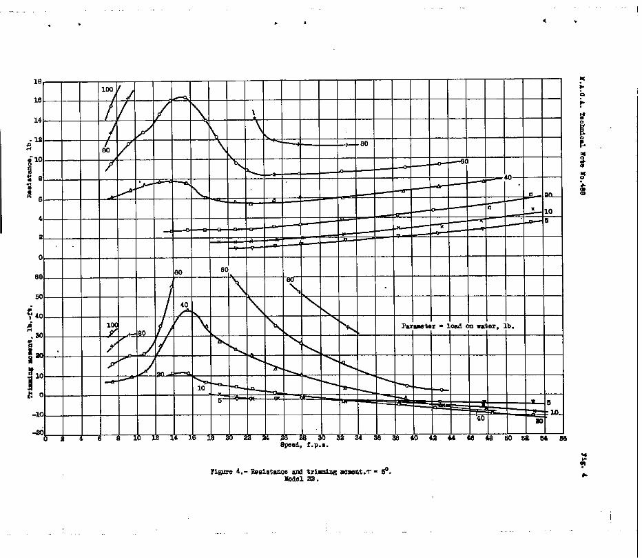
ment, and draft for each test point are given in the te.-ble of test data. All the points for one trim angle aretabulatedtogeth-er.‘The same”datqy mith,the exceptionofthe draffis,are presentedgraphicallyin figures2 to 7as curvgs of resistanceand trimmingmoment plottedagainst speed,with the load as a parameters Each figurogives th.qresults for one trim angle. The resistancegiven includesthe air drag of the model, as was explainedin rcforonco1. When the results are applied.to a iako-=off calculationthd yartzsitedrag of the hull shouldnotbo included.in tho air drag of the seaplane. 1
,“,.Tho trimmingmomonts and drafts.atrest are gi+en in
figures 8.and 9.,:”These curves maybe used to determinethe water line at rest for any displacementand center-of-graVityposition.:The trimming-momentcurves &lso givethe longitudinalstabilityof the hull at rest...,.
Nondimensionalresults.-The difficultiescaused bythe lqrge =;;-~iies in the test da%a, a~~ amethod of avoiding them, are discussed in reference1*!I!heprocedure’consistsof plotting the model resistancefor a given speed.and load against trim anglez,to deter-mine.the,.minimumresistanceand the best trim angle forthtit’pa&ti”cula&”speed and load.- Cross-plotsof miniiiiii~resistanceand best trim angle agaiust load are then pre-pared for each speed. The resultsare reduced to nondi-mensional,form and presentedas curves of resistancecoeY-f“$bion%an’d,”tg~~t”trim ang~~”against speed”coe”f’licien%,w“ith’load‘coefficientas,a paratieteroThe trimmingmo-~mc+ts are simila~~y~lottod against trim angl~ for a-gi~enlo”adand speed,-and “themoment’correspondingto the ~e-s%--trim’angle.’~ead’”-f’ro~the”c~rvec These motientsare thanreduced to nondihonsionalform and plotted again~t ~oadwith speed as,a parameter. The moment coefficientscorr-syo”ndingto eveh load”coefficientsare read fro”fithesecurv%k’and the iesults’pr”es.enkedas curves-of trimm~ng-.—.
moment coefficientsplotted against speed caaf~icient.withload coefficientas a parameter.
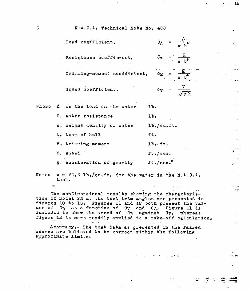
The nondimensionalcoefficientsare used only in thepresentationof data for the best trim ailgles,They aredefined as follows:
—
::. ... . ..x. , &.-
6 N.A.C.A.TechnicalNote No. 488 t
Load coefficient,A
CA = ‘~ ‘w% h
Resistancecoefficient, c= =“ ~‘wbs.~..-. ...=
Trimaing-momentcoefficient, CM = —w.b4
Speed coefficient,
whoro A is the load on t-hewater lb.
R, water resistance l-b..: .:
w, weight density of water 11)./cu.ft.—
b, beam of hull ft.
M, trimmingmoment lba-fto
V, speed ft~/sec.
g, acceleratia~of gravity ft./Oec,a—
Note: w = 6396 lb,/cu.ft.for the water in the N.A.C.A.tank.
.- . . .
The nondimensionalresults showing’the characteris-tics c,fmodel 22 at the best trim angles are presentedinfigures10 to 13. Figures”11 and 12 %oth present the val-ues of OR as a functionof CV and CA. Figure 11 isincluded.to show the trend of CR aga5nst Cv, whereasfi~ure 12 is more readilyapplied to a take-offcalculation.
. .. .. . .. .—A.ccura~.-The test data as presented”inthe “faired..——
curves are %elievedto be correctwithin the followingapproximatelimits:
.-.,,..
-..
& - -“. .
..
I

N.A.C.A~ TechnicalNote No. 488
Load +0.3 l-t).
Resistance + .1 lb.
Speed + .1 ft./see.
Trim angle + .1°
Trimmingmoment +1 lb.-ft.
DISCUSSION
Resistancecharactegisticsx-The results show that...——--the low resistanceat high speeds and light loads expected
— --.._.
of this model has been realized. Figure 11 shows reason-ably flat cU??VeS of CR against Cv ia the high-speedrange● The rise of CR noted with increasing Cv is
caused in part by the air drag of the model, which is in-cluded in the resistance. The actual water resistanceisprobably nearly constantagainst speed.in this region.
An idea of the relativemerit of this model can be ObUtained from figure 14, in which the valuo of the load-re-sistanceratio at various speed coefficientsis plotted.against load coeffici,ontfor models 22 and 11-A. Modol11-A, the characteristicsof which are given in refe~ence3, has the best performanceof any model so far tested.bythe completemethod in the N.A.C,A. tank. It is‘believedto he a ~air representativeof well-designedhulls of theconventionalAmerican type, Yigure 14 shows thatTgo~$l_22is definitelyinferiorto model 11-A at the hump speed.
—
At all the higher speeds chosen,however, the superiorityof model 22 is considerable,amountingto a ‘73-per&&iZin-crease in A/R over.that of model 11-A for a speed coe~fi-cient of 6.0 and load coefficientof 0.1.
The relativelyhigh hump resistanceof model 22 doesnot apyear to be inherentin tiledeep pointed step, hutseems rather to be causedby the upward curvatureof thebuttockstoward the bow. A longer flat on the fore%odyforward of the step, togetherwith a lower bow, wil~ p~o%-ably reduce the hump resistanceto about the same value asthat of good conventionaltypes.

~Jonentcharaat!6ristics.- In previous no,$e$on hulls——.tested by the completemethod in the N.A.C,A, tank, themomenl;coefficients“.at*be:stangles.havbnot been present-ed- !Zhereason for this omission,explainedin reference1, was the diffitiltypresentedby the iapid change oftrimmingmoment with angle. The attpmpt to establishthesecurve~$for model 22 was somewhatmore successfulthan theprevious efforts,and the curvesare presented i.nfigure13. !~hesfgn.df the trimmingmoments followsthe usual .aerodynamicconvention,i.e.,moments that tend to raisethe bow-are consideredpositive. The use of this figureto determinethe trimming.fionentsnecessary,to maintainbest I;rimangles throughouta take-offrun consistsofreading the value of CM correspondingto the values of(IV and” CA for a given“condition.”The trimmtngmomentis thdfi, :.
—... .. M’‘CMw’b4
. .where”-b is the full-scalebeam,in feel.
#~. .... .
.::.. ffprayformation”~-~he sp~ay characteristicsof,,rno$~l—....—22 tierb~~u~iedBY direct bbs&rvation-&iid-iyrneafi~of pho-togra~)hstaken during the test,s.At low speeds the hullis rather “dirty.” The bow bli”steris heavy a~d rises toa considerableheight. The upward curvatureof the ~uty=tocks near the bow is appar’eh~tly”responsiblefmr thi..e~n-de”sirableblisteras-wellas for the relativelyhigh liixapresisl;an~e,atheavy ,loati..,The.height of the blister””’.”could probably be.tiateriallyreducedby means of spraystrips, . .....
7. . . _ —-~ . :. ;~. ==*=: &.~:: =.7
A ~ronouncedroa&,-Or fe-ath”er,‘~”sraise~b~hind tfiemodel at a“speed of abo’ut10 feet per second. The pOSi-tion ~Lndhbight o“fthis roach vary with speed,and it dis-appearS+cqm@e.!eJ.yat speeds above about 12 feet pe”rsec-ond. -Theaddition o“f”a tail extensionof the usual f“oT#would probably serve to hold the roach down so-that itwould not damage.t,h.etail surfaces,without causingan ap-preciable change“i~.resistance.
A%”h$gh spe,eds”an-dl“OWangl-estfiemodel is ve’%Y’-Cl-6an.It rugs on the .fofebodyonly, and the spray cleare the af-terbot~yentirely.‘~JT~isfact accounts’for the low .iesist-ance in the ht~h-speedregion. — .- .-—
.
.
i-
.=
.—
t
.
,-

.
.
.
1$.A.C,A,”TechnicalNote No. 488 9.- —,
,-. ,.-j.’. &&e. off examQ~.Q.nThe effect of the characteristics—-———..-.--—.of’isodel.22.on take-offperformancecan best be shown %y..*,,qTk~ri.gout an example;-For this purpose the sa~e &esignsp.q:cji$i.,cationg that were used for the exampl”esin refer-.eq.~pgI,;and3 are”.assumed..They are: - “
Gross load.,, .,
.. ., ‘~ingarea.i,. ,,--77”Pqier...-:.
.. . .= =.= -= .-. .. . . .. ... ’-;’- -“. .”-’ ‘- .:...., :., : .+ Effectiveaspect ratio,.. .. . .L consideringground,.., .,,. . . ~effect........ .......
-,,sP.arasite,.dragcoefficient,.f. excludinghull
,,.--- . ...Airfoil ~
1
15,000 lb. ““—— .- .-.=
1,000:Sq.ft;-=
. .. . 7.0..”.
. ..-
0;“05
from N*A.C.A. T.R.
The relativelyhigh resistanceof model 22 at the ..hump and the low resistanceat high speeds lead to the se-lection of a low value of the load coefficient. A valueof 0.3 at the hump correspondingto a A/R of 5.08_was .chosen for the first trial. Thts selectionis based upo~inspectionof the curves of figure14. A second trial maybe requiredafter the curves of total resistanceand thrustavailablehave been constructedif the excess thrust at ei-ther~of the criticalregions is too low. The load at the “hump is assumed to be 0.9 x Ao, or 13,500pounds. The ‘
bean is thus(13500 ‘f’=———0.3X64)
or 8.9 feet.
The wing settingis determinedby the method outli~gdin reference1. The settinggiving the.leas+ tot~l re-sistanceat 85 percent of t“aestalling.sresponding-,toan angle of attack of 10’.5
~eed is 6.3°, cor-and a best trim
angle of 4,2°, .. -.
The curve of the total air-plus-water-resi&tan~6,based on these”conditions,
...—js””givenin figure 15~a], to-_
gether with the”curve for model 11-A.taken$Y?rnref~~~n~~3. The thrust curve in this figure $s t~e sgme as thatused in the previous examplesof references.1 and 30 TX;.- — .-. — —-: -- .

. . ..—
.: ----.=
.. . ,.. f ., .:- ,>
10 N,A.C.A, TechnicalNote No. 488. . . .... . ..,-.:.....’,!.: i.-: ___ ..,“. . ...
.. . ..A: .“i ,: ... . .., ... .. . . . . -i+> . . .
curvefi:”of.~ya- ,“&n&”T/al..
““b%kji.tedfr”brn’t”he”excess thrustava”i-lablefor”acceler~tio~‘b~o.wn’”byfigur~ 15(a)~ are plot-te”d”in fiCure‘15(b). “-The”.“ireaun,derthe curvb of ljarepresentstake-offtl”lde:,“~hdthai un~br the curve of V/atake-c)ffrun. Comparisonof the T/a curvesof the twomodolw “showsclearlythe superiorityof model 22 in reduc-iag tlkelength of run at high speeds.
,. ,”. ., .:,.
It may,appear from the curvee of figure l~(a) that abetter”choi.cc”:’of“Deamcould have %een made fo% either orboth nlodels.Model 22 shows.considera%lylower qxcossthrust at the hump than at high speed,while tho conversois true of.rnpdol11-A. Several trial calculationsusingdifferentbeams wore made, howover,and th-osechosonap-pear to give about the best performanceposs,~blein eachcase. A fprthor increase’i; the’bea~ of the model 22 hullwould cause’’theweight and air drag of tihehull to be ex-cessi~pelyh,igh. Some of the advantageof the low waterresistanceat hi-ghspeedswould also be sacrificed. If‘bIm,,bearnof the model 11-A hull were reduced the hump re-sistance,and thereforethe take-offtime, would be in-creasedwithout a proportionatedecrease in high-speedre-sistal~ce.The forms ofthe curves are inh.er-en”tin the-characteristicsof the two mwdels, rather than in the se”-lect”iclnof beams :forthisexamp’18. ,.
..,, .. .,+,:.....-.-.; ---J.”camparisoa~etwqen thier.diultaof:the two hull’sap+
plied t:otihadesign .condit~oti.s““assumedis.giv-enin”the.’‘~followingtable::... ‘ ‘“. ---- ......,.. :::.?:.....-:..
.-. ...... . ... . “--J:--,:“ ...-:...-..L... .,.,,... ., ;.... . ... . -.:.,.. ..liodel2.2.’:..Model 11-A... .,... . ,., . ,.”: -.
Beam 106:8 iii. 96s3 in... ,.● . . . ‘.:
Angle of wing setting 6.3° “ “ 6.?0,. .. .., -:...,..., -.{. . .. . . . . ..“LTTakp-o.ff“time“ “’ ““-2$6”.8sec.’”“ 3~’.4.8e.c.,. .. ..,.
:,.‘,T&k6-”off.”itin~“”“.;“” ;.”;”~y-$.90;-:?t~:-:;,”2.,.&j “l-t’.““”.,,- .. ..... . .... .... . “.-....-.;.., , .....-
The get-away speeds for the two hulls i’n~he exa~ploare ,no-t,exactly.:thq-same,a:s..may.-besecmfron.,figurg15(a).This,d,iscropanc.y=riscs,f.rom:t,he.fact~that+t~ptrim-anglecurva,.f~rth.crup $ust.prece@igg.,take~,o,ff.i,qaqp~ed to,boan .axt:rapolqt..~,oq:~o.f,t:ae,.tiur+e.wpto:tlie.,,$q.s~,p,o.intactua-l-lyecal.culti,ed;. ,2,+?,.$r<ia:”agf;l~.s- q~....~.ell@s.:,tEe,Fing ~e%ting for model 22 were slightly“lower“thanthose for model
.
1
r
-.
..
.-
●
.

.—
II-A,.h~n~eitheg?t:awa~ sp~ed f? high~r,...Zn~an actualtkkb~pf~,the getTawayfar eitherhull.cov~d.%emade.a~ ~.qp.13+dlow~rjj~iian:tba-j.,s~o,yn,lut’sti~la%ove ~he stalling5p~.ed~:,~y:rneau8o~.a? ?~rupt ~ull-Qf$. This phase”o~ the:problemlpnp.k~s eff.ecftontime and,run is discussedin de-ta.i.l’’i~:r~ferqnqe=,~. .;.,, . ... . ....,_LJ, ._.. -..:;.#T---
.. ‘jlh,e.~tes~”~rirn:+n~les’:forthe pxarnple,tisipg.themodel22’’hul~,.an~~the’rnome~~p.required:to hold those-angles.,.ar.~j~l~t?~d-.ag~~q;tspeed in figure.16. The trim angles“ir~~~,t~inb~,.a~a-~ar.t,.ofthe fake-off calcula~~onsand,,?$o,,rnompv$”s,are~r~,~d,$r~rnthe &urves-of.f~gur~j%~.3n%hc~mar.q&r“d~scr~b~dln,.t~e~diqcussion~f i%at figure; Thec“chtcr’’~%=uj.,~h’i.ch”the~hompents~are,.~+ken--~S ‘shownin fig-ure 1. The thrust and aerodynamicmoments should next bead~ed to the water moments, to ascertainwhether tho coa-trol is adequate: ,lJnless.thespext~rnalrnoments:are- ..strongly,~.agptiv8,,,it..q~pears:that”the center.o?gravity’of a flyi?g boa! usingthe l~nes of g-o~el22,,.lshouldbefarther forward tian the center of moments shown in figure1, sinco the water moments alone are decidedlypositive(stalling)throughoutmost of the speed range.~
,...,... .. ..,,.,
CONCLUDINGREMARKS ‘
. . .. . .., . .. ~, ,. . .
,!’he P.rei-t t~gts show the p?”Ssi~ili:y~Qf..irnproving‘ t~e water performanceof flying-boathulls by departure”.fr?m t~e,,c~nyqn$ional,de~igns.,.:Fuyjhe~.y.qr~on hulls o:”the,$yp~.of,+o@91.,22is,und~r w3Y~.. Thq.ne.xt:sfiep:inthedevelopmentis a study of,tile, effeqt~ofa f~rebqdyhavinga longer flat and a lower bow, in aa attempt to reduce.thp,hump,.rpsistancqfgr a.givenyalypof. CAI sotpat asmalle?:.hull,m-ay,.~e.USPG*.~... .:,-----’. .“. . .
,, .Wind-tunneltests’are”rb”qu~red.to determin~~hether
the qi~ dr”agQf -tupe.pointed-qt.ep,typeis reasonably~OWr.~g;~his.:o~nectjion.gq &@neralJstudy.of-the e~fectof bot-tom shapes on a#.r,drag,mopldbe of;v?lue.,.’,, ,.-~
Experimentswith designs of the same ggneral type asmodel 22, but with greater ratios of length to beam, maylead to the developmentof forms suitablefor use in twin-hull flying-boatand float-scapla~edesigns. Various an-gles of ~ead rise shouldalso bo tested i~ order to detor-mine”how groat tho detidrise may be rmde oathis tjpe ofhull without seriov.slyincreasingthe resistance,

...-.., :’”3P’.. .—:—,
12 N.A,C~A, TechnicalNote No. 488-.. . .. .....’ ...
Full-scaleexpor~mentswith a small and inoxponslveflyixg,boatwould%e of groat value in determiningthelauding characteristics,of thepoiatgd-stq hull, as wellas;it~!.tendeilcytoporpoise. These qualitiescannot beinvestigatedsatisfactorilyin thetowing tank; although-genar&ll,coastderationslead to.the expectationthat thepointed-steptype will be at least as.satisfactoryinthese respeotsas hulls of conventionalform. Some ten-dency tdward.&-~re6t20nal””instabi31ty-ias ;ote&_atlowspeedt!and.heavy’.Ioadsfor:thehull tested: T!histendencypersisted:overa very sinallrafigoof,,.spe.odsand.wouldprobably hot.:causeany difficulty;Bowevor,.full-scalo.ox-perimcbts’are.also,necessary for,determ~ningwhether thehull is extireiysatisfactoryin thts r&sp.e.ct*t-. ... * ..... .. .;.,.:,.$m..- .. .Pr,--.””””’,. .. - -.....},...,.. ....,.”’ ‘., -.,,,.. ,;Langley.h!emOrialAeronautica~-Laborat.QrX., .::,., ;..
NatiQtial.A.dvisory.Oommltteefop Aeroaauticbi : .!,:Langley.Field$ Va.,Decembe& 18g’3.933~.-; “:.:,
r. ,....,.- -,, ..... .... .. .. .“. 20.....,-, ,“.! .....-.,.,.-“..” .?..-..“, , ,...,- ,.,.:I .. ..-.. 4;. . .$:..$~..:,“..,i‘. .......
,. ,’” I&tiicEs- ., ,;;..-.-.:... :.-. .. “.....
1. Shclemaker,James ii”.,.atid,’PaYlt3QsonrJohn B.: A CompleteTank Test of a Model of a Flying-BoatHull -N.A.C.A,Model No. 11. T*N. HOC 464, N.AoC.A., 1933,
.,!-.,-r-r.~..;-~-,.... . .- .,’..,,-,e.,..+:...,_.:.-..,-................&XISCOtt,’ “’Stari:-
.-2. The.’N.A.C..?-.“Tan~- A H~gh-~pe~dTQw-
::in8 Sas+ti,forTesting.Modslsbf”~e~plan.e”%loa%ti,-“:.$,B4:No*:470.,.N.A,ciAm};.J.933”.: -.:, : ..’“: :. :,
-,... :q:....T.. ,“..,..1-?..“””. :..- : ........-... ..- .:...-...:...3. Paz’kinsob,.J.ohn.3●:. A,CQmpleteTaik Test of a~tiodelof
a fllying=30”atQUll -.N.,,A.c.A-.Moael.~o;-jl-A..,T.N. No. 47o, N.A.O.A*,1933.s , ... ,.
. -.4.,Shcleuaker,+,James M.,,eb.d:Dawson,John &t. The Z3’ffect.“. of Trim Angle on theTake-Of,fPerformanceofa Flying
,.,” 1Boat. T,N* ~Om 486, N;.A;C,.A,, 193”4:; ..,, ,,... ._ .. .,.“’..;-%-“ .-...r::.,..:-.,.. :.-..,

●
.
IT.A.CI.A.TedhnlaeilNoteNo.488 13
TA81LC
TestDataforN.A.O.A.XodelXo.32~ying-hatEull2Anematio7i000nity=0.000011ft.ajseo.
Water~eae~ty,63.6lb.~ou.~b.Watertenpera%u~e,69°F.NotezPoBit~vemomentatendtoraisethebow
Trimangle,T= a“ Tr~mangle,7a30
Lebd~p: Rael:&ce Tr&a# D~ft LoadSpeedRealetanceTrlmmlngD~f~. ... lb.f.p.a. lb. nomentlb.-ft.step lb.-f+.
in.ste~in.
5 -a6.3 1.8 0.7 20 -13.6 22-27.8 1.9 -: -15.2 u n*32.4 2.0 :: -17’.0 i% 1.738.5Y* :: .6 -19.0 :::
H!17 1,7
43.85 -a -ao.5 z.a la 1.6449.0 3.0 :: ‘22.8 3.4 1: 1.15+56.0 3.3 z .4 -a3.a 3.4 1.3
-f; s.e 1.110 -:3.: a.7 4 .8 -? .9
a.9 .8 -36:1 ;:; .1 .7-3a:8 3.2 ; .8-38.4 ~. 3.1
-41.7 4.3 .8-46.8 4.8 ; .0
-4S.8 -? :! -sa.o 6.3 .7-49.0 n -a.-65.0 4.3 -3 :: 40 :.: s.a ;. :.;
.20 -38.5
.5.0 .9 ::;
-42.5 i .7 ;$~ 11.4 >:: u-49.0 ::: .8 lo.a a.7“53.5 6.d -; .6 20:3 8.4 n
aa.s 7.2 “48 H40 6.8 -a3.a 7.0 38 1.8
::: 8.3 E H -26.0 6.9 1.6-31.0 7.0 i%? -
60 lo.a 4a -30.8 7.0 1*ZJ::: 12.4 44 2:7 -36.2 ;; ;.;
-42.0 n80 7.8 x3.a 5.6 -45.5 8.1 7 :9
9.4 16.a E 5.560
LOO 7.820 4.8
16.6 60+ 6.5 % 17% 87 4.812.s 4.6
Trimangle,7 = 3° -a%; la.6’ %+ a.a-3a.o 9.7 41 1.6
5 ,9 0 0.9+~ .7 80 5.7
i:: -?+&l
.7 ::: 1::: z 5.71.6 -1 .6 -3a.3 14.8” 66+ a.1
-a .6:gj M -2 100 6,3 10.7 33S 6.4
a.1 -a ::-5a:o a.5 -a .s Trimengle,T = 6°
10 -19.0 1.7 5 5 ao.0 .9 -a 0.7-ao.6 1.7 ::: aa.7 .9 -a .7-aa.s 1.8 : 1.1 a5.a -a-a3.o 1.8 1 .9 28.0 M ::-26.0 a.1 32,8 1.7-31.a
:: .4-: :: 38.6 a.1 -4 .5
-38.0 ::: -2 .6 42.9 a.4 4-41.8 a.7 -2 .8 47,7 2.7 4 j‘46.5 3.2 -a .s 52.8 3.4 4-5a.a 3.a 4 .6

N.A.O.A.%ohlliod. ~Ote ~0. d68 14.
.
.
TABLW(Oontinue&)
TestDataforli.A.O.A.ModelNo.22Flying-”MatEull
KLnemat10visooelty= 0.000011ft.a/eeo.Waterdensity,63.6lb./ou.ft. Watertemperature,69°F.
Note:Potaitlvemomentstendtoraisethebow
TrimUI@e, T = 6° Trimangle,T = 6°
msAspeedRe81etanoeTrimmingDraft LoadSpeedResi;&nceTrimmingD;~tlb.f.p.a. Ill. moment a% lb.f.p.e. ● moment
lb.-f*. stiep lb.-ft. fllpin. .
10 19.0 1.5 1.2 ao la.7 as 0.0-: 1.1 ::: 16.’3
%: ::: -2 .9 aa.o 14.3 %+ Ua5.4 1.7 -2 a5.a 11.9 60+a6.a 1.9 -a :: a7.6 11.5 52 :::3a.7 a.3 4 .1 33.0 3.I.4 34 1.738.6 2.94’3.3 3.0 2 :: 1~ 7.3 15.5 3a 6.7:::: -6 .5
::; -9 .4 Td.mengle,7 = 7°
ao 13.9 a.7 11 a.1 s ;;.; 1.4 -3 1.015.6 a.8 u 1.8 1.6 .717.5 6 1.6 a4:6 1.6 2 .719.0 ::: 1.6 a7.o a.2 -5 .630.8 : 1.4 32.3 a.s -5aa.6 ::: 1.2 38.0 3.3 ::as.1 : l.a 4a.a ;.: -$28.0 ::: -1 1.1 45.5 -la ::3a.5 -4 60.5 a:l -14 0
4:a -5 :; lo%: .6 18.2 1.9 -1 1.346.5 M -i; ;;.: a.o 1::5a.8 6.a -11 :; a.4 z
24;8 a.6 -5 .740 7.3 :.: 7 :.; a7.o a.e -6 .7
32a 3.6l%: 7:4 1: : 37.4 4.4 -z ::la.6 7.7 a5 :.: 43.0 -la .613.6 8.1 47.6 H -16 .315.5 ;:; :; a.0 50.6 6.2 -14 .517.6 6.119.0 :; $: 80 13.0 3.0 0 1.s20.8 ::; 23 . 14.9 3.2 a 1.8aa.5 g.: 16.3 3 :.;a5.1 . E N 18.S ::!66.0 10 1,3 19.4 ! 1:732.6 ::; 1.1 al.s ::: -1 1.339a 6.6 -: 1,0 24.7 4.0 4 1.043.0 l,o a7.a 4.547.8 H 2 .8 32.3 SJ ::
37.9 :::60 7.3 16 42.6 6.8 -16 ::
1::: 80 2:: 47.8 7.5 -10 .61::: la.8 21 60.7 8.2 -19 .6la.6 14.6 36 :;:13.8 16.0 4.a 40 6.5 5.8 -9 :.:15.4 16.4 E+ 4.1 6.3 -4 .17.6 “ X4.O 60+ ::~ -116.8 la.3 60+ ;:: 1::: :::21.0 9.6 67 12.9 ; 1: 3.1aa.1 8.9 50 ::: 14.8 :.: a3 a.aa5.a 8.4 35 1.9 16.0 6.s a.6a7.9 8.5 18.a % a.43am5 6.7 1% M 19.4 ::? 18 a.339.4 9.1 4 l.a 20.0 la43.1 9.4 2 1.2 ::: 10 ;::
E:: 8.3 5 1.526.9 8,93a.1 -: ?::37.7 ::: -la43.0 10.1 -19 :/:46,8 10.1 -21
.-
. .

.
.
N.A.O.A.TeohnioalNoteNo.488
TA3L3(Oontinued)TestDataforN.A.O.A.ModelNo.22Flying-BoatHull
Klnematioviecoslty= 0.000011ft.a~eeo.Waterdensity,63.6lb./cu.ft. Watertemperature,69°F.
Note%Positivemomentetendto relsethebow
Trimangle, T=7° Trimangle,T E 9°
L:bdyp: Reei;&noeT;:~ny D~ft Lebti;p;: Red.;;~OeT~u$~ D;~t. . . . . . . . .
lb.-ft. etep lb.-ft.in.
stepin.
60 6.6 -5 60 -158.3 1::: ::; $: 1?:; -12 :::
12.0 : 10.3 la.6 -4l?:: la.6 17 ::: 11.8 la.o :::la.9 12.6 30 4.1 13.6 11.4 12 3.814.6 la.5 46 3.9 14.8 lloa 85 3.615.9 11.5 16.8 10.6~7.a 10.2 z ::: 18.4 10.9 z ~:~18.0 :.: m 3.0 ao.o 10.916.9 aa,o 10.8 % :19.a 9:6 2: ::; a6.o ::.: 1: :.:33..7 9.1 31 25.6 1.9a4.5 9.a ::; a7.4 :$; 1.7a7.o % ;.; 31.8 . 2 1.532.3 1:::37.8 11.7 44 1:4 60 7.3 14.2 -10 6.a
16.6 460 B.4 10.0 -a 6.a $: 18.5 a :::
;:.: 11 5.9 18.9 5.6::$ 12:1 18.6 J17.7 17:6 ::+ z:: ;:.; 18.0 ::;::.: 14.6 :? 17.6 E. 12.8 ::: 16:6 16.1 60 :::
la.6 43 a.3 18.4 14.8%:: 12.43a.6 12.6 % ?:: ~:: ;;;: : ::;
a6.o 14.3 86 a:aLOO 6.4 12.’7 -2 6.9 87.0 14.3 al
sa.a 16.6 3 !:;Trimangle,T = 9°
100 17.1 -620 13.5 3.6 -16 1.8 ::: a2.a 7 :::
15.0 3.6 -lo16.9 -8 ;:: Trimengle,T = 11°18.6 ::: -6 a.630.1 4.6 -8 2.4 40 8.a -24 3.622.0 4.6 1::: -a324.6 5.3 -$ ?;: ::.: ::: -al :::27.3 -22 . 8.3 -m a.432.6 ::: 41 .1 60 13.4 -a2 4,8
40 ‘7.0 6.7 -18 4.2 1::: 12.? -16 4.46.8 7.2 -15 3.8 12.4 ~a.4 -6 3.910.4 -12 3.5 14.1 la.4 -3 3.511.8 ;:: -613.6 7.0 M 60 ;:.; -16 5.914.8 i 1::; 416.9 ;:: 11 %: la.3 18:4 :;:18.6 7.a 2.4 14.0 17.6 lE 4,420.1 7.a : 2.1 15.6 16.9 20 4.022.0 17.3 16.8 2425.0 ::: 4 ;:: 19.1 16.6 23 :::a5.5 8.3 -3.87.4 H3a.5 1::: -z l.a
.—— ..— .
-,

. ,
I
Base
a, 1.8b, 2.4
All dimen-sions ininchas
line
k+. m-—--h USJJ OF WFWiTS-lNC,+E9
I MAW- ORCAOTH
Base
linem
u
m
ma
15@re 1.- Lines and offseksof lL& CA Model 22.
t
Baselinlsms
WL4ma
WL2
ml

. , . b 9 .
16lm ,
MJ 80
/’ /14
+/
00
~lad
g-10/ /
9 4a
%8z&
/
6 — — - — - —- — -
20
4 4- -
10.x - — — + -
a — —v
—6 :- - — — - — — — — —
0 .
60
8&+ -so
<40 60 ~fl
MrmMt m = led C’nm*=, lb.#j
ii;40A ‘
d 10
;Eo
-lo
-al
Spcea,f.p.l.

. . . .
rip S.-%mirtallw a tridng rent.?- -$.MMel =.
.-
-.
. . . .“1
4 .
18. I , , 1 1 [ I I I I i I
1s. / 4 /
14,
4
I
. u. I
-2
0 I
60 6080 WJ
w )’
i / ,.P40
.\= , ,, 40.2“1 I I
go
-ai36sB404a44M148
Speed, f.p. ~.Eo6a545s
Twnw ~.- RQaiatanceam trimlng mmnt..t- g.McdOlaa.
.-

. ● ✎ ✎ 4.I
I
H.SIR*K.-&mlatm& t#mbg -t..r = P. m
I

Y.A.tl. A. TeolmioalITote Ho. 488 rig. 6.
d
aa
a4100
aa
m
1880
16 *~ ! ..14
- -+- 4- - eo
i/
~ la # *f
/- /
.40I!10k
+%/’ /
-
8 -& & +
6- - \ +0
4 e ~/ -
a
o-Paremoter= 10adonwder, lb.
.80
m /~
40
80
; aoy~ 10 100.
i~-lo8 0“
?I-20&-30
-40ad
-60
-600a4f38101a 141618 ao aa a4 aa aa 30 32 a4 M
Speed,f.p.s.
rive 13.-Renint~oeandtrimmingmoment.T - 9°.Hodel aa.
—

-.
. , .
m
u
14
--—Epml, f.p.s.
nglue 7.-R8aiwtu @&l# -*. T -110.
m
40 — M60● PCcm!J tar - disp14mmnt, lb.
so
-xl I I I I I I I I I I I I I I I———0 1 a 3 4 6 e ?
[email protected], ti@!Sel
I 1

—
I.A.O.A.?OOhlliOd IO*CIMO.g [email protected],11
la-
11 .45
10
;8m38 Parme*er- OA“ ~~8 .ao — — — — HemIlineforuse in firstapproximation.87
0-
1
8
!36
4
%48
z
a
i
0 1 a a 4 5 6 7— 8 QQv=*
F@ure 10.- Variation~gdf&a~atrimangle,-rO,withO-V..
.la
.11— — — ~53
.10 /n ,.65
.09
.Oa
q~ 07.,60
; “m .40.0s .s6-
.30.04
.26,‘ \ \
.03 .ao”“y~ _
.Oa .15
.10 ~ -.01— — — — —
——
~—.05
Io
I1 a
I I I3 4
I I5 6
I7 8 9-
_l .--l Ill, f I
-Ml— I I
—“=*Figure11.- Variationof~ withOVatbed trimamgleo.
Modelaa.

“ . . . m“ ,
d
I 1

. .
ba. -J ml
I ml I I I 14--+-HII I 11111 I I I Inllllr
8
7
6
3
a
1
0
‘A=w%
F@ure 14,-EffeotofOAonAIRat?.wttrim angles.
[ill I

4,m \\ \ /ThrIut (a)
-
s\ ~
J . -- -e- - .,?otd seaiatenOO
i a,ccJOT --
- - . —
~(1 I
9 Is
i‘JI
I
-a1,~1
P? I 11IIII
o
Mmlelaa-------- kxieln-A
.7 ‘m
.8 20. .
1 # I I I I I 1 1 1 1 1 I00 m 40 80 80 100
7, f.p.s.
Figl.uaM.- o&N&lSOnAkYtw ~aa+ff WHO-O of -lo
1