National Core (NCore) and State and Local Air Monitoring ...

National Air Monitoring Conference - 2006
Technical Support of NCore
Implementation
Gas Instrument Support
Dennis Mikel
EPA Office of Air Quality,
Planning and Standards
National Air Monitoring Conference - 2006
• Overview of NCore Requirements
• Mass Flow Controllers (MFC) Calibrators
• Compressed Gas Cylinders
• Zero Air Generators
• Summary

National Air Monitoring Conference - 2006
Overview of NCore Requirements
• Quality Control (QC), i.e., Precision Checks
• Multipoint Calibration
• Level I/Zero Span Checks
• Method Detection Limit (MDL) Test
• Zero Air Certification Test
• To perform these test you will need:
– Mass Flow Calibrators (MFCs)
– Compressed Gas Standards
– Recommends Zero Air Systems

National Air Monitoring Conference - 2006
• QC Checks (Precision):
– Required (40 CFR 58 Appendix A)
– Minimum: Once every two weeks
• Multipoints: 1 in 6 months, repair or startup
• Level I Zero Spans: Recommend Daily
• MDL Tests: Annually
• Zero Air Certification Test: Annually
NCore Calibration and QC Checks

National Air Monitoring Conference - 2006
.20 ppb
50 ppb
90 ppb
0.100 ppb
10 - 15 ppm
0 to 100 ppb
SO2
500 ppb
2500 ppb
4500 ppb
40 ppb
200 – 300 ppm
0 to 5000 ppb
CO
40 ppbPrecision Level
100 ppbMid Point Span
180 ppbLevel I Span
0.050 ppbzero
Calibration Ranges
10 – 30 ppmCylinder
Concentation
0 to 200 ppb Full Scale Range
NOy Item
NCore Calibration and QC Checks

National Air Monitoring Conference - 2006
Method Detection Limit Test
• Use a concentration of 2.5 to 5 times the instrument signal/noise
• Run zero gas through analyzer
• Dilute the calibration gas to estimated concentration level and
collect readings for a predetermined length of time:
– Suggested: 20-25 1-minute observations, repeated 7 times
over the course of 5 -14 days. Average the concentration from
these readings.
• Calculate the MDL as: ( ) stMDLn
⋅= −1,01.
Where t .01,(n-1) represents the 99th quantile of a Student’s t distribution with
(n-1) degrees of freedom and n represents the number of replicate
measurements and s is the standard deviation.

National Air Monitoring Conference - 2006
Zero Air Certification Test
• Replace the zero air generator with certified zero air
cylinder
• Program Calibrator to perform a zero test
• Compare the results of the cylinder to air generator.
If response to generator and cylinder are equal to or below: – NO 50 ppt
– SO2 100 ppt
– CO 40 ppb
Then, generator is operating within tolerance for Precursor
Gas instruments.

National Air Monitoring Conference - 2006
MFC Theory
• MFC technology works on a very simple principle!
• Each MFC has a Thermister (a Thermal Resistor)
– Thermisters are sensitive to heat
– As air passes over it, it loses heat, the more air flow,
the more heat that is lost
– This action changes the resistance of the thermister
– The change in resistance is monitored by a sensitive
electronic feedback loop. The resistance is converted
to voltage and controlled by computer.

National Air Monitoring Conference - 2006
MFC Theory-Calibrator Diagram
Zero Air MFC

National Air Monitoring Conference - 2006
MFC Calibrator Features
Thermo (TEI) Model 146 Environics Model 9100
National Air Monitoring Conference - 2006
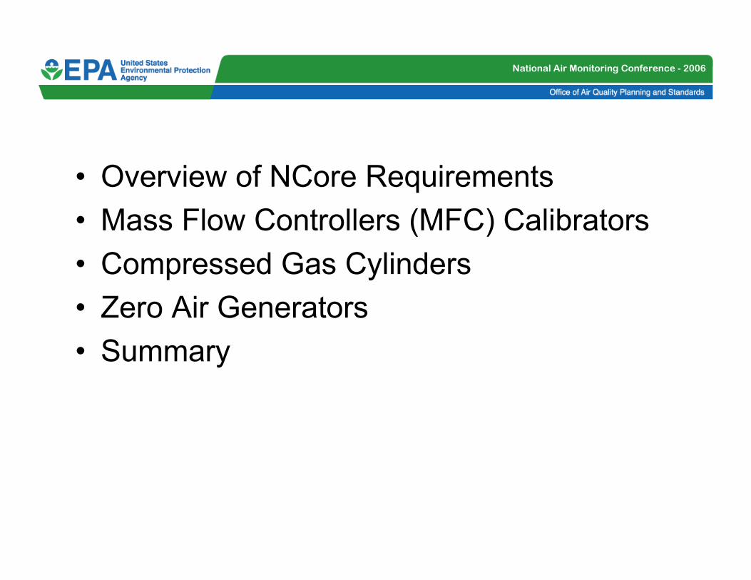
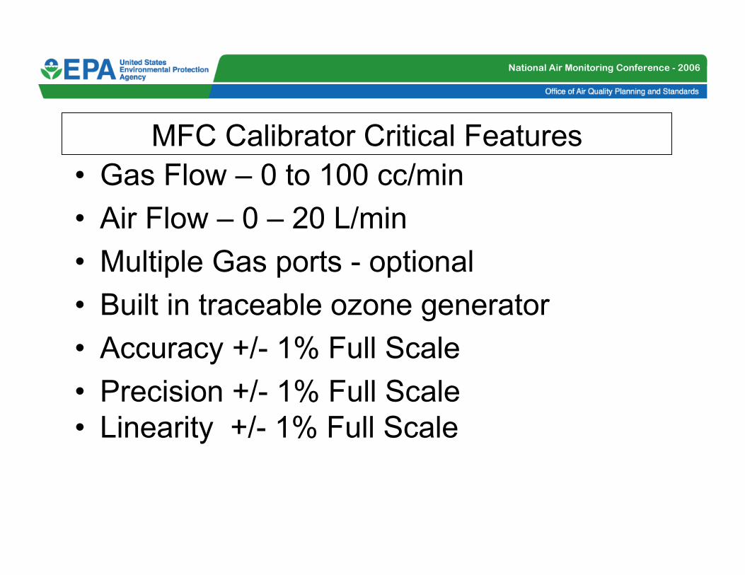
MFC Calibrator Critical Features
• Gas Flow – 0 to 100 cc/min
• Air Flow – 0 – 20 L/min
• Multiple Gas ports - optional
• Built in traceable ozone generator
• Accuracy +/- 1% Full Scale
• Precision +/- 1% Full Scale
• Linearity +/- 1% Full Scale

National Air Monitoring Conference - 2006
MFC Calibrator Matrix
1.5%
Full Scale
+/- 1.0%
Full Scale
+/- 1.0%
Full Scale
Yes NA0-20 lpm0-200
sccm
Thermo
146C
0.5%
Full Scale
+/- 0.2%
Full Scale
+/- 1.0%
Full Scale
Yes, 0.1
– 10
ppm
4 Std.0-20 lpm0-200
sccm
Teledyne-
API 700E
0.5%
Full Scale
+/- 0.1%
Full Scale
+/- 0.5%
Full Scale
Yes, 0 –
2 ppm
Yes0-10 lpm0-100
sccm
Tanabyte
300
0.5%
Full Scale
+/- 0.15%
Full Scale
+/- 1.0%
Full Scale
Yes, 0 –
2 ppm
Yes0-20 lpm0-1000
sccm
Sabio
4010L
1.0%
Full Scale
+/- 1.0%
Full Scale
+/- 1.0%
Full Scale
Yes, 0.5
– 1.25
ppm
2 Std.0-20 lpm0-100
sccm
Environics
9100
0.15%
Full Scale
+/- 0.15%
Full Scale
+/- 1.0%
Full Scale
Yes, 0 –
1ppm
4 Std.0-20 lpm0-500
sccm
Ecotech
1100
LinearityFlow
Precision
Flow
Accuracy
Ozone
Gen.
Gas
input
Ports
Air*
Flow
Gas*
Flow
Calibrator
* Highest optional ranges.
National Air Monitoring Conference - 2006
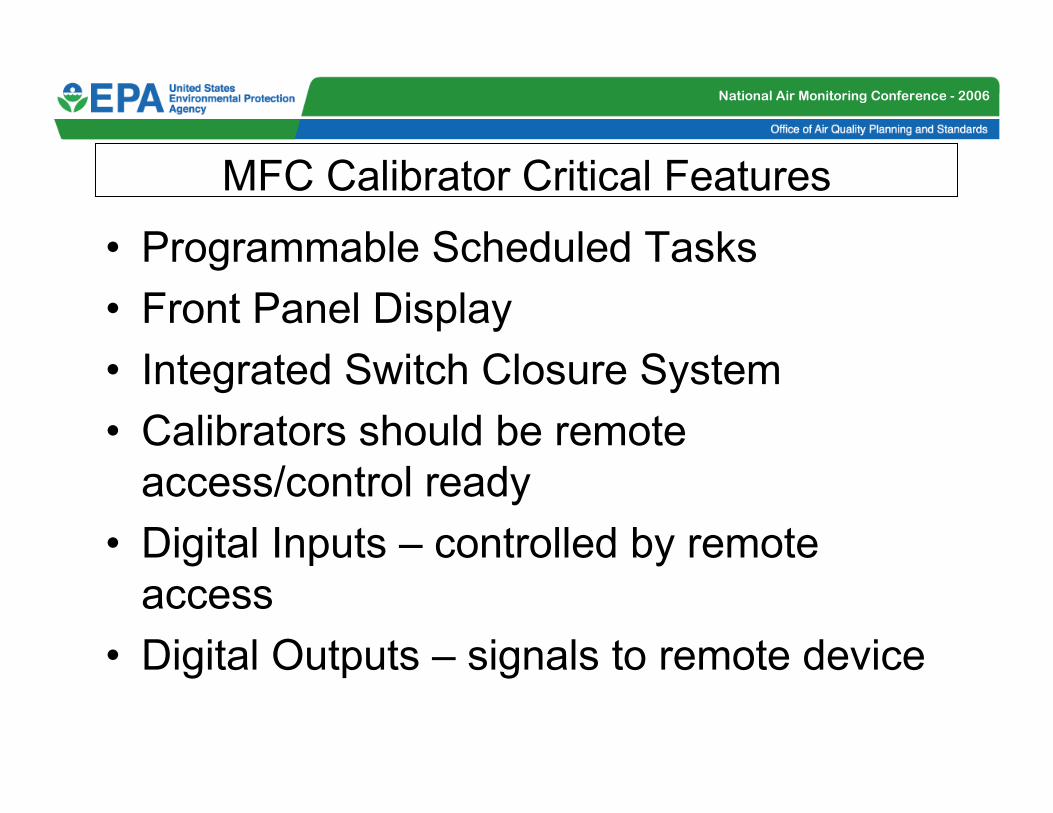
MFC Calibrator Critical Features
• Programmable Scheduled Tasks
• Front Panel Display
• Integrated Switch Closure System
• Calibrators should be remote
access/control ready
• Digital Inputs – controlled by remote
access
• Digital Outputs – signals to remote device

National Air Monitoring Conference - 2006
MFC Calibrator Matrix (cont.)
RS-232 remote
access
RS-232 remote access4 line LCD10 calibration eventsThermo
146C
Via RS-232
12 opto-isolated
outputs
Via RS-232
12 opto-isolated inputs
2 line LCDReadout and control by
front panel
Teledyne- API
700E
Transparent pass
serial I/0 after
programmable
pass-code is
received
TTL contact closures
allows remote
operation
Via RS-232 300 -9600
baud
LCDMenu operation allows
auto or manual
calibrations
Tanabyte
300
24 bit output,
2 serial ports for
communication
24 bit Digital Input, TTL
logic levels, RS-232
Bright active
matrix color
display
20 timer driven cal
routines, user defined
sequences on a 7 day
calendar
Sabio
4010L
8 digital outputs
for sequence
indication
Optional RS-232 serial
data interface
LCD Yes, 21 sequences
(3/day) through 5 points
Environics
9100
8 digital outputs
for sequence
indication
Relay contact closures
or TTL logic
4 line LCD Yes, 20 sequences
cycled through 5 points
Ecotech 1100
Digital OutputsDigital InputsDisplayProgrammable
Calibrations
Calibrator

National Air Monitoring Conference - 2006
MFC Calibrator Issues
– Certify your MFC against a NIST traceable flow device (such as a Bios DryCal, Gilibrator or Hastings Bubble Kit or other flow device)
– NIST Traceable flow device should be certified annually (or if you suspect a problem)
– Perform quarterly checks of your MFCs (or until establish trend)
– Calculate True flow vs Flow Set Points
– Air Flow: 0 – 20 lpm (recommended)
– Gas Flow 0 – 100 cc/min (recommended)
– Corrections should be made to STP (25o C and 760 Torr)

National Air Monitoring Conference - 2006
MFC Calibrations
19.32819.99020.000
18.15418.00018.000
16.17015.99016.000
14.08014.00014.000
12.10412.00012.000
10.16010.00010.000
8.1067.9958.000
6.1945.9956.000
5.1874.9865.000
BIOSDisplaySetting
97.40399.995100.000
89.50589.97890.000
78.67080.09080.000
67.69769.99470.000
56.12259.97660.000
46.42449.95850.000
36.54039.94140.000
26.61629.97530.000
17.07319.95720.000
10.54612.91313.000
7.6169.93310.000
BIOSDisplay Setting
Air Flow Results (lpm) Gas Flow Results (cc/min)

National Air Monitoring Conference - 2006
MFC Calibrations
Env i r oni c s MFC 1 ZA Ca l i br a t i on 12 / 16 / 0 4
LPM
y = 0.9694x + 0.424
R2 = 0.9981
02468
101214161820
0 2 4 6 8 10 12 14 16 18 20
Ta r ge t S e t
Env i r onic s MFC 2 GAS Ca l ibr a t i on 12 / 16 / 0 4
SCCM
y = 1.0138x - 3.323
R2 = 0.9992
0
20
40
60
80
100
0 10 20 30 40 50 60 70 80 90 100
Ta r ge t S e t
Air Flow Calibration
Y = 0.9694x +0.424
R2 = 0.9981
Gas Flow Calibration
Y= 1.0138x -3.323
R2 = 0.9992

National Air Monitoring Conference - 2006
Compressed Gas Cylinders - Features
• Come in variety of sizes (size 50 or 150)
• Get EPA Protocol certification
• Use Stainless Steel regulators and
cylinder valves
• Use Stainless steel or Teflon lines from
Regulator to MFC (Teflon recommended)

National Air Monitoring Conference - 2006
Compressed Gas Cylinders - Issues
• Recommend reputable vendors
• Handle with Care
• Make sure the cylinders are secure!!
• Read your MSDS Sheets
• Leaks!!

National Air Monitoring Conference - 2006
Zero Air Source - Features
TEI Model 111 T_API Model 701
National Air Monitoring Conference - 2006
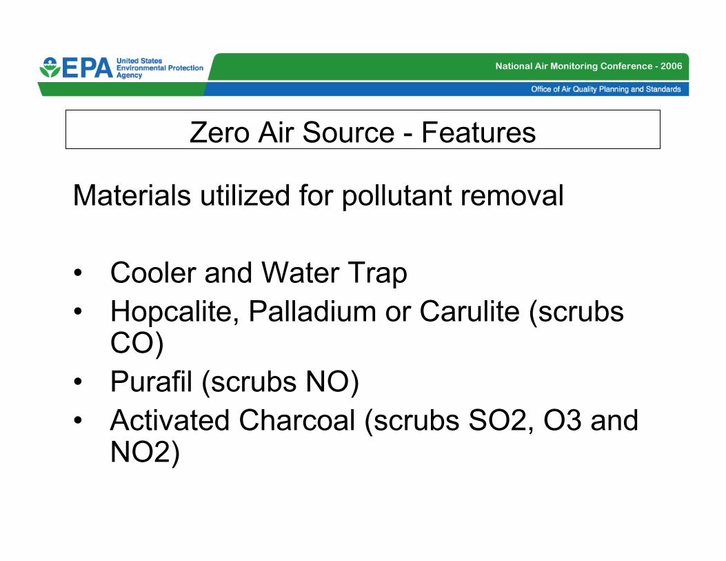
Zero Air Source - Features
Materials utilized for pollutant removal
• Cooler and Water Trap
• Hopcalite, Palladium or Carulite (scrubs CO)
• Purafil (scrubs NO)
• Activated Charcoal (scrubs SO2, O3 and NO2)
National Air Monitoring Conference - 2006
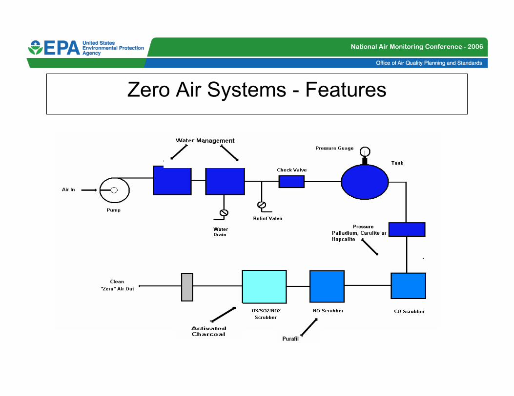
Zero Air Systems - Features

National Air Monitoring Conference - 2006
Zero Air Source - Issues
The Zero Generator or Cylinders should be
able to provide air below the stated Lower
Detection Limits of the instruments you are
testing. How clean is clean??
•NO 50 ppt
•SO2 100 ppt
•CO 40 ppb
Check the specifications before you purchase.

National Air Monitoring Conference - 2006
Summary
• QC Checks and Calibrations are required for
NCore Monitoring Stations
• The MFC systems available today are compatible
with the PG instruments
• Lower concentrations cylinders are required
since PG instruments have lower ranges and
levels of detection
• Gas cylinders should be certified – EPA Protocol
• Zero air generators should be able to “scrub”
below the LDLs of the PG instruments

National Air Monitoring Conference - 2006
Dennis K. Mikel
EPA - Office of Air Quality, Planning and
Standards
Technical Support of NCore
Implementation
Manifold and Inlet Design

National Air Monitoring Conference - 2006
Outline
• Sample Manifold Issues
• Residence Time Determination
• Types of Manifolds
• Line Placement
• Ambient/Calibration Manifold Interface
• Through the Probe (TTP) Audits
• Summary

National Air Monitoring Conference - 2006
Sample Manifold Issues
There are important variables affecting the
ambient air gaseous instruments sampling
manifold design:
•residence time of gases
•construction materials
•diameter, length
•flow rate
•pressure drop

National Air Monitoring Conference - 2006
Sample Manifold IssuesConstruction materials
Code of Federal Regulations (CFR), Title 40 Part 58, Appendix E.9a states,
“For the reactive gases, SO2, NO2 and O3 special probe material must be used for
point analyzers….Of the above materials, only Pyrex® glass, and Teflon® have
found to be acceptable for use as intake sampling lines for all the reactive
gaseous pollutants…. Therefore, borosilicate glass, FEP Teflon or their
equivalents must be the only material in the sampling train…”
• Borosilicate Glass
• Teflon• fluorinated ethylene propylene (FEP)
• Polytetrafluoroethylene (PTFE)*
• Aluminum or Steel OK if glass or Teflon lined
*Not in the CFR, however, it is an equivalent material

National Air Monitoring Conference - 2006
Residence time Determination
Code of Federal Regulations (CFR), Title 40 Part 58, Appendix E.9c states,
“Ozone in the presence of NO will show significant losses even in the most inert probe material when the residence time exceeds 20 seconds. Other studies indicate that 10-second or less residence time is easily achievable.” Therefore, sampling probes for reactive gas monitors at NCore must have a sample residence time less than 20 seconds.”
Total Volume = Cv + Mv + Lv
Where:� Cv = Volume of the sample cane and extensions
� Mv = Volume of the sample manifold and trap
� Lv = Volume of the instrument lines from the manifold to the instrument bulkhead

National Air Monitoring Conference - 2006
Residence Time Determination
Each of the components of the sampling system must be measured individually. To measure the volume of the components, use the following calculation:
V = pi * (d/2)2 * L
Where:
� V = volume of the component
� pi = 3.14
� L = length of the component
� d = inside diameter

National Air Monitoring Conference - 2006
Residence Time Determination
Hot Wire Flow Device
• Real-time flow
• Thermistor Type
• Allows operator to
track flow deviations

National Air Monitoring Conference - 2006
Residence Time Determination

National Air Monitoring Conference - 2006
Types of Manifolds
There are a number of different types of
manifolds available
• Laminar Flow
• Teflon lines
• ”T” Type – Horizontal Modular
• CARB - Octopus
• Vertical Manifold

National Air Monitoring Conference - 2006
Types of Manifolds
Laminar Flow
• High Flows
• Difficult to Clean
• Temperature
Difference
• Can’t be audited by
TTP
• Not Allowed in New
Regulation (40 CFR
58)

National Air Monitoring Conference - 2006
Types of Manifolds
Teflon Lines
• Teflon lines can deteriorate in sun and
weather (dry winds)
• Difficult to Clean
• Insect Accumulation
• Pressure differentials
National Air Monitoring Conference - 2006
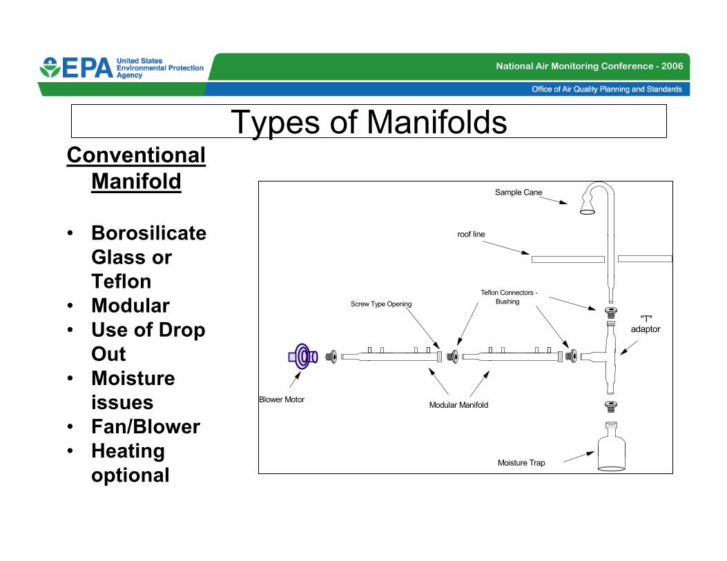
Types of ManifoldsConventional
Manifold
• Borosilicate
Glass or
Teflon
• Modular
• Use of Drop
Out
• Moisture
issues
• Fan/Blower
• Heating
optional
Sample Cane
Blower Motor
Teflon Connectors -
Bushing
Modular Manifold
Moisture Trap
roof line
Screw Type Opening
"T" adaptor
National Air Monitoring Conference - 2006
Types of Manifolds

National Air Monitoring Conference - 2006
Types of Manifolds

National Air Monitoring Conference - 2006
Types of Manifolds

National Air Monitoring Conference - 2006
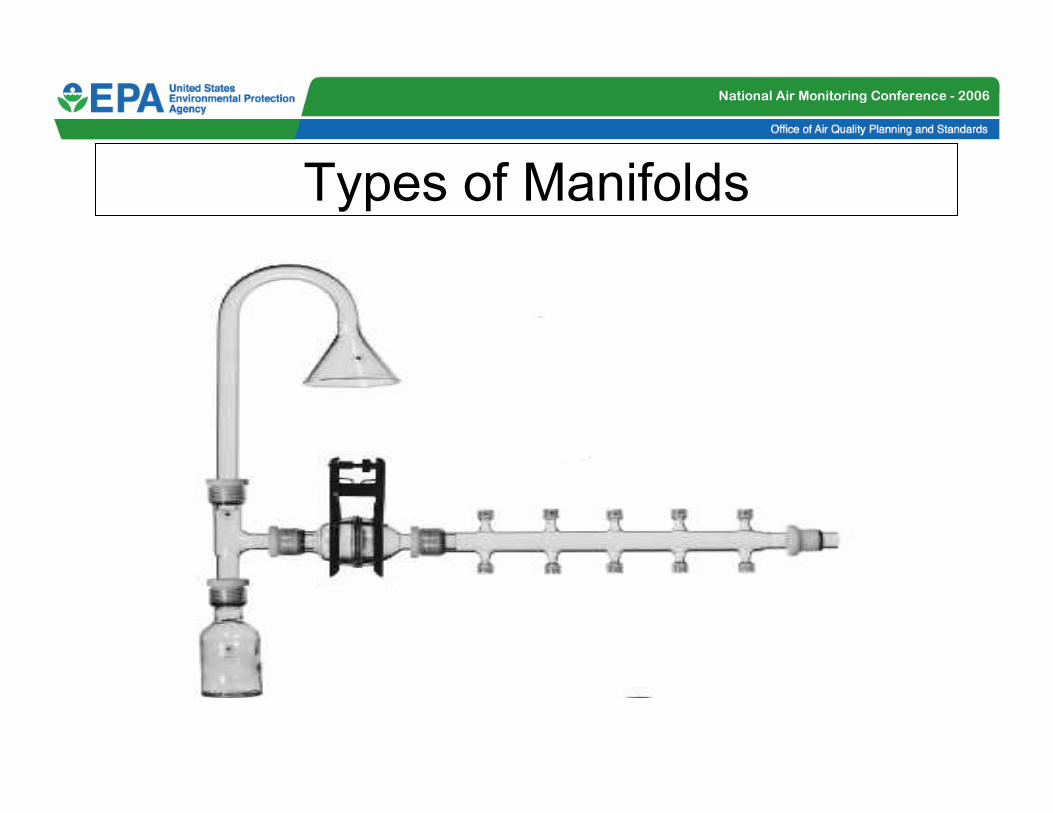
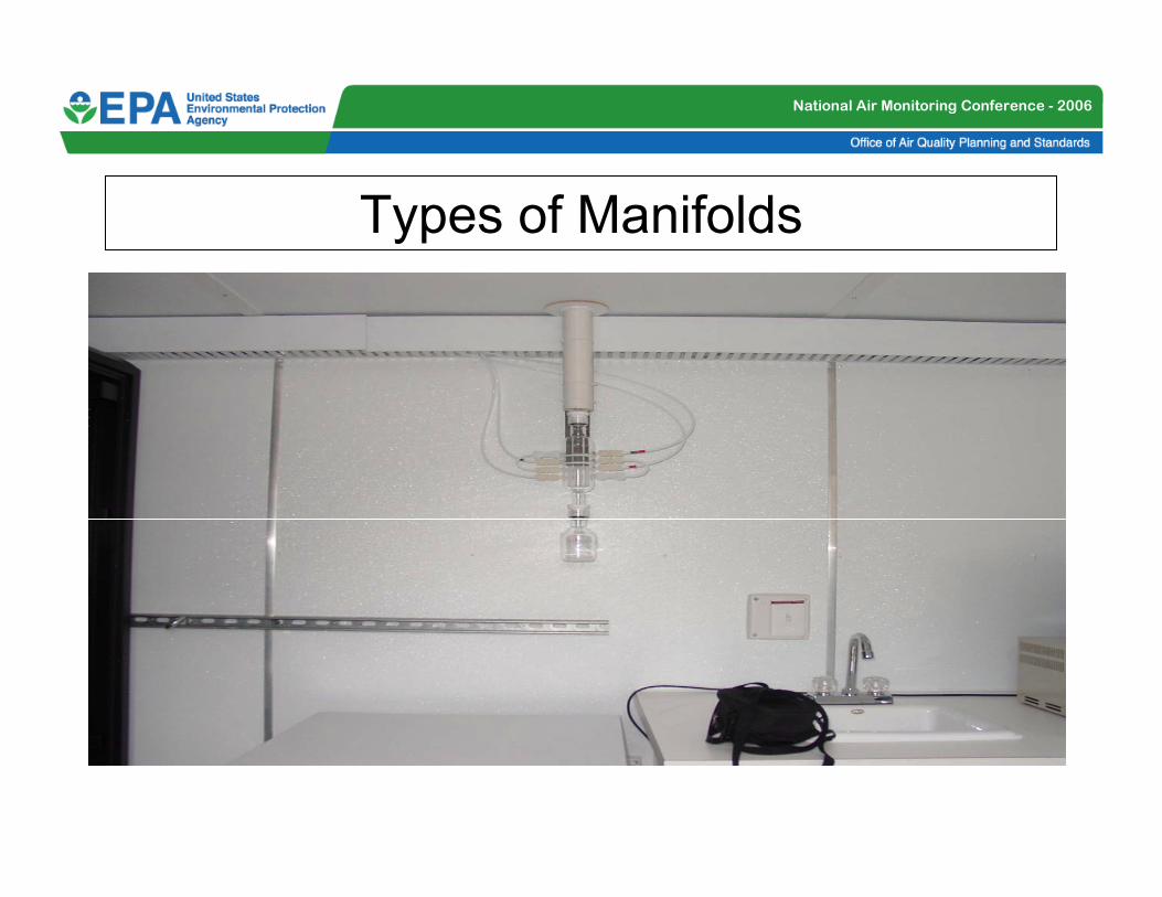
Types of Manifolds
CARB/Octopus
Style
• Borosilicate
Glass
• Low Profile
• Drop Out
• No need for
Blower
roof line
S crew Type O pening
Moisture Trap
S am ple C ane
Teflon Connectors -
Bushing
8-port "O ctopus"
M anifo ld

National Air Monitoring Conference - 2006
Types of Manifolds
National Air Monitoring Conference - 2006
Types of Manifolds

National Air Monitoring Conference - 2006
Types of Manifolds
Vertical Flow
Manifold
• Borosilicate
Glass
• Moisture issues
• Heating optional
roof line
Support Pipe
Glass Manifold
Sample Ports
Blower Motor
Insulation
Heater Power Cord
Manifold Support
Exhaust Hose
Floor
"T" Connector
National Air Monitoring Conference - 2006
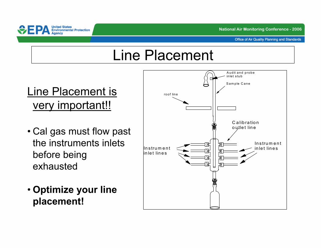
Line Placement
Line Placement is
very important!!
• Cal gas must flow past
the instruments inlets
before being
exhausted
•Optimize your line
placement!
ro o f lin e
S a m p le C a n e
A u d it a n d p ro b e in le t s tu b
In s tru m e n t in le t lin e s
C a lib ra tio n o u tle t l in e
In s tru m e n t in le t lin e s

National Air Monitoring Conference - 2006
Ambient/Calibration Manifold Interface
Burden’s
Creek
Monitoring
Setup
•Solenoid
Switching
•Calibration
Manifold
•Interface to
DAS
Burden's Creek Sampling Station - OAQPS/EMAD
Environics
9100 Cal Sys
TECO 42CY TL
NOx
TECO 43CTL
SO2
TECO 48CTL
CO
P
VVS
SSS
F
V
Other Monitor
(O3 etc)
C
CCC
NC
NC NCNC
NO
NONONO
External Moly
ConverterSampling Cane
Manifold Fan
Charcoal
Scrubber
4-ft
Notes:
S - Teflon 3-way Solenoid
P - Pump
F - Manifold Fan/Blower
V - Vent
- Particulate Filter
Sample tubing lengths < 3-ft
Cal Standard
(triblend)
Temp/
Pressure/RH
Calibration Manifold
Ambient Sampling Manifold
UPS Power
Supply
Zero Air
Source
Cal
NOy
NO
Sample In
EnviDAS Data
Acquisition System
Analog Inputs -
To Analyzers/
Sensors
Control Outputs
- To Environics
Cal Sys
Control Out- To Solenoids
Modem
Desktop System

National Air Monitoring Conference - 2006
Ambient/Calibration Manifold Interface
Burden’s
Creek
• Solenoid
Switching
• Calibration
Manifold
• Interface to
DAS

National Air Monitoring Conference - 2006
Ambient/Calibration Manifold Interface
Burden’s
Creek
Calibration
System
Air Flow to the Analyzers
NO
NC
NONO
NCNC
COM
Calibration
Gas from the Mass Flow Calibrator Exhaust
Air FlowAir Flow
Air Flow to
Exhaust Fan
Air FlowAir Flow Air Flow

National Air Monitoring Conference - 2006
Through the Probe Audit

National Air Monitoring Conference - 2006
Zero
Air
High
CO
38
ppm
Low
CO
7.85
ppm
150 ppm
SO2
-------
335 ppm
NO
---------------
15,000
ppm
CO
Zero Air Generator
GPT Calibrator
Rear Manifold (Glass)
Front Manifold (Glass)
CO Analyzer
Ozone Analyzer
Solenoid Valves
Pressure Regulator
Needle Valve
CO Analyzer
Calibration Tanks &
Pressure Regulators
Multi Blend Gas
Tank & Pressure
Regulator
Three Way
Manual Valve
To presentation line
(3/8” o.d., 150’ long
Teflon line, in ½”
i.d. steel jacket)
¼” SS Tee
Needle Valve
Bypass Flow
Rotameter
¼” SS Manifold
1/8” SS line
TTP System
Design
National Air Monitoring Conference - 2006
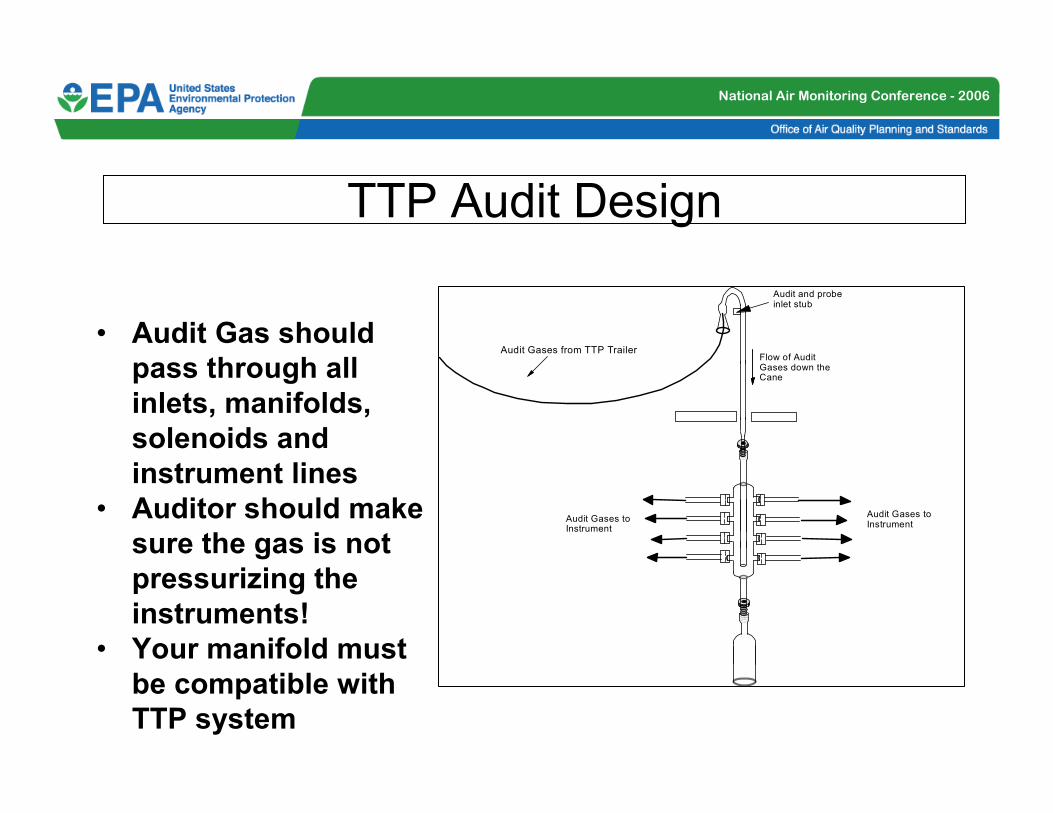
TTP Audit Design
• Audit Gas should
pass through all
inlets, manifolds,
solenoids and
instrument lines
• Auditor should make
sure the gas is not
pressurizing the
instruments!
• Your manifold must
be compatible with
TTP system
Flow of Audit Gases down the Cane
Audit and probe inlet stub
Audit Gases to Instrument
Audit Gases from TTP Trailer
Audit Gases to Instrument

National Air Monitoring Conference - 2006
Summary
• Numerous issues to be considered
• There are a number of designs
• The sample manifold must be “integrated” into
the monitoring system
• Solenoids can be the link between the
calibration/ambient systems
• DAS allow the user more freedom to control
the monitoring systems
• Your manifolds will need to be compatible with
TTP audits