Technical Supplement - Remote Satellite
31
V25 MULTIPLEXER SUPPLEMENTARY MANUAL V1.0 Technical Supplement www.vocality.com
Transcript of Technical Supplement - Remote Satellite

V 2 5 M U L T I P L E X E R S U P P L E M E N T A R Y M A N U A L V 1 . 0
Technical Supplement
www.vocality.com

BEFORE INSTALLING THE UNIT
PLEASE REFER TO THE SAFETY INSTRUCTIONS IN APPENDIX A
ContactsFor further information, contact:
Vocality International Ltd
Lydling Barn
Lydling Farm
Puttenham Lane
Shackleford
Surrey GU8 6AP
United Kingdom
Tel +44 (0) 1483 813 120
Fax +44 (0) 1483 813 121
For technical support, email [email protected]
For sales information, email [email protected]
For online support, registered users should visit www.vocality.com and select the ‘support’ section.

Table of Contents
1 Introducing the V25................................................................ 5
1.1 General Overview ..........................................................................5
Capabilities..............................................................................................71.1.1 Analogue Voice/FAX.................................................................... 71.1.2 Secure Voice Relay..................................................................... 71.1.3 Data......................................................................................... 71.1.4 10/100base-T Integrated Router .................................................. 71.1.5 USB ......................................................................................... 81.1.6 Control and Monitoring................................................................ 8
1.2 Restrictions ...................................................................................81.2.1 Slot and Port Numbers................................................................ 81.2.2 The DATA menu......................................................................... 91.2.3 The VOICE menu........................................................................ 9
2 Installation ........................................................................... 10
2.1 Supply and Voltage Connection ...................................................10
2.2 Environmental .............................................................................10
2.3 Mechanical Construction..............................................................112.3.1 Fitting an SVR Card .................................................................. 122.3.2 OEM Integration....................................................................... 13
2.3.2.1 Parallel Interface.................................................................. 132.3.2.2 Serial Interface .................................................................... 132.3.2.3 Remote LEDs....................................................................... 14
2.4 TIE-LINE mode ............................................................................15
3 Comparison with V100.......................................................... 16
4 Features................................................................................ 17
4.1 Indicators....................................................................................17
4.2 Alarms .........................................................................................17
4.3 Clocks ..........................................................................................17
4.4 Software Feature Keys.................................................................19
5 Appendix A : Safety and Approvals ....................................... 20
5.1 DECLARATIONS OF CONFORMITY ................................................22
6 Appendix B: Pin Assignments................................................ 24
6.1 Supervisor Cable..........................................................................24
6.2 Data Ports....................................................................................25
6.3 Analogue Voice Ports...................................................................25
6.4 10/100base-T Ports ....................................................................26
6.5 JP3 Parallel Host Expansion Connector........................................26
V25 Multiplexer Supplementary Manual 1.0
6.6 J8 Serial Host Expansion Connector.............................................27
7 Appendix C: Specifications.................................................... 28
8 Appendix D: Part Codes ........................................................ 30
9 Appendix E: Abbreviations .................................................... 31
Page 4 of 31

C H A P T E R 1 : I N T R O D U C T I O N
Chapter
11 Introducing the V25
1.1 General Overview
The V25 Multiplexer is the most compact and fully featured member of the Vocality multiplexer
range. It provides an impressive range of core Vocality features such as analogue voice, data
and bridge/routing in an extremely light and portable package and is completely compatible
with all V50, V100 and V200 equipment. By using the same control software as the other units
in the range, the same management interface can be used to control the unit.
The V25 is designed to support two voice/fax channels, two 10/100base-T Ethernet
connections and has two data ports. In order to minimise size and weight, the voice channels
are presented with only FXS POTS and 4-wire Tie-line interfaces. Any of these services will
interoperate with a full-size unit at the network hub, where gateway connections are made to
the rest of the network. Optional STU-III relay functionality is provided by the addition of the
V25 Multiplexer Supplementary Manual 1.0 Page 5 of 31

C H A P T E R 1 : I N T R O D U C T I O N
Vocality Secure Voice Relay Card (VI68718) in two-channel form – Compatibility with legacy
STU relays is not supported in the initial release.
Both data ports conform to the standard Vocality DB15 pinout specification and are presented
on high-density connectors for smallest size. Either may be configured to be an aggregate link
or tributary port but Port 1 is presented as DTE only and Port 2 as DCE only, although typically,
users will tend to use the black (lid) end for aggregate traffic and the metal (chassis) end for
tributary applications. They may be synchronous or asynchronous and configured to use V.24,
V.11, RS530, V.35 or RS449 electrical interfaces all selectable from the supervisor port without
the need to remove the lid. Each data port provides considerable flexibility in clocking options.
This allows a unit to accept, source or onward link clocks.
New technology incorporated within the V25 allows the maximum data throughput limit to be
raised from the V100 standard of 2.048Mbps to 5.12Mbps in the aggregate. A new, highly
stable internal oscillator and PLL design guarantees clock accuracy and stability under all
conditions and state-of-the-art SLIC technology provides a highly programmable and robust
POTS interface with exceptional clarity.
A V25 network may be managed from the dedicated supervisor port of any chassis in the
network. The user logs on to the required unit and configures the network from the most
convenient management port using a clear and simple display, which may be accessed using a
PC running a terminal emulation package such as HyperTerminal under WindowsTM.
Alternatively, the supervisor may be operated in a terse teletype mode for integration into a
central network management system. In either case, the port uses an asynchronous RS232
interface presented on a 6-way locking mini-DIN socket.
This user manual describes the use, configuration and installation of the V25 Multiplexer and
contains information relating mainly to its unique features. It is not intended to replace the
V100 Multiplexer Technical Manual and should be read in conjunction with that document.
V25 Multiplexer Supplementary Manual 1.0 Page 6 of 31

C H A P T E R 1 : I N T R O D U C T I O N
Capabilities
1.1.1 Analogue Voice/FAX
Two analogue voice/fax channels are available in software-selectable 2-wire
FXS or 4-wire Tie-line form. Optional STU-III relay functionality may be
added to this by the inclusion of a VI68718 SVR Card, which supports both
channels. This card is fitted in the factory prior to shipment.
1.1.2 Secure Voice Relay
Optional STU-III relay functionality may be added to the voice/fax
capability by the inclusion of a VI68718 SVR Card, which supports both
voice channels. This card is normally fitted in the factory prior to shipment.
The Secure Voice Relay feature works in parallel with the standard facilities,
using an automatic discriminator to monitor the analogue channels and activate the STU relay
when required. Operation of the discriminator may be suppressed or enabled by software
control on the configuration menu. In this way, all of the standard features of the voice
motherboard are still available with the addition of the ability to relay the encrypted data from
STU-III military secure telephones. At no time is the secure data decrypted.
UNTIL THIS MANUAL IS UPDATED, THE V25 SVR WILL ONLY INTEROPERATE WITH OTHER
SVR CARDS (i.e. V25 or DIGITAL VOICE CARD)
Support for other encrypting telephones may be added by software update in the future.
1.1.3 Data
Data ports are implemented on High-Density 15-way ‘D’-type connectors
and support the full range of software–selectable interface standards. Port
1 is DTE-only with one Phase-locked Loop (PLL) for deriving an output
clock, whereas Port 2 is DCE-only with two PLLs. This permits the TX clock
to be phase locked to any other port in the system, thus permitting
onward-linking if required.
1.1.4 10/100base-T Integrated Router
In common with other members of the product range, the V25 incorporates
an IP Router – this time presented as two separate 10/100base-T ports on
RJ45 connectors on the front and rear of the unit, each with its own MAC
address. Performance-enhancing Proxy (PEP) functionality is available
through the use of a Feature Key at extra cost. Two IP ports offers users
the ability to connect a V25 to an IP aggregate whilst supporting IP routing functionality as a
V25 Multiplexer Supplementary Manual 1.0 Page 7 of 31

C H A P T E R 1 : I N T R O D U C T I O N
tributary service without the need for additional hardware.
1.1.5 USB
The USB port is included in the hardware for future applications.
1.1.6 Control and Monitoring
The V25 has a dedicated 6-way locking mini-DIN connector for management and control,
labelled “M&C”. This port has an RS232 interface and presents either a formatted display for
network control or a terse teletype mode for integration into the overall network management
system. The facility for uploading and downloading configuration data using script files is also
provided. Refer to the “V100 Teletype Manual” for a detailed explanation.
1.2 Restrictions
The management and control of the V25 is performed using the same Man Machine Interface
(MMI) as the full-size chassis products. There are a few functionality restrictions which are
explained below. For full details, please refer to the latest V100 Technical Manual.
1.2.1 Slot and Port Numbers
Throughout the configuration of the V200, V100, V50 or V25, references are made to slot
locations and port numbers in the network. By convention, the syntax used is
“NODE:SLOT:CHANNEL”, where NODE is the Node ID, SLOT is a number which means the
chassis (0), Option slot 1 (1), or Option Slot 2 (2) and CHANNEL is a number which means the
particular channel number within that slot.
On the V25 the port numbering obeys the same convention but of course there are no option
slots as such and so the port numbering is fixed. The data ports are numbered as normal and
the voice channels occupy logical slot 1. The embedded IP bridge/router ports can be assigned
a logical port number from 0:10 to 0:31:
Port Port NumberPort 1 0:1Port 2 0:2
Tel-Line 1:11:2
Embedded IPbridge/router 0:10 to 0:31
V25 Multiplexer Supplementary Manual 1.0 Page 8 of 31

C H A P T E R 1 : I N T R O D U C T I O N
1.2.2 The DATA menu
A typical Data Channels menu screen is shown below. All of the normal options are available
with the exception of the ability to change the DTE/DCE presentation of the ports. This allows
(i) a TT clock to be generated for the DTE port (0:1) which may be used by the connected
modem as a terrestrial clock input and (ii) separate phase-locked RX and TX clocks to be
generated for the DCE port (0:2) which may be used in synchronous modes by the connected
DTE device, perhaps an external router or a military-grade data encryptor. The only other
restriction is the provision of only the GRX global clock reference bus. This still allows clocks to
be onward-linked but all PLL-derived clocks must be locked to the same source.
A typical Data Configuration screen is shown below:
1.2.3 The VOICE menu
The Voice configuration menu appears as normal for a 2-channel card in slot 1. The interface
functionality is however, restricted to “FXS” and “Tie-line” for both channels. For PABX or PSTN
connectivity, it is recommended that a V100 or V200 is used as they offer voice port
termination cards for breaking out telephony circuits into the public network.
V25 Multiplexer Supplementary Manual 1.0 Page 9 of 31

C H A P T E R 2 : I N S T A L L A T I O N
Chapter
22 Installation
2.1 Supply and Voltage Connection
DC power must be supplied to the V25 at the correct voltage via the DC inlet on the rear panel,
which is rated at 9-18V DC @ 2A. Power should be provided using the using the appropriate
external adaptor supplied with the unit. The unit may alternatively be supplied from a 12V car
battery.
Supply rail connections have inline filter inductors to reduce EMC coupling to the host. EMC
performance may be affected if the unit is operated outside the limits above. Permanent
damage may also result.
2.2 Environmental
The V25 must be operated under the following conditions:
External Temperature 0-50 degC convection cooled
Humidity 0-90% RH non-condensing
Pressure 86-106 Kpa
Since the unit has no forced-air cooling, it should be operated in an area with adequate free air
circulation.
V25 Multiplexer Supplementary Manual 1.0 Page 10 of 31

C H A P T E R 2 : I N S T A L L A T I O N
2.3 Mechanical Construction
The V25 consists of a two-part metal enclosure with a 10/100base-T Ethernet, Serial DTE and
USB port on the lid/front panel and the power inlet, M&C and all other connections at the rear.
A flexible PCB carrying the six indicator LEDs is mounted on the inside of the lid and attaches
to the main PCB via a ZIF socket. A small reset button is accessed via a tiny hole on the side
near the “ENET1” connector. Depressing this with a paper clip or similar tool for 5 seconds
while the unit is powered up will restore factory default settings.
To remove the lid, unscrew the two UNC4/40 jackscrews associated with the HD ‘D’-type
connector for Port 2. Then unscrew the two TorxTM screws in the underside of the box and the
four TorxTM screws in the lid at the other end. Slide the lid away from the chassis a short
distance and then pivot it upwards, observing that the flexible PCB is still attached. To detach
the flexible PCB, unlock the ZIF socket by releasing the clamp with a thumbnail and gently
withdraw the PCB. The lid may now be safely removed.
V25 Multiplexer Supplementary Manual 1.0 Page 11 of 31

C H A P T E R 2 : I N S T A L L A T I O N
WARNING: STATIC SENSITIVE COMPONENTS! ESD PRECAUTIONS MUST BE OBSERVED WHEN FITTING
OPTION CARDS REFER TO APPENDIX A
Internally, the V25 comprises a small PCB which contains all of the circuitry. The DC power
connector and the M&C connector are hardwired to the PCB with flying leads. There are no
internal adjustments or jumper links and no maintenance can be performed by the operator.
2.3.1 Fitting an SVR Card
The V25 is designed to be able to fit inside a host system, which provides power and electrical
The PCB is attached to the chassis via three mounting holes using 16mm threaded pillars. It is
also to these pillars that the optional SVR Card should be attached after first mating the card
with the appropriate connector, JP2. JP2 is the tallest of the two 48-way double-row pin
headers, shown in red in the following diagram:
V25 Multiplexer Supplementary Manual 1.0 Page 12 of 31

C H A P T E R 2 : I N S T A L L A T I O N
2.3.2 OEM Integration
The V25 is designed to be able to fit inside a host system, which provides power and electrical
connectivity. Two internal connectors are provided for this purpose, one of which presents a
parallel interface, the other of which presents a serial interface.
2.3.2.1 Parallel Interface
A second 48-way double-row pin header labeled “JP3” is located between JP2 and the edge of
the PCB. This is the Host Expansion Connector, the purpose of which is to provide direct
parallel access to the V25 internal buses when the unit is integrated into another piece of
equipment. The pinout of JP3 is given in appendix B, 6.5. Consult Vocality International
Ltd before using this connector:
2.3.2.2 Serial Interface
In addition to the Parallel Interface connector, there is a 3x16-pin header labeled “J8”
located towards the end of the PCB the purpose of which is to provide direct serial access
to the aggregate port of the V25 when integrated into other equipment. In this mode, the
V25 is built as a bare board (no enclosure), and the end of the PCB housing one of the
serial and Ethernet ports plus the USB port is broken off. In their place, a 16x3 connector
may be factory-fitted which allows the integrator direct access to the Port1 serial
interface. The pinout of J8 is given in Appendix B, 6.6. Consult Vocality International
Ltd before using this connector.
V25 Multiplexer Supplementary Manual 1.0 Page 13 of 31
C H A P T E R 2 : I N S T A L L A T I O N
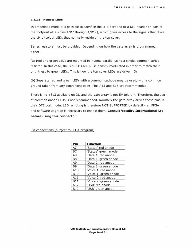
2.3.2.3 Remote LEDs
In embedded mode it is possible to sacrifice the DTE port and fit a 6x2 header on part of
the footprint of J8 (pins A/B7 through A/B12), which gives access to the signals that drive
the six bi-colour LEDs that normally reside on the top cover.
Series resistors must be provided. Depending on how the gate array is programmed,
either:
(a) Red and green LEDs are mounted in inverse parallel using a single, common series
resistor. In this case, the red LEDs are pulse density modulated in order to match their
brightness to green LEDs. This is how the top cover LEDs are driven. Or:
(b) Separate red and green LEDs with a common cathode may be used, with a common
ground taken from any convenient point. Pins A15 and B15 are recommended.
There is no +3v3 available on J8, and the gate array is not 5V tolerant. Therefore, the use
of common anode LEDs is not recommended. Normally the gate array drives these pins in
their DTE port mode. LED remoting is therefore NOT SUPPORTED by default - an FPGA
and software upgrade is necessary to enable them. Consult Vocality International Ltd
before using this connector.
Pin connections (subject to FPGA program)
Pin Function A7 'Status' red anode B7 'Status' green anode A8 'Data 1' red anode B8 'Data 1' green anode A9 'Data 2' red anode B9 'Data 2' green anode A10 'Voice 1' red anode B10 'Voice 1' green anode A11 'Voice 2' red anode B11 'Voice 2' green anode A12 'USB' red anode B12 'USB' green anode
V25 Multiplexer Supplementary Manual 1.0 Page 14 of 31

C H A P T E R 2 : I N S T A L L A T I O N
2.4 TIE-LINE mode
When either of the Voice Ports is configured to Tie-line mode, their
respective RJ45 port may be connected to an audio switch matrix or clean
feed monitor circuit. The port presents a 4-wire voice interface and a pair of
signals used to activate the channel. No ringing voltages are generated by,
or should be connected to the ports in Tie-line mode.
E&M is not supported by the V25 but each port has the equivalent of an ‘M’ circuit which may
be used to activate the connection to the remote unit under control of the “M-Lead Activation”
field on the System Menu.
The following diagram shows how the ‘M’ circuit is presented:
+3.3V
Schematic ‘M’ circuit
The current detector in the 'M' circuit has an internal impedance of 10K and is referenced
ignal internally to +3.3V. It can be stimulated by keying the ‘M’ lead to ground and the ‘MREF’ s
is provided for this purpose.
MREF
M
V25 Multiplexer Supplementary Manual 1.0 Page 15 of 31

C H A P T E R 3 : C O M P A R I S O N W I T H V 1 0 0
Chapter
33 Comparison with V100 The V25 shares many of the features and functionality provided by its older brother the V100.
However, some functionality has been changed. See Section 1.2 for a description of the
restrictions on the V25.
The table below compares some of the V100 and V25 features.
Feature V25 V100Supervisor port 6-pin locking mini-DIN 9-way D-type connector
Alarm port No Voltage-free changeover contacts
HSC port No Yes
LAN port Yes - 2 Yes - 1
Link port DTE only DTE or DCE
Data port DCE only DTE or DCE
USB port Host mode None
2 Maximum 8 or 16 depending on model
Voice/FAX channels
Voice ports FXS or Tie-line All voice ports can be configured as either FXS or FXO (depending on model) or Tie-line
Options cards available SVR only TDM, ISDN and E1
Software V25 build of Generic software Rev 4.0.5 or later
Standard V100 software dependant on hardware revision.
Feature keys Used to enable extra software features. Only PEP is available in the V25. See section 4.4
Used to enable extra software features. See the V100 Technical Manual for more information.
V25 Multiplexer Supplementary Manual 1.0 Page 16 of 31

C H A P T E R 4 : F E A T U R E S
Chapter
44 Features 4.1 Indicators
The V25 has six LED indicators on the lid for displaying the status of the unit as follows:
LED Red Green
Status Booting or fault Unit OKData 1,Data 2
Aggregate flashing: Carrier lostTributary: Errored packet sent/received
Aggregate solid: Carrier detectedAggregate flashing: Loop presentTributary: Good packet sent/received
Voice 1,Voice 2 N/A Channel activeUSB Fault condition Port active
4.2 Alarms
There is no summary alarm connector. Fault conditions are reported either visually by the LEDs
or via the management system, using the RS232 supervisor port or Telnet access.
4.3 Clocks
V25 data ports support the same pinouts as those on the V100 but only support a subset of
the functionality. Either may be used as an aggregate or as a tributary but Port 1(0:1) may
only be configured in DTE mode and Port 2(0:2) may only be configured in DCE mode. The
bigger products in the Vocality range all provide two reference buses known as GRX and GTX;
the V25 only supports GRX. These buses carry global clock reference signals and allow the unit
to derive phase-locked output clocks from a common input frequency. Since the V25 is
intended primarily for SOHO-style end-user applications, the implementation of just a single
reference bus is not considered a limitation.
V25 Multiplexer Supplementary Manual 1.0 Page 17 of 31

C H A P T E R 4 : F E A T U R E S
NOTE: By convention, the Receive Clock “RXC” is defined as “the clock associated with the
direction of data flow from aggregate to tributary” and the Transmit Clock “TXC” as “the clock
associated with the direction of data flow from tributary to aggregate”. This assumes that
aggregate ports are normally DTE presentation and tributaries are normally DCE, so for an
aggregate, RX data is input and TX data is output whereas for a tributary, RX data is output
and TX data is input.
The following table summarises the functionality available at each port:
Port Presentation RX Clock Sources TX Clock Sources0:1 DTE EXT EXT
TXC RXCPLL PLLDBA DBA
0:2 DCE EXT EXTTXC RXCPLL PLLDBA DBA
TTP (TT input, ST output from PLL)TTD (AS TTP but variable ST output)
Note that there is no longer a selection for “INT” or Internal. The V25 uses a VCXO for
derivation of clocks, which runs at a nominal 6.144MHz +/-25ppm with an adjustment range of
+/-100ppm and consequently any clocks that must be generated by the unit may now be
produced in PLL mode with considerable accuracy even without a reference input.
V25 Multiplexer Supplementary Manual 1.0 Page 18 of 31

C H A P T E R 4 : F E A T U R E S
The following definitions apply:
(i) “EXT”: The external interface
(ii) “TXC”: The channel TX clock
(iii) “PLL”: From the port’s RX Phase-locked Loop
(iv) “DBA”: From the port’s RX PLL as (iii), but the rate can be dynamically varied
(v) “RXC”: The channel RX clock
(vi) “TTP”: TXC PLL output mode where RXC input clock is sourced from TT
(vii) “TTD”: TXC DBA output mode where RXC input clock is sourced from TT
4.4 Software Feature Keys
The feature keys menu allows the entry of encrypted keys which enable enhanced features in
the V25. Two types of keys are supported – permanent keys are purchased to permanently
enable the features. Temporary keys are available to trial test a feature. They are active for up
to 24 hours or until the V25 is restarted. Please contact Vocality International to obtain the
appropriate keys for your units.
To enable a feature, move to the Key field, enter the key and press enter. The State changes
from LOCKED to UNLOCKED.
V25 Multiplexer Supplementary Manual 1.0 Page 19 of 31

C H A P T E R 5 A P P E N D I X A : S A F E T Y A N D A P P R O V A L S
Chapter
55 Appendix A : Safety and Approvals
WARNING:
This unit generates hazardous voltages.
There are no user-serviceable parts.
In the event of failure, the unit should only be repaired by qualified personnel or returned to
the factory.
WARNING: INSTALLATION OF EQUIPMENT
Any SELV 10/100base-T network plugs used - which could accidentally be plugged into the
telephone ports - must have their key tabs removed such that they can only be removed using
a special tool. This equipment must therefore only be professionally installed by suitably
trained service personnel.
WARNING: CONNECTION OF OTHER EQUIPMENT
This equipment allows connection only of suitably approved equipment to its ports, the safety
status of which is defined below.
SELV Ports:
i) Supervisor Port
ii) Data Ports
iii) LAN Port
iv) USB Port
The above named ports are classified as SELV (Safety Extra Low Voltage) in accordance with
V25 Multiplexer Supplementary Manual 1.0 Page 20 of 31

C H A P T E R 5 A P P E N D I X A : S A F E T Y A N D A P P R O V A L S
EN60950-1:2002, and must only be connected to equipment which similarly complies with the
SELV safety classification.
TNV2 Ports:
i) Voice ports (telephones or Tie-line connections) (when fitted)
The above named ports, classified as TNV2 (Telecom Network Voltage Type 2) in accordance
with EN60950-1:2002, generate TNV2 voltages. They must not be connected to any external
equipment also capable of generating TNV voltages.
Compliance with EMC emissions standards EN55022 and immunity standards EN50082-1 and
50082-2 is conferred by the host chassis. In order to meet the requirements of these
standards, the card must be operated with screened link, channel and supervisor cables.
Failure to do so may result in non-compliance.
WARNING: ESD PRECAUTIONS AND STATIC SENSITIVE CARD HANDLING
Vocality International Ltd. observe the general requirements of BS EN 100015-1 (1992) in all
matters relating to the handling and storage of electrostatic sensitive devices (ESDs) and
assemblies. We recommend strict observance of this standard during the installation of all
Option Cards.
All cards are assumed to contain at least one ESD and therefore all subassemblies containing
PCBs should be handled in the same way. Products are designed with protection components
on external and internal connectors where appropriate. User manuals, applications notes and
modification instructions contain warnings where an ESDs may become exposed to ESD. The
packaging of Vocality International Ltd. products is classified as secondary, for physical
protection only.
Cards should be handled in an ESD Protected Area (EPA) using approved materials (wrist
straps, bonding cords etc) from recognized suppliers.
ESDs should always be protected by primary packaging when moving between EPAs or EPA
and field sites. Equipment containing ESDs devices in primary packaging (e.g. the metal
enclosure) are moved off-site using additional secondary packaging for mechanical protection.
Within the EPA, cards should be stored in their primary packaging in electrostatic dissipative
bags.
V25 Multiplexer Supplementary Manual 1.0 Page 21 of 31

C H A P T E R 5 A P P E N D I X A : S A F E T Y A N D A P P R O V A L S
5.1 DECLARATIONS OF CONFORMITY
Vocality International Ltd, Lydling Barn, Lydling Farm, Puttenham Lane, Shackleford, Surrey GU8 6AP, UK
EC DECLARATION OF CONFORMITY
THIS IS TO CERTIFY:
V25 Multiplexer, manufactured byVocality International Ltd
CONFORMS WITH THE PROTECTION AND ELECTROMAGNETIC COMPATIBILITY
REQUIREMENTS OF THE FOLLOWING STANDARDS:
BS EN 60950-1: 2001 Safety Standard BS EN 61000-6-3: 2001 Emission Standard BS EN 55022 (conducted emissions) BS EN 55022 (radiated emissions) BS EN 61000-6-1: 2001 Immunity Standard
BS EN 61000-4-2 BS EN 61000-4-3 BS EN 61000-4-4 BS EN 61000-4-5 BS EN 61000-4-6 BS EN 61000-4-8 BS EN 61000-4-11
Signed ........................................ M.P.SAUNDERS (Group Technical Director)
Date ........................................
V25 Multiplexer Supplementary Manual 1.0 Page 22 of 31

C H A P T E R 5 A P P E N D I X A : S A F E T Y A N D A P P R O V A L S
FCC DECLARATION OF CONFORMITY
THIS IS TO CERTIFY:
V25 Multiplexer, manufactured byVocality International Ltd
COMPLIES WITH PART 15 OF THE FCC RULES. OPERATION IS SUBJECT TO THE FOLLOWING TWO
CONDITIONS:
(1) This device may not cause harmful interference and (2) This device must accept any interference received, including interference that
may cause undesired operation.
NOTE This equipment has been tested and found to comply with the limits for a class B digital device, pursuant to Part 15 of the FCC Rules. These limits are designed to provide reasonable protection against harmful interference in a residential installation. This equipment generates, uses and can radiate radio frequency energy and if not installed and used in accordance with the instructions, may cause harmful interference to radio communications. However, there is no guarantee that interference will not occur in a particular installation. If this equipment does cause harmful interference to radio or television reception, which can be determined by turning the equipment off and on, the user is encouraged to try to correct the interference by one or more of the following measures:
(a) Reorient or relocate the receiving antenna. (b) Increase the separation between the equipment and the receiver (c) Connect the equipment into an outlet on a circuit different from that to which the
receiver is connected. (d) Consult the dealer or an experienced radio technician for help.
Signed ........................................ M.P.SAUNDERS (Group Technical Director)
Date ........................................
V25 Multiplexer Supplementary Manual 1.0 Page 23 of 31

C H A P T E R 6 A P P E N D I X B : P I N A S S I G N M E N T S
Chapter
66 Appendix B: Pin Assignments 6.1 Supervisor Cable
RS232/V.24 STRAIGHT 5-way Multiplexer Supervisor DCE to Terminal DTE Cable
(Part Number VI68224A) MUX 5-way Male
Mini-DIN Connector Terminal 9-way
Female Connector UNC 4/40 Screws
Signal Name Signal Type (at mux end)
Shield Shield SHIELD SHIELD1 2 RXD Output 6 3 TXD Input 3 5 GND Ground
Notes:
� Cable type: Belden 3 separate conductors, overall screen (or equivalent). Maximum length 5 metres.
V25 Multiplexer Supplementary Manual 1.0 Page 24 of 31

C H A P T E R 6 A P P E N D I X B : P I N A S S I G N M E N T S
6.2 Data Ports
Both data ports are presented with a DB15F HD interface:
Pin # Signal Name DTE DCE V.11 RS449 V.35 RS530 V.24
Shield Shield Shield Shield Shield Shield C C 1 GND GND GND GND GND C C 2 T(A) SDA SDA SDA TXD O I9 T(B) SDB SDB SDB - O I3 C(A) RTSA DTR RTSA DTR O I
10 C(B) RTSB - RTSB - O I 4 R(A) RDA RDA RDA RXD I O
11 R(B) RDB RDB RDB - I O 5 I(A) RRA DCD RRA DCD I O
12 I(B) RRB - RRB - I O 6 S(A) RTA SCRA SCRA RXC I O
13 S(B) RTB SCRB SCRB - I O 7 - STA SCTA SCTA TXC I O
14 - STB SCTB SCTB - I O8 - TTA SCTEA SCTEA EXTXC O I
15 - TTB SCTEB SCTEB - O I
6.3 Analogue Voice Ports
8-way RJ45-Type Analogue voice port Pin Connections
4-wire Tie-line mode 2-wire FXS/FXO mode Pin No. Signal Name Signal Type Name Type
1 MREF Reference GND - - 2 RX+ Input - - 3 RX- Input - - 4 - - TIP Input/Output5 - - RING Input/Output6 TX+ Output - - 7 TX- Output - - 8 M Current Sense - -
WARNING:
LINE VOLTAGES ARE PRESENT ACROSS TIP AND RING ON FXS CONNECTIONS. CONNECT ONLY TELEPHONE APPLIANCES TO THESE PINS. DAMAGE COULD RESULT TO CUSTOMER EQUIPMENT.
V25 Multiplexer Supplementary Manual 1.0 Page 25 of 31

C H A P T E R 6 A P P E N D I X B : P I N A S S I G N M E N T S
6.4 10/100base-T Ports
8-way RJ45 10/100base-T Port Connections
Pin No. Signal Name Signal Type 1 TX+ Input 2 TX- Input 3 RX+ Output 4 Shield - 5 Shield - 6 RX- Output 7 Shield - 8 Shield -
6.5 JP3 Parallel Host Expansion Connector
Host Port Connector JP3 Pin No.
Signal Name
Signal Type Pin No.
Signal Name Signal Type
1 +5V Power from host 2 +5V Power from host3 GND 4 GND 5 BS_B0# Output 6 NC 7 GEN12 General I/O 8 GEN0 General I/O 9 GEN13 General I/O 10 GEN1 General I/O
11 GEN14 General I/O 12 GEN2 General I/O 13 GEN15 General I/O 14 GEN3 General I/O 15 GEN16 General I/O 16 GEN4 General I/O 17 GEN17 General I/O 18 GEN5 General I/O 19 GEN18 General I/O 20 GEN6 General I/O 21 GEN19 General I/O 22 GEN7 General I/O 23 GEN20 General I/O 24 GEN8 General I/O 25 GEN21 General I/O 26 GEN9 General I/O 27 GEN22 General I/O 28 GEN10 General I/O 29 GEN23 General I/O 30 GEN11 General I/O 31 BS_B1# Output 32 SER_CLKIN I/O 33 R/W# Output 34 SER_DATOUT I/O 35 GPL_A1_H Output 36 SER_SVO I/O 37 CS_H# I/O 38 SER_ETCIN I/O 39 +5V Power from host 40 +5V Power from host41 GND 42 GND 43 PCMCLK_H I/O 44 N/C -45 PCMFS_H I/O 46 SER_DATIN I/O 47 SER_CLKOUT I/O 48 SER_SYNOUT I/O
This connector presents generic signal lines to permit customization to specific interface
requirements. Refer to Vocality for details of DC and AC characteristics of these signals.
V25 Multiplexer Supplementary Manual 1.0 Page 26 of 31
C H A P T E R 6 A P P E N D I X B : P I N A S S I G N M E N T S
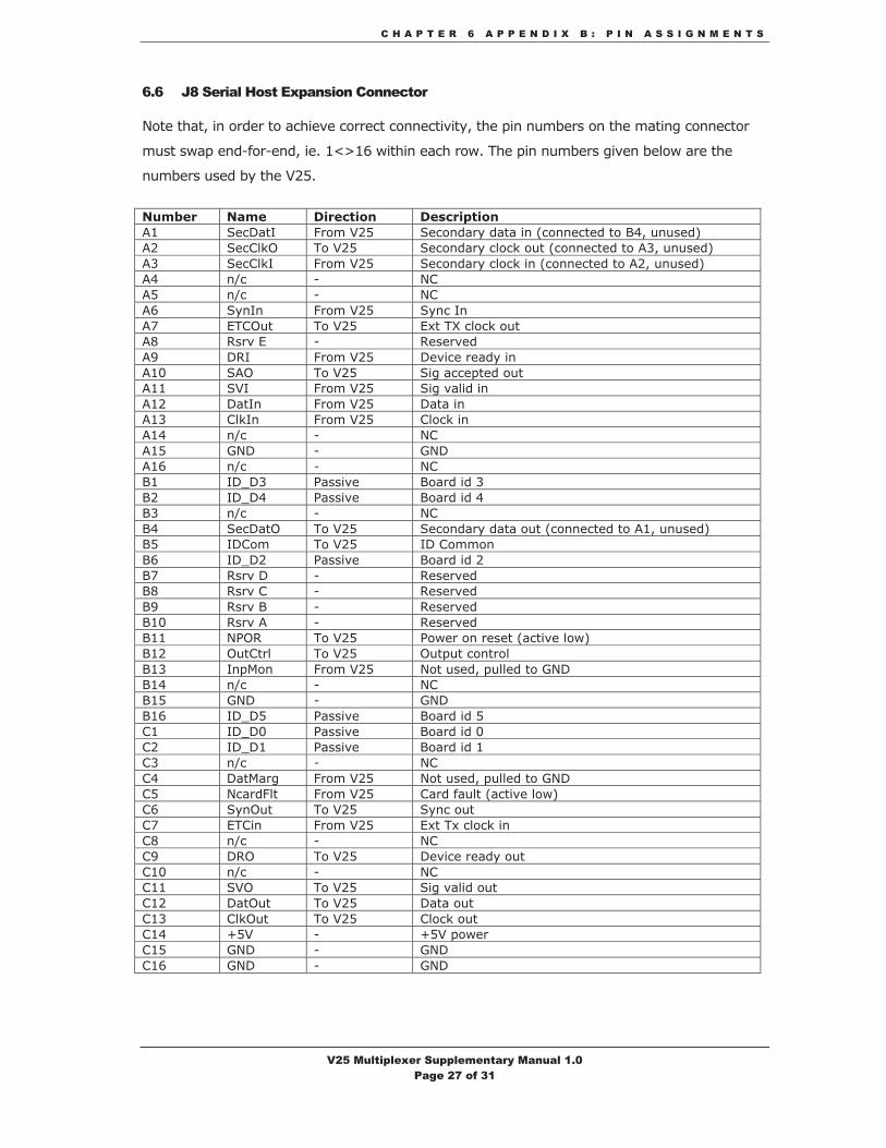
6.6 J8 Serial Host Expansion Connector
Note that, in order to achieve correct connectivity, the pin numbers on the mating connector
must swap end-for-end, ie. 1<>16 within each row. The pin numbers given below are the
numbers used by the V25.
Number Name Direction Description A1 SecDatI From V25 Secondary data in (connected to B4, unused) A2 SecClkO To V25 Secondary clock out (connected to A3, unused) A3 SecClkI From V25 Secondary clock in (connected to A2, unused) A4 n/c - NCA5 n/c - NCA6 SynIn From V25 Sync In A7 ETCOut To V25 Ext TX clock out A8 Rsrv E - Reserved A9 DRI From V25 Device ready in A10 SAO To V25 Sig accepted out A11 SVI From V25 Sig valid in A12 DatIn From V25 Data in A13 ClkIn From V25 Clock in A14 n/c - NCA15 GND - GNDA16 n/c - NCB1 ID_D3 Passive Board id 3 B2 ID_D4 Passive Board id 4 B3 n/c - NCB4 SecDatO To V25 Secondary data out (connected to A1, unused) B5 IDCom To V25 ID Common B6 ID_D2 Passive Board id 2 B7 Rsrv D - Reserved B8 Rsrv C - Reserved B9 Rsrv B - ReservedB10 Rsrv A - Reserved B11 NPOR To V25 Power on reset (active low) B12 OutCtrl To V25 Output control B13 InpMon From V25 Not used, pulled to GND B14 n/c - NCB15 GND - GNDB16 ID_D5 Passive Board id 5 C1 ID_D0 Passive Board id 0 C2 ID_D1 Passive Board id 1 C3 n/c - NCC4 DatMarg From V25 Not used, pulled to GND C5 NcardFlt From V25 Card fault (active low) C6 SynOut To V25 Sync out C7 ETCin From V25 Ext Tx clock in C8 n/c - NCC9 DRO To V25 Device ready out C10 n/c - NCC11 SVO To V25 Sig valid out C12 DatOut To V25 Data out C13 ClkOut To V25 Clock out C14 +5V - +5V power C15 GND - GNDC16 GND - GND
V25 Multiplexer Supplementary Manual 1.0 Page 27 of 31

C H A P T E R 7 A P P E N D I X C : S P E C I F I C A T I O N S
Chapter
77 Appendix C: Specifications
Data Ports Number 2
Presentation Port 1 DTE(Aggregate), Port 2 DCE(Tributary)
Interface Selectable V.24/RS232, V.11, V.35, RS422, V.36, RS449 on DB15HD Female
Format Synchronous Transparent/HDLC or Asynchronous
Data Rates Sync: 50bps to 5.12Mbps
Async: 50, 75, 300, 600, 1200, 2400, 4800,
9600, 19200, 38400, 57600, 115200bps
Selected word structure combinations with optional error-correction and compression
Clock sources See text
Analogue voice/FAX Number 2
Presentation 8-way RJ45
Interface 2-wire FXS for connection to telephone/trunk port with ring voltage/cadence generation and dial pulse/ring trip detection
4-wire Tie-line with activation input
Compression G.723.1 (5.3/6.3Kbps MP-MLQ),
G.729 Annex A (8Kbps CS-ACELP),
G.726 (16-40Kbps ADPCM),
G.727 (16-40Kbps E-ADPCM),
G.711 (64Kbps PCM) µ-law or A-law
Proprietary NetCoder® (6.4,7.2,8.0,8.8,9.6Kbps)
Relays Group 3 FAX relay at 2400-14400bps
V.32bis Modem relay up to 14400bps
STU-III Secure Voice Relay by Option Card
Signalling MFR1, R1, R2, SS4, SS5, AC15, Call Progress
V25 Multiplexer Supplementary Manual 1.0 Page 28 of 31

C H A P T E R 7 A P P E N D I X C : S P E C I F I C A T I O N S
Echo canceller G.168 adaptive (16/32mS tail)
Coding delay Per algorithm
Gain ±31dB programmable in 1dB steps
IP Router Ports Number 2
Presentation 10/100base-T on RJ45 Ethernet, Auto-MDIX
Facilities IPV4 Static Router with DHCP Server/Relay
USB Port Number 1
Presentation USB-II @ 12Mbps on ‘A’ type connector
Mode Host
Supervisor Presentation 6-way locking mini-DIN
Interface V.24/RS232 serial
Format Asynchronous
Data Rate 9600bps, 8 bits, no parity, one stop bit
Flow Control None
Mode Formatted terminal display or Teletype M&C
Emulations Automatic support of most common terminals
Physical Indicators 6 Red/Green LED indicators, remote connection available
Dimensions 175mm x 80mm x 40mm
Weight 450g
Environment Operating: 0-50degC, 0-90%RH non-condensing
Storage: -40degC to +85degC
Power Supply 9-18VDC @2.0A
Max Power <10W
V25 Multiplexer Supplementary Manual 1.0 Page 29 of 31

C H A P T E R 8 A P P E N D I X D : P A R T C O D E S
Chapter
88 Appendix D: Part Codes
V25 Multiplexer VI68400
V25 External PSU Module VI68403
V25 Supervisor Cable VI68224B
Software Feature – PEP VI68400/SWF/PEP
V25 Multiplexer Supplementary Manual 1.0 Page 30 of 31

C H A P T E R 9 A P P E N D I X E : A B B R E V I A T I O N S
Chapter
99 Appendix E: Abbreviations
Agg Aggregate Port ARP Address Resolution Protocol Bps(Kbps) Bits per Second (Kilobits per second) CIR Committed Information Rate DBA Dynamic Bandwidth Allocation DHCP Dynamic Host Configuration Protocol DNS Domain Name Service GRX Global Receive Clock GTX Global Transmit Clock ICMP Internet Control Message Protocol IETF Internet Engineering Task Force IP Internet Protocol LAN Local Area Network LDN Local Directory Number MAC Media Access Control MTU Maximum Transmission Unit (bytes) PEP Performance Enhancing Proxy PLL Phase-Locked Loop QoS Quality of Service RFC Request For Comments RXC Receive Clock RXD Receive Data STP Spanning Tree Protocol TCP Transmission Control Protocol TCPGw TCP Gateway TFTP Tiny File Transfer Protocol TOS Type of Service Trib Tributary port TXC Transmit Clock TXD Transmit Data UDP User Datagram Protocol UDPGw UDP Gateway WAN Wide Area Network
V25 Multiplexer Supplementary Manual 1.0 Page 31 of 31