Technical Specifications San Diego Gas & Electric Co ...
84
Revision 4/15/2015 SDGE Technical Specifications San Diego Gas & Electric Co. Solar Energy Project Final Prepared by Sacramento, CA San Diego, CA Portland, OR
Transcript of Technical Specifications San Diego Gas & Electric Co ...

Revision 4/15/2015 SDGE
Technical Specifications
San Diego Gas & Electric Co.
Solar Energy Project
Final Prepared by
Sacramento, CA
San Diego, CA
Portland, OR

2
SDG&E Tech Spec – Final
Contents
1 SCOPE OF WORK ................................................................................................................... 7
1.1 PURPOSE ....................................................................................................................... 7
1.2 SUMMARY ..................................................................................................................... 7
1.2.1 General System Description ...................................................................................... 7
1.2.2 Site and Facility Descriptions .................................................................................... 7
1.2.3 System Equipment and Accessories ........................................................................... 8
1.2.4 Site Environmental Approval Support Services ............................................................ 8
1.2.5 Engineering Design Services ..................................................................................... 9
1.2.6 Work Provided by SDGE ........................................................................................... 9
1.2.7 Documentation Submittals ....................................................................................... 9
1.2.8 Procurement Services .............................................................................................10
1.2.9 Testing ..................................................................................................................10
1.2.10 Equipment Documentation Services .........................................................................10
1.2.11 Project Management Services ..................................................................................10
1.2.12 Construction Management Services .........................................................................11
1.2.13 Manufacturers Field Representatives Services ...........................................................11
1.2.14 Additional Equipment and Equipment Services ..........................................................11
1.2.15 Operation and Maintenance Services .......................................................................12
1.3 OVERALL SYSTEM AND PROJECT CONFIGURATION .........................................................13
1.4 SITE-SPECIFIC CONDITIONS .............................................................................................13
1.4.1 Climate Conditions .................................................................................................13
1.4.2 Seismic and Geotechnical Conditions ........................................................................13
1.4.3 Electrical and Communications Interconnections .......................................................14
1.5 PERFORMANCE REQUIREMENTS ...................................................................................14
1.5.1 Design Life ............................................................................................................14
1.5.2 Typical Inverter Description ...................................................................................14
1.5.3 Operation and Maintenance ....................................................................................15
1.6 CODES, STANDARDS, AND SPECIFICATIONS ...................................................................15
1.7 BANNED MATERIALS ....................................................................................................17
2 CIVIL AND STRUCTURAL REQUIREMENTS ................................................................................18
2.1 GENERAL .....................................................................................................................18
2.2 CIVIL REQUIREMENTS ...................................................................................................18
2.2.1 Surveying ..............................................................................................................18

3
SDG&E Tech Spec – Final
2.2.2 Excavating and Trenching ......................................................................................18
2.2.3 Backfilling ..............................................................................................................19
2.2.4 Grading .................................................................................................................19
2.2.5 Access Roads ........................................................................................................19
2.2.6 Perimeter Fence ...................................................................................................20
2.2.7 Perimeter Road and Module Row Spacing ..............................................................21
2.2.8 Security ................................................................................................................21
2.2.9 Storm Water Management ....................................................................................21
2.2.10 Vegetation Replacement/Landscaping ...................................................................21
2.2.11 Standard Urban Storm Water Mitigation Plan.........................................................22
2.3 STRUCTURAL DESIGN ...................................................................................................22
2.3.1 General ................................................................................................................22
2.3.2 Foundations ..........................................................................................................22
2.3.3 Design Loads .........................................................................................................23
2.3.4 Mounting Structures and Structural Steel ...............................................................23
2.3.5 Structural Concrete ...............................................................................................24
2.3.6 Shade Structure ....................................................................................................24
2.3.7 Communications Enclosure ...................................................................................25
2.3.8 Permits .................................................................................................................25
2.3.9 Signs and Labels ....................................................................................................25
2.3.10 Testing .................................................................................................................26
3 MECHANICAL SYSTEMS AND EQUIPMENT ...............................................................................27
3.1 FIRE PROTECTION SYSTEM ............................................................................................27
4 ELECTRICAL SYSTEMS AND EQUIPMENT ...............................................................................28
4.1 GENERAL .....................................................................................................................28
4.1.1 Interconnections ...................................................................................................28
4.1.2 Design Criteria ......................................................................................................28
4.2 EQUIPMENT .................................................................................................................29
4.2.1 Photovoltaic (PV) Modules ....................................................................................29
4.2.2 Inverters ...............................................................................................................30
4.2.3 Station Batteries...................................................................................................31
4.2.4 Step Up Transformers ...........................................................................................32
4.2.5 Communications Enclosure ...................................................................................33
4.2.6 Medium Voltage Switchgear ..................................................................................33
4.2.7 Power Cables ........................................................................................................34
4.2.8 Combiner Boxes ....................................................................................................34
4.2.9 Disconnecting Means ............................................................................................34

4
SDG&E Tech Spec – Final
4.2.10 Conduit and Fittings ..............................................................................................34
4.2.11 Electrical Equipment Enclosures ...............................................................................35
4.3 ELECTRICAL PROTECTION .............................................................................................35
4.3.1 General ................................................................................................................35
4.3.2 Protection Systems ...............................................................................................35
4.4 METERING ...................................................................................................................36
4.4.1 Revenue Metering ................................................................................................36
4.4.2 Indication Metering ................................................................................................36
4.5 GROUNDING ................................................................................................................37
4.5.1 General ................................................................................................................37
4.6 PROJECT ELECTRICAL SERVICES .....................................................................................37
4.6.1 Lighting Systems ...................................................................................................37
4.6.2 Convenience Receptacles ......................................................................................38
4.6.3 Video Monitoring Systems .....................................................................................38
5 SYSTEM CONTROLS AND COMMUNICATIONS ..........................................................................40
5.1 GENERAL .....................................................................................................................40
5.1.1 System Description .................................................................................................40
5.2 METEOROLOGICAL STATION .........................................................................................40
5.3 I/O DATA POINTS .........................................................................................................40
5.3.1 Communications Enclosure ...................................................................................41
5.3.2 VDC System ..........................................................................................................41
5.3.3 AC Revenue Meter Points per Utility Metering Standards .......................................41
5.3.4 PV Modules ..........................................................................................................41
5.3.5 Inverters ...............................................................................................................41
5.3.6 Switchgear ............................................................................................................42
5.3.7 Isolation Disconnect ...............................................................................................42
5.4 QUALITY ASSURANCE/QUALITY CONTROL .....................................................................43
5.4.1 Quality Control Program ........................................................................................43
5.5 CIVIL/STRUCTURAL/ARCHITECTURAL ............................................................................43
5.5.1 Sitework, Excavation, Fill and Grading ....................................................................43
5.5.2 Concrete ...............................................................................................................43
5.5.3 Grouting ...............................................................................................................44
5.5.4 Grout Mixes ..........................................................................................................44
5.5.5 Structural and Miscellaneous Steel ........................................................................44

5
SDG&E Tech Spec – Final
5.6 ELECTRICAL ..................................................................................................................44
5.6.1 General ................................................................................................................44
5.6.2 Panelboards ..........................................................................................................44
5.6.3 Control Panels and Consoles ..................................................................................45
5.6.4 Fire Alarm .............................................................................................................45
5.6.5 Lightning Protection ...............................................................................................45
5.6.6 Cathodic Protection ................................................................................................45
5.6.7 Grounding .............................................................................................................45
5.6.8 Cable Installation....................................................................................................46
5.6.9 Cable and Electrical Equipment Terminations ............................................................47
5.7 ELECTRICAL IDENTIFICATION ..........................................................................................48
5.7.1 General Requirements ..........................................................................................48
5.7.2 Cable and Wire Labels ...........................................................................................48
6 ENVIRONMENT, SAFETY, AND HEALTH .................................................................................49
6.1 PURPOSE .....................................................................................................................49
7 DOCUMENTATION AND SUBMITTALS ...................................................................................50
7.1 GENERAL DOCUMENTS AND SUBMITTALS .....................................................................50
7.2 SUBMITTAL FORMAT AND COPIES ................................................................................50
7.3 SUBMITTAL CRITERIA ...................................................................................................51
7.3.1 Submittal Recipient ................................................................................................51
7.3.2 Submittals for SDGE Review and Approval ..............................................................51
7.4 O&M MANUAL .............................................................................................................52
7.5 QUALITY ASSURANCE MANUAL .....................................................................................54
8 PERFORMANCE MODELING AND ANALYSIS REQUIREMENTS .................................................55
8.1 INTRODUCTION .............................................................................................................55
8.2 REQUIREMENTS ............................................................................................................55
9 STARTUP AND COMMISSIONING ..........................................................................................59
9.1 INTRODUCTION ............................................................................................................59
9.2 General START-UP AND COMMISSIONING SCOPE OF SERVICES ......................................59
9.2.1 General ................................................................................................................59
9.2.2 Mechanical ...........................................................................................................59
9.2.3 Electrical ...............................................................................................................59
9.2.4 Instrumentation ....................................................................................................60

6
SDG&E Tech Spec – Final
9.3 COORDINATION AND NOTIFICATION ...............................................................................60
9.3.1 Coordination ..........................................................................................................60
9.4 TURNOVER PACKAGES ..................................................................................................61
9.4.1 Preparation ..........................................................................................................61
9.4.2 Issuance ...............................................................................................................62
9.4.3 Documentation .....................................................................................................62
9.5 POST-COMMISSIONING CHECKOUT ..............................................................................63
9.5.1 System Checkout ..................................................................................................63
9.5.2 On-Line Operational Checks ...................................................................................64
9.6 ACCEPTANCE TESTING ..................................................................................................64
9.6.1 Definitions .............................................................................................................64
9.6.2 Power Output Test and Annual Test Overview ..........................................................66
9.6.3 Energy Production Guarantee ................................................................................67
9.6.4 Pre-Test Activities .................................................................................................67
9.6.5 Power Output Test ................................................................................................68
9.6.6 Test Measurements ..............................................................................................70
9.6.7 Test Calculations ...................................................................................................72
9.6.8 Test Reporting ......................................................................................................73
9.6.9 Power Output Degradation Monitoring ..................................................................73
9.6.10 Energy Production Test .........................................................................................74
9.6.11 Annual Energy Production Test Procedures ............................................................75
Attachment 1: Minimum System Performance Requirements ...................................................77
Attachment 2: Site Conditions .................................................................................................78
Attachment 3: Approved Equipment Manufacturer List ............................................................79
Attachment 4: Photovoltaic Module Requirements ..................................................................80

7
SDG&E Tech Spec – Final
1 SCOPE OF WORK
1.1 PURPOSE
This technical specification (Specification) is intended to define the minimum requirements which will
form the basis for the detailed design, engineering, procurement, construction, and commissioning of a
complete photovoltaic power system (System), as well as the supporting accessories, interconnections,
and infrastructure as described herein (the Project). These Specifications are not intended to be all-
inclusive, but should provide sufficient detail to enable the preparation and execution of a fixed-price
Agreement to fulfill the described scope of work (Work). Any deviations from these criteria must be
approved, in writing, by San Diego Gas and Electric Company (SDGE). The criteria herein have been
formulated to ensure that the System design, engineering, procurement, construction, and
commissioning will meet the following goals:
Provide for a safe construction and operating environment
Provide quality construction and equipment selection to ensure efficient operation
Optimize initial capital costs to minimize overall life-cycle costs
Provide convenient access to equipment to ensure ease of maintenance
Maximize System performance through equipment layout and selection
Utilize environmentally sound practices.
Be constructed of non-combustible materials to the maximum extent practicable
Provide comprehensive design, engineering, construction, and commissioning documents to
SDGE for their records
1.2 SUMMARY
1.2.1 General System Description
The System will consist of ground mounted fixed-tilt systems with attached photovoltaic (PV) modules
located on each Site. The PV modules will be connected to one or more inverters with an individual net
AC output of 100kW to 1,000kW. The System will have one interconnection between the inverter(s) and
the associated utility substation via a step-up transformer at each Site. Refer to Attachment 1,
Minimum System Performance Requirements for minimum performance requirements.
The Seller shall be responsible for the complete design, procurement, construction, and commissioning
of a complete PV System with accessories and all supporting work (Project), except as specifically
excluded in these documents.
1.2.2 Site and Facility Descriptions
The System will be constructed on the following site(s) (Site).

8
SDG&E Tech Spec – Final
Property Name Facility Nameplate Capacity
(kWDC STC)1
Jurisdiction Interconnection
Point
¹For DC to AC conversion, use 0.85
1.2.3 System Equipment and Accessories
The following list is not all inclusive but summarizes the common items expected to be procured and
installed by the Contractor as part of the complete System:
1. PV modules
2. PV module support system
3. Combiner boxes
4. Electrical disconnects
5. Inverter(s) with enclosures and/or shade structures
6. System electrical protection
7. Switchgear
8. Revenue grade AC metering
9. Metrological (MET) stations
10. Control and monitoring systems
11. Communications Enclosure
12. Outdoor rated equipment enclosures
13. Cables, wires, jumpers, connectors, system grounding and associated trenching and/or boring
14. Equipment foundations
15. Lighting
16. Signage
17. Security fencing with access gates
1.2.4 Site Environmental Approval Support Services
The Seller shall be solely responsible for appropriately documenting and providing necessary
environmental evaluation of each Site through the California Environmental Quality Act (CEQA) process

9
SDG&E Tech Spec – Final
and complying with all requirements, restrictions, reports, and actions required for the Project to be
completed. The impact and scope of the CEQA process will depend on various factors specific to each
Site, and will be at the discretion and best judgment by the Seller as to the extent of the Project type
and if categorical exemptions or a negative declaration may be applied to a Site. Upon review of the
environmental significance at the Site, the Seller shall then be responsible for the full implementation of
the CEQA process including, but not limited to, public notices, report and plans, form submittals,
presentations, and all other contact with the Lead Agency, or Authority Having Jurisdiction..
1.2.5 Engineering Design Services
The Seller shall be solely responsible for the detailed design and coordinated functioning of all goods,
equipment and material furnished under this Specification. The Seller shall conform to industry standard
engineering practice for the operating conditions specified. All component parts of the equipment shall
be so designed as to facilitate correct and ready field assembly, maintenance and servicing operation;
and to ensure their proper coordinated functioning and operation.
1.2.6 Work Provided by SDGE
Seller will be responsible for building the generation and interconnection from each Site’s main step-up
transformer(s) to the Point of Interconnection (POI). As part of the Distribution System Upgrades,
SDG&E will procure and install a SCADA-controlled 12kV main circuit breaker at the POI. SDG&E will also
install portions of the Telemetering, as described in the SDG&E Electric Distribution Interconnection
Handbook. The cost of the system upgrade work will be charged to the Seller as part of the Project cost.
The Electric Distribution Handbook can be accessed at http://sdge.com/documents/distribution-
interconnection-handbook.
1.2.7 Documentation Submittals
The following list is not all inclusive but defines the Project documents that are required to be submitted
by the Seller for review and approval by SDGE. Time periods and dates for documentation submittals
shall be in compliance with those defined in the BTO Agreement. At the Seller’s option, documentation
may be submitted earlier than the dates listed.
1. Copy of the Approved Major Use or Administrative permit from the Authority having Jurisdiction
(AHJ) including all documents submitted for the permit together with the ruling and the
conditions from the AHJ.
2. Copy of the Approved Building Permit from the AHJ with plan documentation and all required
submittals,
3. As-Builts (Record Drawings)
4. O&M Manual with specifications, startup, commissioning and testing procedures for relevant
equipment
5. Final PV syst Model of the System and system power production calculations based on the site.

10
SDG&E Tech Spec – Final
6. Turnover package and test documentation
7. Professional Engineer Wet Stamps and signatures on final design documents:
1.2.8 Procurement Services
The Seller shall be responsible for delivery to the Site of all equipment and materials procured
by the Seller for completion of the Project.
.
1.2.9 Testing
All equipment provided under this Specification shall be tested to demonstrate the ability to operate
under the conditions as set forth in this Specification and to fulfill all warranties, guarantees and
requirements. If the tests indicate that the equipment fails to meet the Minimum System Performance
Requirements or other specified requirements, the Seller shall correct any defects in accordance with
the procedures stated in the Agreement and this Specification.
1.2.10 Equipment Documentation Services
The Seller shall provide the following product supporting documents:
Spare Parts Lists. The Seller shall provide all commissioning and start-up spares and parts as
necessary. In addition, as part of the procurement process the Seller shall obtain recommended
operational spare parts from each vendor. The Seller shall incorporate this into a recommended
Spare Parts List for each item of equipment..
Special Tools List. The Seller shall provide all special tools and other items necessary for
commissioning, start-up, dismantling of equipment, and on-going maintenance requirements for
the duration of the System. In addition, as part of the procurement process, the Seller shall
obtain a price for all special tools required from each vendor. The Seller shall incorporate this
into a recommended Special Tools List for each item of equipment. .
Engineering Data Submittals: The Seller shall submit drawings and engineering data in
accordance with the schedule.
Operation & Maintenance Manuals. The Seller shall furnish O&M Manuals for all equipment and
systems within the System prior to start-up and commissioning.
1.2.11 Project Management Services
The Seller shall provide project management services:
Time is of the essence in completion of the Work. This includes the completion of various
activities in accordance with milestone dates in addition to the timely delivery of equipment and
materials. The Seller is solely responsible for developing and maintaining a schedule to meet all
contractual milestone dates provided in the Agreement.

11
SDG&E Tech Spec – Final
The Seller may request meetings with SDGE at any time during the project in order to expedite
the Work.
After the Effective Date of the Agreement, the Seller shall provide to SDGE a proposed design,
manufacturing, and shipping schedule indicating the proposed plan to meet the Project’s
scheduled milestone dates. This Schedule shall be delivered to SDGE no more than one (1) week
from Effective Date. The Schedule shall be updated and submitted by the first of each month.
1.2.12 Construction Management Services
On-Site Manager: The Seller shall provide his own Construction Manager who shall be
responsible for coordinating the activities of the Seller’s personnel and that of all
Subcontractors..
The SDGE Project Manager and their Independent Engineer will be allowed on site at any time,
with prior notification to the Seller’s Construction Manager, to review work and/or testing.
1.2.13 Manufacturers Field Representatives Services
The Seller shall provide manufacturers’ field representatives for certification of the condition of
equipment prior to initial operation. Representatives shall be technically competent, factory-trained,
experienced in the installation and operation of the equipment under each representative's jurisdiction,
and authorized by the equipment manufacturer to perform the work stipulated for equipment
certification.. Representatives shall furnish written certification to SDGE’s Program Manager that the
equipment has been inspected and adjusted by them or under their direction and supervision and that it
is ready for service. This certification shall be completed before initial operation of the equipment.
1.2.14 Additional Equipment and Equipment Services
The Seller shall provide the following equipment and equipment services in addition to the equipment
directly required for the Project:
Any special tools required for maintenance or dismantling of the equipment provided
All test equipment and services for checkout and calibration of all control, metering,
instrumentation, and protective devices
Testing and start-up services for all electrical and control systems. Testing shall include all pre-
operational functional tests, equipment calibration, and insulation resistance tests.
Lawful disposal of all chemicals and waste material resulting from work under these
specifications
All miscellaneous consumable materials, including weld filler rod, sealants, solvents, joint
compounds, and other items required to erect the System

12
SDG&E Tech Spec – Final
Primer and/or finishing paint and application services for material and equipment furnished and
erected under this Agreement in accordance with these Specifications
Vendor recommended spare parts such as fuses and filters for operation & maintenance.
1.2.15 Operation and Maintenance Services
The Seller, as part of the construction scope, shall provide all necessary operational and maintenance
services recommended by the various equipment manufacturers during the construction, testing, and
startup period. Following project completion, acceptance, and turnover, and the contractor shall
provide ongoing services as detailed in the BTO document.
END OF SECTION

13
SDG&E Tech Spec – Final
PROJECT DESIGN BASIS
1.3 OVERALL SYSTEM AND PROJECT CONFIGURATION
The System will consist of ground mounted fixed-tilt rack systems with attached PV modules located at
each Site. The modules will be connected together in series to form strings which will produce DC power
at 1,000V (or highest voltage allowed by Authority Having Jurisdiction) or less. The DC power generated
by PV panels will be collected and converted to AC by photovoltaic inverters. The inverters will have a
typical net AC output of 100kW to 1,000kW. The System will have one interconnection between the
step-up transformer and the associated substation switchgear at each Site. All equipment shall be
supplied in accordance with Attachment 3, Approved Equipment Manufacturer List.
All types of PV module technologies are acceptable provided that they meet the requirements
described in Attachment 4, Photovoltaic Module Requirements.
The overall Project consists of the PV System and all supporting equipment and structures. The panel
arrays shall be arranged to allow for convenient maintenance of the panels, inverters, modules,
transformers, etc., and for the optimal power generation capability of the Project.
The site will have access via a gravel perimeter road and internal gravel roads as required for ease of
inspection and maintenance. The entire site will be surrounded by a security fence.
As a minimum, the design of the System and Project shall conform to all of the requirements of this
Specification in its entirety.
1.4 SITE-SPECIFIC CONDITIONS
1.4.1 Climate Conditions
The System shall be designed for start-up, shutdown, and continuous operation throughout the full
range of weather conditions and temperatures as shown in the general Site data included in Attachment
2, Site Conditions. Seller to provide specific hourly climatic data to SDGE as a Typical Meteorological
Year 3 (TMY3) file for design purposes.
All structures and equipment included in the Project shall be designed for outside location and for the
normal annual cycle of ambient conditions typical to the Project location. The Seller shall provide a
shade structure to cover the inverters, switchgear, disconnects, and other similar electrical equipment.
1.4.2 Seismic and Geotechnical Conditions
A site specific Geotechnical Report shall be prepared for the Project by a Geotechnical Engineer with
current registration in California, at the expense of the Seller. The Seller is responsible for the overall
geotechnical design basis of the Project.

14
SDG&E Tech Spec – Final
All seismic requirements shall be detailed in the above Geotechnical Report. The Project shall be
designed in accordance with the specified seismic design values per all applicable Codes, including the
California Building Code (CBC).
1.4.3 Electrical and Communications Interconnections
The System will be electrically connected to the associated substation switchgear. The System
communication shall interface with the SDGE’s existing communication network.
1.5 PERFORMANCE REQUIREMENTS
1.5.1 Design Life
The System and its components shall be designed for a minimum life of twenty-five (25) years.
1.5.2 Typical Inverter Description
The inverter(s) shall convert the DC electricity generated by the PV modules into AC electricity. The
California Energy Commission (CEC) weighted efficiency of the inverter shall be greater than or equal to
96.5%. The inverter shall have integrated Maximum Power Point Tracking (MPPT) and AC and DC
disconnects
Minimum Performance Requirements
Seller shall design and install a system with a total Nameplate Rated Capacity as specified in
Attachment 1, Minimum System Performance Requirements. Aggregate Nameplate Capacity of
installed modules shall be no less than 100% of Project Nameplate Capacity.
Nameplate Rated Capacity shall be calculated using the PV panel nameplate ratings at standard
temperature conditions (STC).The System shall be designed to the following Minimum System
Performance Requirements:
1. The Actual System Performance shall be equal to or greater than ninety-three percent (93%) of
the Expected System Performance determined in the performance modeling, at STC-DC.
2. The Maximum System Losses as defined in 9.6.1, from and including PV panels through the
System revenue meter shall not exceed fifteen percent (15%).
The Seller shall be responsible for designing, procuring, constructing, testing, and commissioning of the
complete System. The Seller shall also perform the modeling and analysis requirements of Section 8,
Performance Modeling and Analysis Requirements.
As part of the testing and commissioning activities, the Seller shall plan, conduct, and certify an
Acceptance Test of the completed System, witnessed by SDGE’s Program Manager, Engineer and/or

15
SDG&E Tech Spec – Final
other designated representatives. This Acceptance Test shall demonstrate reliable operation of the
System and compliance with all parameters as listed in Section 9.7.
1.5.3 Operation and Maintenance
The Seller shall be responsible for the performance of Operation and Maintenance (O&M) activities in
accordance with the O&M Agreement. The O&M Plan will ensure that the Minimum System
Performance Requirements and Power Output Guarantee will be met throughout the life of the Project,
minus degradation factors as specified in this Specification.
1.6 CODES, STANDARDS, AND SPECIFICATIONS
The following Codes, Standards, and Specifications of U.S. organizations will be consulted to establish a
basis for quality and safety in Project design and operation. Systems and equipment will be designed in
accordance with the latest edition and addenda in effect on the Effective Date of the Agreement, unless
noted otherwise.
AASHTO American Association of State Highway and Transportation Officials
ACI American Concrete Institute
AISC American Institute of Steel Construction
AISI American Iron and Steel Institute
ANSI American National Standards Institute
ASCE American Society of Civil Engineers
ASME American Society of Mechanical Engineers
ASNT American Society for Nondestructive Testing
ASTM American Society for Testing and Materials
AWS American Welding Society
CBC California Building Code
CBSC California Building Standards Codes (including Mechanical, Plumbing)
CMAA Crane Manufacturers Association of America
ICEA Insulated Cable Engineers Association
IEEE Institute of Electrical and Electronics Engineers
IES Illuminating Engineering Society of North America
ISA International Society of Automation
ISO International Standards Organization
LPC Lightning Protection Code
NACE National Association of Corrosion Engineers
NEC National Electric Code
NEMA National Electrical Manufacturers Association
NERC North American Electrical Reliability Council
NESC National Electrical Safety Code

16
SDG&E Tech Spec – Final
NFPA National Fire Protection Association
OSHA Occupational Safety and Health Administration
SFC State Fire Code
SSPC Steel Structures Painting Council
TIMA Thermal Insulation Manufacturers Association
UL Underwriters Laboratories
WECC Western Electricity Coordinating Council
Design specifications and construction of the Project will also be in accordance with all applicable local,
state, and federal laws, including but not limited to those set forth below.
Americans with Disabilities Act
California Porter-Cologne Water Quality Control Act
California Public Utilities Commission
CAISO Small Generator Interconnection Procedures (SGIP)
Comprehensive Environmental Response, Compensation, and Liability Act of 1980
Code of Federal Regulations, Title 29
Environmental Protection Agency Regulations
Federal Aviation Administration Regulations
US Federal Water Pollution Control Act, as amended by the Clean Water Act of 1977 and subsequent
amendments
Federal Energy Regulatory Commission Regulations
Federal Power Act
Noise Control Act of 1972
Occupational Safety and Health Act
Occupational Safety and Health Standards
Resource Conservation and Recovery Act (RCRA)
Safe Drinking Water Act
San Diego County Building and Development Standards and Codes
SDG&E Electrical Distribution Engineering Standards
SDG&E Electric Distribution System Interconnection Handbook
Solid Waste Disposal Act
Superfund Amendments and Reauthorization Act of 1988
Toxic Substances Control Act
Wholesale Distribution Access Tariff
In the event of a conflict between the Codes, Standards, Specifications or manufacturer
recommendations described herein and Codes, Laws, Rules, Decrees, Regulations, Standards, etc., of the
locality where the equipment is to be installed, the more stringent code will apply. In the case of fire

17
SDG&E Tech Spec – Final
codes, the Authority Having Jurisdiction shall rule on which code is applicable for each Project design
feature.
1.7 BANNED MATERIALS
No materials or products containing the following materials are allowed in the Project:
Asbestos
PCB’s
Hexavalent Chrome
Mercury (exception: standard commercial lighting applications)
Lead or Copper Based Paint
END OF SECTION

18
SDG&E Tech Spec – Final
2 CIVIL AND STRUCTURAL REQUIREMENTS
2.1 GENERAL
This Section describes the civil and structural design basis for the System, including buildings, structures,
and general civil work. All civil/structural work shall be designed in accordance with applicable Codes;
industry standards; and local, state, and federal Regulations. Unless noted, specified, or directed
otherwise in these Specifications, the Contractor shall comply with the Standard Specifications for Public
Works Construction and Standard Plans for Public Works Construction (Greenbook), latest edition,
Regional Supplemental documents, San Diego County Department of Public Works Design Standards,
City of San Diego Standard Drawings, other City standards, and/or County or City building codes and
development standards applicable to each specific Site for all pertinent standard plans and
specifications related to typical civil details necessary to complete the Work for the System. Due to
various locations, the Seller is responsible to determine the appropriate design standards to apply to the
Project. The Seller shall comply with all requirements specified by any applicable laws, codes, and
permits regarding the protection of biology and wildlife. The Seller shall obtain all building permits
required by the Authority Having Jurisdiction.
The System will generally consist of, but is not limited to, solar photovoltaic module arrays, module
support structures, inverters, transformers, switchgear, and applicable enclosures. The Project includes
the System, as well as all ancillary supporting equipment, site improvements, a perimeter security fence
and gate, foundations, and site work.
The Seller shall provide all materials and equipment necessary to perform Work and shall perform all
labor and supervision services required to provide a complete and operational System..
2.2 CIVIL REQUIREMENTS
2.2.1 Surveying
The Seller shall perform all surveying necessary to establish and maintain control points and to provide
basic measurement control for the Project during construction.
Prior to any site work, the Seller shall engage the services of the local utility locating authority to
properly locate and mark all underground utilities and structures. Failure to do so shall make the Seller
solely liable and responsible for damage to such underground items.
2.2.2 Excavating and Trenching
Site excavation shall consist of the removal of earth, sand, gravel, vegetation, organic matter, rock
boulders, and debris to the lines and grades necessary for construction.
The Seller shall be responsible for the removal of all organic matter and debris as soon as practicable
following the completion of backfill and grading operations. Clean soil shall be disposed of onsite. For

19
SDG&E Tech Spec – Final
onsite disposal, the current site drainage patterns shall be maintained, and all fill shall be properly
placed, graded, compacted, and protected from erosion and adherence with applicable grading
permit(s).
Prior to any excavation, the proper utility locating services shall be engaged to identify all underground
utilities. Care shall be taken during excavation to avoid damage to any existing underground utilities or
structures.
2.2.3 Backfilling
All fill material shall be free of organic matter and foreign material such as large rocks (greater than ¾
inches), metal, concrete and trash. Fill shall be placed in lifts not to exceed six inches in thickness after
compaction and shall be compacted with a mechanical roller, tampers, or other vibratory equipment
which will provide uniform compaction throughout the depth of fill. Soil in each layer shall be properly
moistened to obtain its specified density, and representative field density and moisture-content tests
shall be taken during compaction to verify compliance with these Specifications. Compaction test results
shall be transmitted to SDGE for review and record.
All structural and general site fill shall be in accordance with the recommendations of the site-specific
Geotechnical Report and the following compaction requirements:
For structural sub grades and all structural fill, the material shall be compacted to a minimum density of
95% of the maximum dry density, as determined by Modified Proctor Test (ASTM D 1557). Moisture
content at the time of compaction shall be maintained within ± 2% of the optimum moisture content.
For all other areas, the material shall be compacted to a minimum density of 90%of the maximum dry
density, as determined by the Modified Proctor test (ASTM D 1557). Moisture content at the time of
compaction shall be maintained within ± 2% of the optimum moisture content.
2.2.4 Grading
Site grading shall comply with all applicable regulations and governing County or City grading
requirements. Graded areas shall be smooth, compacted, free from irregular surface changes, and
sloped to drain. Final earth grade adjacent to equipment and buildings shall be below finished floor slab
elevations and shall be sloped away from foundations as necessary to maintain proper drainage. Unless
shown otherwise on the Project drawings, the Seller shall return all areas disturbed by construction to
their previous grade elevations and shall replace any finished paving in those areas disturbed during
construction.
2.2.5 Access Roads
The Seller shall design and construct gravel access road(s) as required for equipment access. Gravel road
shall be constructed with California Department of Transportation (Caltrans) Class II Aggregate base

20
SDG&E Tech Spec – Final
material. Gravel shall be compacted to a minimum of 95% of maximum dry density. Aggregate samples
shall be delivered for inspection and approval prior to delivery on site.
The provision of road access shall include, at minimum, from the point of entry from an approved public
access point to the PV site, a site perimeter loop, and the area immediately around transformers,
inverters, switchgear, enclosures, and other similar structures. All transitions between the public access
point, loop, and other intersections shall be constructed with appropriate smooth transitions. No large
grade changes will be accepted.
Gravel road(s) shall be at least 24’ wide and crowned or consistent side slope (between 0.5% and 2%,
maximum) to provide proper drainage off of designated road section(s). Gravel road section shall be
designed per the recommendation of the site-specific Geotechnical Report and per governing Regional,
County, or City standard design specifications. . Road must meet all requirements by the Authority
Having Jurisdiction and any required services such as fire protection
Limited asphalt or concrete paving may be required for some sites. Paved areas shall be designed and
constructed in accordance with applicable Caltrans road surface specifications.
2.2.6 Perimeter Fence
The Seller shall design and construct a security fence surrounding each Site with a nominal 8-foot
minimum height security fence. . For access to the Site, one (1) double gate shall be provided at the
designated point of entrance to the Site. The perimeter security fence and gate shall be provided in
accordance with the following guidelines.
Fence posts, top and brace rails to be in accordance with ASTM A1083, galvanized. Line post
size to be 2-inches, nominal, spacing not to exceed 10 feet. Corner, terminal, and gate posts
to be 3.5-inches nominal size. Top and brace rails to be 1-1/4 inch minimum nominal size.
Fence fabric to be 8-foot nominal height, 2-inch diamond mesh galvanized interwoven wire,
11 gauge, top selvage twisted tight, bottom selvage knuckle end closed, galvanized, per ASTM
A392. Fabric placement to provide 3-inch gap, maximum, between finished grade and bottom of
fabric.
Gates to be welded construction, galvanized, using 1-1/2 inch minimum size materials in
accordance with ASTM A1083. Gate hardware to include a fork latch with gravity drop for
single gates; center gate stop and drop rod for double gates; two 180 degree hinges per leaf;
and hardware for padlock, each gate. Minimum gate opening for main drive access shall be 12
feet for single gates, or 10 feet, each side gate, for double gates.
Extension arms shall be galvanized steel, single arm, sloped to 45 degrees, and accommodate 3
strands of barbed wire.
All other accessories, including caps, sleeves, bands, clips, rail ends, tension bars fasteners, and
other fittings shall be galvanized steel, sized correctly for application.

21
SDG&E Tech Spec – Final
All gates and fencing shall be grounded in accordance with applicable electrical codes.
2.2.7 Perimeter Road and Module Row Spacing
The Seller shall provide an alignment of the perimeter security fence to allow a road access
path, with a minimum of 12 feet between the security fence and next nearest obstruction (e.g.,
solar array frame).
The Seller shall provide a minimum of 7 feet between PV module rows to allow access for
cleaning and maintenance.
2.2.8 Security
Photovoltaic panels shall be mounted with theft-resistant bolts or screws.
Security fence gate shall be equipped with an Alarm System to sense unauthorized entry.
Alarm System shall be internet-based via a phone line or cellular system and alert
designated SDGE personnel. SDGE will be responsible for monthly charges.
A minimum of four (4) video cameras shall be strategically placed on the security fence for
surveillance of majority of PV facility area. Video cameras shall utilize an internet-based
communications system via a phone line or cellular system. Seller shall arrange installation
of phone lines or cellular system. SDGE will be responsible for monthly charges.
2.2.9 Storm Water Management
Seller shall prepare and certify to SDG&E that all related permit documents (e.g.,
inspections, sampling results, reports) are true, accurate, and complete.
The Stormwater Permits and SWPPPs shall cover SDG&E’s work to extend the electric from
the PV site to the designated connection point.
All documents shall be provided to SDG&E in a form (hard-copy, electronic) as requested by
SDG&E.
2.2.10 Vegetation Replacement/Landscaping
Upon final grading and completion of the System construction activities, the Seller shall include
replacement of vegetation, hydro-seeding, and/or soil surface stabilization as applicable to the
Project Site and in accordance with all permits. Replacement/installation of vegetation and/or
seed mixes shall meet the native species type and/or San Diego County standard specifications for
vegetation species.

22
SDG&E Tech Spec – Final
2.2.11 Standard Urban Storm Water Mitigation Plan
For Sites that are within the jurisdictional coverage of the Standard Urban Stormwater Mitigation Plans
(SUSMPs), it is the responsibility of the Seller to incorporate permanent storm water BMPs into the
design of the Project and all associated costs in compliance with the SUSMPs. If necessary, the Seller
shall prepare and submit a Water Quality Control Plan to the City Engineer of the respective Site. The
Water Quality Control Plan shall also identify any conditions of concern that impacts the design of the
mitigation plan in conformance with the applicable SUSMP requirements. It shall be the Seller’s
responsibility to determine if a SUSMP is required for the Site. As applicable, the sites shall comply with
the post-construction standards contained in the CGP.
2.3 STRUCTURAL DESIGN
2.3.1 General
All Project structures shall be designed in accordance with the requirements of the California Building
Code 2010 (CBC), the Geotechnical Report, and local code requirements.
The design of the PV support modules shall account for the cyclical effects of wind over time and shall
minimize structural deflection so that module efficiency is not impacted. If direct-buried steel posts are
used, the design shall consider any detrimental structural impacts at the soil-structure interface due to
soil shrink-swell and soil compaction. All structures shall include a warranty for design life as described
in the Agreement.
Reinforced concrete structures shall be designed in accordance with the design requirements for
concrete buildings and structures published by the ACI.
All Site improvements shall be designed and configured to meet OSHA requirements contained in Part
1910 of the U.S. Code of Federal Regulations.
2.3.2 Foundations
The inverter and other equipment foundations shall be designed in accordance with the manufacturer’s
recommendations and the site-specific Geotechnical Report. Both static and dynamic loading criteria set
forth by the manufacturer shall be considered. The general structure shall be a reinforced concrete mat
foundation with concrete pier/pedestals provided as needed to match the equipment supports and
anchorages.

23
SDG&E Tech Spec – Final
2.3.3 Design Loads
1. Dead load shall consist of the weight of all permanent construction including, but not limited to,
fixed equipment, framing, floors, walls, roofs, and any other structures.
2. Live load is the load superimposed by building use and occupancy. It does not include wind load,
snow load, earthquake load, or dead load. The minimum live load design basis shall comply with
ASCE 7-05 Table 4-1.
3. Ground floors (floors at grade) shall be designed for 250 pounds per square foot or the actual
equipment, storage, or laydown weight imposed.
4. Equipment operating load shall be the normal operating load in excess of the dead load.
5. Dynamic loads shall be considered and applied in accordance with the manufacturer’s
specifications, criteria, or recommendations, and industry standards.
6. Seismic loads shall be calculated based on the CBC and the Geotechnical Report, and shall apply
to all equipment and structures. Equipment anchorages and supports shall be designed to
prevent overturning, displacement, and dislocation in accordance with the governing building
code and local requirements.
7. Wind pressures and shape factors shall be applied to all System components and exposed
equipment in accordance with governing building code and local requirements. No allowance
shall be made for the shielding effects of other structures. The overturning moment calculated
from wind pressure shall not exceed two-thirds of the dead load resisting moment. The uplifting
forces calculated from the wind pressure shall not exceed two-thirds of the resisting dead loads
and adequate structural foundation ties shall be designed to resist wind forces.
2.3.4 Mounting Structures and Structural Steel
PV module support structures shall be designed in accordance with current building code and best
industry practice. Structural elements shall be steel or other SDGE-approved materials. Steel structures
shall be designed, fabricated and erected in accordance with ANSI/AISC 360-05 Specification for
Structural Steel Building. Structural and miscellaneous steel shall conform to the requirements of ASTM
A36, A572 Grade 50, and/or A992 or other materials as required and accepted by AISC. High strength
bolts shall conform to ASTM A325 or A490.
All structural components shall be corrosion resistant, using anti-corrosive paint, powder coating, hot-
dip galvanizing, or other method approved by SDGE. Any structural steel penetrating the ground shall be
hot-dip galvanized or powder coated. The Seller shall consider soil conditions and corrosivity and
provide a detailed submittal of the proposed anti-corrosion treatment. Galvanized hot-dip coating, or
equivalent if approved by both Parties, shall be considered a minimum for mild steel corrosion
protection.
High-strength bolts shall conform to ASTM A325 or A490. All other bolts shall conform to ASTM A307
Grade A. All bolts shall be designed to resist rust for a minimum of thirty (30) years. ASTM A325 bolts

24
SDG&E Tech Spec – Final
shall be galvanized for corrosion protection. ASTM A490 bolts shall be of the most corrosion resistant
type material and not galvanized. Embedded anchor bolts shall conform to ASTM F1554.
Anchor bolts shall be in conformance with ASTM A307, A36, or F1554 as applicable. Hex nuts shall
conform to ASTM A563, Grade A or Grade DH heavy hex, and washers shall conform to ASTM F346.
Anchor bolt sleeves, if required, shall conform to ASTM A501.
All structures shall include grounding tabs or similar, as required, to accommodate connection to earth
grounding, in accordance with applicable electrical codes.
The Seller shall submit PE stamped wind loading calculations for all PV structures, inverter shade
structures, shelters, and anchors.
2.3.5 Structural Concrete
Structural concrete shall comply with ACI 318 Building Code Requirements for Reinforced Concrete.
Concrete strength shall be 3000 psi minimum at twenty-eight (28) days. Materials shall be handled and
stored as recommended in ACI 304. Mixes shall be formulated to produce durable concrete of the
required strength for the anticipated exposure conditions. Seller shall refer to the Geotechnical Report
for additional criteria required on the concrete mix.
Additives may be included in the concrete mix at the discretion of the Seller, provided that the intended
strength and durability is not compromised. Calcium chloride and admixtures containing calcium
chloride shall not be used.
When concrete is to be placed by pumping, special consideration shall be given to the concrete mix to
provide the workability, quality, and strength required for the pumping operation.
All slab-on-grade foundations shall bear on prepared, compacted, non-expansive fill of 2-feet minimum
depth unless specified otherwise in the Geotechnical Report.
2.3.6 Shade Structure
Each Site shall be provided with a Shade Structure or shelter for the purpose of protecting inverters,
communications enclosure, switchgear, and other electrical equipment from direct sunlight. Materials
and construction details shall comply with the structural steel requirements listed above in Section
3.3.4.
The shade structure may be designed to support the mounting of electrical equipment. In this case, load
calculations and design for the enclosure and foundation shall take into consideration the dead load of
the supported equipment and maximum wind loads imposed on the structure and equipment surfaces.
The Seller shall properly specify all loads in the associated design documentation.

25
SDG&E Tech Spec – Final
The shade structure shall be designed and sized so that all equipment can be removed in the future
using standard maintenance practices and without having to remove the shade structure itself. Location
of the shade structure shall take into account other obstructions, including but not limited to, security
fence, solar array, etc. The top roof of the shade structure shall also have a constant slope (1/12 pitch
minimum) to allow precipitation to run-off the structure and away from the equipment intended to be
protected. The lower point of the structure’s roof shall be in the South direction. A three-foot
overhang, all directions, shall be provided. A two-foot minimum clearance, or minimum required by the
equipment manufacturer for the equipment under the structure, shall be provided between the top of
the highest equipment to be shaded and the lowest point of the shade structure.
2.3.7 Communications Enclosure
The Project shall have a communications enclosure. The enclosure shall contain the communications,
storage, System control, and station battery/UPS equipment. The Enclosure shall maintain proper
temperature control for the electronic equipment.
The Enclosure shall be provided with fire protection and detection, and shall include a local fire alarm
module capable of transmitting a remote alarm signal to an off-site location that will be defined by SDGE.
Loads for the Enclosure shall take into consideration the added dead load for items such as batteries,
HVAC and other items that will hang from the building structure. The Contractor shall properly specify all
loads.
2.3.8 Permits
The Seller is obligated to contact and coordinate with all Authority Having Jurisdiction for inspections
and approvals as required to comply with the CBC and permit requirements.
2.3.9 Signs and Labels
The Seller shall provide and install all primary Project signs including System identification, safety, and
warning signs. Signs shall be located throughout the site in accordance with applicable OSHA
requirements and these Specifications, and as required by the AHJ.
At a minimum, the following signs shall be provided by the Seller:
1. System Identification: Minimum one sign on each access gate. Sign shall be 12”x18” with black
lettering on white field, .080” Aluminum, ASTM B-209. Sign shall list name of Site and contact
information as provided by SDGE.
2. Private Property/No Trespassing: Installed on gate and every 100’ minimum on fence, 10”x14”
black lettering on white field, Aluminum.
3. High Voltage - Keep Out: Installed on gate and every 100’ minimum on fence. Sign shall be
10”x14” with standard format black and red lettering on white field, Aluminum.

26
SDG&E Tech Spec – Final
4. High Voltage: Installed on each inverter, transformer, and other applicable equipment. Sign shall
be weatherproof, adhesive label or heavy gauge plastic mechanically affixed, sized as
appropriate for each unit.
2.3.10 Testing
The services of an independent, qualified materials testing laboratory shall be engaged by the Seller for
sampling, testing and certifying that the following construction work and materials are installed as
specified:
Concrete slump and strength
Grout and mortar strength
Structural steel bolting and welding
Additional testing as required to conform with the CBC and local government requirements
END OF SECTION

27
SDG&E Tech Spec – Final
3 MECHANICAL SYSTEMS AND EQUIPMENT
3.1 FIRE PROTECTION SYSTEM
The Seller shall provide fire protection systems and equipment to meet the requirements of NFPA 850,
the California Fire Code, and the local Fire Marshal. The design criteria in this Section shall be considered
minimum standards, which may be superseded or supplemented by specific requirements of the local
Authority Having Jurisdiction.
If fire protection is required by the local Authority Having Jurisdiction, the Seller shall utilize carbon
dioxide (CO2) based fire suppression systems to minimize damage to the electrical equipment.
Additionally the system shall be equipped with a Fire Alarm that alerts designated SDGE personnel via
an internet based system. Seller shall arrange for Fire Alarm telecommunications via phone line or
cellular system. SDGE will pay monthly charges after Acceptance.
END OF SECTION

28
SDG&E Tech Spec – Final
4 ELECTRICAL SYSTEMS AND EQUIPMENT
4.1 GENERAL
This section describes the primary electrical equipment and systems of the Project, their functions, and
the general criteria of the design basis. Additional requirements included in the scope of this Work are
provided in the SDG&E Electric Distribution System Interconnection Handbook and the SDGE Electric
Services Standards and Guide Manual.
As a general description of the electrical system, power shall be generated by photovoltaic (PV)
modules, rated 1,000 VDC or less, converted to AC through photovoltaic inverters, connected through a
step-up transformer, measured by utility grade metering, then connected to an existing substation
associated with the Site, as required by the Authority Having Jurisdiction.
The Seller shall provide equipment specification data sheets with detailed information and shall make
them specific to the Project. All major equipment shall be approved by SDGE prior to procurement. The
Seller shall also provide project-specific electrical drawings, including single-line diagrams, schematic
diagrams, and wiring diagrams.
4.1.1 Interconnections
Generated power shall be delivered to the SDGE medium voltage distribution line. The Point of
Interconnection shall be defined as the point at which the System generation tie connects to the SDGE
medium voltage (12kV or 12.47 kV) distribution lines. As part of the Distribution System Upgrades,
SDG&E will procure and install a SCADA-controlled 12kV/12.47kV main circuit breaker at the POI.
SDG&E will also install portions of the Telemetering, as described in the SDG&E Electric Distribution
Interconnection Handbook. The cost of this system upgrade work will be charged to the Seller and is
included in the Contract Price. The design and procurement for all hardware and equipment on the
generation side of the ground-level main circuit breaker switch shall be the responsibility of the Seller,
except as noted in the Interconnection Handbook.
4.1.2 Design Criteria
The SDG&E Electric Distribution System Interconnection Handbook, SDGE’s Electrical Distribution
Engineering Standards, and the CAISO Small Generator Interconnection Procedures shall be used as
references for design criteria and can be accessed at:
http://www.caiso.com/240d/240dbed434030.pdf
1. Electrical systems, equipment, materials, and installation must be designed and constructed in
accordance with applicable sections of the NEC Code, IEEE standards, local codes and
regulations, local utility guidelines and standards, the SDG&E Electric Distribution System
Interconnection Handbook, and the Project design criteria as described in these Specifications.

29
SDG&E Tech Spec – Final
2. All equipment shall be sized to carry 120% of the maximum calculated load to provide spare
capacity.
3. Equipment short-circuit ratings shall be based on the maximum short-circuit currents under all
operating conditions and shall account for equipment design margins.
4. Electrical system studies shall be based on maximum system operating limits to ensure that
the System will be operable under all conditions without starting limitations or exposure of
the System or Facility electrical equipment to voltages in excess of stated operating limits.
5. All electrical and controls equipment requiring access for normal operation and/or maintenance
shall be accessible from permanent floors or grade without scaffolding, portable ladders, or lifts.
Access space and clearance for electrical equipment shall be in accordance with the
manufacturer’s recommendation and NEC requirements.
6. The Seller’s design for the protective relaying, metering, and control parameters shall be in
accordance with the SDG&E Electric Distribution System Interconnection Handbook, and
reviewed and approved by SDGE prior to construction.
7. The Seller shall perform Arc Flash studies and design the electrical system for a hazard/risk
category of two or less as defined in NFPA 70E using standard available equipment and relaying
schemes. In no case shall the arc flash energy level exceed 18 cal/cm2 at 18” from live parts. If
temporarily instantaneous settings are used with an operator initiated switch, the
uncoordinated circuit protection shall be limited to only the area in which the operator is
working.
8. The PV System shall meet all NEC requirements including, but not limited to NEC Articles 690
and 705.
9. All equipment shall be UL listed unless otherwise approved by SDGE.
10. The physical layout of the PV Modules shall be arranged to minimize cabling losses and
mismatching of string sizes and loads.
11. PV Module string length and cable sizing shall be designed to maintain the voltage at the
Inverter DC terminals within the inverter maximum power point tracking window at PTC and at
the site maximum historical temperature.
12. Unless otherwise specified, all equipment shall be manufactured by one of the approved
manufacturers listed in Attachment 3, Approved Equipment Manufacturer List. Equipment and
material groups supplied for the Project shall be consistently from the same manufacturer
whenever possible.
4.2 EQUIPMENT
4.2.1 Photovoltaic (PV) Modules
1. PV modules supplied shall meet performance requirements and equipment criteria as describe
in Attachment 4, PV Module Requirements.

30
SDG&E Tech Spec – Final
2. PV modules supplied shall be procured from a vendor included on the approved vendor list as
described in Attachment 3, Equipment Manufacturer List. Specific module model to be
approved by SDG&E.
3. All of the PV modules in a site shall be from a single vendor and all PV modules attached to the
same inverter shall utilize the same technology, and provide equal peak DC power.
4. Refer to Attachment 4 of the Specification for Module Warranty, including Defects and
Degradation.
5. The actual power production of each module shall be within 5% of the power specified by the
manufacturer.
6. Each PV module shall be certified nationally by UL 1703 or internationally by IEC 61215 unless
otherwise specified by SDGE.
7. Each module string shall have a typical deviation of less than 5% from the manufacturer’s
specified power when no part of the string is shaded. The actual power of the System will be
equal to or greater than the theoretical power for the System based on clean panel power
rating.
8. Each module and string design shall be sorted by Imp to reduce module mismatch losses.
9. PV modules shall be mounted with theft-resistant screws or bolts.
4.2.2 Inverters
1. Inverters supplied shall meet performance requirements and equipment criteria as describe in
this Specification.
2. Inverters supplied shall be procured from a vendor included on the approved vendor list as
described in Attachment 3, Approved Equipment Manufacturer List.
3. Inverters shall have an output rating of 100kW or greater.
4. Inverters supplied shall be utility-interactive for synchronization and anti-islanding capability
unless otherwise specified by SDGE.
5. Inverters shall have adjustable set points for power factor.
6. Inverters shall meet or exceed the most current revision of UL1741, unless otherwise specified
by SDGE.
7. Inverters shall meet or exceed all requirements of IEEE 1547, most current revision. The voltage
and frequency set points shall be programmable to meet SDGE’s operating requirements.
8. Inverters shall be capable of meeting the requirements of FERC 661/661A Low Voltage Ride
Through standard.
9. Inverter CEC weighted efficiency shall be greater than 96.5%.
10. Inverters located outdoors shall be enclosed in lockable, NEMA 3R powder coated enclosures.
Inverters located indoors shall be in an enclosure that meets NEMA 1 requirements.
11. Inverter enclosures shall be provided with a door interlock system and lockable switches to
prohibit the door(s) and switches from being opened while energized.

31
SDG&E Tech Spec – Final
12. Inverters shall incorporate a no-load, 2-pole disconnect switch for main DC power disconnect for
maintenance personnel safety. Disconnect shall be lockout-tagout capable.
13. Inverter output shall be protected by a circuit breaker with short- and long-time adjustable over-
current protection. This circuit breaker shall be externally operated or shall be provided with an
external on/off (start/stop) switch.
14. Inverter enclosures shall be climate controlled as required to maintain inverter operating
temperatures within the manufacturer’s specifications for all expected Site conditions.
15. Fire systems, if required, shall comply with the requirements of the Authority Having
Jurisdiction.
16. Inverters shall employ a Maximum Power Point Tracking (MPPT) scheme to optimize inverter
efficiency over the entire range of photovoltaic panel output for the given Site conditions
provided in Attachment 2, Site Conditions.
17. The inverter monitoring and communications package shall incorporate control and data
collection points as described in Section 5 of this Specification.
18. The Inverter communication switch shall contain additional ports to accept a link to the tracker
controllers, if required.
19. Inverter enclosures shall be provided with a Control Power Transformer (CPT) with fused
disconnect, sized as required, feeding an AC panel to supply power for convenience receptacles,
inverter climate control equipment, and fluorescent lighting, as required.
20. A separate Control Power Transformer (CPT) shall be included to supply Inverter control power.
21. The Seller shall provide the specific model and technical specifications of the Inverter for
approval by SDGE prior to equipment procurement. Inverters shall be manufactured by one of
the approved suppliers as listed in Attachment 3, Approved Equipment Manufacturer List.
22. Inverter(s) DC power input to be no greater than the lesser of 130 % of the inverter nameplate
rating or the inverter manufacturers recommendation.
23. Inverter functionality must meet the Inverter Specifications listed in Section 3.5 of the current
SDG&E Electric Distribution System Interconnection Handbook.
4.2.3 Station Batteries
1. The emergency power for the plant switchyard and other plant critical loads such as
communications and data storage will be supplied by a station battery system.
2. The station system shall consist of one (1) 100% capacity battery bank and one (1) 100%
capacity battery charger.
3. The batteries shall be flooded cell, lead calcium type. This system shall supply DC power
requirements for the communications, controls and data acquisition equipment and the System
protective hardware.
4. The battery system shall be sized for a continuous and non-continuous load current time period
of 8 hours. The battery system sizing shall include an adjusted rating for a design factor of 10%
and an aging factor of 25 years.

32
SDG&E Tech Spec – Final
5. The battery charger shall be sized to supply the normal DC loads while simultaneously
recharging a fully discharged battery in 12 hours or less. The charger shall be designed such that
it may be operated as a battery eliminator with the battery disconnected.
6. The batteries shall be connected to the DC panel board through a disconnect switch. The panel
board shall be designed in accordance with NEMA PB-1 and PB-2. Each panel board shall be
provided with 20%spare breakers and shall be fully equipped.
7. The battery system shall be located in an enclosure. The battery enclosure shall have positive
pressure air exchange systems to prevent dangerous accumulations of hydrogen in accordance
with IEEE 484. Based on the Site condition, the installation of an air temperature controller
might be necessary per the battery manufacturer recommendation. The installation shall be in
accordance with NFPA and IEEE standards.
8. The Seller shall be responsible for producing battery and battery sizing calculations in
accordance with these design criteria.
9. Batteries and battery cells shall be easily accessible for maintenance or removal.
10. Battery mounting rack shall be no more than 2 tiers and shall meet all state and local codes.
11. A battery drip pan shall be provided under the battery system.
4.2.4 Step Up Transformers
1. Transformers shall be radial style, liquid filled or dry type.
2. The nominal high-side voltage shall be 12.47 kV grounded wye, unless noted otherwise by SDGE.
Transformer low voltage windings shall be delta connected and shall be rated according to the
Inverter manufacturer’s recommendations.
3. Transformers shall be rated for continuous operation of the Inverters.
4. Transformers shall be supplied by one of the manufacturers listed in Attachment 3, Approved
Equipment Manufacturer List.
5. Liquid filled Transformers shall contain a listed less-flammable dielectric coolant meeting the
requirements of NEC Section 450-23 and the requirements of the National Electrical Safety Code
(IEEE C2-1997), Section 15. The dielectric coolant shall be readily available and completely
biodegradable per EPA OPPTS 835.3100. Transformer insulating oil shall be Biotemp® or an
approved equivalent. Transformer cooling class shall be ONAN. Spill containment shall be
provided for liquid filled transformers. Liquid filled transformers shall meet or exceed the
standards as described in IEEE C57.12.
6. Dry type transformers shall have copper windings and be built and tested in conformance with
ANSI C57.12.01, ANSI C57.12.51, ANSI C57.12.55, ANSI C57.1291, IEEE C57.12.60 and IEEE
C57.96 Annex A standards. Dry type transformers shall be ventilated dry-type cast coil, Class AA
suitable for outdoor use. The insulation shall be Class H, 220 degrees C rated for an 80°C average
temperature rise by resistance over the ambient temperature of 50°C maximum. Vacuum
impregnations of the transformer coils shall be treated with an epoxy resin by a vacuum
pressure impregnation process.

33
SDG&E Tech Spec – Final
4.2.5 Communications Enclosure
1. A communications enclosure shall be provided to house the Inverter Master Controller, SCADA
and telecommunications equipment, power and lighting panels, DC station batteries and DC
panel board.
2. The communications enclosure shall be provided with HVAC equipment or shade structure to
maintain proper temperature control for the electronic equipment
3. The communications enclosure is not intended for full-time personnel occupancy.
4. A fire detection/suppression system shall be installed in the communications enclosure and the
inverter enclosures as required by the Authority Having Jurisdiction.
4.2.6 Medium Voltage Switchgear
1. The medium voltage switchgear and telemetering shall be designed and constructed in
compliance with the SDG&E Electric Distribution Interconnection Handbook. Handbook
requirements shall override any possible conflicts with other specifications. Medium voltage is
defined as 12.0 kV or 12.47 kV, as necessary depending on site location.
2. The medium voltage switchgear lineup shall be located outdoors and shall be rated to
continuously carry nominal Plant generation. The lineup shall contain power metering and
voltage transformers, fused switches and circuit breakers as necessary to collect and
interconnect full plant generation.
3. The medium voltage switchgear shall be protected with a SCADA-controlled breaker at the Point
of Interconnection (supplied by SDGE at Seller’s expense), and a ground-level “visible status”
disconnect switch.. Switchgear feeders may be protected with breakers or fused disconnects.
4. Breakers shall be drawout type and provided with remote racking mechanisms. Breakers shall
be vacuum interrupter type.
5. Switchgear circuit breakers shall have an ANSI rating structure based on a K factor of 1.0 and
interrupting rating of 25 kA and a minimum BIL rating of 95 kV.
6. Switchgear shall include an auxiliary compartment containing all instrument transformers
associated with the protective relays and a 120/240 V Control Power Transformer (CPT). The
CPT shall be fused and disconnectable. The CPT shall be sized to supply the expected continuous
load, with approximately 20 percent margin for future load growth. The transformers shall be
air-cooled, dry type, with a 150°C rise.
7. Switchgear shall be provided with a metering section containing provisions for utility and CAISO
meters.
8. Protective relaying, metering, and control parameters shall be in accordance with the SDG&E
Electric Distribution System Interconnection Handbook, and reviewed and approved by SDGE
prior to construction.
9. Switchgear control voltage shall be 48 VDC.
10. Switchgear shall be supplied by one of the Vendors listed in Attachment 3, Approved Equipment
Manufacturer List.

34
SDG&E Tech Spec – Final
4.2.7 Power Cables
1. All System PV cabling shall be type USE-2, THWN-2 or RHW-2 with XLPE insulation listed and
labeled as PV wire in accordance with NEC article 690.31(B) and as defined in UL 4703. Cables
shall be listed as sunlight (UV) resistant, and listed for operation at 1,000 V unless otherwise
noted.
2. The cable circuit sizing and current shall be in accordance with NEC Article 690.8 and 310.15.
3. Low voltage cables other than PV cables shall meet NEC and industry standards.
4. Cables shall be sized to allow a voltage drop of 3% or less.
5. Medium voltage conductors shall be rated for 12.47kV, type MV-105(dry or wet), single compact
conductor, 133% TRXLP or EPR insulation, copper tape shield.
4.2.8 Combiner Boxes
1. PV string combiner boxes shall be certified by a nationally recognized testing laboratory and
listed for maximum System voltage and maximum System continuous and short circuit currents.
2. Enclosures for combiner boxes shall be rated NEMA 3R or NEMA 4 and shall have integral key
lock or provisions for padlocking.
3. DC inputs shall be fused with finger-safe fuse holders. Fuses shall be listed for use on PV source
circuits.
4. Combiner boxes shall be mounted underneath PV modules on panel mounting structures.
4.2.9 Disconnecting Means
1. Disconnecting means (AC or DC) shall be provided in accordance with Part III of NEC article 690.
2. Disconnect switches shall be certified by a nationally recognized testing laboratory and rated for
maximum System voltage and maximum System continuous and short circuit currents.
3. Disconnect switches shall have provisions for lockout-tagout procedures.
4. Enclosures for disconnect switches shall be rated NEMA 3R or NEMA 4 and shall be lockable.
4.2.10 Conduit and Fittings
1. All cabling transitioning from underground to above ground shall do so through conduit.
2. Above ground conduit and conduit transitioning from underground to above ground shall be
galvanized rigid steel in accordance with UL 6.
3. Above ground fittings shall be in accordance with UL 514B, and rated for outdoor use.
4. All underground conduit shall be PVC, Schedule 40 minimum, in accordance with NEMA TC-2.
5. Underground DC power cabling from DC combiner boxes to Inverter shall be installed in conduit
with marker ribbon installed a minimum of 12 inches above the cable or conduit, as appropriate.
6. All underground AC power cabling shall be placed in conduit and encased in concrete slurry with
marker ribbon installed a minimum of 12 inches above the conduit.

35
SDG&E Tech Spec – Final
7. All underground conduit carrying control or communications cable shall have a marker ribbon
installed a minimum of 12 inches above the conduit.
8. All underground conduit fittings shall be in accordance with NEMA TC-3.
9. DC Cabling from the module string to the combiner box between module rows shall be installed
in underground conduit.
10. Cabling installed between the main circuit breaker switch and the System POI shall be installed
in underground conduit or mounted above ground on poles. Design of this cabling shall be
approved by SDGE.
11. Junction boxes, pull boxes or handholes shall be installed as required per NEC Article 314.
4.2.11 Electrical Equipment Enclosures
Control Cabinets, pull boxes and junction boxes shall be in accordance with NEMA Standards and type
number and shall be suitable for the location conditions. Base design shall be NEMA 1 for indoor
installation and NEMA 3R or NEMA 4 for outdoor installation. All enclosures shall be provided with pad
locking provisions.
4.3 ELECTRICAL PROTECTION
4.3.1 General
1. To the extent feasible, protective devices shall be coordinated to interrupt electric disturbances
(fault, overload, abnormal operating condition, etc.) with the device nearest the fault.
2. Protection of PV source circuits shall be in accordance with Part II of NEC article 690.
3. The Seller shall perform and provide detailed protective relay calculations and relay settings
inclusive of all system protection, including inverter output protection. Additional settings for
system backup protection functions such as device 21, 51 V and 78 shall be calculated and
issued by the Seller as required.
4. The Seller shall coordinate with the interconnecting utility on interface and protection
requirements, including protection philosophy, signal exchange, relay settings and relay
selection as appropriate.
5. The Seller is responsible for producing Site specific control and protection schemes.
4.3.2 Protection Systems
1. Seller shall develop and implement relay protection settings in accordance with the SDG&E
Electric Distribution System Interconnection Handbook.
2. The Seller shall provide inverters with protection in accordance with industry standard.
3. The Seller shall develop and implement inverter protection and operational set-points as
required.
4. Ground fault for solar arrays must be capable of detecting low-level ground faults by monitoring
methods such as insulation resistance and/or differential measurement.

36
SDG&E Tech Spec – Final
5. The Seller shall provide combiner boxes with protection in accordance with industry standard
and solar module manufacturer’s requirements.
6. All other panels, circuits, and System loads shall have thermal-magnetic molded-case circuit
breaker protective devices.
7. Protective devices shall be in accordance with the NEC Article 240 and 690.
8. Transformers shall include high voltage winding fuse protection in accordance with NEC Article
690.9(B). The fuse shall be properly sized and shall coordinate with the upstream relays in the
medium voltage switch gear.
4.4 METERING
4.4.1 Revenue Metering
1. Revenue metering equipment for both the utility and CAISO (if required) shall be provided in the
metering cubicle of the medium voltage switchgear, and shall have a single communication link
for the metering data from both meters to the Project communication equipment as required
per the SDG&E Electric Distribution System Interconnection Handbook.
2. New revenue metering current and potential transformers shall be electrically located in
accordance with local utility requirements.
3. Meter(s) supplied shall be procured from a vendor included on the approved vendor list as
described in Attachment 3, Approved Equipment Manufacturer List.
4. Further metering requirements are included in the SDG&E Electric Distribution System
Interconnection Handbook.
4.4.2 Indication Metering
1. Indication metering shall be provided in the following locations:
Inverter input volts and amperes
Inverter output amperes, voltage, and frequency
Inverter voltage [each phase], current, kW, kVAR, kWHr, kVARHr, power factor, and
frequency will be metered with a multifunction meter.
Each medium voltage switchgear feeder (voltage, current, kW, and kVAR) will be
metered with a multifunction meter.
2. Multifunction switchgear power meters shall be furnished with a data link to the Project
communication equipment.
3. Shorting-type terminal blocks shall be provided to allow meters to be removed without
disrupting current transformer circuits.
4. Relaying class accuracy voltage and current transformers are acceptable for panel indication
meter applications.
5. ABB FT-1 type test switches shall be provided for the voltage and current inputs to each meter.

37
SDG&E Tech Spec – Final
4.5 GROUNDING
4.5.1 General
1. The System grounding shall consist of ground rods as required.
2. Grounding shall comply with the requirements of NEC Articles 690 and 250, the NESC, and
recommendations contained in ANSI/IEEE Standards 80, 142, and 367.
3. All major electrical equipment, metal fences, structural steel, and metal conduit shall be
grounded directly to an earth ground.
4. All exposed non-current-carrying metal parts on the DC side of the PV system, i.e., PV metal
module frames, structural racks, combiner boxes, etc. shall be bonded together and the point of
system grounding connection shall be made at the inverter grounding electrode.
5. All mounting structures associated with each combiner box shall be bonded in accordance with
NEC requirements to the System ground.
6. The communication, instruments, and control cable shields shall be grounded per IEEE 789 and
the instrument supplier requirements as applicable.
7. The calculated earth ground resistance shall be verified by measuring final grounding resistance
by Fall-of-Potential method per IEEE 81.
8. All grounding conductors shall be 12 AWG or larger.
9. Equipment grounding conductors shall be installed with all feeders and branch circuits. These
ground conductors shall be terminated on each end on a suitable lug, bus or bushing.
4.6 PROJECT ELECTRICAL SERVICES
4.6.1 Lighting Systems
1. At a minimum, permanent lighting shall be provided in the following areas:
Enclosure interiors
Outdoor equipment access areas, such as at the inverters and switchgear
Under equipment shade structures
At the Site entrance
2. Lighting levels shall be as recommended in IES standards.
3. Suitable fixtures shall be specified and installed according to the hazardous area classification, if
applicable.
4. Emergency enclosure lighting shall incorporate integral battery packs and shall provide for safe
egress from all enclosures, if applicable.
5. Lighting circuits shall use minimum #12 AWG stranded copper or #10 AWG stranded aluminum
conductor. Cables used for lighting circuits shall be XHHW-2. In exposed areas, the circuits shall
be provided with rigid steel galvanized conduits with weatherproof fittings.
6. Outdoor lighting circuits shall incorporate dusk-to-dawn photocell controllers, occupancy
sensors, and/or switches as appropriate.

38
SDG&E Tech Spec – Final
7. Outdoor lights shall be tamper resistant.
8. Light poles shall be galvanized steel or aluminum, located to avoid shading of PV panel arrays.
9. To reduce the visual impact created by outdoor lighting, Project site lighting shall be directed
and/or shielded to avoid nighttime backscatter illumination and glare.
10. All light switches shall be clearly identified.
11. The low voltage distribution panelboard for lighting and receptacles shall be sized for at least
the full load capacity of the supply transformer. The panelboard shall include a minimum of 20%
spare breakers and all spaces shall be equipped with labeled breakers. The panelboard shall
include a main breaker.
12. The Seller shall submit preliminary Site lighting system design drawings and specifications to
SDGE for approval as part of the Building Permit review.
4.6.2 Convenience Receptacles
1. Convenience receptacles (120 V, 20A) shall be provided within 15’ of all inverter and switchgear
locations. Outdoor convenience receptacles shall be the weather proof while-in-use GFCI type.
4.6.3 Video Monitoring Systems
The Seller shall provide, install, and configure a complete and fully operational video surveillance and monitoring system in accordance with the scope and specifications of this section. Equipment
The following minimum equipment shall be furnished and installed:
Camera(s) rated for outdoor use and having night vision capability
Media Converter
DVR Unit with internet connectivity
Hard Drive with 1 month minimum video storage capacity
Power supplies and adapters for DVR and camera(s)
Heavy duty mounting hardware with tamper-resistant fasteners
Operating Software
Secure, weatherproof enclosure for system if outdoor installation
Wall mount rack system if indoor installation
Power circuits, including breakers, wiring, conduit, fittings, junction boxes, and accessories
UPS system providing 30 minutes minimum system operating time following power failure
Cabling as required to connect all system components
Network switch/router, cabling, and connectors as required for connection of system to internet.

39
SDG&E Tech Spec – Final
Video equipment and software shall be procured as a complete package from a single vendor to ensure compatibility of system components and simplify information requests and service. The vendor selected shall have available technical support and service capabilities. Installation
The video monitoring system shall be installed as follows:
Location and quantity of cameras shall be enough to cover surveillance of all areas of the
Project Site. Minimum of four (4) cameras per site.
Surveillance shall be located to not allow access to the video monitoring equipment from
outside the Site fence.
All underground system cabling shall be installed in Sch 40 PVC conduit, 3/4" minimum size.
All aboveground system cabling shall be installed in weathertight EMT.
Exposed cabling shall not be used to avoid deterioration and exposure to tampering.
Power circuit(s) shall be dedicated for video system, unless otherwise shown on the plans.
Internet connection shall be shared with PV system monitoring equipment.
Following system installation and operational testing, the Seller shall demonstrate the system and provide training to SDGE representative on complete system operation, including remote internet access.
END OF SECTION

40
SDG&E Tech Spec – Final
5 SYSTEM CONTROLS AND COMMUNICATIONS
5.1 GENERAL
5.1.1 System Description
1. Seller shall provide a commercially available, internet based Performance Monitoring and
Reporting Service (PMRS) system. System must be capable of interfacing with SDG&E’s SCADA
system.
2. Seller shall furnish the hardware internet connection for these Sites, and shall provide all other
hardware and software for a complete, functioning system.
3. Seller shall arrange for installation of internet connectivity. Wired, optical fiber, or cellular is
acceptable dependent on approval from SDG&E.
4. SDGE will be responsible for paying for the internet service provider monthly charges.
5. SDGE shall furnish and install a remotely operated main disconnect for each Site.
6. The PMRS vendor shall have the capability of data output in OSIsoft PI format.
7. The PMRS system shall be supplied by an approved data monitoring vendor per Attachment 3,
Approved Equipment Manufacturer List.
5.2 METEOROLOGICAL STATION
The Seller shall provide and install a minimum of one (1) Meteorological (Met) Station installed on each
Project Site. Projects exceeding ten acres shall have a redundant meteorological station with active
recording capability but not reporting connectivity. The Met Stations shall be connected to the same
network as the System Inverters.
The Met Stations shall measure the following parameters:
Ambient Air Temperature
Ambient Relative Humidity
Rainfall Amount (precipitation)
Wind Speed
Wind Direction
Barometric Pressure
Solar Irradiation (direct, diffuse, plane of array and global)
Photovoltaic Panel Temperature
5.3 I/O DATA POINTS
I/O data points shall be monitored according to utility metering standards, including, but not limited to
the VDC system, AC revenue meter points, meteorological data, inverters, switchgear and isolation
disconnects. The following I/O data points are considered to be minimum requirements:

41
SDG&E Tech Spec – Final
5.3.1 Communications Enclosure
Building Environmental Condition
Building HVAC/Climate Control Status
Building Door Position Switch
Hydrogen Alarm
5.3.2 VDC System
One common trouble alarm from the battery charger
One common switch alarm from each VDC switchboard
5.3.3 AC Revenue Meter Points per Utility Metering Standards
Net System KW export
Net System KW import
Net System KVAR export
Net System KVAR import
Net System KWHr export
Net System KWHr import
Net System KVARHr export
Net System KVARHr import
System Voltage
System Current
Frequency
5.3.4 PV Modules
PV modules shall be monitored at string level for all System Sites 500 kW and larger.
5.3.5 Inverters
Gross watts
Gross watt-hours
Gross amperes
Gross VARS
Gross VARHr
Voltage
Status and Diagnostics
DC String Currents
Real Power Output Control
Stop Control

42
SDG&E Tech Spec – Final
5.3.6 Switchgear
Breaker status
Breaker trip/close
Relay status, alarms and other outputs
5.3.7 Isolation Disconnect
Switch Status
Switch open/close
END OF SECTION

43
SDG&E Tech Spec – Final
5.4 QUALITY ASSURANCE/QUALITY CONTROL
5.4.1 Quality Control Program
The Seller shall establish, implement, and maintain a comprehensive Quality Control (QC) Program. The
QC Program shall be capable of assuring that the design, construction, purchasing, manufacturing,
shipping, storage, testing, inspection and examination of all equipment, materials, procedures, and
services shall comply with the requirements of the Contract Documents and building code requirements.
The Seller shall provide all equipment, materials, and labor required to perform all work in support of
QA/QC. As a minimum, this applies to soil density, concrete, welding, and any laboratory tests.
Documentation shall be provided as part of the Turn Over Package.
5.5 CIVIL/STRUCTURAL/ARCHITECTURAL
5.5.1 Sitework, Excavation, Fill and Grading
The Seller shall furnish all equipment and labor required to complete all excavation, dewatering,
compaction, backfill, imported fill, and grading required for the general Sitework, and for the placement
of all underground utilities, etc. This Work includes the import of suitable fill and the off-site disposal of
any excess material excavated as required to achieve a balanced Site. This includes, but is not limited to,
import of fill necessary to replace on-site material that does not meet the specification criteria for its
reuse.
5.5.2 Concrete
Forms shall be fabricated using sound industry standards typically employed and recognized and in
accordance with the CBC, ACI, and the US Product Standard for Concrete Forms. All forms shall be
carefully removed and properly disposed of from the Site. Care shall be taken during removal of forms
as to not damage the concrete.
All exposed concrete projected edges shall have a 3/4” chamfer. Permanently exposed vertical concrete
surfaces shall receive a smooth form finish per ACI 301, with all tie holes and surface defects patched
and all fins exceeding 1/8” removed. Filling of minor surface defects and “rubbing” of exposed concrete
surfaces will not be required. Concrete surfaces not exposed to view shall receive a rough form finish.
Top surfaces of foundations shall receive a float finish. Interior floor slabs, if applicable, shall receive
trowel finish. Concrete surfaces that are to receive a protective coating (i.e. battery area floor), if
applicable, shall be finished in accordance with the coating manufacturers recommendation.

44
SDG&E Tech Spec – Final
5.5.3 Grouting
Concrete foundations shall be bush hammered and saturated with clean water for 24 hours prior to
grouting, or as recommended by the grout manufacturer. Water on the surface to be grouted shall be
removed by controlled jetting or absorption with rags.
5.5.4 Grout Mixes
Grout mixes for equipment bases and other bearing applications shall be proprietary epoxy non-shrink
grout meeting the requirements of ASTM C-1107 Grade C, such as Masterflow 928, Five Star Grout (U.S.
Grout Corp.), or equal. The mix shall be chosen, placed, and cured in strict accordance with the
equipment and grout manufacturers’ recommendations.
Iron powder, aluminum powder additives, and chemical grouts using cementing materials other than
Portland cement and natural mineral aggregates are not permitted.
5.5.5 Structural and Miscellaneous Steel
Welded structural members shall meet the requirements of AWS D1.1. Exterior structures shall be shop
welded and sealed to the maximum extent possible to minimize field welding required. All exterior
exposed steel structures shall be protected from corrosion by hot-dip galvanizing or other approved
method after fabrication. Field welds and other coating damage shall be repaired with a coating system
compatible with and equivalent to the original approved coating.
5.6 ELECTRICAL
The Seller shall furnish and install all electrical equipment and components, including but not limited to
modules, inverters, switchgear, transformers, panels, electrical and communication cable, conduit and
other raceway, lighting, grounding, fire protection and detection, and other related components, with
the exception of interconnection work to be performed by SDGE. The Seller shall furnish all items
required to provide a complete functional operating System. The Seller shall handle, set, level, assemble,
check, connect, ground, clean and perform preliminary tests for all electrical equipment.
5.6.1 General
All electrical equipment shall be supplied and installed in accordance with the National Electrical Code,
NFPA 70, and the local Authority Having Jurisdiction. The Seller shall define hazardous classification area
types, locations, and boundaries as applicable.
5.6.2 Panelboards
Panelboards shall be installed level and plumb and shall utilize all provided mounting holes. Conduits
shall be connected and all wiring shall be pulled before any panelboard internal hardware is mounted.
Wiring shall be neatly and symmetrically arranged in the gutters with all unnecessary conductor lengths

45
SDG&E Tech Spec – Final
eliminated. The panelboard shall be kept covered to protect the unit from contamination and damage
until the permanent faceplate or cover is installed. All panelboards shall contain a complete printed or
typed directory detailing the exact location of all loads served from each associated circuit.
5.6.3 Control Panels and Consoles
All external connections to any control panel, unless prefabricated, shall be terminated on screw type
terminal blocks. The maximum number of conductors per terminal is two. All panels shall be mounted
level and plumb and shall meet all NEC requirements. In addition, unless otherwise noted all junction
and terminal boxes shall be NEMA 4 unless otherwise specified. Conduit penetrations for outdoor
junction boxes shall be on the bottom and sides only and shall use liquid tight fittings. Where necessary
to provide rigidity, heavier steel plate or stiffening members shall be used.
5.6.4 Fire Alarm
If required by the local Authority Having Jurisdiction, the Seller shall design, fabricate, furnish and install
all fire alarm systems including local power and control wiring, panels, devices, terminal boxes,
enclosures, etc., as required by the local Authority Having Jurisdiction.
5.6.5 Lightning Protection
Lightning protections is not required unless the Seller determines that applicable codes require it, or if
required by the PV array manufacturer.
5.6.6 Cathodic Protection
The Seller shall determine whether cathodic protection is required due to local soil conditions and the
proposed equipment design. If required, the Seller shall design, fabricate, furnish and install all cathodic
protection systems.
5.6.7 Grounding
The Site grounding grid shall consist of buried stranded copper conductors, ground rods, and ground
wells as required. The buried grounding conductors shall be sized on actual maximum available fault
current at the main circuit breaker switch and at the inverters. All major electrical equipment, metal
fences, structural steel and/or aluminum racks, metal cable tray, metal module frames, and metal
conduit shall be grounded directly to the earth ground. The ground resistance shall be verified by
measuring final grounding resistance by Fall-of-Potential method per IEEE 81 and shall comply with the
requirements of NEC Articles 690 and 250, the NESC, and recommendations contained in ANSI.IEEE
Standards 80, 142, and 367.

46
SDG&E Tech Spec – Final
All mounting structures associated with each combiner box shall be bonded in accordance with the NEC
to the grounding electrode system at the combiner box. The communication, instruments, and control
cable shields shall be grounded per IEEE 789 and the instrument supplier requirements as applicable.
Exothermic-type connectors that meet the requirements of IEEE 837 shall be used for the buried
connections. Compression-type connectors may be used above ground. The ground grid shall be
designed so that the step, touch, and mesh potentials are within acceptable levels per IEEE 80. The
calculated ground grid resistance shall be verified by measuring final grounding resistance by Fall-of-
Potential method per IEEE 81.
In addition, the following grounding rules shall apply:
Number 4/0 AWG bare stranded copper conductor shall be the minimum grounding grid
conductor size utilized.
Conduit shall not be used as a grounding conductor except for itself and lighting fixtures.
All grounding conductors shall be 12 AWG or larger.
All below grade connections between grounding conductors shall be made using exothermic
weld type connections.
Equipment grounding conductors shall be installed with all feeders and branch circuits. These
ground conductors shall be terminated on each end on a suitable lug, bus or bushing.
All underground grounding conductors shall be supplied with slack to allow for earth movement.
All grounding surfaces shall be thoroughly cleaned prior to the connection of any grounding
conductor.
5.6.8 Cable Installation
All cables and conductors shall be installed in continuous lengths from end to end and without splices.
Cables and wiring cut too short shall be replaced. Cables shall be adequately supported inside of all
electrical raceways, equipment, and junction boxes to prevent distortion of the insulation jacket. Power
cables in horizontal runs shall be attached to the raceway or tray at least every 6 feet along the run,
within 12 inches of change in direction, and when leaving the tray or raceway. Cables shall be arranged
to minimize cable stresses at all bushings and end bells. All conductors and cables shall be neatly
bundled together with sunlight UV resistant nylon ties. Reusable hook latch material, Velcro, or
equivalent devices may be permitted in some applications such as inside panels.
Cables shall maintain voltage and communication separations. Cable and conduit burial depths, backfill,
and installation requirements shall be in accordance with the NEC and NESC Section 3. Minimum burial
depth shall be 24 inches. As per section 300.5(D)(3) in NEC, underground cables in conduit shall have
their location identified by a warning ribbon that is placed in the trench at least 12 inches above the
underground installation. Multiple cables and conduit in trenches shall not cross or rest upon each

47
SDG&E Tech Spec – Final
other. Cable and circuit separations within the trench shall be based on thermal resistivity of soil,
ambient design temperatures, depth of bury, and design ampacities.
PV module cables shall be laid neatly along the back side of the mounting structures running the length
of each row. Unnecessary cable crossings between rows shall be avoided. Cables shall be supported
every 18 inches at minimum and minimum bending radii shall be maintained. While being pulled, cables
shall be protected contacting sharp corners, obstructions, rough floors, and other potential damage
risks. During storage and after installation, cables shall be protected from mechanical and/or fire
damage. Cables shall not be installed until structures are bonded and grounded.
5.6.9 Cable and Electrical Equipment Terminations
1. All cables shall be terminated as soon as practical, and shall be sealed in accordance with the
manufacturer’s instructions between pulling and terminating. Indoor terminations shall be
conducted in a clean environment, free of excessive dirt or dust and other potential
contaminants.
2. When necessary, the Seller shall erect temporary weatherproof shelters to enable outdoor
termination work in clean, dry conditions.
3. Connectors and terminal lugs for all power cable or equipment shall be of the crimp
compression type unless otherwise noted. Only dies and fittings of proper matching sizes shall
be used. All terminal fittings shall be of the closed barrel type. Compression tools shall give
positive indication of completion of compression and shall be hydraulically operated for size #6
AWG and larger. For size #8 AWG and smaller, except for PV cable, compression tools may be
manual positive ratchet type compression devices.
4. All connectors and lugs shall be ring type, except for PV cable. Ring tongue type connectors shall
not be cut to facilitate installation on screw terminals. Pressure type connectors for 4/0 and
larger conductors shall be of the two-hole type.
5. PV Panel interconnect connectors shall be multi-contact (MC) Tyco, Amphenol, or approved
equivalent termination connectors in accordance with NEC article 690.33.
6. Cable terminals having two or four bolt pads shall be used whenever possible. Bolt hole spacing
shall meet NEMA standards and match the corresponding holes in the equipment terminal pads.
When terminating to bus terminal pads, one hole compression lugs for sizes #2/0 and smaller
and two hole for sizes #3/0 and larger shall be utilized.
7. Adapters shall be supplied by the Seller at all low voltage terminations that do not provide
sufficient space to accommodate the pad widths of the compression lugs utilized. If there is
insufficient clearance between terminations, the portion of the cable terminal and adapter
outside of the barriers shall be insulated with materials approved by SDGE.
8. Joints between cable terminal pads and equipment terminal pads, buses, and other cable
terminals shall utilize standard Unified National Course (UNC) nonmagnetic bolting hardware.
9. Silicon-bronze hardware and Belleville washers shall be used with proper torque values for
connecting all copper to copper surfaces.

48
SDG&E Tech Spec – Final
10. Power cables terminations at or within switchgear and at other enclosures shall utilize clamping
or sealing fittings where applicable to provide support to assure watertight assemblies at each
conduit end. The Seller shall supply correct sizes and fitting types for each associated cable. All
cable openings shall match the actual diameters of cables. Sealing fittings shall be of the gland
seal type and shall be installed in accordance with the manufacturer’s instructions.
11. After the completion of testing and QA inspection, all cable lugs shall be bolted to the
equipment terminals and final insulation shall be completed. Bare copper contact surfaces shall
be cleaned and wire brushed if heavily oxidized. Copper or aluminum contact surfaces which are
tinned shall not be wire brushed or otherwise abraded.
5.7 ELECTRICAL IDENTIFICATION
5.7.1 General Requirements
All nameplates and electrical identifications shall be supplied by the Seller as part of the complete
electrical system. In general, each nameplate shall identify the equipment or device designation. All
electrical equipment, including, but not limited to, inverters, motor controls, combiner boxes,
disconnect switches, instrumentation, and panelboards shall be furnished with an external nameplate
for identification. Nameplates shall be made from permanent corrosion resistant material. Prior to
nameplate mounting, the associated surface shall be cleaned as necessary to assure proper adhesion.
5.7.2 Cable and Wire Labels
Permanent identification tags delineating the complete cable number shall be installed at both ends of
each cable. Cable identifiers shall be of either heat shrink or tie wrap type. Supplementary to the cable
identification tags, the Seller shall tag each individual conductor or instrument pair at each terminal with
the wire designation as shown on the Project schematics and/or the manufacturer’s as-built drawings.
The preferred method of wire identifiers should be specified as “destination” labeling. These identifiers
shall be manufactured with white heat shrink tubing and shall be sized to slip neatly over each
associated wire. The lettering shall be sized to facilitate the quick identification of each conductor and all
spare wires shall be identified as such.
END OF SECTION

49
SDG&E Tech Spec – Final
6 ENVIRONMENT, SAFETY, AND HEALTH
6.1 PURPOSE
The prevention of accidents and injury to personnel during construction is the highest priority of the
Project. This philosophy is not only important to the safety of workmen, Facility personnel, students,
and visitors, but is also critical to the timely, successful completion of the Project. The Seller shall be
solely responsible for onsite environment, safety, and health until the project is turned over to SDG&E.
END OF SECTION

50
SDG&E Tech Spec – Final
7 DOCUMENTATION AND SUBMITTALS
7.1 GENERAL DOCUMENTS AND SUBMITTALS
This section identifies the minimum requirements for types and forms of documents to be submitted by
the Seller to SDGE, and identifies which documents require SDGE’s approval, those for review and
comment, or which are to be provided for information only. This section also describes the document
submittal process and acceptable submittal formats. Further details shall be agreed upon at a Project
Kick-off Meeting which shall be held shortly following the Effective Date of the Agreement.
From time to time additional submittals will be required. It shall be the responsibility of the Seller to
make all required submittals in a timely fashion.
7.2 SUBMITTAL FORMAT AND COPIES
All Project submittals shall be transmitted by the Seller to SDGE electronically through the provided
SDGE website to facilitate the tracking and organization of documents through the course of the Project,
except where hard copies are specified below. SDGE will provide training to the Contractor’s personnel
on the use of the website as required. E-mail shall not be used for drawing or document submittals due
to file size concerns. However, e-mail shall be used to notify SDGE that files have been posted to the
project website and for Project correspondence. An e-mail distribution list shall be established at the
Project Kickoff Meeting. The subject line for e-mails that include Project documentation or
correspondence shall include SDGE’s name, Date, and Document Type being transmitted (i.e.,
transmittal, submittal).
All Seller submittals shall have a transmittal cover sheet clearly identifying the document, data, and
drawings (with revision number) contained in the submittal, and action required. All transmittal sheets
and drawings shall clearly indicate the unit designation, specification title and number, component
identification numbers, and SDGE’s name.
Documents shall be submitted in the form identified below. Electronic submittals shall be in PDF format
(and native program files when required). Electronic as-built drawings shall be submitted in both PDF
and AutoCAD® (2014version compatible) format files. Data Lists shall be submitted electronically in PDF
and MS Excel format. Written documents shall be submitted in MS Word. Drawings and lists shall be
completely legible both to view on a standard PC monitor and to print. The transmittal cover sheet shall
be a stand-alone document in PDF and detachable from the transmittal email. Hard copies, when
required, shall be the full size of the original document.
The following minimum number of documents will be submitted to SDGE for distribution per the
schedule of these Specifications:
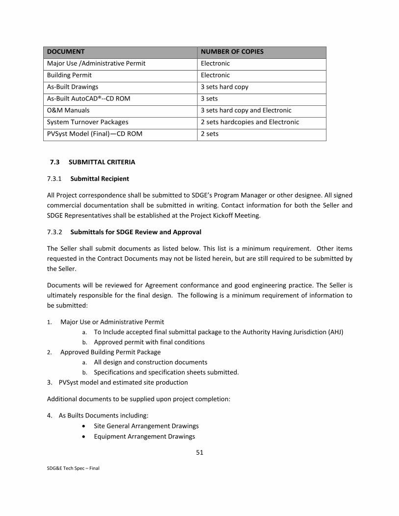
51
SDG&E Tech Spec – Final
DOCUMENT NUMBER OF COPIES
Major Use /Administrative Permit Electronic
Building Permit Electronic
As-Built Drawings 3 sets hard copy
As-Built AutoCAD®--CD ROM 3 sets
O&M Manuals 3 sets hard copy and Electronic
System Turnover Packages 2 sets hardcopies and Electronic
PVSyst Model (Final)—CD ROM 2 sets
7.3 SUBMITTAL CRITERIA
7.3.1 Submittal Recipient
All Project correspondence shall be submitted to SDGE’s Program Manager or other designee. All signed
commercial documentation shall be submitted in writing. Contact information for both the Seller and
SDGE Representatives shall be established at the Project Kickoff Meeting.
7.3.2 Submittals for SDGE Review and Approval
The Seller shall submit documents as listed below. This list is a minimum requirement. Other items
requested in the Contract Documents may not be listed herein, but are still required to be submitted by
the Seller.
Documents will be reviewed for Agreement conformance and good engineering practice. The Seller is
ultimately responsible for the final design. The following is a minimum requirement of information to
be submitted:
1. Major Use or Administrative Permit
a. To Include accepted final submittal package to the Authority Having Jurisdiction (AHJ)
b. Approved permit with final conditions
2. Approved Building Permit Package
a. All design and construction documents
b. Specifications and specification sheets submitted.
3. PVSyst model and estimated site production
Additional documents to be supplied upon project completion:
4. As Builts Documents including:
Site General Arrangement Drawings
Equipment Arrangement Drawings

52
SDG&E Tech Spec – Final
Foundation Drawings
Structural Design Drawings
Electrical One Line Diagrams
Electrical Three Line Diagrams
Wiring Diagrams
Electrical load flow and short circuit calculations
System Design and Control Criteria documents
Underground utilities (trench) drawings.
Shade Structure Plans, Elevations, and Typical Details
Communications diagrams
Data acquisition system input and output points list
Internet based HMI control screen graphics through PMRS
Catalog cut sheets and/or equipment technical specifications
Arc Flash analysis
Post Construction BMP design/plan with supporting analysis
Post-Construction BMP Maintenance Plan
Test and special inspection reports
5. Turnover Commissioning and Testing Documents
Construction turnover packages
Commissioning Procedures Manual
Commissioning test procedures
Commissioning test reports
Acceptance Test procedures
Acceptance Test reports
Operation and Maintenance Manual
7.4 O&M MANUAL
The Seller shall provide Operating and Maintenance (O&M) Manuals for all equipment supplied by the
Seller for the Project. In addition, the Seller shall provide an integrated full-System O&M schedule. . The
O&M Manuals shall meet the following criteria as a minimum:
1. O&M Manuals will include all literature, data sheets, etc. required for operation and
maintenance of the equipment. Nomenclature used to reference each item will be consistent
throughout O&M Manuals.
2. Data will be complete for all equipment and systems.

53
SDG&E Tech Spec – Final
3. Data will include drawings, diagrams (including wiring diagrams), pictures or actual photographs
when they add to the understanding and clarity of the text.
4. Precautions and warnings relative to the safety of life and equipment will be included where
applicable.
5. O&M Manuals shall be divided into the following sections:
Title
Index
Installation Instructions
Operation Instructions
Maintenance Instructions
Parts Catalog
Associated Publications
6. Installation instructions shall include the following:
Handling and rigging procedures
Equipment installation procedures, including assembly methods, special precautions,
sequence of work and adjustment requirements
Set points for all relays instruments meters and other devices requiring calibration
Complete set of the instrument installation details
Complete startup instructions, including a step-by-step startup checklist
7. Operation instructions shall include the following:
Starting instructions, detailed and specific, for all equipment furnished, with step-by-
step procedures to be followed and precautions and critical points noted and
emphasized as required.
Operating instructions, detailed and specific, for all equipment furnished including
precautions and critical points to be observed. A tabulation of possible operating
difficulties with the probable cause listed and remedial action recommended to be
taken shall also be included.
A Complete set of logic diagrams furnished with technical description
Shutdown instructions, detailed and specific, for all equipment furnished, noting the
step-by-step procedure to be followed for shutting down the equipment.
8. Maintenance instructions will include the following:
Lock-out and tag-out procedures
Disassembly instructions completely detailed and specific for major assemblies of all
equipment furnished, noting the step-by-step procedure to be followed. Precautions
and critical points to be observed will be noted and emphasized as required.
Maintenance instructions completely detailed and specific for major equipment
furnished, including preventive maintenance instructions. Schedules covering test and

54
SDG&E Tech Spec – Final
inspections to be performed after various periods of operation and a summary
description and identification of special tools required and furnished for maintenance
shall also be included.
Settings, clearance, and adjustment data tabulated for major equipment, covering
instrument settings for operation, alarm and shutdown, and operating clearances and
adjustments required for proper operation. Also, a tabulation of recommended
operation conditions for all equipment and systems. Whenever instrumentation is
provided with the manufacturer’s equipment, calibration procedures and instrument
data sheets for this instrumentation shall be provided.
Panel washing recommendations, including frequency based on site weather report,
time of the year, tools and equipment, crew size, duration, expected seasonal soiling
rates.
9. Parts Catalog will include the following:
Detailed replacement parts drawings and lists, including applicable specific replacement
part drawings and lists. These drawings and documents will include all information
required for ordering replacement parts, such as part name, part number, equipment
serial number, technical specifications, and quality assurance requirements.
Recommend spare parts for field instruments and IMC.
Special storage or handling procedures required by any particular parts shall be noted
including shelf life limits.
10. The Associated Publications section of the O&M Manuals shall be utilized when it is feasible to
include existing publications on sub-assembly or associated equipment components in the O&M
Manuals. Such publications shall be located in this section unless they can be subdivided, and
integrated as previously described.
7.5 QUALITY ASSURANCE MANUAL
The Seller’s QA/QC program shall be documented and submitted to SDGE. The content of the quality
assurance manual may be in the form of written descriptions of QA/QC policies, procedures, methods,
instructions, exhibits, or other quality assurance method descriptions.
Final QA/QC documentation records shall be turned over to SDGE at the completion of the Project. The
QA/QC records include all other documentation not turned over in the System Turnover Package.
END OF SECTION

55
SDG&E Tech Spec – Final
8 PERFORMANCE MODELING AND ANALYSIS REQUIREMENTS
8.1 INTRODUCTION
The Seller shall provide SDGE with a performance model for each PV Site using PVSyst modeling
software. The Seller shall use the newest version of PVSyst modeling software. This performance model
shall detail the hourly energy output in kWh AC (8760 hours for year 1) for each PV Site. When modeling
performance, the Seller shall use the inputs specified in this section and the appropriate values for the
equipment and systems as designed. All Seller assumptions shall be approved by SDGE prior to final
acceptance of the model (the final Owner approved model for a PV Site, the “Energy Model” for such PV
Site).
8.2 REQUIREMENTS
1. The Energy Model shall include post-inverter AC losses, including those losses occurring up to
the revenue meter located on the Site.
2. The Seller shall submit the following files to SDGE:
[PV SITE NAME].prj (with variant files or module model/block design specified)
If Seller proposes to use more than one module design, block design, or mounting design
to complete the System due to availability or other concerns, Seller shall:
o Provide a .prj file for each design permutation or a single .prj file with variant files
for each design permutation
o Provide a .pan file for each module design
o Provide a .ond file for each inverter design
o Weather data TMY3.cvs files used
3. The Seller shall provide the weather files provided to SDGE for System design and analysis. The
weather files represent a Typical Meteorological Year (TMY3) for the planned Site of the System.
The file shall consist of the TMY3 file for the Site and will be named TMY_solar.csv. The PV
System shall be assumed to be co-located with the meteorological site.
4. The Seller shall use the following input assumptions to PVSyst as provided. Where input
assumptions are not specified, the Seller shall provide their own input assumptions in a table
along with explanations and justifications. Explanations should be complete and address all
inputs necessary for simulation. SDGE shall approve all input assumptions.
The provided list was compiled based on the version of PVSyst available at the time this
specification was written. If there are additional inputs in the version of PVSyst available at the
beginning of the design phase, the Seller shall provide their input assumptions in a table to
capture these values.
a) Hidden Parameters and Preferences
Hidden Parameters – PVSyst Default Values

56
SDG&E Tech Spec – Final
Preferences – Default Values, Hay model
Please note changes in the input table when changes to hidden parameters are made to
avoid run errors etc. Hidden parameters and preferences can be found in the PVSyst
“preference” drop down menu.
b) Albedo – 0.2 throughout the year
c) Orientation – Choose Unlimited Sheds option
Plane Tilt – per Site design
Azimuth – per Site design
Number of Sheds – per Site design
Pitch – per Site design
Collector Band Width – per Site design
Top Inactive Band – per Site design
Bottom Inactive Band – per Site design
d) Horizon and Near Shadings – per Site design
e) System
Number of Inverters – per Site design
Initial Degradation – per module manufacturer
Modules in Series – per Site design
Number of Strings – per Site design
f) Detailed Losses
Thermal Parameters
o Constant Loss Factor Uc – 25.0 W/m^2K
o Wind Loss Factor Uv – 1.2 W/m^2K/m/s
o NOCT coefficient – fixed by Uc and Uv.
o NOCT Definition – open circuit (at Voc).
Ohmic Losses
o Wiring Resistance – Seller assumption, provide supporting specs to SDGE
o Voltage Drop Across Series Diode – Seller assumption
o AC Circuit (loss fraction at STC) – Seller assumption, provide supporting specs to
SDGE
o External Transformer (Iron/Iron) –Seller assumption, provide supporting specs to
SDGE
o External Transformer (Resistive/Inductive) – Seller assumption, provide supporting
specs to SDGE
Note: Losses are to be included up to the revenue meter, located on the Site.
Module Quality/Mismatch
o Module Quality – 0.8% Minimum. 0.5% for imperfect inverter maximum power
point tracking and 0.3% for one day per year of equivalent outage time. Increase
for additional losses and note.

57
SDG&E Tech Spec – Final
o Mismatch Losses – 0.5%
Soiling Losses
o January –2.2%
o February – 1.9%
o March – 1.7%
o April – 1.1%
o May – 2.6%
o June – 4.1%
o July – 5.8%
o August – 7.2%
o September – 8.0%
o October – 5.9%
o November – 4.2%
o December – 2.2%
IAM Losses – Bo = 0.05 unless surface is characterized by independent lab for
modules and report is provided.
g) Additional Losses – Seller may include additional loss factors not specifically detailed
above if approved by SDGE. Seller shall provide necessary back up data, specifications
and descriptions. Seller to describe where losses are input into energy estimate (done
post processing or included in model inputs).
5. The Seller shall provide PVSyst module files (.pan) to SDGE for each proposed module type.
The Seller shall provide PVSyst inverter files (.ond) to SDGE for each proposed inverter type.
6. The Seller shall provide analysis based on the parameters as listed below in PVSyst. The
Seller shall provide corresponding model files in .prj format (with variant files) for PVSyst.
The Seller shall provide to SDGE a performance prediction evaluation in hourly (8760 hours
for year 1) energy output in kWh of the PV System for each PVSyst run. This should include
post inverter AC losses.
a) At a minimum, the Energy Model must output a rated inverter capacity for at least one hour
of the first year, based on the TMY3 data set. This will be measured at inverter output.
b) As per the O&M Agreement terms, the System must also meet a first year energy
production measured at the System meter as specified in Section 9.
c) System Degradation rates used in calculating lifetime energy production shall not be greater
that 0.5% per year. Degradation should be assumed to be consistent over periods between
set warranty percentages.
d) Energy Model shall be designed to Minimum System Requirements as defined in Section
2.3.3.
7. All final Energy Models and associated files as described in this Section 8 shall be submitted
to SDGE prior to Acceptance Testing.
END OF SECTION

58
SDG&E Tech Spec – Final

59
SDG&E Tech Spec – Final
9 STARTUP AND COMMISSIONING
9.1 INTRODUCTION
The Seller shall have complete responsibility for calibration, testing, pre-operational checkout,
commissioning, start-up and testing of all equipment, including documentation, with the exception of
responsibilities specifically assigned to SDGE or others. The Seller shall submit copies of all
commissioning records to SDGE to document the results of all commissioning activities.
9.2 General START-UP AND COMMISSIONING SCOPE OF SERVICES
The Seller shall provide complete calibration, checkout, testing, and commissioning of all systems,
including performance of all manufacturers’ specific recommendations for commissioning, checkout or
testing in addition to those activities described in this Section. Additional specific testing requirements
included in this scope of work are provided in the SDG&E Electric Distribution System Interconnection
Handbook.
Commissioning shall occur in a sequence that will permit systematic checkout and trial operation of
each component before it is incorporated in the initial System operation. An operational acceptance test
followed by a functional acceptance test shall be completed for each system.
The Seller shall provide, at minimum, the following services as part of the required commissioning scope
of work:
9.2.1 General
1. Develop and maintain Commissioning Schedule
2. Prepare System Turnover Packages
3. Prepare required test records
4. Provide complete O&M Manuals for each equipment item provided
5. Conduct System performance, reliability, and functional tests
6. Perform site-specific training of SDGE’s operations staff
9.2.2 Mechanical
1. Check operation of all permanent Project equipment
2. Furnish start-up spares
3. Tag all equipment
9.2.3 Electrical
1. Check continuity of all cables
2. Megger all power cables 120 V and higher
3. Hi-pot medium voltage cable (2-15 kV)

60
SDG&E Tech Spec – Final
4. Dress out, fill and test transformers
5. Functional test all inverters, panels, and other System electrical equipment
6. Backfeed System in coordination with SDGE personnel
7. Functional test all control circuits
8. Test current transformers and potential transformers
9. Perform and calibrate final relay settings
9.2.4 Instrumentation
1. Verify instrumentation installation per instrument data sheets
2. Provide calibration set points
3. Complete final instrument calibration
4. Tag instruments with instrument identification numbers
5. Tag electrical panels, check breakers, etc.
6. Witness System controls Factory Acceptance Testing (FAT Testing)
7. Provide an integrated System Instrument Index
8. Check communication between System, SDGE communication base and the local Fire
Department (if required)
9.3 COORDINATION AND NOTIFICATION
9.3.1 Coordination
The overall Commissioning Schedule and structure shall be developed by the Seller's Commissioning
Manager so that each System Turnover Package is completed and presented to SDGE for review and
comment in proper sequence to support an orderly Commissioning.
The Seller shall maintain a system turnover checklist to track the status of System turnover packages.
Commissioning activities shall be coordinated with SDGE’s staff as necessary, and SDGE shall have the
right to witness any and all commissioning activities. The Seller shall be responsible for the first
energization and operation of the equipment.
The Commissioning Manager shall coordinate the efforts of the Seller’s personnel and applicable OEM
representatives. The Seller shall provide and connect the instrumentation required to monitor initial
operation and support control balancing, and shall record all data required to analyze the initial System
performance.
The Seller shall perform calibration of permanent instrumentation, coordinated by the Commissioning
Manager. Errors found during or after System commissioning shall be corrected. All subsystem Turnover
Package punch list items shall be completed and verified by the Commissioning Manager. Notification

61
SDG&E Tech Spec – Final
The Seller's Commissioning Manager shall notify SDGE a minimum of five (5) days in advance of all
scheduled construction alignments and testing of any piece of equipment or subsystem and shall
provide access for SDGE's representative to witness the testing. The Commissioning Manager is also
responsible for notifying and scheduling all applicable technical representatives and witnesses for
testing.
9.4 TURNOVER PACKAGES
9.4.1 Preparation
The Seller's Commissioning Manager shall prepare System and subsystem Turnover Packages. The
Commissioning sequence shall commence with scheduling and issuing packages for review and shall
continue with completion of construction and testing work for each package, electrical testing and
calibration, initial operation, and subsequent debugging of any operational problems by the Seller. The
Turnover Package shall be reviewed by SDGE, who shall notify the Seller upon acceptance of the
package.
The System Turnover Package shall contain the following:
1. Introduction
Brief Description of System
List of Interfaced equipment
2. Mechanical Completion Turnover Acceptance Form Sign-Off
Seller
Manufacturer's Service Representatives
Seller's Commissioning Manager
SDGE’s Engineer/Representative
Operations representative
3. Lists of Included Equipment
Major Equipment
Power Sources
Instrumentation/Electrical Devices
List of Alarms
List of Circuits
4. Applicable Drawings
Schematics
Network Diagrams
Manufacturer's drawings as required for functional checkout
Others as required
5. Remarks
Exceptions

62
SDG&E Tech Spec – Final
Special Conditions
Temporary Connections (jumpers, bypasses, etc.)
6. Supporting Documentation
Test Forms
Calibration Sheets
Manufacturer's Service Reports
Alignment Data Report
Others as required
The Turnover Package shall include one-line diagrams and electrical schematic diagrams marked to
define the limits of the subsystem. Applicable data and test forms and manufacturer's service reports
shall be prepared by the Seller's Commissioning Manager and included in the package. Manufacturer's
drawings shall be included as required to support the testing and functional checkout of the subsystem.
The Commissioning Manager shall note special instructions regarding additional construction activities
after Commissioning.
Sign-offs shall be provided by the Seller designating the completion of specific construction and testing
elements. Incomplete, noncritical elements shall be noted and described and an expected completion
date indicated.
9.4.2 Issuance
An introduction, a list of included equipment, engineering drawings showing subsystem boundaries and
content, and a list of applicable drawings for the Turnover Package shall be issued for information and
scheduling purposes as soon as they are prepared, but no less than fifteen (15) days prior to
commencement of Commissioning activities for a given system. The final Turnover Package shall be
submitted to SDGE only when it includes the completed and signed sign-off sheet, the completed test
sheets, exceptions sheets, manufacturer's service reports, and other applicable information.
9.4.3 Documentation
1. The Seller shall complete calibration and test forms for each device calibrated or tested. The
format of the forms shall be acceptable to SDGE. The forms shall include, but not be limited to,
the following information:
Equipment tag number
Equipment name
Equipment description and location
Description of test or check including date, time, and person performing test
Nameplate data
Readings taken

63
SDG&E Tech Spec – Final
Test results - description as required
Description of any corrective action
Description of test equipment including serial numbers
Observable data for future reference – notes
Test procedure used
Reference drawing numbers
2. The calibration and testing forms developed by the Seller shall include, but not be limited to, the
following:
Cable Test Data
Metering Test Data
Breaker Test Report
Ground Resistance Test Report
Power Cable Test Data
Ground Rod Resistance Test Report
Control Test Data
Calibration and Adjustment Report
3. All reports, calibration sheets, corrected drawings, and other data shall be maintained by the
Seller. The documents shall be maintained at the Seller 's field office until the specified turnover
to SDGE. The documents shall be made available for inspection and review upon request by
SDGE.
4. The manufacturer's service representative shall submit a service report to the Seller's
Commissioning Manager stating whether or not the equipment is ready for operation. Electrical
and control testing required by the manufacturer shall be performed under the service
representative's direction, and the results shall be attached to the service report. This Service
Report shall be placed in the turnover package prior to final submittal to SDGE.
5. As part of the System Turnover Package (STP) the Seller shall provide documentation supporting
the tasks completed per the OEM Operation Manual.
9.5 POST-COMMISSIONING CHECKOUT
9.5.1 System Checkout
Main systems shall be checked, operated, and tested by the Seller in the presence of and/or in
conjunction with SDGE after each individual piece of equipment and its accessories have been operated
and declared ready for on-line operation. The Seller's Commissioning Manager shall be present during
the main systems checkout.
All functional and operational testing of automatic controls, instrumentation, alarm systems, and all
other field testing of the main system shall be completed before the systems are started.
64
SDG&E Tech Spec – Final
9.5.2 On-Line Operational Checks
During on-line operation of the integrated systems, all equipment shall be checked by the Seller for
requirements recommended or required by the manufacturer of the specific piece of equipment.
Representatives of the Seller shall be present during the on-line operational checks.
The Seller shall be responsible for any recalibration and adjustments necessary to make the system
acceptable for on-line operation, and conducting System thermal imaging to identify any locations
where insulation is not properly installed or equipment is running hotter than normal.
9.6 ACCEPTANCE TESTING
The Seller is responsible for conducting the Acceptance Test of the complete Project, including PV modules, inverters, metering, controls, and accessories. The Seller shall provide all test equipment and special instrumentation required for the tests.
9.6.1 Definitions
Nameplate Rated Capacity: This shall mean the power output of the System in kilowatts (kW -
DC) based on the number of PV modules installed and the module nameplate rating at Standard
Test Conditions (STC). Aggregate Nameplate Capacity of installed modules shall be no
less than 100% of Project Nameplate Capacity.
Maximum System Losses: This shall be the electrical energy losses from and including the PV
modules through the System revenue meter, calculated as the difference between the
Nameplate Rated Capacity, corrected to actual ambient conditions; and the power output as
indicated at the revenue meter. Maximum System Losses include but are not limited to the
following losses: Ohmic, Soiling, Module Mismatch, Module Quality, Shading, Thermal,
Transformer, Inverter, etc.
Expected Energy Production: The annual electrical energy output in kilowatt-hours (kWH)
produced by the System as predicted by the approved Energy Model described in Section 8. This
shall mean the sum of 8,760 data points as generated by PVsyst using agreed upon inputs and
TMY3 weather data for the System Site, in MWh/MWAC/year. It shall include all auxiliary load
losses and system losses (up to the revenue meter).
Actual Energy Production: The electrical energy in kWH actually produced by the operational
Project during the course of the Energy Production Test, as measured by the system revenue
meter.
Energy Production Test: A 12 month test conducted pursuant to the O&M Agreement wherein
the Parties shall evaluate the Actual Energy Production in comparison with the Expected Energy
Production for such 12 month period. This evaluation is performed to demonstrate compliance

65
SDG&E Tech Spec – Final
with the Energy Production Guarantee for the particular Project as described in the O&M
Agreement.
Power Output Test: This shall mean the test performed on the System to measure the actual
power output at the revenue meter. This test shall be Successfully Run as a requirement for
Substantial Completion under the applicable EPC Contract to demonstrate to SDGE that the
installation is complete, that the Project satisfies the Performance Guarantee under the
applicable EPC Contract , and that all components are functioning correctly. Thereafter, this test
shall be performed on an annual basis under the O&M Agreement to determine compliance
with System degradation guarantees as detailed in the O&M Agreement.
Power Output Baseline: This shall mean the power output of the System at the time of
Substantial Completion of the Project under the EPC Contract (as demonstrated by the
Acceptance Test used to satisfy the conditions of Substantial Completion under such BTO
Contract). The results of such Power Output Test shall be corrected to DC-STC and used for
comparison with future Power Output Test results in order to measure and track System
degradation.
Performance Guarantee: A Project’s Performance Guarantee under its BTO agreement shall be
equal to ninety three percent (93%) (to account for system losses, ancillary load losses,
measurement uncertainty, and modeling uncertainty) of such Project’s nameplate power
capacity of the Project at unity power factor (as determine by the cumulative power rating of
the inverters installed in such Project), as measured at the Project’s revenue meter when
corrected to STC conditions.
Minimum System Performance Requirements: This shall mean the minimum Power Output and
Expected Energy Production values to be guaranteed by the Seller.
Primary Measurement Device: An instrument which provides a measurement or reading that is
used in calculating output power and annual energy production.
Secondary Measurement Device: An instrument which provides a measurement or reading that
is not used in calculating the output power or energy but is used as a check on primary
measurements.
Standard Test Conditions (STC): Standard Test Conditions are defined as the following:
o Irradiance in the plane of the array (module tilt angle and orientation) of 1,000 W/m2.
o 25°C module cell operating temperature as measured at the back surface or cell of the
module. (Reference module temperatures shall not be used for temperature
correction.)
o Air Mass (AM) of 1.5.
66
SDG&E Tech Spec – Final
Temperature Corrected Output (MWAC): The Temperature Corrected Output is the solution of
the linear regression equation for the Power Output Test, where x is equal to 1,000 W/m2.
Seller/SDGE Representatives: SDGE and the Seller shall define lead representatives for the
Power Output Testing. Lead test representative for the Seller shall be termed the Test Manager.
9.6.2 Power Output Test and Annual Test Overview
The following is an overview of the procedures to be utilized in connection with the execution of the
Power Output Test and, in accordance with the O&M Agreement, the annual tests of the complete
System, composed of an annual Power Output Test and the annual Energy Production Test. A detailed
Power Output Test procedure and an Energy Production Test procedure shall be developed by the Seller
and agreed upon by the parties as part of the Test Procedures as further defined in this document. This
approved Test Procedure shall be taken in conjunction with this section and shall be reviewed for
acceptance by SDGE prior to testing.
The tests are to be executed in sequence as follows:
Once the Seller has successfully completed all start-up and commissioning activities, including
trial operation of all equipment, the Seller shall commence the Power Output Test and
demonstrate that the System satisfies the Performance Guarantee and all components are
complete and fully functional. The Seller shall remediate the shortcomings and re-test until the
Project achieves the Performance Guarantee. Seller must achieve the Performance Guarantee
to meet Substantial Completion.
Upon acceptance by SDGE of the Power Output Test, the test results will be used to establish
the Power Output Baseline. This baseline will establish the power output capacity of the new
System for comparison with future Power Output Tests.
Following the successful completion of the Power Output Test, and provided that the other
requirements for Substantial Completion have been satisfied, the Project will be granted
Substantial Completion, and commercial energy production will commence. As part of the
O&M Agreement, at the end of one year of energy production, the Seller shall perform the
annual Energy Production Test and demonstrate that the System Actual Energy Production
meets the requirements of the Energy Production Guarantee as described in Section 9.6 and
listed in Attachment 1, Minimum System Performance Requirements.
As part of the O&M Agreement, and at the time specified in the O&M Agreement, and annually
thereafter for the term of the O&M Agreement, the Seller shall repeat the performance of the
Power Output Test, using the Performance Monitoring System (at 15 minute data acquisition
intervals). The results of each annual test will be corrected to STC and compared with the Power

67
SDG&E Tech Spec – Final
Output Baseline. This comparison will establish the amount of annual degradation experienced
by the PV Modules (Panels). The System wide t degradation shall not exceed 0.5% per year.
9.6.3 Energy Production Guarantee
Seller guarantees that the Actual Energy Production of each Project shall equal or exceed ninety percent
(90%) of the Expected Energy Production, including all system losses and auxiliary load deductions, and
accounting for module degradation (the “Energy Production Guarantee”).
9.6.4 Pre-Test Activities
Prior to the start of a Power Output Test, the Seller shall complete the following:
Test Plan: Thirty (30) days prior to commencement of a Power Output Test, the Seller shall
submit to SDGE for review and approval a formal Power Output Test Procedure which shall
detail all Power Output Test activities including:
1. Uncertainty analysis.
2. Specification “cut-sheets” for all Primary Measurement Devices. Also provide location of
these measurements for field verification.
3. Field testing procedures (to meet minimum test duration and frequency requirement as
specified in Table).
4. List of Secondary Measurement Devices and locations.
5. Applicable Equipment factory test certificates.
6. Inverter factory test certificates.
7. Calculations, methodologies, equations and procedures.
Pre-Test Meeting: Prior to each test, a pre-test meeting shall be conducted and recorded. The
meeting shall review the applicable approved Power Output Test Procedure, instrumentation
locations, calibration sheets and other relevant topics including safety requirements. Minutes of
this meeting shall be recorded by the Seller and approved by both parties.
Pre-Test Runs: The Seller must, at its discretion (and cost), perform preliminary test runs prior
to the official test in order to validate instrument readings, data acquisition operation and stable
system operation. SDGE shall be notified of preliminary test runs and shall be allowed to
observe testing.
Power Output Test Scheduling: The Seller shall notify SDGE in writing of proposed test date not
less than fifteen (15) days prior to the proposed date for a Power Output Test.
Power Output Pre-test Conditions: Tests may be performed only when the following conditions
are met:

68
SDG&E Tech Spec – Final
1. All functional tests for such have been successfully completed, and System is in
automatic operation.
2. Weather conditions are as required to complete the Power Output Test, as addressed in
this exhibit and in the approved Test Procedures.
3. Utility grid voltage is stable and within +/- 5% of design voltage.
4. There is grid connectivity at each inverter such that the Power Output Test can be
accomplished under load.
9.6.5 Power Output Test
The objective of the Power Output Test is for the Seller to demonstrate to SDGE that (a) with respect to
the Power Output Test run as part of the BTO Contract, that the System satisfies the Performance
Guarantee under the BTO Contract; and (b) with respect to a Power Output Test run as part of the O&M
Agreement, that degradation is within the guaranteed limits as defined in the O&M Agreement, when
the results are corrected from the test conditions to STC. The following is the outline of required steps
for completion of the Power Output Test:
1. Conduct field tests: Measure and record AC power output (Pm) at the Combining Switchgear,
module temperature(s) from representative modules in the solar field, and irradiance levels
using laboratory certified reference modules identical to those mounted in the field. Record this
data over a duration and frequency to achieve a sufficient data population and minimize
random error.
a) The power output monitoring through the power meter installed by Seller at the
Combining Switchgear shall act as the primary measurement.
b) Module temperature shall be measured by use of Resistance Temperature Detectors
(RTD) attached to the back side of representative modules in the solar field, or
embedded into the module cells. A minimum of 8 modules will be instrumented for
temperature readings. These shall be distributed throughout the field with at least four
on the perimeter rows of the solar arrays.
c) Laboratory certified reference modules shall be:
o Calibrated by National Renewable Energy Laboratory or approved equal with
appropriate supporting documentation.
o Of the same type (identical optical and electrical properties) and rated power as
those in the solar field. (The Contractor shall submit flash test results of
reference modules. Reference module power rating shall be equal to the rated
power of the solar array modules to within +/- 1%.)
o Mounted in the same plane (same tilt angle and orientation) and elevation as
field solar arrays.

69
SDG&E Tech Spec – Final
o Labeled with permanent weatherproof label as certified calibrated reference
module.
o Provided in quantities as specified in Section 9.6.
2. Compile and reduce test data set: For each Power Output Test, raw test data shall be analyzed
and reduced to eliminate data points that clearly exhibit a high degree of random error, such as
shading, disturbances or unstable weather that were not indicative of the test. The Contractor
shall document all data that are eliminated and review with SDGE for acceptance. Details shall
be included in the agreed upon Test Procedures for the Power Output Tests.
3. Apply temperature correction factors: Correct each power measurement to 25C (STC
temperature) using the module temperature coefficient of power to yield the corrected output
power, PSTC. To ensure a mean representative solar module temperature is used in this
correction calculation, the module temperature transmitters shall be placed as described above
in section 2 under Conduct field tests and in quantities as specified in Section 9.6.6.
4. Ancillary Load Considerations: The test shall account for ancillary loads up to the revenue meter
which deduct energy from the net AC output. These are loads which are used for the running of
the System but which reduce the net delivered power of the System. An example of this would
be HVAC/lighting loads for the buildings (if used) which house the inverters, back feed power to
transformers, tracking motors (if used), etc. If such loads exist, they must be run during the test.
This shall be done by one of two ways:
a) If the loads are connected to the System and not to a separate circuit, then the loads
shall be forced to run during the test.
b) If the loads are connected to a separate circuit, independent from the solar field, then
an agreed upon amount shall be deducted from the resultant tested AC output.
5. Plot data set using computational software: Plot temperature-corrected power measurement
versus measured solar irradiance as a scatter graph (y axis = power, x axis = plane of array
irradiance).
6. Generate curve fit: Using computational software, generate a linear regression curve fit through
the data and obtain the curve equation.
7. Solve for standard insolation, 1000 W/m2: Solve the equation using a value of 1000 watts/m2
for the irradiance to calculate what the value would be at STC.
8. Determine pass / fail: Compare the temperature corrected output resulting from the Power
Output Test to (a) with respect to the EPC Contract, the Performance Guarantee; and (b) with
respect to the O&M Agreement, the Power Output Baseline. With respect to the BTO Contract,
failure to achieve the Performance Guarantee shall mean that Seller cannot achieve Substantial

70
SDG&E Tech Spec – Final
Completion until remedial actions are undertaken to cause the System to achieve the
Performance Guarantee. With respect to the O&M Agreement, the difference between actual
output and the Power Output Baseline shall determine the annual System degradation. The
amount of degradation shall be evaluated in accordance with the guaranteed limits as
established in the O&M Agreement.
9.6.6 Test Measurements
All test measurement devices used shall be fully documented in terms of their make/model, accuracy,
calibration and location. The following tables summarize these measurements:
Power Output Test Measurements (Minimum)
Measurement Quantity Type Instrument Type Range Minimum Accuracy
Solar Irradiance
2 Primary NREL or approved test laboratory calibrated module
+/- 5.0%
1 Secondary (at Site Met Stations)
Pyranometer 400-1100nm
+/- 3.0%
Power (kW), PF (power factor), Current (amperes), Voltage
1 Primary
Permanent ANSI C-12 power meters installed by Seller at the main circuit breaker switch with calibrated CTs and PTs.
+/- 0.2%
Net Power Output 1 Secondary (at revenue meter)
Power Metering +/- 0.2%
Module cell temperature
8 per Block, 16
total Primary
Platinum RTD (resistance temperature detector) transmitter (.00385 TCR DIN B) or Thermistor, on back surface or cell of module
-10 to 120 °C
+/- 0.3 °C
AC/DC power, volts and amperage
1 per Inverter
Secondary From inverter via SCADA N/A +/- 1/0%
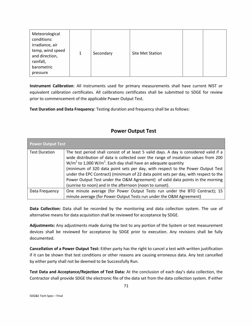
71
SDG&E Tech Spec – Final
Meteorological conditions: irradiance, air temp, wind speed and direction, rainfall, barometric pressure
1 Secondary Site Met Station
Instrument Calibration: All instruments used for primary measurements shall have current NIST or
equivalent calibration certificates. All calibrations certificates shall be submitted to SDGE for review
prior to commencement of the applicable Power Output Test.
Test Duration and Data Frequency: Testing duration and frequency shall be as follows:
Power Output Test
Power Output Test
Test Duration The test period shall consist of at least 5 valid days. A day is considered valid if a wide distribution of data is collected over the range of insolation values from 200 W/m2 to 1,000 W/m2. Each day shall have an adequate quantity (minimum of 320 data point sets per day, with respect to the Power Output Test under the EPC Contract) (minimum of 22 data point sets per day, with respect to the Power Output Test under the O&M Agreement) of valid data points in the morning (sunrise to noon) and in the afternoon (noon to sunset).
Data Frequency One minute average (for Power Output Tests run under the BTO Contract); 15 minute average (for Power Output Tests run under the O&M Agreement)
Data Collection: Data shall be recorded by the monitoring and data collection system. The use of
alternative means for data acquisition shall be reviewed for acceptance by SDGE.
Adjustments: Any adjustments made during the test to any portion of the System or test measurement
devices shall be reviewed for acceptance by SDGE prior to execution. Any revisions shall be fully
documented.
Cancellation of a Power Output Test: Either party has the right to cancel a test with written justification
if it can be shown that test conditions or other reasons are causing erroneous data. Any test cancelled
by either party shall not be deemed to be Successfully Run.
Test Data and Acceptance/Rejection of Test Data: At the conclusion of each day’s data collection, the
Contractor shall provide SDGE the electronic file of the data set from the data collection system. If either
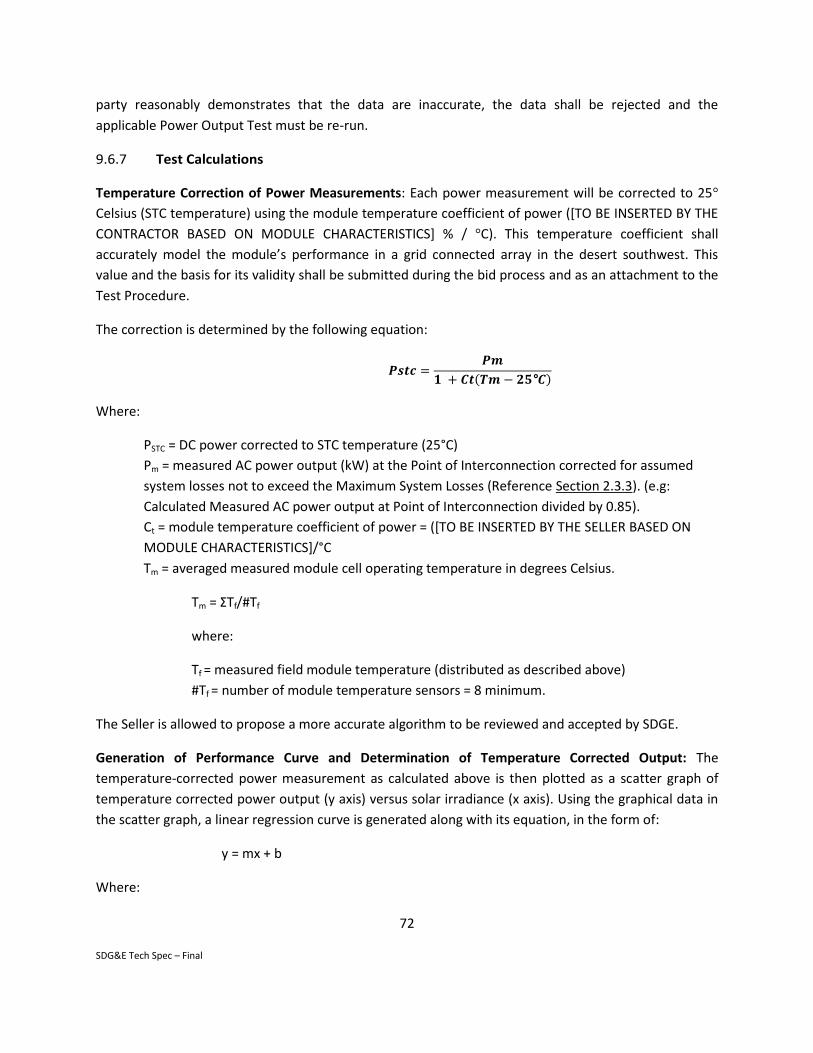
72
SDG&E Tech Spec – Final
party reasonably demonstrates that the data are inaccurate, the data shall be rejected and the
applicable Power Output Test must be re-run.
9.6.7 Test Calculations
Temperature Correction of Power Measurements: Each power measurement will be corrected to 25°
Celsius (STC temperature) using the module temperature coefficient of power ([TO BE INSERTED BY THE
CONTRACTOR BASED ON MODULE CHARACTERISTICS] % / °C). This temperature coefficient shall
accurately model the module’s performance in a grid connected array in the desert southwest. This
value and the basis for its validity shall be submitted during the bid process and as an attachment to the
Test Procedure.
The correction is determined by the following equation:
𝑷𝒔𝒕𝒄 =𝑷𝒎
𝟏 + 𝑪𝒕(𝑻𝒎 − 𝟐𝟓°𝑪)
Where:
PSTC = DC power corrected to STC temperature (25°C)
Pm = measured AC power output (kW) at the Point of Interconnection corrected for assumed
system losses not to exceed the Maximum System Losses (Reference Section 2.3.3). (e.g:
Calculated Measured AC power output at Point of Interconnection divided by 0.85).
Ct = module temperature coefficient of power = ([TO BE INSERTED BY THE SELLER BASED ON
MODULE CHARACTERISTICS]/°C
Tm = averaged measured module cell operating temperature in degrees Celsius.
Tm = ΣTf/#Tf
where:
Tf = measured field module temperature (distributed as described above)
#Tf = number of module temperature sensors = 8 minimum.
The Seller is allowed to propose a more accurate algorithm to be reviewed and accepted by SDGE.
Generation of Performance Curve and Determination of Temperature Corrected Output: The
temperature-corrected power measurement as calculated above is then plotted as a scatter graph of
temperature corrected power output (y axis) versus solar irradiance (x axis). Using the graphical data in
the scatter graph, a linear regression curve is generated along with its equation, in the form of:
y = mx + b
Where:

73
SDG&E Tech Spec – Final
y = power (corrected)
m = slope
x = irradiance (W/m2)
b = y intercept
The resulting equation is solved for Irradiance of 1000 W/m2 to calculate the Temperature Corrected
Output (MW).
The Coefficient of Determination (R-squared) shall be 0.96 or higher (for the complete data set of the
test) to validate a statistically acceptable fit.
Combine the the Temperature Corrected Output results for each day to determine final results: The
data shall be plotted together to determine the final Power Output Test result. Each day’s results,
however, must first be reviewed and approved by SDGE. If one day, for example, is unacceptable, then
an additional test day shall be required if still below the five day minimum. The minimum R2 value for
each day is 0.92. The minimum R2 value for the overall test (5 day minimum) is 0.96.
9.6.8 Test Reporting
The Seller shall submit a detailed test report within five (5) business days of completion of successful
Power Output Test to SDGE, after which SDGE will have five business days to review and either accept or
reject. The test report shall consist of the following at a minimum:
Test Procedures (as executed)
Instrument calibration sheets/certificates
Test data (manual and data acquisition)
Field notes
Calculations and results
Conclusions
9.6.9 Power Output Degradation Monitoring
After Substantial Completion, Seller will monitor the DC system health through use of power
measurements at the inverter input or at the smart combiner boxes (if used). Seller will identify
questionable module strings to SDG&E. The Seller will be responsible for testing and remediating any
modules that have dropped below their warranted power output or module strings that are otherwise
underperforming. The Seller’s contractual responsibilities regarding power output degradation will end
once the O&M Agreement is terminated. At this point, to the extent it has not already occurred, the
module warranty and its enforcement shall be transferred to SDGE.

74
SDG&E Tech Spec – Final
9.6.10 Energy Production Test
The annual System performance shall be evaluated by conducting an Energy Production Test under the
O&M Agreement. The objective is to ensure that the Actual Energy Production of the System meets the
Energy Production Guarantee. This Test shall be performed each year of the O&M Agreement.
The annual Energy Production Test shall be performed as follows:
1. Annually during the term of the O&M Agreement, beginning one year after the Substantial
Completion Date of the applicable Project under the BTO, accounting for any down time and in
accordance with the approved test procedures, the Seller, along with SDGE as a witness, shall
read and record the Actual Energy Production for that year from the permanent power revenue
meter. This shall be done each year that an Energy Production Test is run.
2. As a secondary measurement to check this amount, the Seller and SDGE shall sum the data from
the monitoring system up to the time stamp that correlates to the visual meter reading.
3. The primary and secondary amounts shall be documented in a report and submitted to SDGE for
approval.
4. If the measured annual Actual Energy Production for that year meets the Expected Energy
Production as determined by the applicable Energy Model, then the Seller shall have met the
Energy Production Guarantee for such Project.
5. If the measured Actual Energy Production is less than the Expected Energy Production value,
then the Seller shall have failed to meet the Energy Production Guarantee for such Project. The
Seller shall compensate SDGE for the Performance Liquidated Damages as set forth in the O&M
Agreement .
6. If interruptions in energy production, outages, or recalibration of instrumentation occur, these
events shall be recorded and reported so that the data can be evaluated accordingly. However,
in no case shall these events excuse the Seller for having not met the applicable annual Energy
Production Guarantee, unless there was an unplanned outage caused by SDGE or a Force
Majeure event. In such case, the time that was missed will be made up so that a total of 365
valid days of testing is logged.
7. If there is a significant difference (more than ± 7.5%) between the measured Actual Energy
Production and the Expected Energy Production (as determined by the Model), the cause of this
difference shall be investigated and reported to SDGE.

75
SDG&E Tech Spec – Final
9.6.11 Annual Energy Production Test Procedures
Prior to the commencement of an annual Energy Production Test, the following conditions shall be met:
1. Thirty (30) days prior to the commencement of the annual Energy Production Test, Seller shall
submit to SDGE:
Documentation of scheduled outages and their impact on the total number of valid test
days
2. Seller shall submit to SDGE:
Historical energy production of System to date including monthly average profiles.
Applicable measurement equipment calibration test certificates and records.
A comparison of the previous year’s weather data to TMY3 data.
3. During the term of the O&M Agreement, Seller shall be allowed to monitor the measurements
and maintenance of the System. Access to the site will be granted to the Seller’s authorized
individuals only.
4. At least two (2) weeks prior to the first day of each annual test, a meeting shall be held between
the Seller and SDGE. The meeting shall schedule the Test dates; introduce the lead
representatives, review the above preliminary report and applicable approved procedures,
instrumentation locations, calibration sheets and other relevant topics including safety
requirements. Minutes of this meeting shall be recorded by the Seller and approved by both
parties.
As part of the test procedure, all test measurement devices shall be fully documented in terms of their
make/model, accuracy, calibration and location. Table 9.6.12 summarizes these measurements:
Table 9.6.12 Annual Energy Production Test Measurements (Minimum)
Measurement Qty Type Instrument Type Minimum Accuracy
Energy (kWh),
Power (kW)
1 Primary Permanent ANSI C-12 power meter
installed at the main circuit breaker
switch.
+/- 0.2%
Energy (kWh) 1 Secondary From Monitoring System – direct
accumulated measurements from
revenue meter, and from inverter.
+/- 0.5%
Meteorological conditions:
solar irradiation, air temp,
1 Primary Onsite weather station

76
SDG&E Tech Spec – Final
wind speed and direction 1 Secondary Secondary weather station or
Substation weather station (If
available) or data from closest
airport.
All instruments used for primary measurements shall have current NIST or equivalent calibration
certificates. All calibrations certificates shall be submitted to SDGE for review prior to turn over of the
System and commencement of the applicable annual Energy Production Tests.
Any adjustments made prior to the Energy Production Test to any portion of the System or test
measurement devices shall be submitted by SDGE to Contractor for review prior to commencement of
the Energy Production Test.
The Energy Production Test results will be observed by, analyzed and approved by SDGE. Failure of any
section will require the appropriate remedy with re-testing/reporting at no additional cost to SDGE.
END OF SECTION

77
SDG&E Tech Spec – Final
Attachment 1: Minimum System Performance Requirements
Actual first year Capacity and Energy Guarantees are shown below.
Property Name Nameplate
Rated Capacity
(kWDC STC)
Minimum System
Power Output
(kWDC STC)1
Expected Energy
Production in Year
One (kWhAC/yr)
Minimum Actual
Energy Production in
Year One (kWhAC/yr)2
1.Minimum System Power Output (kWDC-STC) shall be no less than 93.0% of Nameplate Rated Capacity
.2Minimum Actual Energy Production in Year One shall be no less than 90.0 % of Expected Energy Production in Year One
Power Output and Energy Production Guarantees
The Power Output and Energy Production Guarantees are described in Section 9.6

78
SDG&E Tech Spec – Final
Attachment 2: Site Conditions
The equipment specified herein will be installed outdoors at Sites located in San Diego County,
California. The design data for these Sites is as follows:
Dry bulb record minimum temperature: 25°F
Dry bulb record maximum temperature: 111°F
Maximum wet bulb temperature: 69°F (concurrent with maximum dry bulb temperature)
Annual average relative humidity: 70%
Maximum Relative Humidity: 100%
Annual average precipitation: 10.65 inches
Elevation: 200 feet above MSL
Design wind speed: 85 Mph
Greatest 24-hour precipitation: 3.23 inches
In addition to the above general data, specific hourly climate data will be provided in a TMY3 file for PV
System design purposes.

79
SDG&E Tech Spec – Final
Attachment 3: Approved Equipment Manufacturer List
Seller has proposed the following equipment in the Bid:
PV Module:
Inverters:
Racking Systems:
Performance Monitoring System:
Substitute equipment shall comply with the following lists, but only with SDG&E approval of the specific
equipment.
The following Approved Equipment Manufacturer List provides the names of manufacturers that have been pre-approved by SDGE as potential equipment providers for the PV Systems. Seller may propose using equipment from alternative manufacturers not listed in the Approved Equipment Manufacturer List provided that the equipment complies fully with the complete requirements of this Technical Specification and Agreement. Seller must clearly define their request to deviate from this Approved Equipment Manufacturer List in the Proposal and SDGE reserves the right to reject such request. PV Module:
• Canadian Solar • Suntech Power • Yingli Green Energy • Trina Solar • SunPower • Sharp • Siliken • First Solar • Hyundai Heavy Industries • Solon
• Kyocera Solar • Sanyo Electric • Samsung Electronics • REC Solar • SolarWorld • Jinko Solar • LG Electronics • LDK Solar • Mitsubishi Electric • Hanwha
Inverters:
• SMA America
Monitoring and Data Collection Systems:
• To be specified by SDG&E
Pad Mount Distribution Transformers: • Howard ABB • Central Moloney Cooper

Revision 4/15/2015 SDGE
Attachment 4: Photovoltaic Module Requirements
1.0 SCOPE
This section outlines the minimum design and functional requirements of the PV Modules that will be
integrated into a complete Photovoltaic system referenced in the SDGE Technical Specification.
1. The PV Module will be comprised of all material and components required for a fully functional
PV Module and shall conform in all respects to the requirements of this Technical
Specification.
2. model crystalline silicon or equivalent modules shall be used. Alternative panels are subject to
approval by SDG&E. The PV Module will meet all applicable US and international
specifications in effect at the time of this Specification. All Codes and Standards to which the
PV Module complies will be listed on the Module Data Sheets.
3. The PV Modules may be manufactured in the United States (preferred) or other approved
locations as outlined in the commercial sections of the Agreement.
4. The PV Module Data Sheets shall contain a warranty of power output, expressed in net
Watts (DC). The Manufacturer shall specify and guarantee the long term output for the first
ten (10) years and twenty-five (25) years. Power Output Degradation shall be specified for
each year, to 25 years.
5. The PV Module shall be designed for ease of installation with the minimum number of cabling
interfaces in order to maximize the overall electrical efficiency of the final array configuration
into which the PV Module is incorporated.
6. The Manufacturer shall provide a recommended procedure for disposal of the Modules at the
end of their useful life. The Manufacturer shall also provide recommended procedures for
disposal of broken or irreparable Modules.
2.0 GENERAL REQUIREMENTS
2.1 Codes and Standards
The PV Modules shall fully comply with all applicable Standards, including, but not limited to:
UL 1703, Flat-Plate Photovoltaic Modules and Panels
IEC 61730, Photovoltaic Module Safety Qualification

81
SDG&E Tech Spec Revision: 14-Apr-15
IEC 61215, Crystalline silicon photovoltaic modules or IEC 61646, Thin-film
photovoltaic modules
ASTM E 1171
California Energy Commission (CEC) Senate Bill 1
(http://www.gosolarcalifornia.org/equipment/pv_modules.php)
NFPA compliant
2.2 Design Requirements
1. The PV Modules will have a minimum nominal rating of 70 Watts at least a nominal voltage of
600 Volts.
2. The PV Modules will be designed to operate under a range of environmental conditions,
including marine, desert, alpine, and industrial environments, as defined in Attachment 2 of
the Technical Specifications.
3. Each Module’s actual power should be within a minimum tolerance of 5% of the
Manufacturer’s specified module rated power. The lower bound of the panel power
tolerance will be used to calculate the DC rating of the plant.
4. Each Module will have a minimum five year guarantee for design and workmanship.
5. The Modules shall be certified by a nationally or internationally recognized certifying agency
such as the California Energy Commission.
6. Each string of modules should be assembled and batched by Impp to minimize the mismatch
losses.
2.3 Performance Requirements
The PV Modules shall conform at a minimum to the following general characteristics at the
nominal manufacturer rating at standard test conditions (STC) (DC watts) with corresponding data
at estimate PTC (watts) noted below.
The following information shall be provided by the PV Module Manufacturer at STC
Power
Voltage at PMAX - VMPP(V)
Current at PMAX - IMPP(A)
Open Circuit Voltage – VOC(V)
Short Circuit current – ISC (A)
Maximum System Voltage – VSYS(Vdc)
Temp Coefficient of PMPP – TK (%/ °C)
Temp Coefficient of VOC, high temp (>25°C) – TK (%/ °C)
Temp Coefficient of VOC, low temp (-40°C to +25°C) – TK (%/ °C)

82
SDG&E Tech Spec Revision: 14-Apr-15
Temp Coefficient of ISC – TK (%/ °C )
Limiting Reverse Current – IR(A)
Maximum Source Circuit Fuse – ICF(A)
For the proposed Module and ratings at 1000 W/m2, air mass at 1.5g and cell temp at 20°C, the Bidder
shall provide the following:
Nominal Power (+/-5%) – PMPP(W)
Voltage at PMAX – VMPP(V)
Current at PMAX – IMPP(A)
Open Circuit Voltage - VOC(V)
Short Circuit Current - ISC(A)
IV Curve for Bidder’s proposed Module showing current/voltage
characteristics with dependence on irradiance and Module temperature at
1000 W/m2 , at 800 W/m2, and at 400 W/m2
3.0 LONG-TERM DEGRADATION WARRANTY. The Long-Term Degradation Warranty to be provided by the Panel Manufacturer shall meet (as a minimum) the following criteria (i .e. Sections 3.1 through 3.4).
3.1 MATERIALS WARRANTY (YEARS)
The Modules shall have a minimum ten year guarantee of materials, design and workmanship.
The Manufacturer shall provide information on the service levels and intervals to be maintained to
sustain the warranty.
3.2 POWER WARRANTY (YEARS)
Manufacturer shall provide modules with a maximum degradation of 10% over ten years and 20% over
twenty-five years.
3.3 DESIGN LIFE WARRANTY (YEARS)
The PV Modules will have a design life of at least twenty-five years from the date of installation, and
no less than twenty seven years from the date of manufacture.
3.4 REPLACEMENT PROCEDURE.
The Long-Term Degradation Warranty shall clearly state the process by which Owner shall
make a claim against the warranties described above, including a name, contact address, fax

83
SDG&E Tech Spec Revision: 14-Apr-15
number, and phone number. The facility to which any panels must be shipped for replacement
shall be located in the continental United States. The Long-Term Degradation Warranty will
also contain clear time lines for responses to warranty claims, including negative responses.
The Long-Term Degradation Warranty shall provide an objective test in determining how panel
output will be determined in case of disputes.

84
SDG&E Tech Spec Revision: 14-Apr-15
Attachment 7: Equipment Warranties
1.0 Inverters: The inverters are covered by a twenty (20) year manufacturer’s limited warranty.
2.0 Racking System: The Racking system is covered by a twenty (20) year manufacturer’s limited warranty.
3.0 Monitoring System: The monitoring system is covered by a twenty (20) year manufacturer’s limited warranty.
The Long-Term Degradation Warranty does not apply to:
1.Components of the Grid-Tied PV system that have been subject to misuse, neglect, accident, abuse, vandalism, alteration, force majeure event or serviced/repaired by anyone other than, for the duration of the Operation and Maintenance Agreement with . After expiration of the O&M Agreement, the manufacturer’s Long Term Degradation Warranty shall remain in effect. 2.Items that require replacement due to normal wear and tear, normal erosion or corrosion or casualty loss (other than as a result of any failure of the Defect Warranty or the Long-Term Degradation Warranty)