Technical Specifications (In-Cash Procurement) The …static.iter.org/codac/pcdh7/Folder...
16
PDF generated on 04-Jun-2013 DISCLAIMER : UNCONTROLLED WHEN PRINTED – PLEASE CHECK THE STATUS OF THE DOCUMENT IN IDM Technical Specifications (In-Cash Procurement) The CODAC - Plant System Interface This document describes the software interface between CODAC and the plant system I&C and specifies how this interface must be implemented in the plant system I&C. Approval Process Name Action Affiliation Author Di Maio F. 16-May-2013:signed IO/DG/DIP/CHD/CSD/CDC Co-Authors Reviewers Journeaux J.- Y. Park M. Yonekawa I. 16-May-2013:recommended 28-May-2013:recommended 17-May-2013:recommended IO/DG/DIP/CHD/CSD/PCI IO/DG/DIP/CHD/CSD/CDC IO/DG/DIP/CHD/CSD/PCI Approver Wallander A. 04-Jun-2013:approved IO/DG/DIP/CHD/CSD Document Security: level 1 (IO unclassified) RO: Di Maio Franck Read Access AD: ITER, AD: External Collaborators, AD: Division - Control System Division - EXT, AD: Section - CODAC - EXT, AD: Section - CODAC, AD: Auditors, project administrator, RO, AD: Division - Control System Division IDM UID 34V362 VERSION CREATED ON / VERSION / STATUS 30 Apr 2013 / 2.1 / Approved EXTERNAL REFERENCE
-
Upload
dinhnguyet -
Category
Documents
-
view
217 -
download
0
Transcript of Technical Specifications (In-Cash Procurement) The …static.iter.org/codac/pcdh7/Folder...

PDF generated on 04-Jun-2013DISCLAIMER : UNCONTROLLED WHEN PRINTED – PLEASE CHECK THE STATUS OF THE DOCUMENT IN IDM
Technical Specifications (In-Cash Procurement) The CODAC - Plant System Interface
This document describes the software interface between CODAC and the plant system I&C and specifies how this interface must be implemented in the plant system I&C.
Approval Process Name Action AffiliationAuthor Di Maio F. 16-May-2013:signed IO/DG/DIP/CHD/CSD/CDCCo-AuthorsReviewers Journeaux J.- Y.
Park M. Yonekawa I.
16-May-2013:recommended28-May-2013:recommended17-May-2013:recommended
IO/DG/DIP/CHD/CSD/PCIIO/DG/DIP/CHD/CSD/CDCIO/DG/DIP/CHD/CSD/PCI
Approver Wallander A. 04-Jun-2013:approved IO/DG/DIP/CHD/CSDDocument Security: level 1 (IO unclassified)
RO: Di Maio FranckRead Access AD: ITER, AD: External Collaborators, AD: Division - Control System Division - EXT, AD: Section -
CODAC - EXT, AD: Section - CODAC, AD: Auditors, project administrator, RO, AD: Division - Control System Division
IDM UID
34V362VERSION CREATED ON / VERSION / STATUS
30 Apr 2013 / 2.1 / Approved
EXTERNAL REFERENCE
PDF generated on 04-Jun-2013DISCLAIMER : UNCONTROLLED WHEN PRINTED – PLEASE CHECK THE STATUS OF THE DOCUMENT IN IDM
Change LogTitle (Uid) Versio
nLatest Status Issue Date Description of Change
The CODAC - Plant System Interface (34V362_v2_1)
v2.1 Approved 30 Apr 2013
Updated for PCDH 7 + extensions from CODAC Core System v4- COS/PSOS completed- Addition on alarms and acrive interfaces (NJU)- System monitoring completed- Addition of SDN data- Simulation mode completed- Interface sheet chapter added
The CODAC - Plant System Interface (34V362_v2_0)
v2.0 Approved 10 Feb 2011
Version for PCDH 6.Updated with the outcome of the review: correction of the COS table, addition of read commands, mention of log servers.
The CODAC - Plant System Interface (34V362_v1_4)
v1.4 Signed 10 Jan 2011
Reuse OPSTATE and OPREQ as variable names, as in prvious version.Final change before review.
The CODAC - Plant System Interface (34V362_v1_3)
v1.3 Signed 07 Jan 2011
Version for review.
The CODAC - Plant System Interface (34V362_v1_2)
v1.2 Approved 28 Jan 2010
After I&C IPT review.Chapter 2 stabilized.
The CODAC - Plant System Interface (34V362_v1_1)
v1.1 Signed 10 Dec 2009
New drfat after internal review. Still many open points.
The CODAC - Plant System Interface (34V362_v1_0)
v1.0 In Work 10 Dec 2009

Page 1/14
Table of contents1 INTRODUCTION...............................................................................................................................2
1.1 PCDH context..................................................................................................................................21.2 Scope of the document ....................................................................................................................21.3 References ........................................................................................................................................31.4 Acronyms .........................................................................................................................................3
2 PLANT SYSTEM I&C CONFIGURATION ...................................................................................4
2.1 Plant system I&C function identifier ............................................................................................42.2 Plant system I&C name..................................................................................................................42.3 Plant system I&C signals name .....................................................................................................42.4 Plant system I&C variable name...................................................................................................52.5 Plant System I&C function deployment .......................................................................................52.6 Plant system I&C configuration tools ...........................................................................................5
3 PLANT SYSTEM I&C INTERFACE COMPONENTS.................................................................6
3.1 Variables ..........................................................................................................................................63.2 Variable kind...................................................................................................................................73.3 Values type.......................................................................................................................................73.4 Commands .......................................................................................................................................83.5 Alarms Interface .............................................................................................................................8
3.5.1 Limit Alarm................................................................................................................................9
3.5.2 State Alarm.................................................................................................................................93.6 Archiving Interface .........................................................................................................................93.7 External Data ................................................................................................................................103.8 Error and Trace logging...............................................................................................................10
4 STANDARD INTERFACE DATA..................................................................................................11
4.1 Operating State and Operating Request.....................................................................................114.2 System monitoring function .........................................................................................................124.3 Simulation......................................................................................................................................124.4 Control Mode ................................................................................................................................124.5 SDN data ........................................................................................................................................12
5 INTERFACE SHEET .......................................................................................................................13
Page 2/14
1 INTRODUCTION
1.1 PCDH contextThe Plant Control Design Handbook (PCDH) [RD1] defines methodology, standards, specifications and interfaces applicable to ITER Plant Systems Instrumentation & Control (I&C) system life cycle. I&C standards are essential for ITER to:
Integrate all plant systems into one integrated control system.
Maintain all plant systems after delivery acceptance.
Contain cost by economy of scale.
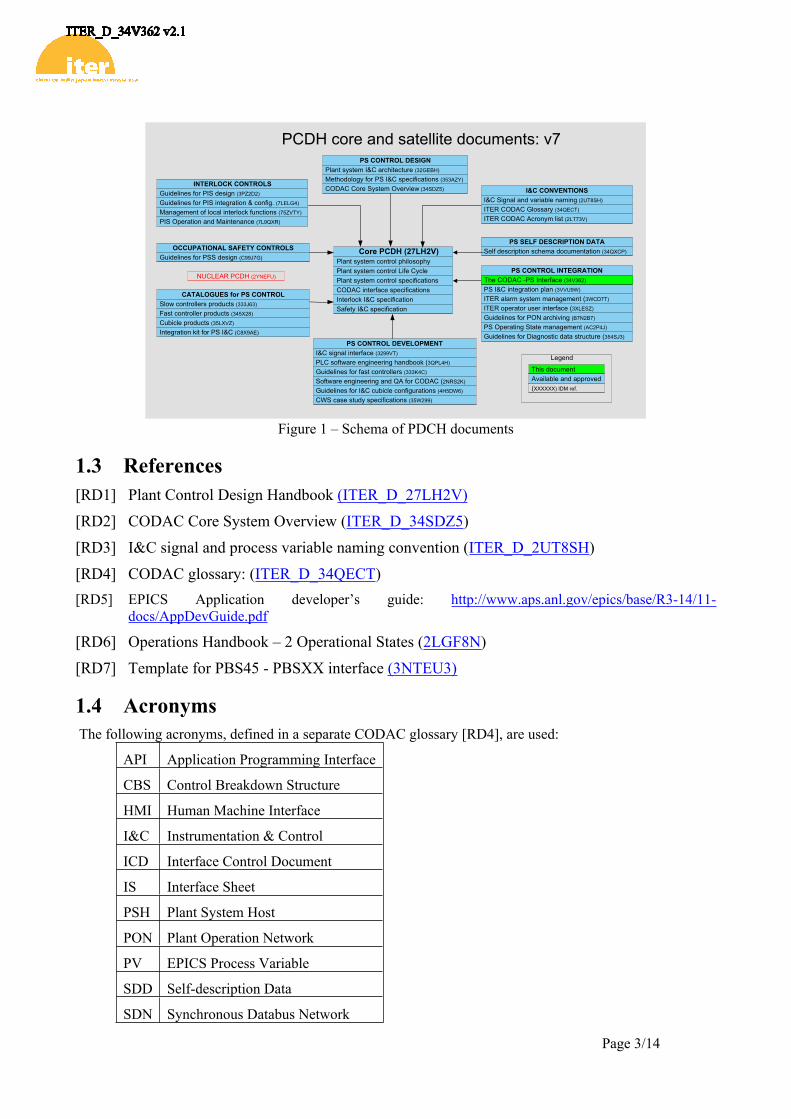
PCDH comprises a core document which presents the plant system I&C life cycle and recaps the main rules to be applied to the plant system I&Cs for conventional controls, interlocks and safety controls. Some I&C topics will be explained in greater detail in dedicated documents associated with PCDH as presented in Figure 1. This document is one of them.
1.2 Scope of the documentThis document is a specification for the interface used to communicate with any ITER plant system from CODAC.
Interlocks and safety are not covered, except for the interlock or safety information that is available in the conventional controllers of the plant systems.
The interface described in this document is implemented in the plant systems controllers and in the PSH.
The interface includes:
Any data of the plant system that can be accessed (set or retrieved) from CODAC.
The commands that the plant system can execute.
The alarms that are detected by the plant system and transmitted to CODAC.
The data that need to be received from CODAC.
Although not detailed in this version, the interface will also include the data and events distributed with the Time Communication Network (TCN) and the Synchronous Data Network (SDN).
The interface definition of each plant system shall include a mandatory part, common to all plant systems. A limited definition of this common interface is included in this version of the document.
The interface specified in this document shall be fully defined in the plant system self-description using the IO supplied tools, such as the SDD tools that are distributed with the CODAC Core System software [RD2].
Page 3/14
Core PCDH (27LH2V)Plant system control philosophyPlant system control Life CyclePlant system control specificationsCODAC interface specificationsInterlock I&C specificationSafety I&C specification
PCDH core and satellite documents: v7PS CONTROL DESIGN
Plant system I&C architecture (32GEBH)
Methodology for PS I&C specifications (353AZY)
CODAC Core System Overview (34SDZ5) INTERLOCK CONTROLS
Guidelines for PIS design (3PZ2D2)
Guidelines for PIS integration & config. (7LELG4)
Management of local interlock functions (75ZVTY)
PIS Operation and Maintenance (7L9QXR)
I&C CONVENTIONSI&C Signal and variable naming (2UT8SH)
ITER CODAC Glossary (34QECT)
ITER CODAC Acronym list (2LT73V)
PS SELF DESCRIPTION DATASelf description schema documentation (34QXCP)
CATALOGUES for PS CONTROLSlow controllers products (333J63)
Fast controller products (345X28)
Cubicle products (35LXVZ)
Integration kit for PS I&C (C8X9AE)
PS CONTROL INTEGRATIONThe CODAC -PS Interface (34V362)
PS I&C integration plan (3VVU9W)
ITER alarm system management (3WCD7T)
ITER operator user interface (3XLESZ)
Guidelines for PON archiving (B7N2B7)
PS Operating State management (AC2P4J)
Guidelines for Diagnostic data structure (354SJ3)PS CONTROL DEVELOPMENT
I&C signal interface (3299VT)
PLC software engineering handbook (3QPL4H)
Guidelines for fast controllers (333K4C)
Software engineering and QA for CODAC (2NRS2K)
Guidelines for I&C cubicle configurations (4H5DW6)
CWS case study specifications (35W299)
NUCLEAR PCDH (2YNEFU)
OCCUPATIONAL SAFETY CONTROLSGuidelines for PSS design (C99J7G)
Available and approved
Legend
This document
(XXXXXX) IDM ref.
The CODAC -PS Interface (34V362)
Figure 1 – Schema of PDCH documents
1.3 References[RD1] Plant Control Design Handbook (ITER_D_27LH2V)
[RD2] CODAC Core System Overview (ITER_D_34SDZ5)
[RD3] I&C signal and process variable naming convention (ITER_D_2UT8SH)
[RD4] CODAC glossary: (ITER_D_34QECT)[RD5] EPICS Application developer’s guide: http://www.aps.anl.gov/epics/base/R3-14/11-
docs/AppDevGuide.pdf
[RD6] Operations Handbook – 2 Operational States (2LGF8N)
[RD7] Template for PBS45 - PBSXX interface (3NTEU3)
1.4 Acronyms The following acronyms, defined in a separate CODAC glossary [RD4], are used:
API Application Programming Interface
CBS Control Breakdown Structure
HMI Human Machine Interface
I&C Instrumentation & Control
ICD Interface Control Document
IS Interface Sheet
PSH Plant System Host
PON Plant Operation Network
PV EPICS Process Variable
SDD Self-description Data
SDN Synchronous Databus Network

Page 4/14
TCN Time Communication Network

Page 5/14
2 PLANT SYSTEM I&C CONFIGURATIONAs defined in the Plant Control Design Handbook [RD1], each plant system I&C consists of one and only one PSH and one or more plant system controller(s) interfacing to plant system components, actuators and sensors, via signal interfaces. Plant system controllers are either fast controllers or PLCs.
With respect to CODAC, each plant system I&C is in charge of implementing a set of functions belonging to the ITER plant functional breakdown.
This role of the plant system I&C is illustrated in Figure 2.
Plant System I&C
PSH
Controller
Controller
Componentsignalsignal
Componentsignalsignal
Implements
Function
Function- commands- variables
Function- commands- variables
Figure 2 – Plant system I&C functional role
Each plant system I&C shall provide the CODAC/Mini-CODAC systems (operator displays, supervision, scheduling system, alarms handling…) with a functional interface implemented by EPICS process variables (PVs).
This interface is bound to the functions implemented by the plant system I&C and, for each function, the interface is composed of a list of commands and variables.
The CODAC interface is part of the plant system I&C configuration that also includes the definition of the signals and the configuration of the PSH and controllers.
2.1 Plant system I&C function identifierThe set of functions implemented by a plant system I&C shall be defined in the ITER Control Breakdown System (CBS).
The ITER functional breakdown is a hierarchical structure. Each level is uniquely identified by an alpha numeric string of maximum 4 characters. A function name is composed with the name of each level separated by a dash (“-“).
The set of functions implemented by a plant system I&C shall belong to the same level 2 function from the ITER CBS. As a result, all these functions shall share the same FFFF-FFFF pattern in their name that is built as: <CBS1>-<CBS2> where CBS1 and CBS2 are CBS identifiers at level 1 and level 2.
2.2 Plant system I&C nameConventionally, a plant system I&C is associated with a CBS level 2 funtion and shall be named accordingly: <CBS1>-<CBS2>.
2.3 Plant system I&C signals nameThe set of signals that a plant system I&C manages shall be defined using IO supplied tools.
Page 6/14
Within a plant system I&C, the signals are identified using their unique name, as defined in the Plant Control Design Handbook [RD1].
Any signal managed by a plant system I&C is named with the identifier of the component to which the signal belongs and the identifier of the signal separated by a colon (“:”).
The component identifier shall comply with the ITER component naming convention.
The signal identifier shall comply with the signal naming convention, as defined in the document “I&C signal and process variable naming convention” [RD3].
The signal name format, compliant with these rules is: PPPP-TTT-NNNN:AAAA[RRRR]-SSS
2.4 Plant system I&C variable nameThe variable name format is: Control Function Identifier : Variable Identifier
The variable identifier is a free string of 16 characters maximum VV…VV, provided the full name including the function identifier is unique within the whole ITER plant. Any alphabetic character used in names shall be in upper case.
The variable name format, compliant with these rules is: FFFF-…….FFFF: VV….VV
2.5 Plant System I&C function deploymentThe functions implemented by a plant system I&C are deployed on plant system I&C controllers and PSH.
It is recommended to have each level 3 function deployed on only one control unit but this is not mandatory.
2.6 Plant system I&C configuration toolsThe Plant system I&C software and the CODAC interface shall be defined using IO supplied configuration tools. The main tool is the SDD editor that is supplied with the Mini-CODAC software.
A plant system I&C configuration data that shall be defined using the SDD editor is composed of:
The list of signals that are interfaced via the plant system I&C.
The list of functions that the plant system I&C implements and, for each function, the complete definition of the function interface (commands and variables).
The configuration of the controllers and PSH, including the configuration of the controllers’ I/O interfaces and the signal connections.

Page 7/14
3 PLANT SYSTEM I&C INTERFACE COMPONENTS
3.1 VariablesIn the interface definition of a plant system I&C, a distinction is made between the configuration of the plant system and its state.
The configuration represents the set of internal values that is the input for the plant system I&C processing and that can only be modified by means of commands (dynamic configuration) or changes in a configuration data-base (static configuration).
The state represents the set of internal values that reflect the current state of the system as maintained by the plant system I&C processing, according to the configuration and the input signals.
Operate
Controller
State
Equipment
Input Signals
Control Equipment
State Variables
Configuration
Output signals
StaticConfiguration
(Self-description)
Configuration Variables
Simple commands
Figure 3 - States and Configuration Data Flows
The interface with a system’s internal data is implemented by means of functional variables that can be read and, conditionally, written by CODAC, and by simple commands that trigger specific action in controllers.
The complete state of a plant system shall be interfaced by means of a set of variables, qualified as state variables.
The complete configuration of a plant system shall be interfaced by means of a set of variables, qualified as configuration variables.
Each variable that belongs to a Plant System I&C interface shall be defined using the SDD editor and shall be deployed on one and only one controller or PSH.
A configuration variable can be qualified as being or not static. If static, its value shall be specified in the variable definition (in SDD); if not, the value can be set by a “put” command (via Channel Access).
By default, the value of a configuration variable is persistent, which means that the value is saved when changed and restored whenever the plant system I&C is restarted.
Optionally, a state variable can be configured to be persistent. This should be restricted to cases in which an acquired value needs to be restored after a controller has been restarted,
A state variable shall be assumed to be dynamic, in the sense that its value can change independently of commands received by the system or component.
Page 8/14
3.2 Variable kindVariables differ with respect to the kind they belong to:
A discrete variable can only have a defined set of values. Its definition includes the specification of each value, consisting in a numeric code and an alphanumeric label. This applies to Boolean values and to enumerations.
A continuous variable has a continuous range of values that may be bound by limits. Its definition includes the data type, the units and may include limits for operation and alarms.
In addition, the value of a variable can be a string of characters and in that case its definition includes the maximum number of characters.
The definition of a discrete variable shall include the exhaustive list of the supported values. The number of values is limited to a maximum of 16. Each value shall be defined with a numeric code, which is an unsigned 16 bit integer, and a character string whose length is limited to a maximum of 16 characters.
The definition of a continuous variable shall include a data type and a unit. If required, design limits shall also be specified.
The definition of a string variable shall include the maximum length of the string. This length cannot be greater than 40 characters.
3.3 Values typeThe supported types for values exchanged via variables are those supported by EPICS records and by channel access. These comprise:
Numeric data types, signed or unsigned integers (8 bits, 16 bits, 32 bits) and floats (32 bits and 64 bits)
Strings, as arrays of maximum 40 bytes,
Scalar values are supported for all the listed data types. Arrays of numeric values and bytes are also supported.
The following attributes are associated with any value received from a monitored variable via channel access:
A time stamp represented in UTC time with a resolution on one nanosecond. The actual precision depends on the time precision of the control unit.
A quality factor (STAT field in EPICS), that indicates, when not null, that the value is not available and that provides a coarse indication of the reason.
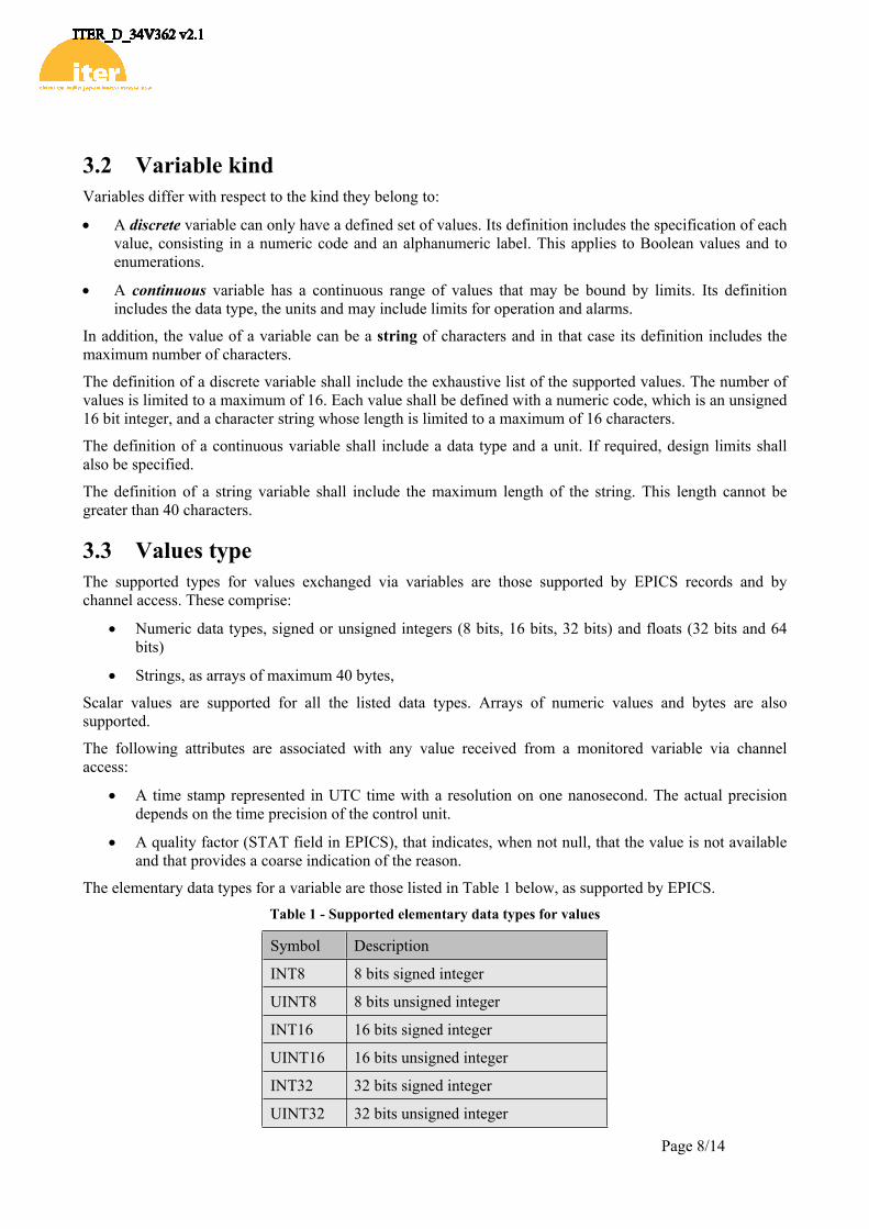
The elementary data types for a variable are those listed in Table 1 below, as supported by EPICS.Table 1 - Supported elementary data types for values
Symbol Description
INT8 8 bits signed integer
UINT8 8 bits unsigned integer
INT16 16 bits signed integer
UINT16 16 bits unsigned integer
INT32 32 bits signed integer
UINT32 32 bits unsigned integer

Page 9/14
FLOAT32 32 bits float
FLOAT64 64 bits float
STRING Byte arrays with max length of 40.
The value data type for discrete variables cannot be configured. UINT16 is the only supported data type.
The value for a continuous variable can be a scalar of any of the elementary data types or a one dimension array of any numeric data type from this list.
The implementation of a state variable shall allow the delivery of a time stamp attribute that shall be at least as accurate as the time precision of the control unit.
3.4 CommandsCommands sent to a plant system I&C are of three types:
Read the value of any variable (state or configuration)
Example: caput TEST-MOT:POSCMD “Open”
Write a new value to a configuration variable.
Example: caput TEST-MOT:POSCMD “Open”
Trigger an action in a controller via a simple command.
Example: caput TEST-MOT:RESET 1
Simple commands are also implemented by means of EPICS PVs and variables in PLCs. The value written must be 1, which signals and indicates a request that is pending for transmission to the PLC or for execution in a fast controller. Once the request has been transmitted or executed, the variable value is reset to 0.
The value written to a configuration variable shall comply with value data type specified in the definition of the variable.
The simple commands that the controllers implement shall be defined in plant system I&C interface. Only the name of the command needs to be specified and conventionally it should be a verb describing the action to be triggered.
3.5 Alarms InterfaceThe purpose of the alarm system is to provide information to the operators through a Mini-CODAC / CODAC system service for fault diagnosis and correction. A plant wide alarm handling policy will be put in place to handle the alarm situations and to undertake corrective action to allow normal and safe operation to continue.
The plant system I&C shall maintain the status of all active alarms and shall transmit any change of this status (alarm raised, alarm cleared).
The alarm shall carry information to the CODAC system to enable alarm reduction.
The alarms shall be raised in accordance with the operating states. This is needed to properly qualify alarms which are not significant in a given situation.
EPICS records generate alarms. The types of alarms fall into the following categories:
scan alarms,
read/write alarms,
Page 10/14
limit alarms,
state alarms.
Some of these alarms are automatically managed by the EPICS device support - scan alarms and read/write alarms. The alarm severity is always set to INVALID for invalid data or no communication.
Limit alarms and state alarms are configured using SDD and are part of the Plant System Interface.
3.5.1 Limit AlarmAlarm limits are configured for analogue records (Analog Input [AI], Analog Output [AO], Calculated PV [CALC]… records). There are two limits for above normal operating range – high-high [HIHI] and high [HIGH] and two limits for the below-limit operating range – low-low [LOLO] and low [LOW] so that a warning can be set off before the value goes into a dangerous condition.
Each of these limits may have an associated alarm severity: MAJOR, MINOR, NO_ALARM or INVALID. If the record's value drops below the low limit and an alarm severity of MAJOR was specified for that low limit, then a MAJOR alarm is triggered. When the severity of a limit is set to NO_ALARM, none will be generated.
Analogue records also contain a hysteresis field, which is used when determining limit violations. The hysteresis field is a dead band around the alarm limits and keeps a signal that is hovering at the limit from generating too many alarms.
3.5.2 State AlarmState alarms are configured for discrete values (Binary Input [BI], Binary Output [BO], Multi-Bit Binary Input [MBBI], Multi-Bit Binary Output [MBBO]…). In this case, a certain state can trigger an alarm with a given severity.
Discrete records also have a specific field (UNSV) used to specify the severity of an unknown state to NO_ALARM, MINOR or MAJOR. If set, the unknown state severity field triggers an alarm when the record support routine cannot find a matching value in the state value fields for VAL or when VAL is out of range.
The change of state severity field (COSV) triggers an alarm when the record's state changes, if set to MAJOR or MINOR. Thus, the operator can be informed when the record's alarm state has changed. If this field specifies NO_ALARM, then a change of state will not trigger a change of state alarm. If specified either MINOR or MAJOR, a change of state will trigger an alarm with the corresponding severity.
3.6 Archiving InterfaceUsing SDD, EPICS analogue records should include the definition of the thresholds and smoothing filter to reduce noise on the input signal. The objective is to define on the EPICS IOC level these necessary parameters to reduce the amount of processing negligible value changes:
ADEL - Archive dead band: limits the values sent to the archive engine to changes beyond this threshold
SMOOTH - constant between 0 and 1 applied to the converted hardware signal, with 0 meaning no smoothing and 1 meaning ultimate smoothing.
Archiving can be enabled/disabled according to a specific variable defined as the “enabling” variable: whenever the value of this variable is above zero, sampling and archiving of a whole group will be enabled until the variable returns to zero or below. The enabling variable should be defined using SDD.
Then for each variable to be archived, the mode should be specified in SDD:
Archiving Monitor Mode: each value sent by the EPICS IOC is stored. With a perfectly configured data source with adequate thresholds that only pass significant changes to the archive engine, this

Page 11/14
mode is ideal and the recommended one. Important changes in value are written to the archive, while noise in the signal is suppressed to minimise wasted resources. The expected change frequency should be specified in SDD as it sizes the memory buffer allocated to the variable by the Archive Engine,
Archiving Monitor with Threshold Mode: each value received is compared by the Archive Engine to the previous one and stored only if the change is greater than the dead band. In this mode, the Archive Engine performs the dead band check in place of the EPICS IOC,
Archiving Scan Mode: the Archive Engine receives each update from the data source but only writes the most recent ones at periodic times. Mode created for PVs which do not have a good dead band configuration and where using monitored mode would add too many data to the archive
3.7 External DataThe data transmitted to the plant system I&C by CODAC from another plant system I&C shall be fully defined. Such data are usually identified in the plant system’s Interface Control Document (ICD) as collaborative data.
Any variable belonging to another system shall be specified and will be made available via a CODAC gateway.
3.8 Error and Trace loggingThe log messages are handled by log servers that record all messages in files. Operators and experts shall be able to obtain from these log files the details of an abnormal behavior, for diagnostic purposes.
The plant system I&C shall provide information on its normal and abnormal behavior by means of log messages, as defined in the Plant Control Design Handbook.
The processing code implemented in controllers and in PSH shall log such messages by using an error logging API that is part of EPICS and defined in the EPICS Application programmers guide [RD5].
The log information that shall be transmitted via the API is:
A log severity, which shall be specified when calling the API: Info, Minor, Major, Fatal.
A text of maximum 255 characters.
By convention, the text of the message shall include the name of the function involved.
In addition, a time stamp is automatically added by the client API into the log message.
Error messages shall provide details of faults detected by a controller. However, the fault itself shall be signaled by means of a variable that maintains the state of the fault as active or not and that shall activate/deactivate the generation of an alarm.
Page 12/14
4 STANDARD INTERFACE DATAThe CODAC interface includes some standard variables that shall be implemented by each plant system I&C.
The IO supplied tools will enforce the presence of such variables and will provide the capacity to configure them. Except where explicitly mentioned, all these variables shall be implemented in the plant system I&C.
The current list is limited to the minimum set of variables supporting standard features defined in the Plant Control Design Handbook.
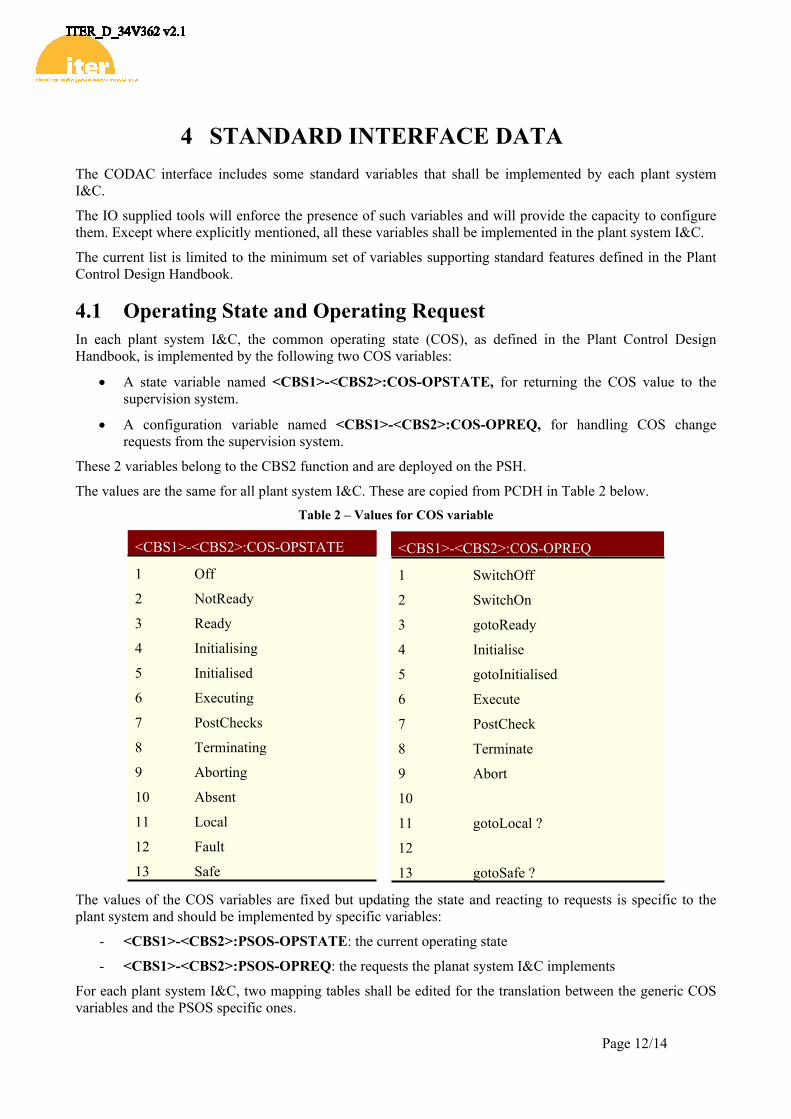
4.1 Operating State and Operating RequestIn each plant system I&C, the common operating state (COS), as defined in the Plant Control Design Handbook, is implemented by the following two COS variables:
A state variable named <CBS1>-<CBS2>:COS-OPSTATE, for returning the COS value to the supervision system.
A configuration variable named <CBS1>-<CBS2>:COS-OPREQ, for handling COS change requests from the supervision system.
These 2 variables belong to the CBS2 function and are deployed on the PSH.
The values are the same for all plant system I&C. These are copied from PCDH in Table 2 below.Table 2 – Values for COS variable
<CBS1>-<CBS2>:COS-OPSTATE
1 Off
2 NotReady
3 Ready
4 Initialising
5 Initialised
6 Executing
7 PostChecks
8 Terminating
9 Aborting
10 Absent
11 Local
12 Fault
13 Safe
<CBS1>-<CBS2>:COS-OPREQ
1 SwitchOff
2 SwitchOn
3 gotoReady
4 Initialise
5 gotoInitialised
6 Execute
7 PostCheck
8 Terminate
9 Abort
10
11 gotoLocal ?
12
13 gotoSafe ?
The values of the COS variables are fixed but updating the state and reacting to requests is specific to the plant system and should be implemented by specific variables:
- <CBS1>-<CBS2>:PSOS-OPSTATE: the current operating state
- <CBS1>-<CBS2>:PSOS-OPREQ: the requests the planat system I&C implements
For each plant system I&C, two mapping tables shall be edited for the translation between the generic COS variables and the PSOS specific ones.
Page 13/14
4.2 System monitoring functionIn each plant system I&C, one level 3 function is standardized for the management and monitoring of the plant system I&C. This function is added into each plant system I&C by CODAC configuration tools with automatically generated variables. This function is named <CBS1>-<CBS2>-SYSM
The system monitoring function currently includes the following:
- Monitoring the resource of the control units, such as memory, CPU or network and triggering alarms when resource usage limits are crossed.
- Monitoring the health of the required software processes and triggering alarms on detection of abnormal behavior.
- Monitoring the communication status with PLCs
- Monitoring the cubicle conditions (temperature, door status …)
4.3 SimulationIt is recommended to interface any simulation mode that a plant system I&C supports by meqns of a simulation option variable in a dedicated CBS3 function named SIM.
A simulation option: <CBS1>-<CBS2>-SIM:<option_name> is a Boolean configuration variable (bo record) that controls the activation of a simulation mode.
It is planned, in a future version of the configuration tools, to add a global simulation state reflecting the activation of any simulation option.
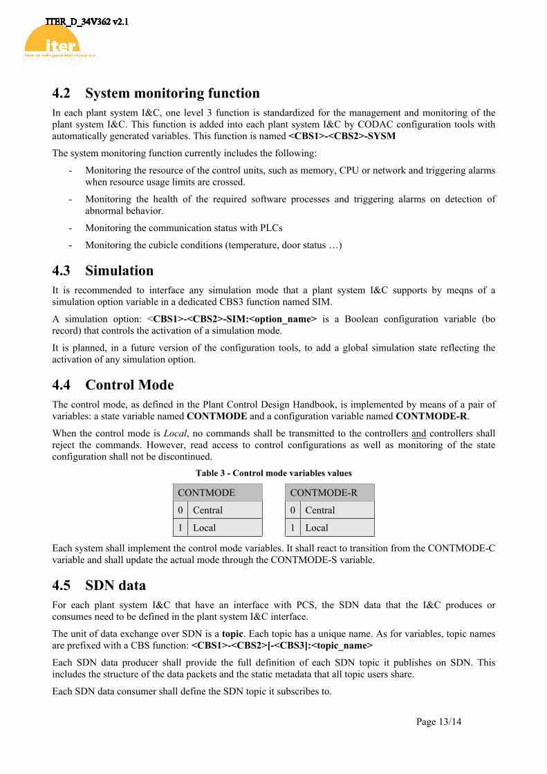
4.4 Control ModeThe control mode, as defined in the Plant Control Design Handbook, is implemented by means of a pair of variables: a state variable named CONTMODE and a configuration variable named CONTMODE-R.
When the control mode is Local, no commands shall be transmitted to the controllers and controllers shall reject the commands. However, read access to control configurations as well as monitoring of the state configuration shall not be discontinued.
Table 3 - Control mode variables values
CONTMODE CONTMODE-R
0 Central 0 Central
1 Local 1 Local
Each system shall implement the control mode variables. It shall react to transition from the CONTMODE-C variable and shall update the actual mode through the CONTMODE-S variable.
4.5 SDN dataFor each plant system I&C that have an interface with PCS, the SDN data that the I&C produces or consumes need to be defined in the plant system I&C interface.
The unit of data exchange over SDN is a topic. Each topic has a unique name. As for variables, topic names are prefixed with a CBS function: <CBS1>-<CBS2>[-<CBS3]:<topic_name>
Each SDN data producer shall provide the full definition of each SDN topic it publishes on SDN. This includes the structure of the data packets and the static metadata that all topic users share.
Each SDN data consumer shall define the SDN topic it subscribes to.

Page 14/14
5 INTERFACE SHEETThe CODAC – Plant System I&C interface set of data is made of the configuration data of the interface components as specified in chapter 3 and of the standard interface data as specified in the chapter 4.
When the plant system I&C is manufactured, this data is produced using SDD tools and maintained in SDD databases.
Beforehand, the interface definition is recorded in Interface Sheets (IS) that are part of the Interface Control Document with CODAC.
To allow data transfer from the IS to the CODAC configuration databases used during design (PSP) and implementation (SDD), these IS should be provided as structured excel tables.
A template is provided for producing structured IS with CODAC [RD7].
![Public Procurement in Kenya’s Counties · 2019-03-10 · viii 1 TransparencyInternational[TI].(2014).Public procurement in Kenya: Cash cow for the corrupt or enabler for public](https://static.fdocuments.in/doc/165x107/5e5386874d852a3a55240037/public-procurement-in-kenyaas-counties-2019-03-10-viii-1-transparencyinternationalti2014public.jpg)


![Technical Specifications (In-Cash Procurement) VALVES ...fusionforenergy.europa.eu/downloads/procurements/itercalls/572/... · [2.18] ASME B1.1-2003, “Unified Inch Screw Threads,](https://static.fdocuments.in/doc/165x107/5b5034b27f8b9a206e8e0910/technical-specifications-in-cash-procurement-valves-218-asme-b11-2003.jpg)