
TECHNICAL SPECIFICATIONS FOR ACCESS ROAD AND WELL …
28
1 <TITLE OF THE PROJECT> TECHNICAL SPECIFICATIONS FOR ACCESS ROAD AND WELL PAD (DRAFT) 1. PURPOSE This technical specification is prepared for construction of access road and well pads for Test Well Drilling Project for Geothermal Development in Djibouti (hereinafter called as “The Project”), to drill two (2) geothermal test wells at Hanle Garabbayis area in Dikhil District, Djibouti under JICA’s technical cooperation. 2. SCOPE OF WORK This technical specification is limited to access road construction and geothermal well pad preparation for the Project. The main contents of the work are shown in Table-1; Table-1 Scope of Work Contents Work Items A. Access Road Construction A-1 Clarification of Alignment A-2 Clearing and Grubbing A-3 Cutting A-4 Embankment A-5 Paving of Gravel A-6 Drainage B. Base camp and Well Pad Preparation B-1 Clarification of Area B-2 Clearing and Grubbing B-3 Cutting B-4 Embankment B-5 Laying of Gravel B-6 Construction of Water Pit B-7 Construction of Sump Pit B-8 Lining of Water pit and Sump pit B-9 Concrete Works B-10 Fencing
Transcript of TECHNICAL SPECIFICATIONS FOR ACCESS ROAD AND WELL …

1
<TITLE OF THE PROJECT>
TECHNICAL SPECIFICATIONS FOR ACCESS ROAD AND WELL PAD
(DRAFT)
1. PURPOSE
This technical specification is prepared for construction of access road and well pads for Test Well
Drilling Project for Geothermal Development in Djibouti (hereinafter called as “The Project”), to
drill two (2) geothermal test wells at Hanle Garabbayis area in Dikhil District, Djibouti under
JICA’s technical cooperation.
2. SCOPE OF WORK
This technical specification is limited to access road construction and geothermal well pad
preparation for the Project. The main contents of the work are shown in Table-1;
Table-1 Scope of Work
Contents Work Items
A. Access Road
Construction
A-1 Clarification of Alignment
A-2 Clearing and Grubbing
A-3 Cutting
A-4 Embankment
A-5 Paving of Gravel
A-6 Drainage
B. Base camp and Well Pad
Preparation
B-1 Clarification of Area
B-2 Clearing and Grubbing
B-3 Cutting
B-4 Embankment
B-5 Laying of Gravel
B-6 Construction of Water Pit
B-7 Construction of Sump Pit
B-8 Lining of Water pit and Sump pit
B-9 Concrete Works
B-10 Fencing

2
3. TECHNICAL SPECIFICATIONS
A. Access Road Construction
General
This work shall consist of the excavation/cutting, forming embankment, placement, grading and
compaction of base course material, paving and drainage for access road.
The access road is connected from the national road No.1 to the well pad A-1, A-2, and A-3, with
total length of 4,222m. The road is planned of single track with the nominal width 5 m in principle,
associated with widened double truck stretches (Side lay-by) of the nominal width 8 m for dual
traffic. The side lay-by sections are planned to be constructed approximately on every 500m of
the access road and 50m length each.
The bearing capacity of the access road shall be specified in the standard for the transportation by
20-ton class trailers. The road is normally paved with gravel of 50 cm.
The road was designed concordant with the original ground to minimize the effect to the
environment and to keep low road gradient (maximum gradient is 6.3%). Concrete pipe culverts
with 300mm in diameter are placed under the road material at wadi sections (three sections) to
discharge the surface water flow. The detail of access road is shown in Table-2.
Table-2 Detailed Information on Access Roads
From To Width
(m)
Length
(m)
Maximum
Gradient
(%)
No of Side
Lay-by
Entrance from
National Road No.1
Junction Point (Near
the entrance of camp
site)
5.0 1,280.00 1.958 1
Junction Point Entrance of Pad A-1 5.0 1,709.01 6.307 2
Entrance of Pad A-1 Entrance of Pad A-2 5.0 328.58 5.714 0
Junction Point Entrance of Pad A-3 5.0 904.18 3.107 1
Progress Control and Inspection
All the works as earth works, paving and drainage works shall be controlled by the Contractor by
time to time whether the measured values meet the original drawings as specified.
Periodical inspections shall be conducted by the Contractor to reports the progress, and the Client
shall clarify the values to meet the drawings by using topographic/leveling equipment. Before the
completion of all the works, the Contractor shall be inspected at site by elevation of access road
and all well pads in the presence of the Client. If the tolerance is more than 5cm, the Client may
direct to the Contractor to meet the level to the drawings.
The Contractor shall submit the “completion drawing” when all the site inspections are passed by
the Client.

3
A-1 Clarification of Alignment
The Contractor shall carry out the topographic survey to clarify the road alignment and mark the
alignment at the sit by paint or peg. Based on the results, the Contractor submit shop drawings
to the Client for approval and visual clarification at the site.
A-2 Clearing and Grubbing
This work shall consist of all clearing and grubbing necessary for the performance of the works
covered by the contract in accordance with the specifications. The areas to be cleared, grubbed
and stripped shall be the areas designated in the drawings or the contract documents. It shall also
include the demolition, removal and disposal of structures that obtrude on or encroach upon or
obstruct the work, except where otherwise provided.
The Contractor shall carry out the clearing and grubbing works of the designated areas
considering the bushes, trees, hedges and boulders, shall be grubbed up and disposed off the site
by the Contractor.
Clearing and grubbing shall be performed within the construction width minimizing ground
disturbance as designated in the drawings. The cutting and removal work of plants in the site shall
be done as per the prevailing rules and regulations in Djibouti.
Existing roads, facilities, public utilities, services, and plants earmarked for preservation shall be
protected from harm or damage from the Client's operation.
A-3 Cutting
(1) General
This work shall consist of the excavation to make slope for access road and well pad. The
classification of soil excavation shall be done as the following manners:
Rock: Medium-hard to hard basaltic rock is distributed in the area then slope gradient
of 55 degree (1:0.7) is applied. The rock can be effectively excavated by ripping
with a bulldozer, breaker and static expansive demolition agent. Boulders should
be removed if it is located at shoulder of cutting slope.
Common soil: Sand or sandy soft soil which is combined in the gravel then slope gradient of 45
degree (1:1.0) is applied. The soil which can be effectively removed by shovel
excavator or bulldozers.
(2) Equipment
The Contractor shall prepare adequate equipment to carry out suitable excavation works as
prescribed in the specifications.

4
(3) Construction Method
The excavation shall be carried out with provision of partial protection or shall be compensated
where deemed necessary to prevent from any damages to public utilities. No blasting operations
shall be carried out without permission from the Client. The Contractor shall carry out blasting
works in conformity with enforced regulations in Djibouti. Any damage to third parties outside
of the construction area caused under this work shall be compensated for at the Contractor’s
expense.
The excavated rock larger than 30 or 50cm shall be broken up to less than 30 to 50 cm in diameter.
The material excavated and broken up shall be loaded to a delivery vehicle.
Excess excavation in cut sections shall be refilled with suitable material without extra
measurement and payment. If so, the Contractor shall remove unsuitable excavated materials for
use in embankment and dispose it off. The disposed materials shall be removed, hauled and
stocked in a stock yard as waste prepared by the Contractor. As a minimum requirement, the
Contractor shall undertake slope stabilization measures for spoil banks on governmental lands.
For spoil banks on land prepared by the Contractor, the Contractor himself shall be responsible
for stabilizing them.
A-4 Embankment
(1) General
This work shall cover all embankment works for earth structures to be constructed for access
road and well pads as shown in the drawings which includes the following operations:
1) Preparation of foundation for embankment,
2) Placing and compaction of embankment materials, and
3) Quality control on embankment materials.
(2) Materials
All materials excavated by making access road and well pads shall be effectively used for the
embankment, except unsuitable materials such as top soil including organic soil and plants. The
Contractor shall control the quality on embankment materials by removing organic soil and plants
when it is excavated.
(3) Equipment
The Contractor shall prepare adequate equipment to carry out suitable embankment works as
prescribed in the specifications.

5
(4) Construction Method
1) Preparation of foundation
No material shall be placed in any section of the embankment site until the foundation has been
suitably prepared in a manner approved by the visual check. The Contractor shall check the
ground conditions, and if necessary, remove unstable ground or compact loosen parts to be firm
before embankment work. Any damage to a third party outside of the construction area caused
under this work shall be compensated for at the Contractor’s expense.
Preparation of the foundation for the embankment shall be checked by the Client. If the condition
of the foundation is not satisfactory, the Contractor shall implement additional work.
2) Placing and compaction of embankment materials
Because the excavated rock size differs from fine soils to boulders, the Contractor shall check the
size of excavated rock size broken up to less than 30 to 50 cm at excavation. Excavated rocks
shall be moved to the nearest embankment areas by bulldozer and/or dump tracks.
Compaction shall be conducted by rollers on the embankment with grading.
Any rock fragments found in the placed material which is larger than 30 to 50 cm shall be removed
or crushed before the material is compacted.
(5) Quality control on embankment materials
The Contractor perform the field and laboratory tests on embankment materials, provide a trained
staff to the satisfaction of the Client, to conduct all necessary tests to ensure that the embankment
materials satisfy all requirements of the specifications.
Soil tests shall be conducted at embankment points where the surface is composed of
embankment to investigate the strength of the ground of well pad. The test shall be conducted
after placing of embankment material before compacting. The test shall be complying with
ASTM D 1586 (Standard penetration test) and conducted at the following locations on the
access road:
- P17, P49, P86, P141, P145, p32, p41, p43 (eight points)
Field and laboratory tests on embankment materials shall be in accordance with testing methods
and recommended practices of the American Society for Testing and Materials (ASTM D1557).
The minimum control value shall be not less than 90% of the density of compaction of original
embankment material, and not less than 85 % of saturation of original of embankment material.

6
A-5 Paving
(1) General
This work shall consist of preparation of gravel (crushed stone) and sand material treatment
of access road surface, hauling, spreading and compacting the materials on excavated and/or
embanked base, in accordance with these specifications and the lines, levels, grades,
dimensions and cross sections shown in the drawings.
(2) Materials
Materials for gravel shall be sound, durable crushed rocks, boulders and stones blended with
natural coarse sand, the combined grading of which shall be within the following specified
limit as shown in Table-3:
Table-3 Particle Size Distribution for Gravel
Sieve size Total percent passing
50.8 mm 100
25.4mm 70 - 90
19.1mm 50 - 85
4760 µ 25 - 60
420 µ 10 - 30
74 µ 0 - 15
(3) Construction Method
1) Preparation
Any ruts, holes, defects or soft, yielding places that occur in the base by reason of any improper
drainage condition, traffic or hauling over of the same or for any other cause, shall be corrected
and compacted to the required stability and complied with the smoothness.
2) Spreading
Gravel shall be spread in layers of not over 15 cm compacted thickness and compacted with
bulldozers and/or shovel excavators.
After the gravel has been spread and before compaction begins, the edges shall be backed up
with sub-base materials to such a height that the sub-base in shoulder portion will be
compacted to the height of the course as shown in typical cross section of the drawings.

7
3) Compaction
Compaction of gravel shall be done after spreading operation and roller shall begin at the edge
of the layer. The rolling shall be from the low side to the high side. Water in the amount that
is necessary for achieving the required compaction shall be added during rolling.
Any irregularities that develop in the surface of the gravel during rolling shall be corrected by
loosening the surface, adding or removing material and re-compacting until the surface
presents a smooth regular appearance. Gravel shall be compacted to the thickness and cross
section as shown on the drawings and shall not vary by more than 10 cm from the required
elevation. All humps and depressions and thickness deficiencies exceeding the tolerances of
more than 5cm shall be corrected by removing the defective work or by adding new material.
4) Inspection and Tests
The Contractor shall report the progress of compacting work to the Client every week by
construction report, and the Client check the compacting procedure and compacted surface
based on at the site. The Contractor shall propose the tests of compacted surface in accordance
with testing methods and recommended practices of the American Society for Testing and
Materials (ASTM D1557). The minimum control value shall be not less than 90% of the
density of compaction of original embankment material, and not less than 85 % of saturation
of original of embankment material.
A-6 Drainage
(1) General
This work shall consist of construction of crossing structure of seasonal stream (wadi) drain
and underpass for water supply pipeline. Precast concrete culvert is applied for this work, to
be put to the place specified in the drawings.
(2) Material
Precast concrete pipe shall be procured to ensure the strength which shall comply with ASTM
C1417–15 or equivalent. For river crossing and passing for water supply pipeline, thickness of
wall shall not be less than 30mm and bearing strength shall be not less than 17.7 kN/m. The
surface of the finished units shall be smooth, dense and hard with clean sharp arises (except where
otherwise indicated) and shall be free from cracks, discoloration, holes, fins, honeycombing,
watermarks, dusting or shutter marks.
(3) Construction Method
Units shall be manufactured and cured in a properly equipped casting yard or shop and the
arrangements shall be subject to the inspection and approval of the Client. The Contractor shall
give adequate notice to the Client before dispatching precast units to the site and, if the Client so
8
requires, shall provide facilities for inspection, test loading and dimensional checking of the units
before they are dispatched. In case the units are constructed in a factory or yard remote from
the site, details of the concrete components, mix design and compression test results shall be made
available to the Client. Details of the design shall be subject to approval by the Client as required.
Special lifting arrangements shall be incorporated in the design to eliminate damage to arises and
surfaces during handling and erection.
The Contractor shall mark and identify the points where the underpass is constructed before
embankment work is commenced. Gravel with sand shall be laid as a foundation. Concrete pipes
shall be set at the bottom of embankment and connected all by mortar before the embankment
work is commenced. The embankment or backfill rocks shall be smaller, less than 15cm around
the concrete pipes not to give damage the pipe. Compaction shall not be done until the thickness
of embankment is reached 1.0m above underpass.
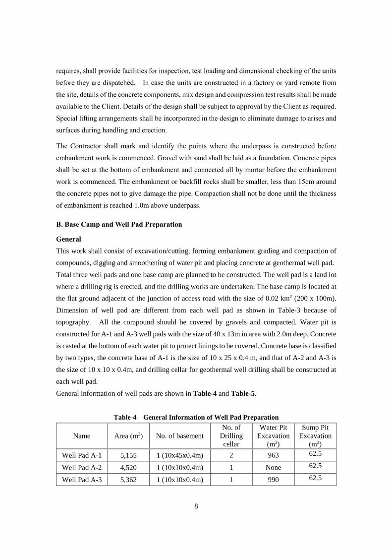
B. Base Camp and Well Pad Preparation
General
This work shall consist of excavation/cutting, forming embankment grading and compaction of
compounds, digging and smoothening of water pit and placing concrete at geothermal well pad.
Total three well pads and one base camp are planned to be constructed. The well pad is a land lot
where a drilling rig is erected, and the drilling works are undertaken. The base camp is located at
the flat ground adjacent of the junction of access road with the size of 0.02 km2 (200 x 100m).
Dimension of well pad are different from each well pad as shown in Table-3 because of
topography. All the compound should be covered by gravels and compacted. Water pit is
constructed for A-1 and A-3 well pads with the size of 40 x 13m in area with 2.0m deep. Concrete
is casted at the bottom of each water pit to protect linings to be covered. Concrete base is classified
by two types, the concrete base of A-1 is the size of 10 x 25 x 0.4 m, and that of A-2 and A-3 is
the size of 10 x 10 x 0.4m, and drilling cellar for geothermal well drilling shall be constructed at
each well pad.
General information of well pads are shown in Table-4 and Table-5.
Table-4 General Information of Well Pad Preparation
Name Area (m2) No. of basement
No. of
Drilling
cellar
Water Pit
Excavation
(m3)
Sump Pit
Excavation
(m3)
Well Pad A-1 5,155 1 (10x45x0.4m) 2 963 62.5
Well Pad A-2 4,520 1 (10x10x0.4m) 1 None 62.5
Well Pad A-3 5,362 1 (10x10x0.4m) 1 990 62.5

9
Table-5 Well Pad Location (UTM 38N)
Name Corners of Well Pad
X Coordination Y Coordination
Well Pad A-1
191761.58 1262278.87
191843.17 1262244.74
191810.24 1262300.03
191761.58 1262323.25
191780.82 1262324.76
Well Pad A-2
192145.06 1262533.53
192067.62 1262517.21
192058.09 1262463.27
192156.45 1262485.19
Well Pad A-3
191010.13 1263334.99
191049.16 1263303.74
191091.92 1263356.76
191115.02 1263402.87
191093.45 1263419.96
191051.13 1263386.16
Progress Control and Inspection
All the works as earth works and laying of gravels shall be controlled by the Contractor by time
to time whether the measured values meet the original drawings as specified.
Periodical inspections shall be conducted by the Contractor to reports the progress, and the Client
shall clarify the values to meet the drawings by using topographic/leveling equipment. Before the
completion of all the works, the Contractor shall be inspected by elevation of all the geothermal
well points and all the corners of well pad, dimension and depth of water pits and sump pits in the
presence of the Client. If the tolerance is more than 5cm, the Client may direct to the Contractor
to meet the level to the drawings.
The Contractor shall submit the “completion drawing” when all the site inspections are passed by
the Client.
B-1 Clarification of Area
The Contractor shall carry out topographic survey to clarify the area to be constructed and mark
all the corners by paint or peg. Based on the results, the Contractor submit shop drawings to the
Client for approval and visual clarification at the site.
B-2 Clearing and Grubbing
(Description is as same as A-2 Clearing and Grubbing)
B-3 Cutting
(Description is as same as A-3 Cutting)

10
B-4 Embankment
(Description is as same as A-4 Embankment)
B-5 Laying of Gravel
(1) General
This work shall consist of preparation of gravel (crushed stone) and sand material treatment
of well pad surface, hauling, spreading and compacting the materials on excavated and/or
embanked base, in accordance with these specifications and the lines, levels, grades,
dimensions and cross sections shown in the drawings.
(2) Materials
Materials for gravel shall be sound, durable crushed rocks, boulders and stones blended with
natural coarse sand, the combined grading of which shall be within the specified limit as shown
in Table-3 in previous Section A-5.
(3) Construction Method
1) Preparation
Any ruts, holes, defects or soft, yielding places that occur in the base by reason of any improper
drainage condition, traffic or hauling over of the same or for any other cause, shall be corrected
and compacted to the required stability and complied with the smoothness.
2) Spreading
Gravel shall be spread in layers of not over 15 cm compacted thickness and compacted with
bulldozers and/or shovel excavators.
3) Compaction
Compaction of gravel shall be done after spreading operation and roller shall begin at the edge
of the layer. The compaction shall be from the low side to the high side. Water in the amount
that is necessary for achieving the required compaction shall be added during rolling.
Any irregularities that develop in the surface of the gravel during rolling shall be corrected by
loosening the surface, adding or removing material and re-compacting until the surface
presents a smooth regular appearance. Gravel shall be compacted to the thickness and cross
section as shown on the drawings and shall not vary by more than 10 cm from the required
elevation. All humps and depressions and thickness deficiencies exceeding the tolerances of
more than 5cm shall be corrected by removing the defective work or by adding new material.

11
4) Testing
a) Test for Embankment
Standard penetration tests shall be conducted to investigate the strength of the ground of well
pad. The test shall be conducted after placing of embankment material before compacting. The
test shall be complying with ASTM D 1586 (Standard penetration test) and conducted at the
following locations:
Well Pad A-1: at location of cellar of GB-3, another cellar, embankment part of south-western
and north-western side of well pad (4 locations)
Well Pad A-2: at location of Cellar, embankment part of northern and western side of well pad
(3 locations)
Well Pad A-3: at location of Cellar (pad area will be mainly composed of rock surface)
If the ground strength is less than N = 30, the location shall be excavated at the depth which
strength is upper than N = 30 and replaced to the gravel materials that are specified by A-5
(2). Then, the additional test shall conduct again at the same point whether the required value
(N=30) is secured.
b) Test for compaction of gravel
Compaction tests shall be conducted on the same place of standard penetration test in accordance
with testing methods and recommended practices of the American Society for Testing and
Materials (ASTM D1557). The minimum control value shall not be less than 90% of the density
of compaction of original material, and not less than 85 % of saturation of original material.
B-6 Construction of Water Pit
(1) General
This work shall consist of excavation of water pits on the well pad A-1 and A-3, compacting
pit walls, and casting of concrete at the bottom in accordance with these specifications and the
lines, levels, gradients, dimensions and cross sections shown in the drawings. The work shall
be conducted during or after well pad construction.
(2) Construction Method
The bottom and side slopes of common excavation upon or against which structures are to be
placed shall be finished accurately to the established lines and grades, and loose materials on the
surface so prepared shall be tampered with suitable tools and equipment to form a firm foundation
for the structures. The side slope shall be 45 degree and maximum depth shall be set concordant
with the Drawings.
After the excavation, concrete shall be casted at the bottom of the pit with the thickness shown in
12
the drawings.
If, at any point, excavation is made beyond the established lines, the over excavation shall be
filled with excavated materials which shall be approved and thoroughly compacted by tamping
or rolling to smoothen the surface not to give damage to lining materials to be covered.
If, at any point, hard rock is appeared less than the depth of 2.0m during excavation, adjust the
excavation volume to meet the amount for excavation volume up to the planned excavation
volume (as shown in Table-4) by widening excavation area or banking of pit by excavated soils.
B-7 Construction of Sump Pit
(1) General
This work shall consist of excavation of sump pits on the well pad A-1, A-2 and A-3, compacting
pit walls, and plastering of mortar at the bottom and walls in accordance with these specifications
and the lines, levels, gradients, dimensions and cross sections shown in the drawings. The work
shall be conducted during or after well pad construction.
(2) Construction Method
The bottom and side slopes of common excavation upon or against which structures are to be
placed shall be finished accurately to the established lines and grades, and loose materials on the
surface so prepared shall be tampered with suitable tools and equipment to form a firm foundation
for the structures. The side slope shall be 45 degree and maximum depth shall be set concordant
with the Drawings.
If, at any point, excavation is made beyond the established lines, the over excavation shall be
filled with excavated materials which shall be approved and thoroughly compacted by tamping
or rolling to smoothen the surface not to give damage to lining materials to be covered.
If, at any point, hard rock is appeared less than the depth of 2.0m during excavation, adjust the
excavation volume to meet the amount for excavation volume up to the planned excavation
volume (as shown in Table-4) by widening excavation area or banking of pit by excavated soils.
(3) Plastering of Mortar
After the excavation, meshed iron wire shall be covered at the bottom and the wall of the pit prior
to casting mortar.
Mortar shall be composed of fine aggregate complying with BS 882, BS 1199, BS 1200 or
equivalent, and ordinary Portland cement complying with BSEN 197-1:2000 or equivalent. The
mix proportions shall be one (1) part of cement to three (3) parts of fine aggregate by weight and
mechanical mixer shall be used to mix. The water content of the mortar shall be as low as possible
consistent with the use for which is required, but in any case the water/cement ratio shall not be
more than 0.5.

13
Mortar shall be plastered to more than 10cm by the machine or hand, and the surface shall be
finished smoothly without any cracks. The curing process shall be referred to B-9 (4) 9) Curing
of Concrete.
B-8 Lining of Water pit and Sump pit
(1) Material
Lining materials shall be fulfilled with the following requirements;
1) Materials
Material shall be HDPE or LLDPE and its property of material are shown below;
Table-6 Material to be used for Lining
Property Test Method HDPE LLDPE
Density (g/cm3) ASTM D 1505 >0.932 >0.915
Melt Flow Index (g/10 min) ASTM D 1238 (190/2.16) <1.0 <1.0
OIT (minutes) ASTM D 3895 (1 atm/2000C) >100 >100
2) Thickness: Not less than 1.5 mm
3) Joining: heating or adhesion
(2) Lining at pit bottom and slope
Lining material should be confirmed if there are holes or damages prior to the lining, and pit
slopes should be checked and removed if the sharp materials or angular gravels in surface not to
damage the linings. Additional tempering/rolling should be necessary if pit bottom and/or slope
are soft and rough.
The general information of pits are shown in Table-7.
Table-7 General Information of Pits
Name Dimension (m) Depth (m) Slope (deg) Inner Area (m2)*
Water pit A-1 50.0 x 12.0 2.0 45 820
Water pit A-3 40.0 x 15.0 2.0 45 795
Sump pit A-1 12.0 x 7.0 2.0 45 147
Sump pit A-2 12.0 x 7.0 2.0 45 147
Sump pit A-3 12.0 x 7.0 2.0 45 147
*Margin is not included
(3) Jointing
Jointing shall be conducted with appropriate method for lining materials, as heating or adhesion.

14
After the jointing, visual inspection shall be necessary to clarify the work and defaulted parts.
(4) Fixing
The linings shall be fixed properly by weights or some other materials/equipment not to be moved
or damaged. In case of using anchor pin, it shall be used above the normal water level.
B-9 Concrete Works
(1) General
This work shall cover all concrete works for earth structures to be constructed for well pads
as shown in the drawings which includes the following operations:
1) Classification and required strength,
2) Placing and casting
3) Quality control
(2) Material
1) Cements
Cement shall comply with BSEN 197-1:2000 Ordinary and rapid hardening Portland Cement or
equivalent. Cement in bags shall be stored in a suitable weatherproof structure of which the
interior shall be dry and well ventilated at all times. The floor shall be raised above the
surrounding ground level and shall be so constructed that no moisture rises through it.
Each delivery of cement in bags shall be stacked together in one place. The bags shall be closely
stocked so as to reduce air circulation but shall not be stocked against an outside wall.
All cement used on the works shall be tested by the manufacturer or the Contractor in a laboratory
acceptable to the Client. The tests to be performed shall be those set out in BSEN 197-1:2000
or equivalent.
The Contractor shall keep full records of all data relevant to the manufacturer, delivery, testing
and use of all cement used in the Works and shall provide the Client with two (2) copies thereof.
An additional requirement is that the Portland cement shall have a guaranteed equivalent alkali
content not exceeding 0.6% expressed in the acid soluble alkali content of the cement.
2) Fine aggregate
Fine aggregate shall be clean, hard and durable and shall be natural sand, crushed gravel sand or
crushed rock sand complying with BS 882 or equivalent. To achieve an acceptable grading, it
may be necessary to blend materials from more than one source. Fine aggregate for mortar only
shall comply with BS 882, BS 1199, BS 1200 or equivalent. The fine aggregate shall be
15
reasonably graded.
The fine aggregate shall not contain iron pyrites or iron oxides. It shall not contain mica, shale,
coal or other laminar, soft or porous materials or organic matter unless the Contractor can show
by comparative tests, on finished concrete as set out in BS 1881, that the presence of such
materials does not adversely affect the properties of the concrete.
Other properties shall be as set out below:
(a) Chloride soluble in a 10 per cent solution by weight of nitric acid shall not exceed 0.05
per cent by weight expressed as chloride ion when tested as set out in BS 812, subject also to the
further restriction on total chloride content in Sub-clause III-1-2 (2).
(b) Sulphate soluble in a 10 percent solution by weight of hydrochloric acid shall not exceed
0.4 per cent by weight expressed as SO3, when tested as set out in BS 1377, subject also to the
further restriction given in the note on total sulphate content in Sub-clause III-1-2 (2).
(c) Soundness
After five (5) cycles of the test in AASHO T104, the aggregate shall not show a weight loss of
more than 10 percent.
(d) Organic impurities
The amount of deleterious substance in fine aggregate shall not exceed the limits prescribed
below:
Percent by weight
- Clay lump 1.0
- Material passing 0.074mm sieve 3.0
- Material retained on a 0.297mm sieve and floating
on a liquid having a specific gravity of 2.0 0.5
3) Coarse aggregate
Coarse aggregate shall be clean, hard and durable crushed rock, crushed gravel or natural gravel
complying with the requirements of BS 882 or equivalent. The material shall not contain any
iron pyrites, iron oxides, flaky or laminated material, hollow shells, coal or other soft or porous
material, or organic matter unless the Contractor can show by comparative tests on finished
concrete as set out on BS 1881 that the presence of such materials does not adversely affect the
properties of the concrete. The pieces shall be angular rounded or irregular as defined in BS 812
Part 1 or equivalent.
Coarse aggregate shall be supplied in the nominal sizes called for in the Specifications and shall
be graded in accordance with BS 882 for each nominal size.
Other properties shall be as set out below:
(a) The amount of deleterious substance in fine aggregate shall not exceed the limits
prescribed below:
16
Percent by weight
Clay lump 0.25
Soft particles 5.0
Material passing 0.074mm sieve 1.0*
Material floating on a liquid having a specific gravity of 2.0 1.0
(* In the case of crushed aggregate, if the material finer than 0.074mm sieve consists of rock dust
free from clay or shale, this may be increased to 1.5 percent.)
(b) The content of hollow and flat shells shall not be such as will adversely affect the
concrete quality when tested as set out in BS 1881. The total content of aggregate shall not be
more than the following:
40 mm nominal size and above : 2 % of dry weight
20 mm nominal size : 5 % of dry weight
10 mm nominal size : 15 % of dry weight
(c) Chlorides soluble in a 10 per cent solution by weight of nitric acid shall not exceed 0.03
per cent by weight, expressed as chloride ion when tested as set out in BS 812 but subject also to
the further restriction under the note on total chloride content hereunder. Sulphates soluble in a
10 per cent solution by weight of hydrochloric acid shall not exceed 0.4 per cent by weight
expressed as SO3 when tested as set out in BS 1377, subject also to the further restriction on total
sulphate content noted hereunder.
For any reinforced concrete : 0.3 per cent in 95 per cent of all test results provided no
result is more than 0.5 per cent.
The total sulphate content expressed as HSO3 of all ingredients in a mix including cement, water
and admixtures shall not exceed 0.4 per cent by weight of the aggregate or 4.0 per cent of the
weight of cement in the mix, whichever is the lesser.
(d) Soundness
After five (5) cycles of the test in AASHTO T104, the aggregate shall not show a weight loss of
more that 12 per cent.
4) Routine Testing of Aggregates
The Contractor shall carry out routine testing of aggregates for compliance with the Specifications
during the period that concrete is being produced for the Works. The tests set out below shall
be performed on aggregates from each separate source on the basis of one (1) set of test for each
day on which aggregates are delivered to the Site, and provided also that the aggregates are of
uniform quality. If the aggregate from any source is variable, the frequency of testing shall be
increased.

17
5) Delivery and storage of aggregate
Aggregates shall be delivered to the Site in clean and suitable vehicles. The storage of
aggregates shall be arranged so that as far as possible rapid drying out in hot weather is prevented
in order to avoid sudden fluctuations in water content. Storage of fine aggregates shall be
arranged so that they can drain sufficiently before use to prevent fluctuations in water content of
the concrete.
The free moisture content of the fine aggregate and of the smallest size of coarse aggregate, as
delivered to the mixers, shall be controlled to not to exceed 4.0% and 1.0%, respectively, by
weight of the saturated surface dry aggregates.
6) Water for Concrete and Mortar
Sea water, brackish water or groundwater containing more than 1,000ppm chloride ion or
2,000ppm sulphate ion shall not be used for mixing or curing concrete.
Water shall be clean and free from harmful matter and shall comply with the requirements of BS
3148 or equivalent.
The Contractor shall carry out tests in accordance with BS 3148 to establish compliance with the
Specifications.
(3) Concrete Mixes
1) Types of Concrete
The types of structural concrete to be used in the Works shall be as designated in Table-8 and
Table-9.
Table-8 Type of Concrete
Type
Minimum compressive
strength at 28 days
(N/mm2)
Nominal max. size
of aggregate
(mm)
Range of
slump
(cm)
Min. cement
content
(kg/m3)
Grade 15 16 40 6 – 12 250
Grade 20 21 20 6 – 12 310
Table-9 Usage of Concrete
Type Usage
Grade 15 Bottom of Water Pit (generally used as lean concrete)
Grade 20 Concrete base, wall and bottom of drilling cellar (generally used as structural
concrete)
2) Trial Mixes
At least six (6) weeks before commencing placement of concrete in the Permanent Works, the

18
Contractor shall make trial mixes, by using the aggregates proposed for the work to ensure that
the concrete is sufficiently workable and that segregation of the mix, during transportation and
placing, does not occur. The composition of the trial mixes shall comply with the requirements
of the specifications in all respects. The results shall be submitted to the Client for his approval.
(a) The slump of the concrete shall be determined.
(b) Six (6) test cylinders 15cm in diameter and 30cm high shall be cast from each batch.
(c) Three (3) cylinders from each batch shall be tested for compressive strength at seven (7)
days and the remaining three (3) at 28 days.
(d) The density of all the cylinders shall be determined before the strength test are carried out.
Subject to the agreement of the Client, the compacting factor apparatus may be used in place of a
slump cone. In this case the correlation between slump and compacting factor shall be
established during preparation of the trial mixes.
The Contractor shall also carry out test to determine the drying shrinkage of the concrete.
The Contractor may use a cubic specimen, instead of the cylinder, for the test in conformity with
the Client’s approval.
Based on the results of the test of the trial mixes, the Contractor shall submit full details of his
proposals for mix design to the Client, including the type and sources of each ingredient, the
proposed proportions of each mix and the results of the test on the trial mixes.
(4) Construction Method
1) Preparation of Surface to Receive Concrete
Before deposition of further Concrete, existing concrete surface shall be cleaned, hard and sound
and shall be wet but without any free-standing water.
Surfaces against which concrete is to be placed shall receive a prior coating of mortar mixed in
the proportions similar to those of the fines portion in the concrete to be placed. The mortar
shall be kept ahead of concrete. The mortar shall be well worked into all parts of the excavated
surface and shall be not less than 5mm thick.
2) Mixing by mechanical mixer
The materials for concrete shall be mixed in a mechanical mixer. The mixing time for each batch
shall not be less than the minimum mixing time, shall not exceed three times of the minimum
time, and shall be constant for series of concrete for a particular structure. The mixing time shall
start when all the ingredients are in mixer and shall be longer than one and half minute. The
mixer shall not be loaded beyond their rated capacity nor shall they be operated at a speed in
excess of that recommended by the manufacture. They shall produce a concrete of uniform
consistency and appearance, at a continuous rate. All mixing equipment shall be clean before
commencing mixing and shall be kept free from set concrete.

19
3) Mixing by hand
No concrete either for structural purpose or non-structural concrete shall be allowed to be mixed
by hand.
4) Transport
The concrete shall be transported to the site of placing by means which shall prevent adulteration,
segregation or loss of ingredients, and which shall ensure that the concrete is of the required
workability at the point and time of placing. The time between discharge from the mixer and
placing shall not exceed 30 minutes. The loss of slump between discharge from the mixer and
placing shall not exceed 25mm.
5) Placing Procedures
The concrete shall be deposited as nearly as possible in its final position and placed to avoid
segregation of the concrete and displacement of the reinforcement, other embedded items, or
formwork.
Layers shall not be placed so that they form feather edges nor shall they be placed on a previous
layer which has taken its initial set. In order to comply with this requirement, a layer may be
started before completion of the proceeding layer.
All the concrete in a single bay or pour shall be placed as a continuous operation. It shall be
carefully worked around all obstructions, irregularities in the foundations and the like so that all
parts are completely full of compacted concrete with no segregation or honeycombing.
All works shall be completed on each batch of concrete before its initial set commences and
therefore the concrete shall not be disturbed before it has set hard. No concrete that has partially
hardened during transit shall be used in the Works and the transport of concrete from the mixer to
the point of placing shall be such that this requirement can be complied with.
Concrete shall not be placed during rain which is sufficiently heavy or prolonged to wash mortar
from coarse aggregate on the exposed faces of fresh concrete. Means shall be provided to
remove any water accumulation on the surface of the placed concrete. Concrete shall not be
deposited into such accumulation of water.
Covers shall be provided for all fresh concrete surfaces which are not being worked on. Water
shall not be added to concrete for any reason.
Forms for walls, columns and other thin sections of significant height shall be provided with
openings or other devices that will permit the concrete to be placed in a manner that will prevent
segregation and accumulations of hardened concrete on the formwork or reinforcement above the
level of the placed concrete.
The temperature of concrete when it is being placed shall generally be not more than 32oC. If
temperature is over, the Contractor shall employ effective means, such as refrigerating the mixing

20
water, adding chipped or flaked ice to the mixing water, placing at night, or a combination of
methods to maintain the temperature of the concrete, as it is placed, below 32oC.
If concrete placing is interrupted for any reason and the duration of the interruption cannot be
forecast or is likely to be prolonged, the Contractor shall immediately taken the necessary action
to form a construction joint so as to eliminate as far as possible feather edges and sloping top
surfaces and shall thoroughly compact the concrete already placed. All work on concrete shall
be completed while it is still plastic and it shall not therefore be disturbed until it is hard enough
to resist damages. Plant and materials to comply with those requirements shall be readily
available at all times during concrete placing.
Before concreting is resumed after such an interruption, the Contractor shall cut out and remove
all damaged or uncompacted concrete, feather edges or any other undesirable features and shall
leave a clean sound surface against which the fresh concrete may be placed.
If it becomes possible to resume concrete placing without contravening the Specifications and the
Client consents to a resumption, the new concrete shall be thoroughly worked in and compacted
against the existing concrete so as to eliminate any cold joints.
6) Dimensions of Pours
Pours shall not be more than two (2) m high and shall as far as possible have a uniform thickness
over the plan area of the pour. Concrete shall be placed to the full planned height of all pours.
The Contractor shall plan the dimensions and sequence of pours in such a way that cracking of
the concrete does not take place due to thermal or shrinkage stresses.
7) Placing Sequence
The Contractor shall arrange that as far as possible the intervals between placing successive lifts
of concrete in one (1) section of the Works are of equal duration. This duration shall normally
be not less than three (3) or more than seven (7) days under temperate weather conditions.
Concrete shall not be placed against adjacent concrete which is less than 21 days old.
8) Compaction of Concrete
The concrete shall be fully compacted thoroughly to the full extent of the placed layer. It shall
be thoroughly worked against the formwork and around any reinforcement and other embedded
items, without displacing them. Particular care shall be taken at arises and other confined spaces.
Successive layers of the same pour shall be thoroughly worked together.
Concrete shall be compacted with the assistance of mechanical immersion vibrators, unless the
Client agrees another method.
Immersion vibrator is operated at a frequency of at least 7,000 cycles per minute. The
Contractor shall ensure that vibrators are operated at pressures and voltages not less than those
recommended by the manufacturer in order that the compact effort is not reduced.

21
A sufficient number of vibrators shall be operated to enable the entire quantity of concrete being
placed to be vibrated for the necessary period and, in addition, standby vibrators shall be available
for instant use at each place where concrete is being placed.
Vibrators shall be continued at each point until the concrete ceased to contract and a thin layer of
mortar has appeared on the surface and air bubbles have ceased to appear. Vibrators shall not
be used to move concrete laterally and shall be withdrawn slowly to prevent the formation of
voids.
Vibrations shall not be applied by way of reinforcement or shall vibrators be allowed to touch
reinforcement or other embedded items. The vibrators shall be inserted vertically into the
concrete to penetrate the layer underneath at regular spacing which shall not exceed the distance
from the vibrator over which vibration is visible effective.
9) Curing of Concrete
Concrete shall be protected during the first stage of hardening from loss of moisture and from the
development of temperature differentials within the concrete sufficient to cause cracking. The
methods used for curing shall not cause damage of any kind to the concrete.
Curing shall be continued for as long as may be necessary to achieve the above objectives but in
any case, for at least seven (7) days or until the concrete is covered by later construction whichever
is the shorter period.
The above objectives are dealt with in the following method but nothing shall prevent both
objectives being achieved by a single method where circumstances permit:
(a) Loss of moisture
Exposed concrete surface shall be closely covered with impermeable sheeting, properly secured
to prevent its removal by wind and the development of air spaces beneath it. Joints in the
sheeting shall be lapped by at least 300mm.
If for some reason it is not possible to use impermeable sheeting, the Contractor shall keep the
exposed surface continuously wet by means of a water spray or by covering with a water absorbent
material which is kept wet, unless this method conflicts with the method (b).
(b) Limitation of temperature differential
The Contractor shall limit the development of temperature differentials in concrete after placing
by any means appropriate to the circumstances including the following:
- Limiting concrete temperatures at placing;
- Use of low heat cement;
- Insulation of exposed concrete surface by insulating blankets. Such blankets shall have an
insulation value at least equivalent to 50mm of dry mineral wool;
- Leaving formwork in place during the curing period. Steel forms shall be suitably insulated
on the outside;

22
- Preventing rapid dissipation of heat from surfaces shielding from wind;
- Avoiding the use of water sprays when such use would cause rapid cooling of the surface.
(5) Protection of Fresh Concrete
Freshly placed concrete shall be protected from rainfall and from water running over the surface
until it is sufficiently hard to resist damage from these causes.
No traffic shall be allowed on any concrete surface until such time as it is hard enough to resist
damage by such traffic.
Concrete placed in the Works shall not be subjected to any loading until it has attained at least its
nominal strength as defined. If the Contractor desires to impose loads on newly placed concrete,
he shall make at least three (3) test cylinders and cure them in the same conditions as concrete
they represent. These cylinders shall be tested singly intervals in order to estimate the time at
which the nominal strength is reached.
(6) Quality Control of Concrete
1) Sampling
For each class of concrete in production at each plant, samples of concrete shall be taken at the
point of mixing or of deposition, all in accordance with the sampling procedures described in ISO
4109:1980 or equivalent and with the further requirements set out below.
A slump test shall be made immediately before concreting is commenced and at all times when
compression test samples are taken. The slump tests shall be in accordance with ISO 4109:1980
or equivalent. Each sample shall be taken from one (1) batch selected at random and at such
intervals that each sample represents not more than 20m3 of concrete.
2) Compressive strength test
A compressive strength test shall be executed during manufacture and placing of concrete with
not less than 3 samples for each day as to each type of concrete. Test cylinders 15cm in diameter
and 30cm high shall be molded from each sample and tested after cured properly for 28 days all
in accordance with the requirements of ISO 1920-3:2004 and ISO 1920-4:2005 or equivalent.
The test results shall be progressively analyzed and evaluated statistically.
The strength test results below the specified strength (described in Table 8) shall not be more than
25% of entire test results. The strength test results below 80% of the specified strength shall not
be more than 5% of entire test results.
3) Damaged or Defective Concrete
Defective concrete and concrete damaged from any cause shall be removed and replaced with
acceptable concrete by the Contractor at his own expense. Irregularities of alignment due to

23
inaccurate finishing of surfaces, bulging of forms, or other defects shall be rectified by and at the
expense of the Contractor.
(7) Reinforcement Steel Bars
Reinforcement which shall comply with the following British Standards or the equivalent, covers
plain and deformed bar reinforcement and steel fabric to be cast into concrete in any part of the
Works but does not include prestressing tendons or any other embedded steel:
BS 4449 or equivalent : Hot rolled plain bar and high yield deformed bar
BS 4482 or equivalent : Hand drawn mild steel wire
BS 4461 or equivalent : Cold worked steel bar
BS 4483 or equivalent : Steel mesh fabric
(8) Formworks
Formwork shall be constructed that they will support the loads imposed on them by the fresh
concrete together with additional stresses imposed by vibrating equipment and by construction
traffic, so that after the concrete has hardened the formed faces shall be in the positions shown on
the drawings.
Joints in formwork for exposed faces shall, unless otherwise specified, be evenly spaced and
horizontal or vertical and shall be continuous or form a regular pattern. All joints in formwork
including formwork for construction joints shall be tight against the escape of cement and fines.
Where reinforcement projects through formworks, the form shall fit closely round the bars.
Where overhangs on formwork occur, means shall be provided to permit the escape of air and to
ensure that the space is filled completely with fully compacted concrete.
(9) Particular Works
1) Drilling Cellar
Drilling cellar shall be constructed at the drilling point. The procedure is as follows;
a) Excavation at the drilling point
Excavate the drilling point at the minimum dimension of 3.3m x 2.1m with the depth of 2.0m.
The exact location of drilling points are shown in Table-10.
Table-10 Drilling Point (Center) (UTM 38N)
Well Pad Name Coordination (UTM 38N)
Remarks X Coord Y Coord
A-1 GB-3 191793.48 1262285.01 First test well to be drilled
GB-4 (Option-1) 191825.73 1262271.38 35m distance between GB-3

24
A-2 GB-4 (Option-2) 192114.31 1262501.36 -
A-3 GB-4 (Option-3) 191075.97 1263368.82 -
b) Pouring walls by concrete with formwork
Formwork shall be conducted for the size of 2.7m x 1.5m with the depth of 1.4m after placing the
gravels of 20cm thickness. Concrete wall shall keep more than 30cm thick.
c) Setting conductor pipe
Steel conductor pipe of Dia. 750mm (30”), 2.5m of length, SCH 10, thickness 7.9mm, plain end,
or equivalent shall be set at the center of drilling point.
d) Pouring bottom of drilling cellar
D11 iron bar shall be set with the interval of 20cm to prevent cracks of poured concrete. Drain pit
of 40cm x 40cm shall be made at the corner of the bottom at the adjacent of precast concrete pipe.
2) Concrete Base
Concrete base shall be constructed at around drilling cellar in each Well pad. Standard dimension
shall be 10.00m x 10.00m x 40cm thick after placing the gravels of 20cm thickness. D18 iron bar
shall be set with the interval of 20cm at the top and the bottom of the base. The details are
described as follows;
a) Well Pad A-1
Two (2) test wells are planned to be drilled, and the distance between them is 35m. In this situation,
concrete base shall be connected, and dimension shall be changed to 10.00m x 45.00m (see the
drawings).
b) Well Pad A-2 and A-3
One (1) test well is planned to be drilled, then dimension shall be 10.00m x 10.00m x 40cm thick
after placing the gravels of 20cm thickness (as same as the standard).
B-10 Fencing
(1) General
The Contractor shall furnish and install wire mesh fencing to be surrounded the area of camp site,
A-1, A-2, A-3 well pads, and five (5) water well sites. The amount is shown in Table-11. The
fencing shall consist of chain wire mesh, posts and accessories.
The Contractor shall install the gates at the entrance of each site. The standard width of gate is
5.0m but not limited to.
The chain wire mesh shall be 50mm mesh woven with 3.2mm dia. steel wire. Posts shall be
made of steel or concrete, maximum spacing of 2m with foundation of more than 30cm, fixing
with mortar or concrete at the bottom. The height of fence shall be not less than 2.0m from the

25
ground. Sub posts, tension wires, barbed wire and accessories shall be as approved. All
miscellaneous ferrous metalworks shall be galvanized or anti-corrosion.
The gates shall be of steel and/or timber, complete with all necessary fittings for hanging and
fastening.
Table-11 Length of Fencing
Site Length (m)
Camp Site 593
Well Pad A-1 288
Well Pad A-2 284
Well Pad A-3 267
Water Well site 360 (12x6m, 5 sites)
Total 1,792
*** End of Document ***

26
Appendix-1 Work Volume
1. Access road construction
No. Work Item Unit Quantity
A-1 Clarification of Alignment LS 1
A-2 Clearing and Grubbing m2 21,240
A-3 Cutting m3 17,385
A-4 Embankment m3 6,089
A-5 Paving by gravel m3 10,695
A-6 Drainage (30mm precast concrete pipe) m 210
2. Camp site and well pad preparation
No. Work Item Unit Quantity
B-1 Clarification of Area LS 1
B-2 Clearing and Grubbing m2 28,792
B-3 Cutting m3 6,290
B-4 Embankment m3 11,571
B-5 Soil excavation for Water pit on pad A-1 and A-3 m3 1,683
B-6 Laying of Gravel for Camp site m3 3,000
Laying of Gravel for Well pad m3 4,511
B-7 Soil excavation for Sump pit on pad A-1, A-2 and A-3 m3 312
Plastering of mortar at the bottom and the wall m3 33
B-8 Lining of Water pit and Sump pit m2 2,056
B-9 Cast in situ concrete for bottom of Water pit
(Grade 15, 15cm thickness)
m3 115
Cast in situ concrete for rig base and drilling cellar (Grade 20) m3 286
Conductor pipe (dia 30”, 2.5m) nos 4
B-10 Fencing m 1,792
3. Summary of earth work (Cutting and Embankment)
Section/Location Embankment (m3) Cutting (m3)
Entrance to Junction 1,826 2,233
Junction – Well Pad A-2 3,156 9,458
Junction – Well Pad A-3 1,107 5,694
Sub-Total for Access road 6,089 17,385

27
Summary of earth work (Cutting and Embankment)
Section/Location Embankment (m3) Cutting (m3)
Construction of Well Pad A-1 3,164 1,558
Construction of Well Pad A-2 8,342 964
Construction of Well Pad A-3 55 3,768
Sub-Total for Well Pad 11,571 6,290
Grand Total 17,660 23,675

28
Appendix-2 Bill of Quantity for
<Title of the Project>
No. Work Item Unit Quantity Unit Price Total
- Mobilization and Demobilization, LS 1
A-1 Clarification of Alignment LS 1
A-2 Clearing and Grubbing m2 21,240
A-3 Cutting m3 17,385
A-4 Embankment m3 6,089
A-5 Paving by gravel m3 10,695
A-6 Drainage (30mm precast concrete pipe) m 210
B-1 Clarification of Area LS 1
B-2 Clearing and Grubbing m2 28,792
B-3 Cutting m3 6,290
B-4 Embankment m3 11,571
B-5 Soil excavation for Water pit on pad
A-1 and A-3
m3 1,683
B-6 Laying of Gravel for Camp site m3 3,000
Laying of Gravel for Well pad m3 4,511
B-7 Soil excavation for Sump pit on pad A-
1, A-2 and A-3
m3 312
Plastering of mortar at the bottom and
the wall
m3 33
B-8 Lining of pits (Lining of 2 water pits
and 3 sump pits)
m2 2,056
B-9 Cast in situ concrete for bottom of
Water pit and (Grade 15, 15cm
thickness)
m3 115
Cast in situ concrete for rig base and
drilling cellar (Grade 20)
m3 286
Conductor pipe (30”) Nos 4
B-10 Fencing m 1,792
Total
VAT
GRAND TOTAL