
Technical Specifications for 0.2s Accuracy Class AC Static Trivector ...
12
Office of the Chief General Manager (PP&D), APDCL, Bijulee Bhawan, 6 th Floor, Paltanbazar, Guwahati-1 Technical Specification Document June’2015 1 | Page of 12 TECHNICAL SPECIFICATIONS FOR 0.2s ACCURACY CLASS AC STATIC TRIVECTOR ENERGY METERS, SUITABLE FOR AVAILABILITY BASED TARIFF (ABT) METRING 1.0 SCOPE 1.1 This specification covers the design, engineering, manufacture, assembly, inspection and testing before supply and delivery at site/ FOR destination of class 0.2s accuracy static HT tri- vector CT/ PT operated meters, along with other associated equipments as per details given in this specification. The meters shall be used for commercial/ tariff metering for inter utility power flows/ bulk consumers as well for Availability Based Tariff (ABT) application. 1.2 The meter shall be complied with Indian Companion Standard (ICS) of Category B for DLMS specification. The Category B specifies the parameters to be used for ABT metering along with other additional features. The meter records parameters under import and or export conditions. 1.3 One static type composite meter (this is necessary as per CEA Regulations, 2006, a check meter has to be installed along with main meter) shall be installed for each circuit, as a self-contained device for measurement of power transmittals, as described herein, in each successive 15 minute block, and certain other functions, detailed in the following paragraphs. 1.4 The metering system shall be projection type as per the field requirements. Meter must be fixed type in casing having cover open tamper facility. 1.5 The meter shall have wide secondary current range support i.e. same meter shall be put up for 1A or 5A rating as per field availability of CT’s. The meter shall support 200% Ibasic. Meter required to be commissioned at each substation shall be of 3 phase 4 wire. 1.6 It is not the intent to specify completely herein all the details of the design and construction of material. The material shall, however, conform in all respects to the best industry standards of engineering, design and workmanship and shall be capable of performing for continuous commercial operation in a manner acceptable to the purchaser The offered equipment shall be complete in all respects including all components/ accessories for effective and trouble free operation according to the specifications. Such components shall be deemed to be within the scope of this specification irrespective of whether those are specifically brought out or not. 2.0 APPLICABLE STANDARDS 2.1 STANDARDS The equipment shall conform (for testing, performance and accuracy) in all respects the relevant Indian/ International metering standards with latest amendments thereof unless otherwise specified. S. No. Standard No. Title 1 IS 14697 AC static transformer operated Watt-hour and VAR-hour meters for class 0.2s and 0.5s 2 CBIP technical report no. 304 & 325 Specification for AC static electricity energy meters and testing 3 IS 15959 DLMS companion Standard (ICS) AC static transformer operated Watthour and VAR hour meters for class 0.2s category B (ABT compliant) metering
Transcript of Technical Specifications for 0.2s Accuracy Class AC Static Trivector ...

Office of the Chief General Manager (PP&D), APDCL, Bijulee Bhawan, 6th Floor, Paltanbazar, Guwahati-1 Technical Specification Document June’2015
1 | P a g e o f 1 2
TECHNICAL SPECIFICATIONS FOR 0.2s ACCURACY CLASS AC STATIC TRIVECTOR ENERGY METERS, SUITABLE FOR AVAILABILITY BASED
TARIFF (ABT) METRING
1.0 SCOPE
1.1 This specification covers the design, engineering, manufacture, assembly, inspection and testing before supply and delivery at site/ FOR destination of class 0.2s accuracy static HT tri-vector CT/ PT operated meters, along with other associated equipments as per details given in this specification. The meters shall be used for commercial/ tariff metering for inter utility power flows/ bulk consumers as well for Availability Based Tariff (ABT) application.
1.2 The meter shall be complied with Indian Companion Standard (ICS) of Category B for DLMS specification. The Category B specifies the parameters to be used for ABT metering along with other additional features. The meter records parameters under import and or export conditions.
1.3 One static type composite meter (this is necessary as per CEA Regulations, 2006, a check meter has to be installed along with main meter) shall be installed for each circuit, as a self-contained device for measurement of power transmittals, as described herein, in each successive 15 minute block, and certain other functions, detailed in the following paragraphs.
1.4 The metering system shall be projection type as per the field requirements. Meter must be fixed type in casing having cover open tamper facility.
1.5 The meter shall have wide secondary current range support i.e. same meter shall be put up for 1A or 5A rating as per field availability of CT’s. The meter shall support 200% Ibasic. Meter required to be commissioned at each substation shall be of 3 phase 4 wire.
1.6 It is not the intent to specify completely herein all the details of the design and construction of material. The material shall, however, conform in all respects to the best industry standards of engineering, design and workmanship and shall be capable of performing for continuous commercial operation in a manner acceptable to the purchaser The offered equipment shall be complete in all respects including all components/ accessories for effective and trouble free operation according to the specifications. Such components shall be deemed to be within the scope of this specification irrespective of whether those are specifically brought out or not.
2.0 APPLICABLE STANDARDS
2.1 STANDARDS
The equipment shall conform (for testing, performance and accuracy) in all respects the relevant Indian/ International metering standards with latest amendments thereof unless otherwise specified.
S. No. Standard No. Title 1 IS 14697
AC static transformer operated Watt-hour and VAR-hour meters for class 0.2s and 0.5s
2 CBIP technical report no. 304 & 325
Specification for AC static electricity energy meters and testing
3 IS 15959 DLMS companion Standard (ICS)
AC static transformer operated Watthour and VAR hour meters for class 0.2s category B (ABT compliant) metering
Office of the Chief General Manager (PP&D), APDCL, Bijulee Bhawan, 6th Floor, Paltanbazar, Guwahati-1 Technical Specification Document June’2015
2 | P a g e o f 1 2
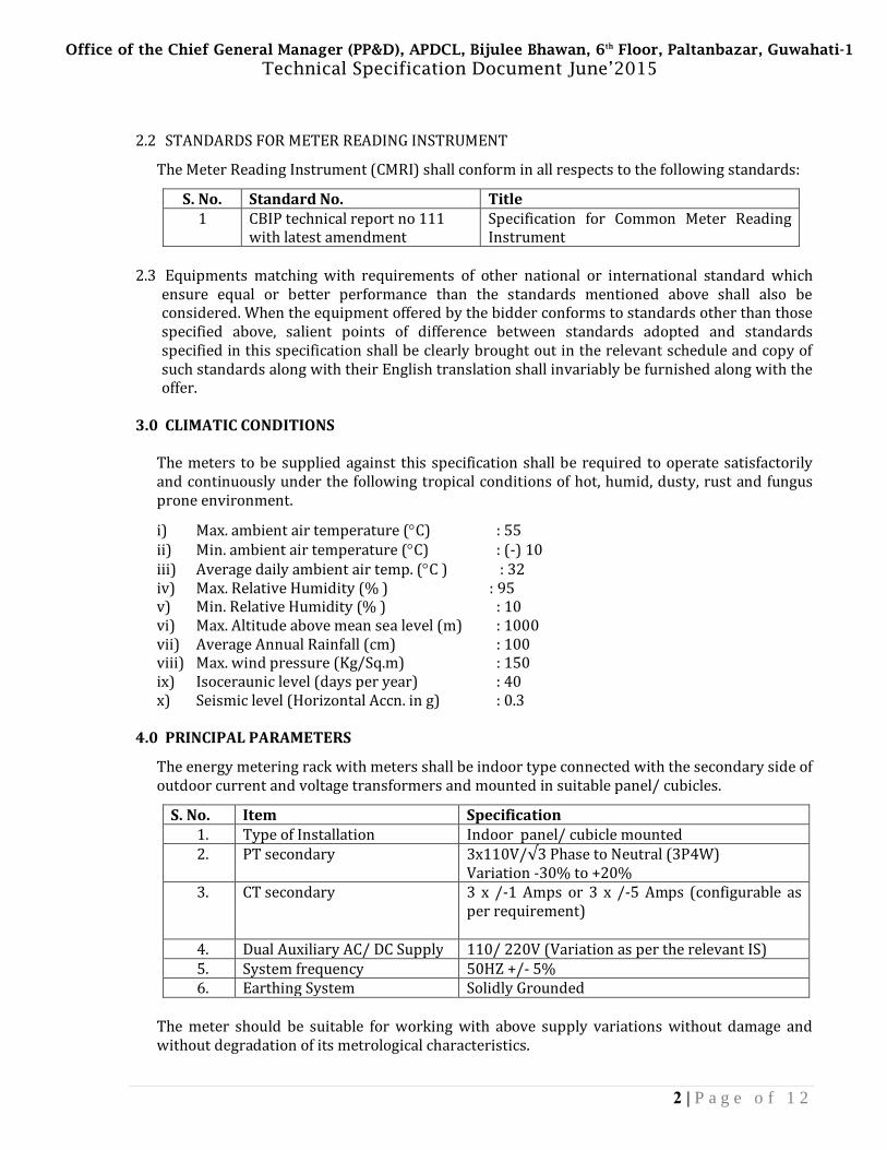
2.2 STANDARDS FOR METER READING INSTRUMENT
The Meter Reading Instrument (CMRI) shall conform in all respects to the following standards:
S. No. Standard No. Title 1 CBIP technical report no 111
with latest amendment Specification for Common Meter Reading Instrument
2.3 Equipments matching with requirements of other national or international standard which
ensure equal or better performance than the standards mentioned above shall also be considered. When the equipment offered by the bidder conforms to standards other than those specified above, salient points of difference between standards adopted and standards specified in this specification shall be clearly brought out in the relevant schedule and copy of such standards along with their English translation shall invariably be furnished along with the offer.
3.0 CLIMATIC CONDITIONS
The meters to be supplied against this specification shall be required to operate satisfactorily and continuously under the following tropical conditions of hot, humid, dusty, rust and fungus prone environment.
i) Max. ambient air temperature (°C) : 55 ii) Min. ambient air temperature (°C) : (-) 10 iii) Average daily ambient air temp. (°C ) : 32 iv) Max. Relative Humidity (% ) : 95 v) Min. Relative Humidity (% ) : 10 vi) Max. Altitude above mean sea level (m) : 1000 vii) Average Annual Rainfall (cm) : 100 viii) Max. wind pressure (Kg/Sq.m) : 150 ix) Isoceraunic level (days per year) : 40 x) Seismic level (Horizontal Accn. in g) : 0.3
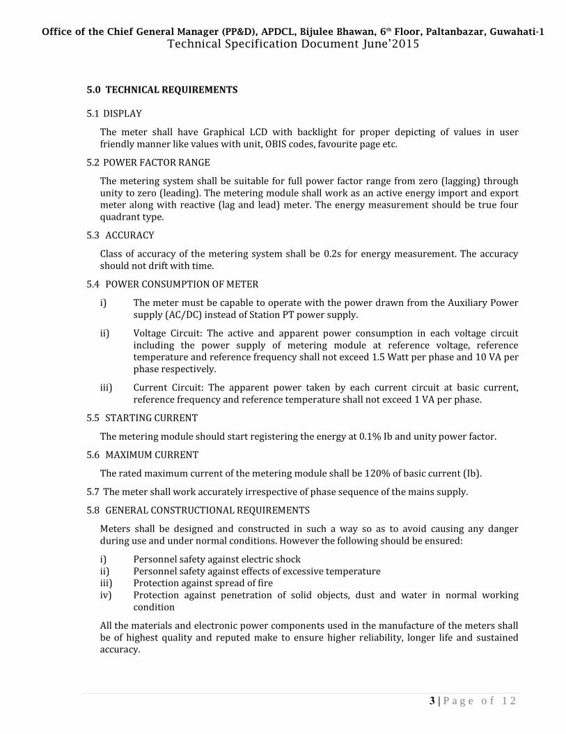
4.0 PRINCIPAL PARAMETERS
The energy metering rack with meters shall be indoor type connected with the secondary side of outdoor current and voltage transformers and mounted in suitable panel/ cubicles.
S. No. Item Specification 1. Type of Installation Indoor panel/ cubicle mounted 2. PT secondary 3x110V/√3PhasetoNeutral(3P4W)
Variation -30% to +20% 3. CT secondary 3 x /-1 Amps or 3 x /-5 Amps (configurable as
per requirement)
4. Dual Auxiliary AC/ DC Supply 110/ 220V (Variation as per the relevant IS) 5. System frequency 50HZ +/- 5% 6. Earthing System Solidly Grounded
The meter should be suitable for working with above supply variations without damage and without degradation of its metrological characteristics.
Office of the Chief General Manager (PP&D), APDCL, Bijulee Bhawan, 6th Floor, Paltanbazar, Guwahati-1 Technical Specification Document June’2015
3 | P a g e o f 1 2
5.0 TECHNICAL REQUIREMENTS
5.1 DISPLAY
The meter shall have Graphical LCD with backlight for proper depicting of values in user friendly manner like values with unit, OBIS codes, favourite page etc.
5.2 POWER FACTOR RANGE
The metering system shall be suitable for full power factor range from zero (lagging) through unity to zero (leading). The metering module shall work as an active energy import and export meter along with reactive (lag and lead) meter. The energy measurement should be true four quadrant type.
5.3 ACCURACY
Class of accuracy of the metering system shall be 0.2s for energy measurement. The accuracy should not drift with time.
5.4 POWER CONSUMPTION OF METER
i) The meter must be capable to operate with the power drawn from the Auxiliary Power supply (AC/DC) instead of Station PT power supply.
ii) Voltage Circuit: The active and apparent power consumption in each voltage circuit including the power supply of metering module at reference voltage, reference temperature and reference frequency shall not exceed 1.5 Watt per phase and 10 VA per phase respectively.
iii) Current Circuit: The apparent power taken by each current circuit at basic current, reference frequency and reference temperature shall not exceed 1 VA per phase.
5.5 STARTING CURRENT
The metering module should start registering the energy at 0.1% Ib and unity power factor.
5.6 MAXIMUM CURRENT
The rated maximum current of the metering module shall be 120% of basic current (Ib).
5.7 The meter shall work accurately irrespective of phase sequence of the mains supply.
5.8 GENERAL CONSTRUCTIONAL REQUIREMENTS
Meters shall be designed and constructed in such a way so as to avoid causing any danger during use and under normal conditions. However the following should be ensured:
i) Personnel safety against electric shock ii) Personnel safety against effects of excessive temperature iii) Protection against spread of fire iv) Protection against penetration of solid objects, dust and water in normal working
condition
All the materials and electronic power components used in the manufacture of the meters shall be of highest quality and reputed make to ensure higher reliability, longer life and sustained accuracy.
Office of the Chief General Manager (PP&D), APDCL, Bijulee Bhawan, 6th Floor, Paltanbazar, Guwahati-1 Technical Specification Document June’2015
4 | P a g e o f 1 2
The meters shall be designed with application specific integrated circuits. The electronic components shall be mounted on the printed circuit board using latest Surface Mount Technology (SMT).
All insulating materials used in the construction of meters shall be non-hygroscopic, non-aging and of tested quality. All parts that are likely to develop corrosion shall be effectively protected against corrosion by providing suitable protective coating.
The metering system when mounted in panel shall conform to the degree of protection IP53 in the normal working condition of IS 12063/ IEC 529 for protection against ingress of dust and moisture.
5.9 MANUFACTURING ACTIVITIES
Meter should be manufactured using SMT (Surface Mount Technology) components and by deploying automatic SMT pick and place machine and reflow solder process; the Bidder should own such facilities.
Quality should be ensured at the following stages:
i) At PCB manufacturing stage, each board shall be subjected to computerized bare board testing.
ii) At insertion stage all components should under go computerized testing for conforming to design parameters and orientation.
iii) Complete assembled and soldered PCB should under go functional testing using Automatic Test Equipment.
iv) Prior to final testing and calibration, all meters shall be subjected to accelerated ageing test to eliminate infant morality.
v) The calibration of meters shall be done in-house.
5.10 SEALING
Proper sealing arrangement shall be provided in metering system as follows:
i) Two numbers sealing screws shall be provided on the front cover of metering module. ii) Provision shall be available to seal the back connections on the metering rack using the
back plate. iii) Provision shall be available to seal optical port. iv) Meter must be ultrasonically sealed between base and cover of the meter.
The sealing arrangement should be suitable for application of Polycarbonate seals.
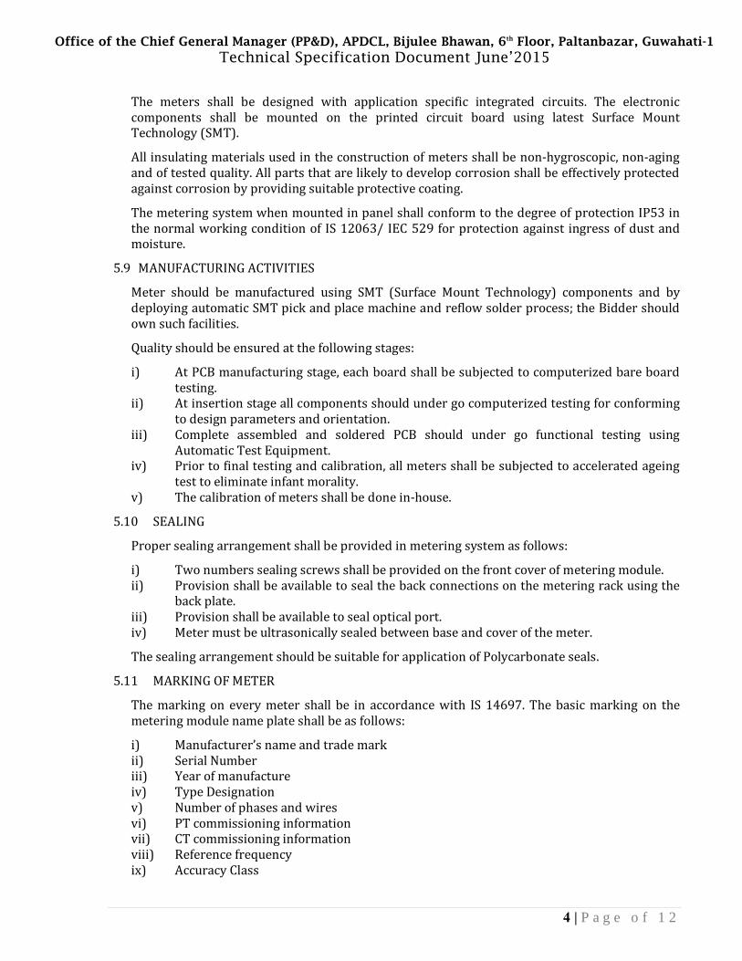
5.11 MARKING OF METER
The marking on every meter shall be in accordance with IS 14697. The basic marking on the metering module name plate shall be as follows:
i) Manufacturer’s name and trade mark ii) Serial Number iii) Year of manufacture iv) Type Designation v) Number of phases and wires vi) PT commissioning information vii) CT commissioning information viii) Reference frequency ix) Accuracy Class
Office of the Chief General Manager (PP&D), APDCL, Bijulee Bhawan, 6th Floor, Paltanbazar, Guwahati-1 Technical Specification Document June’2015
5 | P a g e o f 1 2
Additionally, following information shall also be available on name plate. i) Property Of “Purchaser name” ii) P.O. No. “Number”
5.11 The connection diagram of the connecting 3P4W meter shall be depicted via suitable sticker pasted on meter. The meter terminals shall be properly marked to identify voltage, Current, Auxiliary and communication ports.
5.12 The meters shall be suitable for being connected directly through its terminals to PTs having a rated secondary line- to- line voltage of 110 V and to CTs having a rated secondary current of 1A or 5A. Any further transformers/ transducers required for their functioning shall be in-built in the meters. Necessary isolation and/or suppression shall also be built-in, for protecting the meters from surges and voltage spikes that occur in the PT and CT circuits of extra high voltage switchyards.
5.13 The active energy measurement shall be carried out on 3 phase, 4 wire principle with an accuracy as per class 0.2s of IS14697. The meters shall compute the active energy and load import; active energy and load export from the substation bus bars during each successive 15 minute integration period block and store it in its non volatile memory.
5.14 The meter shall compute the average frequency during each successive 15 minute block and store in its memory.
5.15 The meter shall have Inputs/ Outputs pulsing pins availability. This shall help in transferring the same Energy parameters being recorded inside the meters on pulse output as well for SCADA application at remote distance.
5.16 The meter shall compute the reactive power on 3-phase, 4-wire principle, with an accuracy as per relevant IS/ IEC standards, and integrate the reactive energy algebraically into two separate reactive energy registers, one for the period for which the average RMS voltage is greater than 103% (Reactive High), and the other for the period for which the average RMS voltage is below 97.0% (Reactive Low). When lagging reactive power is being sent out from substations bus bars, reactive registers shall move forward. When reactive power flow is in the reverse direction, reactive registers shall move backwards.
5.17 Further, the reactive energy shall also be available in four different registers as- i) Reactive import while active import ii) Reactive import while active export iii) Reactive export while active import iv) Reactive export while active export.
5.18 Active and Apparent energies shall also be made available by meter in separate energy registers as –
i) Active energy Import ii) Active energy Export iii) Apparent energy (while active import) iv) Apparent energy (while active export)
5.19 Meter shall have provision to compute apparent energy based on lag only or lag+lead. The same shall be configured at factory end.
5.20 The meters shall be compatible with ABT tariff as well as TOD tariff.
5.21 For reactive power and reactive energy measurement, limits of errors of all the four quadrants shall be in accordance to IEC 62053-23/ IS14697.

Office of the Chief General Manager (PP&D), APDCL, Bijulee Bhawan, 6th Floor, Paltanbazar, Guwahati-1 Technical Specification Document June’2015
6 | P a g e o f 1 2
5.22 Each meter shall have a calibration LED (visual) for checking the accuracy of active energy measurement. Further, it shall be possible to switch over the same test output device to reactive energy via suitable means provided on the metering system. This LED shall be visible from the front side.
5.23 The metering system shall normally operate with the power drawn through the auxiliary AC or DC supply. The metering system design should enable the auxiliary supply to be switched automatically between the AC and DC voltage, depending upon their availability. Typical auxiliary voltages available are 110V AC and 110/ 220V DC. The system shall continue to work even if any one of the above auxiliary supply (AC/ DC) is present.
5.24 Each metering module shall have a built-in calendar and clock, having an accuracy of + 3 (three) minute per year or better. The calendar and clock shall be correctly set at the manufacturer’s works. The uncertainty of setting initial time shall not be more than + 30 seconds from Indian Standard Time as maintained by NPL New Delhi.
An automatic backup for continued operation of the meter’s calendar-clock shall be provided through a long life battery, which shall be capable of supplying the required power for at least two years under meter un-powered conditions. The meters shall be supplied duly fitted with the batteries, which shall not require to be changed for at least ten years, as long as total supply interruption does not exceed two years.
5.25 TOD (Time of day registers): The meter shall have TOD registers for active energy import and export, apparent energy import and export and apparent MD import and export. Maximum eight time of day registers including universal (0-24 hrs) register can be defined. It shall be possible to program number of TOD registers and TOD timings through suitable high level software/ MRI as an authenticated transaction.
5.26 Maximum Demand (MD) Registration: The meter shall continuously monitor and calculate the average demand of configured parameter during the integration period set and the maximum, out of these shall be stored along with date and time when it occurred in the meter memory. The maximum demand shall be computed on fixed block principle. The maximum registered value shall be made available in meter readings. The integration period shall be set as 15 minutes that shall be capable to change to other integration period (30/ 60 minutes), if required, through suitable high level software/ MRI as an authenticated transaction.
5.27 Maximum Demand Reset: Following provisions shall be available for MD reset in meter –
i) Auto billing at predefined date and time ii) Manual via common MD reset button (optional) iii) Authenticated transaction through suitable high level software/ MRI (optional)
5.28 The display shall be of Graphical LCD type with colored back-lit and soft push button. Individual display shall be provided for all the meters housed in a metering rack.
The display shall indicate direct values (i.e. without having to apply any multiplying factor) of measured/ computed parameters as per the meter commissioning. It should be possible to easily identify the single or multiple displayed parameters through legends on the metering system display like OBIS codes etc.
The register shall be able to record and display starting from zero, for a minimum of 1500 hours, the energy corresponding to rated maximum current at reference voltage and unity power factor. The register shall not roll over in between this duration.
Office of the Chief General Manager (PP&D), APDCL, Bijulee Bhawan, 6th Floor, Paltanbazar, Guwahati-1 Technical Specification Document June’2015
7 | P a g e o f 1 2
5.29 Each of the metering module shall display on demand & in Auto scroll mode the following quantities/ parameters:
i) LCD segment check ii) Date iii) Time iv) Voltage (Vr,Vy,Vb) v) Current (Ir,Iy,Ib) vi) Three Phase Power Factor vii) Cumulative active energy import viii) Cumulative active energy export ix) Cumulative net active (Import – Export) energy x) Cumulative reactive energy lag while active import xi) Cumulative reactive energy lead while active import xii) Cumulative reactive energy lag while active export xiii) Cumulative reactive energy lead while active export xiv) Cumulative apparent energy (while active import) xv) Cumulative apparent energy (while active export) xvi) Cumulative Reactive High energy xvii) Cumulative Reactive Low energy xviii) Last 15 minutes block average of active import energy xix) Last 15 minutes block average of active export energy xx) Last 15 minutes block average of the net active (Import – Export) energy xxi) Last 15 minutes block average frequency xxii) MD reset count xxiii) Maximum demand apparent (while active import) for current month (0-24 hrs) xxiv) Maximum demand apparent (while active export) for current month (0-24 hrs) xxv) Cumulative active import energy reading of predefined date and time for monthly billing
purpose xxvi) Cumulative active export energy reading of predefined date and time for monthly billing
purpose xxvii) Cumulative net active (Import – Export) energy reading of predefined date and time for
billing purpose xxviii) Cumulative apparent energy (while active import) reading of predefined date and time
for monthly billing purpose xxix) Cumulative apparent energy (while active export) reading of predefined date and time
for monthly billing purpose xxx) Maximum demand for apparent (while active import) of predefined date and time for
monthly billing purpose xxxi) Maximum demand for apparent (while active export) of predefined date and time for
monthly billing purpose xxxii) Present tamper status xxxiii) Date of first occurrence of tamper xxxiv) Time of first occurrence of tamper xxxv) Time of last restoration of tamper xxxvi) Date of last restoration of tamper xxxvii) Total tamper count
There should be a facility to configure the display parameters in favorite pages.
Office of the Chief General Manager (PP&D), APDCL, Bijulee Bhawan, 6th Floor, Paltanbazar, Guwahati-1 Technical Specification Document June’2015
8 | P a g e o f 1 2
5.30 Load Survey: Each metering module shall have a non-volatile memory in which the following shall be automatically stored for each successive fifteen (15) minute block:
i) Active import ii) Active export iii) Average frequency iv) Apparent while active import v) Apparent while active export vi) Reactive High energy (V>103%) vii) Reactive Low energy (V<97%)
15-minute average of the above parameters shall be available for minimum last thirty five (35) days. Meter memory is required for 35days minimum so that data for one calendar month can be downloaded at a time. It shall be possible to select either energy or demand view at Base Computer Software (BCS) end. The load survey data should be available in the form of bar charts as well as in spreadsheets. The BCS shall have the facility to give complete time synchronized load survey data both in numeric and graphic form.
5.31 Billing parameters: The predefined date and time for registering the billing parameters of shall be 00.00 hours of the first day of each calendar (billing) month. Each meter shall store the following parameters corresponding to defined bill dates for up to last six (6) months:
i) Active energy import ii) Active energy export iii) Apparent energy (while active import) iv) Apparent energy (while active export) v) Maximum demand Apparent (while active import) vi) Maximum demand Apparent (while active export)
5.32 Daily midnight parameters: The metering modules shall store following end day parameters for last thirty five (35) days:
i) Active energy import ii) Active energy export iii) Reactive high energy iv) Reactive low energy
5.33 Data Communication Capability:
The metering system should have a suitable communication ports for local reading, remote and on-line communication facilities.
Each metering module shall have an optical galvanically isolated serial communication (in the form of 1107 port) & USB port on its front for tapping all the data stored in its memory. Meter reading instrument (MRI) shall be used for the purpose of local meter reading via this optical communication port and Pen drive for USB port. MRI shall serve as the interface between meters and PC loaded with Base Computer Software. It shall also be possible to download meter data via this port by connecting laptop computer directly. The overall intention is to have the local ports is to tap the data stored in meter once in a week/month and transmit the same to PC with BCS for view.
The metering system shall further provide a serial RS232, RS485 and Ethernet communication port for remote data transfer to a central location. This port shall be capable of data transfer to a remote computer over suitable communication media (GPRS/VSAT/ Leased line/ OFC) using
Office of the Chief General Manager (PP&D), APDCL, Bijulee Bhawan, 6th Floor, Paltanbazar, Guwahati-1 Technical Specification Document June’2015
9 | P a g e o f 1 2
suitable communication hardware (modems/ multiplexer/ communication cables etc.) as required for proper functioning of remote meter reading scheme.
5.34 Each meter shall have a unique identification code i.e. serial number, which shall be marked on name plate as well as in its memory. Further all meters of the same model shall be totally identical in all respects except for their unique identification codes.
5.35 The meters shall safely withstand the usual fluctuations arising during faults etc. In particular, 115% of rated PT secondary voltage applied continuously and 190% of rated voltage applied for 3.0 seconds, and 20 times of rated CT secondary current applied for 0.5 seconds shall not cause any damage to or malfunctioning of the meters. Further the immunity of metering system to external magnetic field shall be as per latest CBIP recommendations.
5.36 Each meter shall have a non volatile memory in which the parameters as mentioned in this specification shall be stored. The non volatile memory shall retain the data for a period not less than 10 years under un-powered condition; battery back up memory shall not be treated as NVM.
5.37 Meter shall have the capability and facility to compensate for errors of external measurement transformers i.e. CT and PT:
i. Linear compensation for measurement PT errors (ratio and phase); there shall be linear adjustment which shall be applied across the complete measurement range of the transformer.
ii. Non-linear compensation for measurement CT errors (ratio and phase) compensation; this shall allow multiple ratio and phase adjustments to be applied for different load points per phase input of the meter.
It should be possible to program the errors of CT and PT in meter through front optical communication port using compatible high level software. Metering system design should support this feature and further it shall be possible to configure & incorporate this feature in meter at later stage whenever required.
5.38 The metering modules shall be draw out type with automatic CT shorting feature so as to ease the testing/ replacement of meters without disturbing the system.
5.39 The meter display should depict the total harmonic distortion (THD) of current and voltages up to 31st level of power quantity for providing the feature of supply monitoring to Utility.
6.0 TAMPER DETECTION FEATURES
6.1 The meter shall have features to detect and log the occurrence and restoration of following tampers, along with date and time of event:
i) Phase wise Missing Potential – The meter shall detect missing potential (1 or 2 phases) provided the line current is above a specified threshold. The voltage at that stage would be below a specified threshold.
ii) Phase wise Current Circuit Reversal – The meter shall detect reversal of polarity provided the current terminals are reversed. This shall be recorded for 1 or 2 phase CT reversal.
iii) Voltage Unbalance – The meter shall detect voltage unbalance if there is unbalance in voltages.

Office of the Chief General Manager (PP&D), APDCL, Bijulee Bhawan, 6th Floor, Paltanbazar, Guwahati-1 Technical Specification Document June’2015
10 | P a g e o f 1 2
iv) Current Unbalance – The meter shall detect current unbalance if there is unbalance in load conditions. Meter should ensure true system conditions before going for current unbalance checks.
v) CT Miss – The meter shall detect current miss if the current is below a defined threshold, provided the phase voltage is above a specified threshold.
vi) Non rollover events like the “Meter Cover Open” tamper. vii) Influence of permanent magnet or ac/dc electromagnet. viii) Neutral disturbance
Snapshots of phase wise voltage, phase wise active current and phase wise power factor shall be provided with above specified tamper events.
Further, each meter module shall record the following events along with total duration:
i) Power On/Off – The meter shall detect power off if both the auxiliary supplies fail. The event shall be recorded on the next power up. At the same time power on event shall be recorded. No snapshot shall be logged with this event.
ii) Feeder Supply Fail -This event shall be logged when feeder supply, i.e. all the voltages goes below certain threshold. No snapshot shall be logged with this event.
6.2 Last two hundred (200) events (occurrence + restoration), in total, shall be stored in the meter memory on first in first out basis.
6.3 There shall be five separate compartments for logging of different type of tampers:
Compartment No.1 50 events of Missing Potential Compartment No.2 50 events of CT Reversal Compartment No.3 25 events for Power Failure / Power On-Off Compartment No.4 75 events of Transaction related and other tampers as per IS:15959
Category B
Once one or more compartments have become full, the last tamper event pertaining to the same compartment shall be entered and the earliest (first one) tamper event should disappear. Thus, in this manner each succeeding tamper event shall replace the earliest recorded event, compartment wise. Events of one compartment/ category should overwrite the events of their own compartment/ category only. In general persistence time of 5 min. for occurrence and restoration respectively need to be supported in meter.
6.4 Tamper count should increase as per occurrence (not restoration) of tamper events. Total no. of counts shall be provided on BCS.
7.0 TRANSACTIONS The meter shall record critical events (as performed in authenticated manner) of Time set, MD reset operation and tariff change. These events shall be logged in roll over mode for up to twenty numbers.
8.0 SELF DIAGNOSTIC FEATURE
The meter shall be capable of performing complete self diagnostic check to monitor the circuits for any malfunctioning to ensure integrity of data in memory location all the time. The meter shall have indications for unsatisfactory/ nonfunctioning/ malfunctioning of the following:
i) Non volatile memory ii) RTC battery
Office of the Chief General Manager (PP&D), APDCL, Bijulee Bhawan, 6th Floor, Paltanbazar, Guwahati-1 Technical Specification Document June’2015
11 | P a g e o f 1 2
The above malfunctioning should be flagged in the meter memory and should be made available in meter reading data.
9.0 TYPE TEST CERTIFICATES
The meters shall be fully type tested as per relevant standards IS 14697. The type test report of the meters shall be submitted by bidder along with the offer. Type test reports shall not be more than 2 years old.
Office of the Chief General Manager (PP&D), APDCL, Bijulee Bhawan, 6th Floor, Paltanbazar, Guwahati-1 Technical Specification Document June’2015
12 | P a g e o f 1 2
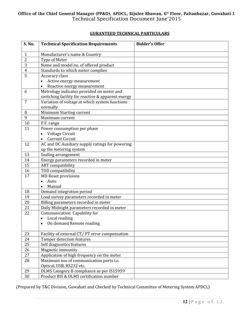
GURANTEED TECHNICAL PARTICULARS
S. No. Technical Specification Requirements Bidder’s Offer
1 Manufacturer's name & Country 2 Type of Meter 3 Name and model no. of offered product 4 Standards to which meter complies 5 Accuracy class
• Active energy measurement • Reactive energy measurement
6 Metrology indicator provided on meter and switching facility for reactive & apparent energy
7 Variation of voltage at which system functions normally
8 Minimum Starting current 9 Maximum current 10 P.F. range 11 Power consumption per phase
• Voltage Circuit • Current Circuit
12 AC and DC Auxiliary supply ratings for powering up the metering system
13 Sealing arrangement 14 Energy parameters recorded in meter 15 ABT compatibility 16 TOD compatibility 17 MD Reset provisions
• Auto • Manual
18 Demand integration period 19 Load survey parameters recorded in meter 20 Billing parameters recorded in meter 21 Daily Midnight parameters recorded in meter 22 Communication Capability for
• Local reading • On demand Remote reading
23 Facility of external CT/ PT error compensation 24 Tamper detection features 25 Self diagnostics features 26 Magnetic immunity 27 Application of high frequency on the meter 28 Maximum nos of communication ports i.e.
Optical, USB, RS232 etc.
29 DLMS Category B compliance as per IS15959 30 Product BIS & DLMS certification number
(Prepared by T&C Division, Guwahati and Checked by Technical Committee of Metering System APDCL)


![BouncingBallExperimentLab...Table1 ExperimentalMeasurements,RegularPingPongDrop Method1 Rebound1[ 1in] Method1 Rebound2[ 1in] Method2 Bounce1[ 0.2s] Method2 Bounce2[ 0.2s] Method3](https://static.fdocuments.in/doc/165x107/60baed3714376f48c45eb536/bouncingballexperimentlab-table1-experimentalmeasurementsregularpingpongdrop.jpg)


