TECHNICAL SPECIFICATIONS - dhhl.hawaii.gov
128
STATE OF HAWAII DEPARTMENT OF HAWAIIAN HOME LANDS 91-5420 Kapolei Parkway, Kapolei, HI. 96707 TECHNICAL SPECIFICATIONS FOR FURNISHING LABOR AND MATERIALS FOR Kau Water System Improvements – Phase 1 Kamaoa, Kau, Island of Hawaii, Hawaii TMK: (3) 9-3-001:002; (3) 9-3-002:005, 030; (3) 9-3-003:013, 025 IFB No.: IFB-20-HHL-025 April 2020
Transcript of TECHNICAL SPECIFICATIONS - dhhl.hawaii.gov
STATE OF HAWAII DEPARTMENT OF HAWAIIAN HOME LANDS
91-5420 Kapolei Parkway, Kapolei, HI. 96707
TECHNICAL SPECIFICATIONSFOR
FURNISHING LABOR AND MATERIALS FOR
Kau Water System Improvements – Phase 1Kamaoa, Kau, Island of Hawaii, Hawaii
TMK: (3) 9-3-001:002; (3) 9-3-002:005, 030; (3) 9-3-003:013, 025
IFB No.: IFB-20-HHL-025
April 2020

INDEX TO TECHNICAL SPECIFICATIONS
Kau Water System i Index to Technical SpecsImprovements – Phase 1 IFB-20-HHL-025
TECHNICAL SPECIFICATIONS
DIVISION 1 - GENERAL REQUIREMENTSSECTION 01010 – MOBILIZATION AND DEMOBILIZATION.....................................3
DIVISION 2 – SITE WORKSECTION 02010 – GENERAL REQUIREMENTS FOR CIVIL WORK........................4SECTION 02050 – DEMOLITION AND REMOVAL WORK ........................................4SECTION 02110 – CLEARING AND GRUBBING.......................................................2SECTION 02200 – EARTHWORK.............................................................................12SECTION 02362 – SOIL TREATMENT FOR VEGETATION CONTROL ...................1SECTION 02510 – ASPHALTIC CONCRETE PAVEMENT........................................5SECTION 02665 – WATER SYSTEM .......................................................................12
DIVISION 3 – CONCRETESECTION 03200 – CONCRETE REINFORCING........................................................4SECTION 03210 – EARTHQUAKE CABLES..............................................................3SECTION 03300 – CAST-IN-PLACE CONCRETE ...................................................19
DIVISION 4 – MASONRY (NOT USED)
DIVISION 5 – METALSSECTION 05500 – MISCELLANEOUS METALS FABRICATION.............................10SECTION 05600 – ALUMINUM STAIRS.....................................................................4
DIVISION 6 – WOOD AND PLASTICSSECTION 06600 – FIBERGLASS REINFORCED POLYMER (FRP) PRODUCTS
AND FABRICATION................................................................................4
DIVISION 7 – THERMAL AND MOISTURE PROTECTION (NOT USED)
DIVISION 8 – DOORS, WINDOWS, GLASSSECTION 08900 – LOUVERS AND VENTS ...............................................................4
DIVISION 9 – FINISHESSECTION 09900 – RESERVOIR PAINTING...............................................................5
DIVISION 10 – SPECIALTIES (NOT USED)
DIVISION 11 – EQUIPMENT (NOT USED)
DIVISION 12 – FURNISHINGS (NOT USED)
INDEX TO TECHNICAL SPECIFICATIONS
Kau Water System ii Index to Technical SpecsImprovements – Phase 1 IFB-20-HHL-025
DIVISION 13 – SPECIAL CONSTRUCTIONSECTION 13600 – RESERVOIR EXPANSION AND CONSTRUCTION JOINTS ......4SECTION 13700 – RESERVOIR WALL, BASE, AND TOP JOINTS...........................3
DIVISION 14 – CONVEYING SYSTEMS (NOT USED)
DIVISION 15 – MECHANICAL (NOT USED)
DIVISION 16 – ELECTRICALSECTION 16050 – BASIC MATERIALS AND METHODS ........................................12SECTION 16100 – SUPERVISORY CONTROL AND DATA ACQUISITION (SCADA)
SYSTEM ..................................................................................................10

IFB-20-HHL-025 Mobilization and Demobilization Kau Water System Improvements-Phase 1 01010-1
DIVISION 1 – GENERAL REQUIREMENTS SECTION 01010 – MOBILIZATION AND DEMOBILIZATION PART 1 – GENERAL MOBILIZATION 1.01 DESCRIPTION Mobilization includes preparatory work and operations necessary for:
A. Movement of personnel, equipment, and supplies to the project site.
B. Acquisition of falsework materials.
C. Establishment of offices, buildings, and other facilities excluding the field office, necessary for work on the project.
D. Costs incurred on operations that must be performed before starting
work on the various items on the project site. E. Performance and payment bond premiums for contract work excluding
force account items, allowances, and extra work amount. 1.02 MATERIAL
None specified.
1.03 APPLICABILITY
A. Maximum bid allowed for this item is an amount not to exceed six (6)
percent of the sum of all items excluding the bid price of this item, field office, allowances, force account items, design submittal and end of job submittal items.
B. The Department will reduce indicated amount to allowable maximum if
proposal shows an amount over allowable maximum. The Department will adjust "Sum of Contract Items" to reflect such reduction. The Department will use "Sum of Contract Items" adjusted as if bidder submitted its proposal in amounts as reduced and adjusted.
1.04 MEASUREMENT
Mobilization will be paid on a lump sum basis. Measurement for payment will not apply.
IFB-20-HHL-025 Mobilization and Demobilization Kau Water System Improvements-Phase 1 01010-2
1.05 PAYMENT
A. The Department will pay for accepted mobilization on a contract lump sum basis. Payment will be full compensation for work prescribed in this section and contract documents.
B. The Department will pay for following pay item when included in proposal
schedule:
Pay Item Pay Unit Mobilization (Not to exceed 6% of sum of all items excluding bid price of this item, field office, allowances, force account items, design submittal and end of job submittal items. Lump Sum The Department will make partial payments as follows:
A. Pay 10 percent of amount bid for mobilization when earning 1 percent of original contract amount.
B. Pay 50 percent of amount bid for mobilization when earning 2.5 percent
of original contract amount.
C. Pay 75 percent of amount bid for mobilization when earning 5 percent of original contract amount.
D. Pay 100 percent of amount bid for mobilization when earning 10 percent
of original contract amount. PART 2 GENERAL DEMOBILIZATION 2.01 DESCRIPTION
The Contractor shall demobilize and transport his construction plant (includes concrete plant and test facility) and equipment including materials, supplies and temporary buildings off the site as soon as possible after construction is completed Demobilization shall include all cleanup required under this contract and as directed by the Department. The Contractor shall return the site to its original condition or better. Demobilization and final cleanup shall be completed prior to final acceptance.
IFB-20-HHL-025 Mobilization and Demobilization Kau Water System Improvements-Phase 1 01010-3
2.02 MEASUREMENT
Demobilization shall be considered incidental to the scope of work under this contract and therefore covered under the terms of this contract. No separate payment shall be made.
END OF SECTION
IFB-20-HHL-025 General Requirements for Civil Work Kau Water System Improvements-Phase 1 02010-1
DIVISION 2 – CIVIL WORK
SECTION 02010 – GENERAL REQUIREMENTS FOR CIVIL WORK
PART 1 – GENERAL
1.01 GENERAL CONDITIONS
The General Provisions and Special Provisions in these specifications shall govern all work specified hereinafter in all DIVISIONS and SECTIONS.
1.02 DIVISION OF WORK
The Divisions and Sections into which these specifications are divided shall not be considered an accurate or complete segregation of work by trades. This also applies to all work specified within each section.
1.03 SCOPE OF WORK
The work required to be performed by the Contractor consists of constructing and completing the project “Kau Water System Improvements – Phase 1” at the Department of Hawaiian Home Lands at Kau, in accordance with the Drawings and Specifications and all applicable provisions of the Contract Documents.
1.04 DRAWINGS
A. The location, extent and design of the required construction and improvements are shown and noted on the Drawings accompanying these Specifications, which Drawings are hereby made a part of these Specifications and the Contract. A complete list of Drawings and Titles is given on the Title Sheet of the Drawings.
B. Where “as shown”, “as indicated”, “as noted”, “as detailed”, “as scheduled”, or
words of like meaning are used in these Contract Documents, it shall be understood that the reference to the foregoing Drawings is being made, unless otherwise specified.
C. When reference to the work “plans” is made anywhere in the Contract
Documents, it shall be understood that such reference refers to the Drawings.
1.05 SPECIFICATION LANGUAGE
These Specifications are written in imperative and abbreviated form. This imperative language of the technical sections is directed at the Contractor, unless specifically noted otherwise. Incomplete sentences shall be completed by inserting “shall”, “the Contractor shall”, and “shall be”, and similar mandatory phrases by inference in the same manner as they are applied to notes on the drawings. The words “shall be” shall be supplied by inference where a colon (:) is used within sentences or phrases. Except as worded to the contrary, fulfill (perform) all indicated requirements whether stated imperatively or otherwise.
IFB-20-HHL-025 General Requirements for Civil Work Kau Water System Improvements-Phase 1 02010-2
1.06 SUBSTITUTION OF MATERIALS AND EQUIPMENT
A. Request for substitution shall be submitted within the time designated in the SPECIAL PROVISIONS.
B. All submittals, excepting for samples and documents requiring original signature, shall be e-mailed to Sara T. Okuda at the Department of Hawaiian Home Lands Office at E-Mail: [email protected]. The “Subject of e-mail request shall begin with the IFB number. Samples and documents requiring original signature shall be mailed or delivered to the Land Development Division Office, Department of Hawaiian Home Lands, 91-5420 Kapolei Parkway, Kapolei, HI 96707.
C. E-mailed request shall be submitted together with electronic technical
brochures and be accompanied by a statement of variances as shown on the attached “Sample Request for Substitution.” Only “Request for Substitution” using the attached sample format will be considered.
The statement of variances shall list all features of the proposed substitution which differ from the plans, specifications and/or product(s) specified and shall further certify that the substitute has no other variant features. The brochures shall be clearly marked showing make, model, size, options, etc., and shall include sufficient evidence to enable the Department to evaluate each feature listed as a variance. All submittal with insufficient information for evaluation shall be rejected. Should an unlisted variance be discovered after installation of the product, the penalty shall be immediate replacement with the original specified item at no cost to the Department. If sufficient evidence from which a determination can be made for a particular model does not accompany a request for substitution, the request shall be denied. The decision of the Department will be final.
D. When submitting request for substitutions, if the Contractor elects to use
materials and/or equipment other than those shown on the plans and/or specifications, the Contractor shall be responsible to revise existing conditions and to coordinate work with other trades as many be necessary because of the substituted product. Any additional cost to implement such a change shall be borne by the Contractor at no cost to the Department.
E. Bidders are cautioned to review the Technical Specifications carefully and
thoroughly. Objections to or request for clarification of the specifications shall be made in writing to Sara T. Okuda at the Department of Hawaiian Home Lands Office at E-Mail: [email protected], no later than fourteen (14) consecutive calendar days prior to the scheduled bid opening date. The submittal of a bid shall be considered as acceptance of the specifications as published. The “Subject of e-mail request shall begin with the IFB number. Protest concerning the Technical Specifications lodged after bid opening shall not be considered.

IFB-20-HHL-025 General Requirements for Civil Work Kau Water System Improvements-Phase 1 02010-3
1.07 PATENTED DEVICES, MATERIALS AND PROCESSES: If the Contractor is required or desires to use any design, device, material or process covered by letters of patent or copyright, the right for such use shall be processed by the Contractor from the patentee or owner. The Contractor and Surety shall indemnify and hold harmless the State and its Departments and Agencies, and affected third party, Designer of Record (Architect/Engineer), or political subdivision from any and all claims for infringement by reason of the trademark or copyright in connection with the work to be performed under the contract, shall indemnify the State and its Department and Agencies, and Designer of Record (Architect/Engineer) for any costs, expenses and damages which it may be obligated to pay by reason of any infringement at any time during the prosecution of after the completion of the work.
1.08 DESCRIPTION OF BID ITEM
The work includes all labor, materials, tools, equipment necessary to complete the construction of the water system improvements at the location shown on the plans. Major work items include clearing and grubbing at the reservoir site and water filling station, 0.10-million gallon reservoir, grading, A.C. paving, facility piping, drainage improvements, electrical work, and incidental related work.
PART 2 – PRODUCTS Not used. PART 3 – EXECUTION Not used.

IFB-20-HHL-025 General Requirements for Civil Work Kau Water System Improvements-Phase 1 02010-4
S A M P L E
Date: ____________________
Department of Hawaiian Home Lands Land Development Division 91-5420 Kapolei Parkway Kapolei, Hawaii 96707 E-Mail: [email protected] To Whom It May Concern: Subject: REQUEST FOR SUBSTITUTION Project Title: ________________________________________________________ ________________________________________________________ ________________________________________________________ In accordance with the GENERAL REQUIREMENTS, I hereby submit for substitution with the technical brochures and statement of variances for your review and approval for the item(s) shown below: SECTION/SPECIFIED SUBSTITUTE OR VARIANT 3/ _ITEM_ _BRAND_ ALTERNATE BRAND FEATURES I further certify that my request for substitution of the above item(s) has no other variant features and complies with the plans and specifications for subject project. _______________________________ SIGNATURE NOTE: 1. Please use own letterhead. 2. Submit by E-Mail: [email protected] 3. If no variant feature, then indicate “None.”
END OF SECTION
IFB-20-HHL-025 Demolition and Removal Work Kau Water System Improvements-Phase 1 02050-1
SECTION 02050 –DEMOLITION AND REMOVAL WORK PART 1 – GENERAL 1.01 GENERAL CONDITIONS
As specified in Section 02010. 1.02 PERMIT AND FEES
The Contractor shall obtain and pay for all necessary permits for removal work prior to commencement of work.
1.03 WORK DESCRIPTION
The work to be performed under this section shall include the furnishing of all labor, tools, equipment and incidentals necessary to perform all demolition and removal work indicated on the drawings or required for the reception of the new construction specified. This includes, but is not limited to, demolition and removal of existing sidewalk, curb, gutter, guardrail, signs, drainage structures, and pavements, and demolition and removal required for any adjustment, extension or protection of existing utilities.
1.04 JOB CONDITIONS A. Condition of Existing Improvements: The Department assumes no
responsibility for the actual condition of items or portions of structures to be removed.
B. Interference with Adjacent Occupied Spaces: Maintain free and
safe passage to and from occupied spaces. Provide temporary barricades and other forms of protection as required to protect the general public from injury due to demolition and/or removal work.
C. Storage or sale of removed items on site will not be permitted. D. Protection: Provide temporary barricades and other forms of
protection as required to protect the general public from injury due to selective removal work and to maintain security.
1. Provide interior and exterior shoring, bracing, or support to
prevent movement, settlement, or collapse of structure or elements to be removed, and adjacent facilities or work to remain.
IFB-20-HHL-025 Demolition and Removal Work Kau Water System Improvements-Phase 1 02050-2
2. Protect from damage existing finish work that is to remain in place and becomes exposed during demolition operations.
3. Life safety procedures and provisions shall be in
conformance with all applicable Federal, State, and City and County regulations, including OSHA.
E. Damages: Promptly repair damages caused to adjacent facilities or
areas by removal work at no cost to the Department. F. Traffic: Conduct demolition operations and debris removal in a
manner to ensure minimum interference with roads, streets, walks, and other adjacent occupied or used facilities. Do not close, block or otherwise obstruct streets, walks or other occupied or used facilities without written permission from authorities having jurisdiction. Provide alternate routes around closed or obstructed traffic ways if required by governing regulations.
G. Use of explosives will not be permitted. H. Dust and Erosion Control: Contractor shall comply with
requirements set forth in Section 01567 – POLLUTION CONTROL. PART 2 – PRODUCTS
Not Used. PART 3 - EXECUTION 3.01 CONSTRUCTION REQUIREMENTS
The Contractor shall exercise every precaution to preserve and protect existing improvements to remain or to be removed by others.
3.02 EXISTING UTILITY LINES A. The existence of underground utility lines other than those shown is
not definitely known. The Contractor shall be responsible for toning, probing, obtaining as-built drawings, etc., to determine existing utility locations prior to any demolition work. The Contractor shall promptly repair all damaged utilities at no cost to the Department.
B. The Contractor shall serve proper notice and consult with the
Engineer regarding any temporary disconnections of electrical or other utility lines in the area which may be required for the removal
IFB-20-HHL-025 Demolition and Removal Work Kau Water System Improvements-Phase 1 02050-3
work, and all such lines where necessary shall be properly disconnected before commencing with the work.
3.03 DEMOLITION A. All work shall be executed as indicated on the plans, with due
consideration for all items to remain. B. Limits of asphalt concrete pavement removal shall be as shown on
the plans or as directed by the Engineer. Saw cut along the excavation line to provide clean and straight joint lines.
C. If required, removal of existing signs includes foundations below
grade. D. Any open trenches, holes, depressions and pits left open at the end
of the working day shall be covered by steel plates. E. If unanticipated mechanical, electrical or structural elements which
conflict with intended function or design are encountered, investigate and measure both nature and extent of the conflict. Submit report to Engineer in written, accurate detail. Pending receipt of directive from Engineer rearrange selective demolition schedule as necessary to continue overall job progress without delay.
3.04 DISPOSITION OF MATERIAL A. All materials resulting from removal work, except as indicated or
specified otherwise, shall become the property of the Contractor and shall be removed from the limits of Department property. Remove rubbish and debris from the jobsite daily, unless otherwise directed; do not allow accumulations inside or outside any buildings or roadways. The Contractor shall transport and legally dispose of materials off site. Remove and transport debris and rubbish in a manner that will prevent spillage on streets or adjacent areas.
B. If hazardous materials are encountered during demolition
operations, comply with applicable State, Federal and local regulations, laws, and ordinances concerning removal, handling, and protection against exposure or environmental pollution.
C. Burning of removed materials is not permitted on project site.
IFB-20-HHL-025 Demolition and Removal Work Kau Water System Improvements-Phase 1 02050-4
3.05 CLEAN-UP AND REPAIR A. Any disturbance to road beds, landscaped areas, brick pavers, etc.,
shall be restored to original condition. The Contractor shall take care to avoid damage to immediate and surrounding areas and protect property and vehicles.
B. In landscaped areas, remove grass in a manner that will allow
replacement close to its original condition. Use a drop cloth or similar ground cover at all times to contain and hold removal of earth and plantings, whether on concrete, asphalt, lawn, and/or landscaped areas.
C. Any concrete, asphalt, or brick pavers removed shall be replaced in
as close to original condition as possible, and within the limits of generally accepted trade standards. When regrassing is required, the grass used shall match the surrounding area.
D. Damage resulting from removal work shall be repaired by the
Contractor at his/her expense. The condition of all existing exposed surfaces shall be equal to or better than that which existed before the removal work. Where the method of repair work is not indicated or specified, the Contractor shall perform the repair work in accordance with the limits of generally accepted trade standards.
END OF SECTION

IFB-20-HHL-025 Clearing and Grubbing Kau Water System Improvements-Phase 1 02110-1
SECTION 02110 – CLEARING AND GRUBBING PART 1 - GENERAL 1.01 GENERAL CONDITIONS
As specified in Section 02010.
1.02 WORK DESCRIPTION
The work covered in this section shall consist of furnishing all labor, materials, equipment, tools and incidentals necessary for clearing and grubbing as shown on the plans and specified herein.
1.03 PERMITS AND FEES
The Contractor shall obtain and pay for all necessary permits required to perform this work.
PART 2 – PRODUCTS Not used. PART 3 - EXECUTION 3.01 PROTECTION OF ITEMS TO REMAIN
The Contractor shall continually maintain adequate protection of trees, shrubbery, topographic features and all other items indicated to remain.
3.02 CLEARING AND GRUBBING
A. The overall limits of the clearing and grubbing, as shown on the plans, shall be staked prior to construction.
B. The Contractor shall clear the area within the grading limits of all
vegetative material and obstructions necessary for the proper reception, construction, execution and completion of other work specified in this contract. Vegetative material includes trees, logs, stumps, roots of downed trees, brush, grass and weeds. Obstructions include buildings, lumber, fences, trash piles and other unwanted materials.
C. Within the grading limits and where indicated on the drawings, grub the
entire ground surface of all grass, weeds, stumps, roots and other objectionable materials down to at least 12 inches below the existing ground surface.
D. No excavation or filling shall be undertaken until area has been cleared
and grubbed.

IFB-20-HHL-025 Clearing and Grubbing Kau Water System Improvements-Phase 1 02110-2
E. The Contractor shall protect from injury and damage all surrounding
plants, pavements, buildings, utilities, etc., and shall leave all in as good a condition as at present. Any damage to existing improvements shall be repaired or replaced by the Contractor to the satisfaction of the Engineer.
3.03 DISPOSITION OF MATERIAL
A. All materials resulting from the clearing and grubbing work, shall be removed from the limits of Department property. Remove rubbish and debris from the jobsite daily, unless otherwise directed; do not allow accumulations inside or outside any buildings or roadways. The Contractor shall transport and legally dispose of materials off site. Remove and transport debris and rubbish in a manner that will prevent spillage on streets or adjacent areas.
B. If hazardous materials are encountered during the clearing and grubbing
operations, comply with applicable State, Federal and local regulations, laws, and ordinances concerning removal, handling, and protection against exposure or environmental pollution.
C. Burning of removed materials is not permitted on the project site. 3.04 INSPECTION AND APPROVAL
Prior to the construction of any new work, the Engineer shall inspect the area that has been cleared and grubbed. The Contractor shall not proceed until the clearing and grubbing work has been approved by the Engineer. Should the Contractor install any new work without the Engineer's approval, the Engineer may require the Contractor to remove the installed work for inspection and reconstruct at no additional cost to the Department.
END OF SECTION

IFB-20-HHL-025 Earthwork Kau Water System Improvements-Phase 1 02200-1
SECTION 02200 – EARTHWORK PART 1 - GENERAL 1.01 GENERAL CONDITIONS
As specified in Section 02010.
1.02 WORK DESCRIPTION
Furnish all labor, materials, tools, and equipment necessary for site excavation, trench excavation, structural excavation, filling, backfilling, rough and finish grading, and related items necessary to complete all work shown on the Drawings and/or specified herein. All excavations are unclassified and will not be subject to additional cost to the Department.
1.03 STANDARDS
Work shall be in accordance with the “Standard Specifications for Public Works Construction”, dated 1986 as amended, and the “Water System Standards”, dated 2002 as amended, except as shown in the plans and specifications herewith. (Paragraphs concerning Measurement and Payment in the Sections are not applicable to this project.)
1.04 COORDINATION WITH OTHER SECTIONS
A. Demolition and removal as specified in Section 02050 -
DEMOLITION AND REMOVAL WORK. B. Clearing and grubbing as specified in Section 02110 - CLEARING
AND GRUBBING. 1.05 ORDINANCES AND PERMITS A. The Contractor shall comply with all applicable ordinances and
regulations and obtain the required permits. All grading work shall comply with Chapter 10 of the Hawaii County Code, as amended.
B. The Contractor shall comply with the provisions of Chapter 11-55
Water Pollution Control and Chapter 11-54 Water Quality Standards of the Hawaii Administrative Rules, Department of Health, State of Hawaii.
1.06 EXISTING UTILITY LINES
The existence of active underground utility lines within the construction area is not definitely known other than those indicated in their approximate
IFB-20-HHL-025 Earthwork Kau Water System Improvements-Phase 1 02200-2
locations on the Drawings. Should any unknown line be encountered during excavation, the Contractor shall immediately notify the Department of such discovery. The Department shall then investigate and issue instructions for the preservation or disposition of the unknown line. Authorization for extra work shall be issued by the Department only as it is deemed necessary.
1.07 LAYOUT OF PROJECT
The Contractor shall verify all lines, levels, elevations and improvements indicated on the drawings before any excavation begins. All lines and grades shall be verified by a Surveyor or Civil Engineer licensed in the State of Hawaii. Any discrepancy shall be immediately brought to the attention of the Department and any change shall be made in accordance with his instruction. Commencement of clearing and grubbing operations shall be construed to mean that the Contractor agrees that the existing grades and improvements are essentially correct as shown. The Contractor shall not be entitled to extra payment if existing grades and improvements are in error after his verification thereof, or if he fails to report the discrepancies before proceeding with any work whether within the area affected or not.
1.08 SUBMITTALS A. Soil Testing Lab Accreditation: The Contractor shall retain and pay
for an independent soil testing laboratory with at least one Licensed Civil Engineer specializing in Geotechnical Engineering to provide monitoring and testing services. The soil testing laboratory shall be accredited by the American Association of State Highway and Transportation Officials (AASHTO) or the American Association for Laboratory Accreditation and shall be accredited in the soils tests required under this contract. The soil testing laboratory shall meet the requirements of ASTM D 3740 - Standard Practice for Minimum Requirements for Agencies Engaged in the Testing and/or Inspection of Soil and Rock as used in Engineering Design and Construction.
The Contractor shall furnish to the Department for approval, a copy of the Certificate of Accreditation and Scope of Accreditation and latest directory of the accrediting organization for accredited laboratories. The scope of the laboratory’s accreditation shall include the test methods required by the Contract.
The Contractor shall submit certified test results to the Department for review and approval. All test results must be approved before

IFB-20-HHL-025 Earthwork Kau Water System Improvements-Phase 1 02200-3
the Contractor can proceed with placing subsequent layers or materials.
Should imported fill be utilized on this project, a sample of the proposed material should be submitted to the independent soil testing laboratory for testing. A letter from the testing laboratory stating that the imported material meets the requirements of this section shall be submitted to the Department prior to delivery of the material to the job site.
B. Field density tests shall be taken to determine whether the
specified levels of compaction are being consistently attained. Testing shall be done as indicated.
1. Sub-grade for Asphalt Concrete Pavements: Testing shall be
as specified in Section 02510 - ASPHALTIC CONCRETE PAVEMENT.
2. Structural and Yard Fill: One (1) compaction test for every
1500 square feet of each lift.
3. Trench Backfill: One (1) Compaction test per lift for every 200 lineal feet with a minimum of one (1) test per lift for each line.
C. The Contractor shall have the following documents available for the
use of the Department’s inspector at the job site: 1. Grading Ordinance (Chapter 10 of the Hawaii County Code). 2. Hawaii Administrative Rules, Chapter 11-55 Water Pollution
Control and Chapter 11-54 Water Quality Standards, Department of Health, State of Hawaii.
3. ASTM D1557. PART 2 - PRODUCTS 2.01 MATERIALS A. Fill and Backfill Material

IFB-20-HHL-025 Earthwork Kau Water System Improvements-Phase 1 02200-4
1. Yard fill: Yard fill shall be used for all areas required to raise
the existing ground surface to the proposed finished subgrades (outside the tank structure). Fill materials shall be on-site or imported select fill materials, free from debris, perishable or combustible materials, sod, and stones larger than 3 inches in maximum dimension and shall have a laboratory California Bearing Ratio (CBR) value of 12 or higher and a swell potential of less than 1 percent when tested in accordance with ASTM D1883.
2. Structural Fill: Structural fill required under the tank structure shall consist of non-expansive select granular material, such as crushed coral or basalt. The material shall be well-graded form course to fine with particles no larger than 3-inches in largest dimension and shall contain between 10 and 30 percent passing the No. 200 sieve. The material shall have a CBR value of 20 or higher, and a swell potential of 1 percent or less when tested in accordance with ASTM D1883.
3. Aggregate Base Course and Select Borrow: Aggregate base
course and select borrow shall conform to the County of Hawaii, Department of Public Works, “Standard Specifications for Public Works Construction”, dated September 1986, as amended.
4. Imported fill materials shall be tested for conformance with
these specifications prior to delivery to the project site for the intended use. Test results shall be submitted to the Department for approval prior to delivery to the project site.
5. Trench Backfill: Select granular backfill shall conform to the requirements of the “Standard Specifications for Public Works Construction”, Department of Public Works, County of Hawaii, September 1986, as amended.
6. Cushion material for ductile iron water lines shall be 1-1/2”
basecourse. B. Temporary perimeter control shall have the following properties:
1. Compost Filter Sock: Compost filter sock shall utilize an outer layer of filtration mesh, and an inner layer of containment netting. All layers shall collectively enclose the compost filtration media. Compost filter sock shall be

IFB-20-HHL-025 Earthwork Kau Water System Improvements-Phase 1 02200-5
installed as 12” nominal diameter as indicated on the project drawings, or as approved by the Department. Compost filter socks shall be BioSock as manufactured by EnviroTech BioSolutions, or approved equal.
2. Compost Filtration Media: Compost quality is an important
consideration when designing a compost filter sock. Use of sanitized, mature compost will ensure that the compost filter sock performs as designed and has no identifiable feedstock constituents or offensive odors. The compost used in filter socks should meet all local, state, and Federal quality requirements. Biosolids compost must meet the Standards for Class A biosolids outlined in 40 Code of Federal Regulations (CFR) Part 503.
3. Wood Anchor Stakes: Wood anchor stakes shall have a
nominal classification of ¾ by ¾ inch and minimum length of 16 inches. Larger sized wood anchor stakes may be installed at the discretion of the installer, or as specified by the Project Engineer. Do not use rebar or other metal rods. Where ground is rocky, use gravel bags to hold filter sock in place.
PART 3 - EXECUTION 3.01 GENERAL A. No excavation or filling shall be undertaken until the area has been
cleared and grubbed. B. Install temporary perimeter control where shown on the drawing or
ordered by the Department. Remove perimeter control upon completion of permanent BMP controls.
C. All excavation shall be protected and guarded against danger to
life, limb and property. D. Shoring, cribbing and lagging, as required to safely preserve the
excavations and earth banks from damages resulting from the work, shall be provided and installed by the Contractor.
E. The Contractor shall at all times control the grading around building
areas so that the ground is adequately sloped to prevent any water from flowing into building areas and open trench excavations. All excavations shall be kept free from standing water. The Contractor shall do all pumping and draining that may be necessary to remove

IFB-20-HHL-025 Earthwork Kau Water System Improvements-Phase 1 02200-6
water to the extent required in carrying on the work. The Contractor shall obtain the National Pollutant Discharge Elimination System (NPDES) permit from the State Department of Health for any dewatering activities.
Lowering or raising of water table in areas where ground settlement or other detrimental effects may be induced is expressly prohibited. In such areas, the excavated spaces shall be sealed prior to the pumping of water or other approved means employed by the Contractor. The Contractor shall be responsible for disposal of the pumped liquids. Water from dewatering and other construction operations shall not be discharged directly into the storm drainage system. The method of discharge shall comply with Department of Health Regulations.
Construction equipment which require water in their operation shall not be used in the vicinity or within the building area without the approval of the Department.
F. Caution shall be exercised in all excavation work adjacent to
existing trees which are to remain. All exposed fibrous and branch-type roots shall be carefully pruned or saw-cut to the extent required for excavation work. Every effort shall be taken to preserve the existing trees designated to remain and to minimize damage to said trees.
G. The Contractor shall use the best management practices to reduce
the amount of soil erosion resulting from the grading work. Requirements of the National Pollutant Discharge Elimination System (NPDES) Permit, site specific Best Management Plan (BMP) shall become part of these specifications by reference.
The work areas and haul roads, including roadways leading to the project site, shall be continuously watered to prevent the generation of dust. Granular materials shall be spread over all unpaved haul routes. An 8-inch thick layer of #2 crushed rock shall be installed at delivery access points to reduce tracking mud onto public roadways.
All truck tires shall be free of mud before leaving the job site and entering a public roadway. The Contractor will clean all roads of mud and dirt resulting from his operations at no additional cost to the Department.
IFB-20-HHL-025 Earthwork Kau Water System Improvements-Phase 1 02200-7
H. Landscaped areas shall be graded to conform to finish contours with allowance for the specified depth of topsoil, except at cut slopes 1 horizontal to 1 vertical or steeper.
I. Laying Out 1. The laying out of base lines, establishment of grades and
staking out the entire work shall be done by a surveyor or a civil engineer licensed in the State of Hawaii, at the Contractor’s expense. The Contractor shall be solely responsible for their accuracy. The Contractor shall erect and maintain substantial batterboards showing construction of lines and levels.
2. Should any discrepancies be discovered in the dimensions
given in the plans, the Contractor shall immediately notify the Department before proceeding any further with the work. The Contractor shall be responsible for re-establishing property corners or survey control points which are destroyed by his operations.
3.02 EXCAVATION A. General Requirements 1. Excavation shall be done so as to obtain the elevations
called for on Drawings, allowing for fill, grading, topsoil and drainage away from buildings. Provide new swales as indicated.
2. The Contractor shall check electrical drawings for excavation
of electrical trenches. 3. Usable Materials as approved by the Department shall be
stockpiled (for later use as fill material) in a location approved by the Department. Crushing basalt fragments may be necessary prior to reuse in compacted fills.
4. Non-usable Material such as mud, soft material, and
expansive soils and excess materials shall become the property of the Contractor and shall be disposed of outside the project boundary limits at locations that have been approved by the County of Hawaii.
5. Blasting as a means of excavation shall not be permitted.

IFB-20-HHL-025 Earthwork Kau Water System Improvements-Phase 1 02200-8
6. Unsuitable subgrade soil, as determined by the Department, shall be excavated and removed by the Contractor.
B. Tank Foundation Excavation
1. Over-excavate a minimum of 2 feet below the bottom of the tank floor foundations and perimeter ring footing bottom elevation. The over-excavation shall be filled with compacted structural fill material. The over-excavation shall extend beyond the outside edge of the perimeter ring footing a minimum of 2 feet. The structural fill material is compacted to a minimum of 95 percent relative compaction.
C. Slabs-On-Grade and Influent Control Valve Station Foundation
Excavation 1. Unless otherwise shown, all footings shall be founded on 12
inches minimum of compacted select granular fill. The select granular fill shall be compacted to a minimum of 90 percent relative compaction. In cut areas, the existing basalt rock shall be over-excavated to allow for the 12-inch fill layer.
2. Prior to placing the non-expansive select granular material,
the subgrade soils shall be scarified to a depth of 8 inches, moisture-conditioned to at least 2 percent above the optimum moisture content, and compacted to a minimum of 90 percent relative compaction. The select granular fill and the underlying subgrade shall be wetted and kept moist until final placement of slab concrete. Where shrinkage cracks are observed after compaction of the subgrade the soils shall be prepared again as specified herein. Saturation and subsequent yielding of the exposed subgrade due to inclement weather and poor drainage shall require over excavation of the soft areas and replacement with engineered fill. The slab edges shall be backfilled tightly against the edges of the slabs with relatively impervious soils. The areas around slabs shall be graded to divert water away from the slabs and to reduce the potential for water ponding around the slabs.
D. Pavement Excavation
1. The subgrade soils shall be proof-rolled with a minimum 10-ton (static weight) vibratory drum roller a minimum of eight passes. Soft or loose subgrade soils shall be removed and replaced with compacted select granular fill materials.

IFB-20-HHL-025 Earthwork Kau Water System Improvements-Phase 1 02200-9
2. Where shrinkage cracks are observed after preparation of the subgrade, thoroughly moistening and recompacting the soil to close the cracks will be required. Saturation and subsequent yielding of the exposed subgrade due to inclement weather and poor drainage may require over-excavation of the soft areas and replacement with well-compacted engineered fill.
3. Paved areas shall be sloped to prevent ponding.
E. Trench Excavation
1. The Contractor shall do all necessary trench excavation to the depth required by the plans, including the excavation for pipe cushion. The excavation shall be unclassified and shall be performed regardless of the material encountered.
2. The minimum width of the trench at the top of the pipe, when
placed, shall be a width which will permit the proper construction of joints and compaction of backfill around the pipe. The sides of the trench shall be vertical, unless otherwise approved by the Department. The maximum allowable width of the trench from the bottom of the excavation to a height of 12 inches above the pipe shall not exceed 12 inches on each side of the pipe when placed, unless otherwise approved by the Department.
3. When unsuitable material is encountered at the excavation,
the Contractor shall be responsible for hauling and disposing of the material. The hauling and disposing shall be considered incidental to the excavation work. The Department shall determine if the excavation material is unsuitable.
4. The Contractor shall properly sheet and brace all trenches
and excavations to render it safe and secure from possible slides and erosion. Sheeting and bracing of trenches shall be considered as incidental to the excavation work.
5. All trenches shall be kept free from surface run-off and any
water during the trenching and installation, testing and backfilling of pipe. Discharge from dewatering operations shall not be drained directly onto any roadway or into any drainage system. The Contractor shall obtain the National Pollutant Discharge Elimination System (NPDES) permit from the State Department of Health for any dewatering activities.

IFB-20-HHL-025 Earthwork Kau Water System Improvements-Phase 1 02200-10
6. All open trenches shall be covered or barricaded during non-
working hours. Traffic bearing covers shall be provided where applicable. No open trenches shall be allowed within the South Point Road roadway during non-working hours.
7. All excavated material shall be piled or stored so that it does
not obstruct vehicular traffic or pedestrian walkways. 3.03 FILL AND BACKFILL A. General Requirements 1. Filling operations shall be performed so as to bring the entire
project area to the finished grades shown on the Drawings, allowing for gravel, concrete slab, or A.C. paving and base course.
2. At the time of compaction, the moisture content of fill and
backfill material shall be such that the relative compactions specified can be obtained with the compacting equipment being used. At all times, it shall be the responsibility of the Contractor to employ such means as may be necessary to obtain a uniform optimum moisture content throughout the material being compacted.
3. Soft or loose soils that do not readily compact should be
excavated and replaced with compacted structural fill at no cost to the Department.
4. All areas to receive fill shall be scarified, moisture
conditioned to near optimum moisture content and compacted to a minimum of 95 percent relative compaction as determined by ASTM D1557.
5. All fill slopes shall be at 2:1 or flatter as shown on plans. Fill slopes exceeding 15 feet in height shall include benches a minimum of 8 feet in width with the benches constructed at intervals not exceeding 15 feet in vertical height.
6. Fill placed in areas which existing slopes are steeper than
5:1 (horizontal to vertical) shall be continually benched as the fill is brought up in lifts.
IFB-20-HHL-025 Earthwork Kau Water System Improvements-Phase 1 02200-11
B. Yard Fill
Yard fill shall be placed in level lifts not exceeding 8 inches in loose thickness, moisture conditioned to at least 2 percent above the optimum moisture content and compacted to at least 90 percent of maximum density as determined by ASTM D1557.
C. Structural Fill for Tank Structure
Structural fill shall be placed in level lifts not exceeding 8 inches in loose thickness, moisture conditioned to at least 2 percent above the optimum moisture content and compacted to at least 95 percent of maximum density as determined by ASTM D1557. Make allowance for leak detection layer directly under the tank floor. See structural plans for details.
D. Trench Backfill 1. Pipe Cushion
All trenches and excavations shall be backfilled within a reasonable time after the pipes are installed. The backfill material from the bottom of the excavation to 6 inches above the pipe shall be pipe cushion material. The backfill shall be placed in loose layers not to exceed 6 inches in depth along each side of the pipe and shall be compacted to at least 95 percent of maximum density as determined by ASTM D1557. Special care shall be taken to secure thorough compaction under the haunches and at the sides of the pipe and to ensure that the backfill material is in continuous and uniform contact with the pipe. Backfilling shall be done in a manner which avoids causing any movement of the pipe sections.
2. Select Granular Fill
The backfill shall be placed in loose layers not to exceed 8 inches and compacted with hand or pneumatic tampers to at least 95 percent of maximum density as determined by ASTM D1557. The backfill shall be brought up evenly on each side of the pipe to an elevation of 6 inches below the finished ground surface for unpaved areas, or 18 inches below top of pavement. Backfilling shall be done in a manner which avoids causing any movement of the pipe sections.
IFB-20-HHL-025 Earthwork Kau Water System Improvements-Phase 1 02200-12
3. Base Course and Select Borrow Course
For roadway areas, the select borrow course and base course of the trench backfill shall be compacted to 95 percent of its maximum density and shall meet the requirements of the roadway pavement structure.
3.04 FINISH GRADING
Outdoor areas not covered by pavement or other finish surfaces shall be graded to finish grade and contours, with an allowance for gravel as shown on the plans.
3.05 CLEAN UP
Clean up and remove all debris accumulated from construction operations from time to time, when and as directed by the Department. Upon completion of the construction work and before final acceptance of the work, remove all surplus materials, equipment, etc., and leave entire job site clean and neat.
END OF SECTION

IFB-20-HHL-025 Soil Treatment for Vegetation Control Kau Water System Improvements-Phase 1 02362-1
SECTION 02362 - SOIL TREATMENT FOR VEGETATION CONTROL PART 1 - GENERAL 1.01 GENERAL CONDITIONS
As specified in Section 02010. 1.02 GENERAL REQUIREMENTS
This work shall consist of applying weed killer on all graded areas prior to placement of any fill material, topsoil, or aggregate base courses and to treat existing pavements prior to resurfacing work.
1.03 SUBMITTALS
Prior to the start of work, the Contractor shall submit to the Department the material product data and Material Safety Data Sheets for the material proposed for use.
PART 2 - PRODUCTS 2.01 MATERIALS
Weed Killer shall be “Casoron 10G”, “Casoron 4G”, or “Norosac 4G”, for under asphalt application on new or rebuilt pavement, and shall be “Hyvar X”, “Roundup” or “Glyphosate” for application to existing weeds for resurfacing jobs.
PART 3 - EXECUTION 3.01 APPLICATION
The weed killer shall be mixed and uniformly spread using calibrated application equipment at the maximum rates permitted and in strict accordance with the manufacturer’s label.
Nut grass shall be retreated two (2) days after initial application and again if growth still exists.
The Contractor shall notify the Department one week before application of weed killer.
END OF SECTION

IFB-20-HHL-025 Asphaltic Concrete Pavement Kau Water System Improvements-Phase 1 02510-1
SECTION 02510 – ASPHALTIC CONCRETE PAVEMENT PART 1 – GENERAL 1.01 GENERAL CONDITIONS
As specified in Section 02010. 1.02 GENERAL REQUIREMENTS
Sections 29, 30, 31, 33, and 34 of the “Standard Specifications for Public Works Construction” County of Hawaii, Department of Public Works, September 1986, as amended, is hereby incorporated into and made part of these specifications by reference unless otherwise modified hereinafter with the exception of paragraphs “Method of Measurement” and “Basis of Payment.” Sections 304, 305, and 401 of the “Hawaii Standard Specifications for Road and Bridge Construction, 2005", Department of Transportation, Highways Division, as amended, is hereby incorporated into and made part of these specifications by reference unless otherwise modified hereinafter with the exception of paragraphs “Method of Measurement” and “Basis of Payment.”
1.03 WORK DESCRIPTION
The work to be performed under this section shall consist of furnishing all labor, materials, equipment, tools and incidentals necessary to construct complete in place asphalt concrete pavements and trench restoration of existing asphalt concrete pavements in accordance with the contract drawings.
1.04 COORDINATION WITH OTHER SECTIONS A. Earthwork is specified in Section 02200 - EARTHWORK. B. Soil treatment is specified in Section 02362 – SOIL TREATMENT
FOR VEGETATION CONTROL.
1.05 SUBMITTALS A. The Contractor shall furnish to the Engineer the affidavits and data
from the supplier for the following: 1. Design Mix for asphalt concrete pavement.

IFB-20-HHL-025 Asphaltic Concrete Pavement Kau Water System Improvements-Phase 1 02510-2
2. Base Course Material.
3. Select Borrow Course Material.
B. Testing laboratory accreditation data.
1.06 SAMPLING AND TESTING A. The Contractor shall retain and pay for an independent soil testing
laboratory with at least one Licensed Civil Engineer specializing in Geotechnical Engineering to provide monitoring and testing services. The soil testing laboratory shall be accredited by the American Association of State Highway and Transportation Officials (AASHTO) or the American Association for Laboratory Accreditation, and shall be accredited in the tests required under this contract. The soil testing laboratory shall meet the requirements of ASTM D 3740 - Standard Practice for Minimum Requirements for Agencies Engaged in the Testing and/or Inspection of Soil and Rock as used in Engineering Design and Construction.
The Contractor shall furnish to the Department for approval, a copy of the Certificate of Accreditation and Scope of Accreditation and latest directory of the accrediting organization for accredited laboratories. The scope of the laboratory’s accreditation shall include the test methods required by the Contract.
The Contractor shall submit certified test results to the Department in accordance with Section 01300 - SUBMITTALS. All test results must be approved before the Contractor can proceed with placing subsequent layers or material.
B. Density tests shall be taken to determine whether the specified
levels of compaction are being consistently attained. Testing shall be done as indicated.
1. Sub-Grade: One (1) Compaction test per lift for every 5,000
square feet of prepared subgrade where basalt rock is not exposed.
2. Aggregate Base: One (1) compaction test per lift for every
2,500 square feet of aggregate base.
3. Aggregate Select Borrow: One (1) compaction test per lift for every 2,500 square feet of aggregate select borrow.
IFB-20-HHL-025 Asphaltic Concrete Pavement Kau Water System Improvements-Phase 1 02510-3
C. Compaction and thickness testing for asphaltic concrete paving
shall be performed at a rate of one (1) test per lift every 500 lineal feet of roadway. Sampling shall be as specified in Section 34 the “Standard Specifications for Public Works Construction”, County of Hawaii, Department of Public Works, September 1986.
PART 2 – PRODUCTS
2.01 MATERIALS
A. Materials shall conform to the below-listed sections of the
“Standard Specifications for Public Works Construction”, County of Hawaii, Department of Public Works, September 1986 except as amended in the plans and/or specifications herewith. (Paragraphs concerning Measurements and Payments in the Sections are not applicable to this project.)
1. Subgrade Section 29
2. Select Borrow for Subbase Course Section 30 3. Base Course Section 31 4. Prime Coat for Pavement Section 33 5. Tack Coat for Pavement Section 33 6. Asphalt Concrete Pavement Section 34 B. Materials shall conform to the below-listed sections of the
“Standard Specifications for Road and Bridge Construction”, State of Hawaii, 2005 except as amended in the plans and/or specifications herewith. (Paragraphs concerning Measurements and Payments in the Sections are not applicable to this project.)
1. Aggregate Base Course Section 304
2. Aggregate Subbase Course Section 305
3. Hot Mix Asphalt Pavement Section 401
C. Aggregate Base Course shall have a minimum CBR value of 85.
IFB-20-HHL-025 Asphaltic Concrete Pavement Kau Water System Improvements-Phase 1 02510-4
PART 3 – EXECUTION 3.01 NEW PAVEMENT CONSTRUCTION
A. Asphalt concrete shall be as indicated on the plans and shall be constructed in accordance with Section 34 of the “Standard Specifications for Public Works Construction”, County of Hawaii, Department of Public Works (DPW), September 1986. Aggregate base and sub-base courses shall be compacted to a minimum 95% compaction as determined by ASTM D1557, and constructed in accordance to Section 31 and 30, respectively, of the DPW Standard Specifications.
B. Demolition and removal of existing pavement is indicated on the
plans and specified in Section 02050 - DEMOLITION AND REMOVAL.
C. Prior to placement of the base course, the subgrade shall be
scarified to a depth of about eight (8) inches, moisture conditioned to above the optimum moisture content, and recompacted to a minimum of 95 percent relative compaction. In areas where dense clinker materials or basalt rock formations are exposed, the subgrade should be proof-rolled with a minimum 10-ton vibratory roller or similar heavy equipment for a minimum of six passes to help detect and collapse near surface cavities in lieu of scarification and compaction.
1. Prime coat shall be applied as specified in Section 33
of the “Standard Specifications for Public Works Construction”, County of Hawaii, Department of Public Works, September 1986.
3.02 TRENCH RESTORATION OF EXISTING PAVEMENTS
A. Trench restoration of existing pavements within the South Point Road shall be as specified on the plans and in Section 11 and Section 38 of the “Standard Specifications for Public Works Construction”, County of Hawaii, Department of Public Works, September 1986.
3.03 CLEAN UP AND REPAIR
A. Any existing asphaltic concrete pavements including roads and walkways that have been damaged by construction activities shall be repaired to the original condition and to the satisfaction of the

IFB-20-HHL-025 Asphaltic Concrete Pavement Kau Water System Improvements-Phase 1 02510-5
Department. Damage done by the heavy equipment, especially on roads not stable for such equipment, shall be repaired to the original condition and to the satisfaction of the Department. Concrete curbs and sidewalks that have been cracked or damaged by the Contractor's equipment or delivery trucks shall be reconstructed.
B. Repair work may consist of asphalt concrete resurfacing, scarifying
and removing the existing pavement and reconstructing a new pavement of equivalent thickness, and reconstruction of concrete curbs and sidewalks.
END OF SECTION
IFB-20-HHL-025 Water System Kau Water System Improvements-Phase 1 02665-1
SECTION 02665 – WATER SYSTEM PART 1 – GENERAL 1.01 GENERAL CONDITIONS
As specified in Section 02010. 1.02 GENERAL REQUIREMENTS
A. The following construction standards, with certain modifications as
hereinafter specified, are hereby incorporated into and made a part of these specifications by reference and shall be applicable to all work performed by the Contractor under this section.
1. "Water System Standards", dated 2002 of the Department of
Water Supply, County of Hawaii, as amended. Paragraphs relating to Measurement and Payment in the Sections are not applicable to the project.
2. Specific sections of the "Standard Specifications for Public
Works Construction", Department of Public Works, County of Hawaii, September 1986 (hereinafter referred to as "DPW Standard Specifications") as amended, with deletion of subsections relating to measurement and payment in all sections incorporated herein and further modifications to such sections as hereinafter provided.
3. Specific sections of the “Hawaii Standard Specifications for
Road and Bridge Construction, 2005", Department of Transportation, Highways Division, as amended and as it pertains to construction within the South Point Road right-of-way, is hereby incorporated into and made part of these specifications. Paragraphs relating to Measurement and Payment in the Sections are not applicable to the project.
1.03 WORK DESCRIPTION The work to be performed under this section shall consist of furnishing all
labor, materials, equipment, tools and incidentals necessary to install exterior water system as indicated on the Plans and specified herein.
1.04 SUBMITTALS A. Certificates:

IFB-20-HHL-025 Water System Kau Water System Improvements-Phase 1 02665-2
1. The Contractor shall furnish to the Department affidavits and descriptive literature from the manufacturers of pipe, pipe coating, fittings, valves, cast iron castings, backflow preventer, pressure regulating valve and other appurtenances furnished and installed under this section certifying that such materials delivered to the project conform to the requirements of this section. Certificate of disinfection shall also be submitted to the Department.
B. Shop Drawings: 1. Submit shop drawings for: a. Meter Boxes b. Meter Box Covers C. The Contractor shall have the following documents available for the
use of the State's inspector at the jobsite: 1. Water System Standards, dated 2002 of the Department of
Water Supply, County of Hawaii, as amended. 2. AWWA Standard C600. 3. AWWA Standard C651. 1.05 COORDINATION WITH OTHER SECTIONS A. Trench Excavation and Backfill specified in Section 02200-
EARTHWORK. B. Concrete work is specified in Section 03300 - CAST-IN-PLACE
CONCRETE. 1.06 DEPARTMENT OF WATER SUPPLY CHARGES A. The Department of Water Supply "Water System Facilities
Charges", if any, shall be paid directly to the Department of Water Supply by the Owner.
B. The Contractor shall pay for all charges for the water meter and
inspection by the Department of Water Supply. 1.07 EMERGENCY NOTIFICATIONS

IFB-20-HHL-025 Water System Kau Water System Improvements-Phase 1 02665-3
A. The Contractor shall notify the Department of Water Supply and the Department of all water system shut downs 2 weeks in advance.
B. In addition, the Contractor shall notify the Fire Department 72 hours
in advance if any fire hydrant is to be shut off. PART 2 – PRODUCTS 2.01 MATERIALS
A. All materials shall be in accordance with the appropriate sections of Division 200 of the Water System Standards as listed below. All materials specified herein and as specified in the Water System Standards that are in contact with potable water shall be lead free in accordance with the Reduction of Lead in Drinking Water Act.
: 1. Ductile Iron Pipe, Fittings and Special Castings.........................………………. Section 202 2. Valves and Appurtenances......................……... Section 205 3. Meter Box and Valve Box Covers and Frames ...…………………………………………..Section 207 4. Service Lateral and Appurtenances.........…….. Section 208 5. Pre-Molded Filler, Crushed Rock, Pipe Cushion, Backfill Material and Bricks ..........……………………………………… Section 209 6. Brass Products........…....................……………. Section 211 7. Miscellaneous……………………………………. Section 212 8. Piping Accessories:
a. Pressure gauge shall be a 3-1/2 inch diameter dial, Ashcroft Type 1009, or approved equal, with a scale range approximately 2 times the operating pressure.
b. Ball Valves: Bronze Ball valves shall be rated for the
pressure and temperature of the service fluid. Materials of construction for valves shall be compatible with service fluid.
IFB-20-HHL-025 Water System Kau Water System Improvements-Phase 1 02665-4
c. Strainers: Strainer shall be of Y-pattern, bronze body,
with 80 mesh screen.
d. Dielectric Unions shall separate all ferrous and nonferrous metals in all piping systems. Unions shall be copper with bronze body, 200 psig, except that of metal-to-metal contact shall be avoided. For pipes 2” and smaller use ground joint, for pipes 2-1/2” and larger used flanged face. Where flanges are used, the bolts shall be electrically insulated from the body of the flange.
e. Escutcheons: Brass body, chrome-plated finish. Of
sizes sufficient to cover pipe openings through the floor, wall, or ceiling. Escutcheons shall be secured in place by either spring clips or setscrews.
f. Pipe Sleeve: Schedule 40 Type 316 stainless steel
pipe sleeves in concrete, 18 gauge Type 316 stainless steel sheet metal sleeves in other construction. Sleeves shall be sized to provide a minimum of ¼” clearance around bare or insulated piping or as otherwise required by Code.
g. Hose Bibb: Watts No. 11-4 with vacuum breaker, ¾” hose thread outlet, removable key handle.
B. COPPER TUBING: Water pipe 3" in diameter and smaller for water lines shall be Copper Water Tube Type K, soft temper, conforming to ASTM Designation B-88. Solder-joint fittings shall be cast bronze or wrought copper conforming to ANSI B-16. Solder shall be 1/8" diameter, 95% Tin-5% Antimony and shall not contain any lead.
C. BACKFLOW PREVENTER: The Backflow Preventer shall operate
on a reduced pressure principle to prevent back-siphonage and back pressure backflow of water into the potable water supply. The device shall consist of a pressure differential relief valve located in a zone between two positive seating check valves. The relief valve shall contain a separate means whereby free air will enter the zone, and contained water will be discharged to atmosphere when the valve is fully open. The assembly shall include two tightly closing

IFB-20-HHL-025 Water System Kau Water System Improvements-Phase 1 02665-5
shut-off valves before and after the device, test cocks and a protective strainer upstream of the No. 1 gate valve. The device shall be suitable for service in either cold or hot water (to 210°F) and shall meet the requirements of ASSE Std. 1013; AWWA Std. C506-78 or USCFCC Manual for Cross Connection Control. The backflow preventer shall be a Watts Series 909QTS, or approved equal.
D. RESERVOIR INFLUENT CONTROL VALVE:
1. One and One Half-Inch Size: This valve shall be a modified
globe-type, hydraulically operated by a double-acting diaphragm. An externally-mounted, auxiliary hytrol valve shall control the remote control feature and a pressure relief control valve shall control the main valve operation. A CF1-C1 float control valve shall be mounted inside the reservoir and its operation shall be in response to the reservoir water level. When the water level reaches a certain maximum level the float control directs water to enter the auxiliary hytrol cover and closes it. This, in turn, causes flow through the closing speed control and into the main valve cover and closes the main valve. When the water level reaches a certain minimum level the float control allows water to bleed from the auxiliary hytrol cover and opens it, which places the main valve under the control of the pressure relief control. The pressure relief pilot shall maintain a user-determined upstream pressure. When upstream pressure falls below the setpoint, the valve shall throttle to maintain the setpoint. Setpoint shall be adjustable within a range of 20 – 200 psi. The main valve body shall be ductile iron; stem shall be stainless steel; valve trim shall be anti-cavitation design, 316 stainless steel and removable; disc shall be synthetic rubber and the diaphragm shall be nylon fabric, bonded with synthetic rubber. The valve unit shall be Clayton Valve No. 56-03 Combination Pressure Relief and Remote Control Valve, or approved equal. The valve shall be epoxy coated internally and shall have Class 125 flanged ends, unless otherwise indicated on the plans.
E. ELECTROMAGNETIC FLOWMETER:
1. General Description:
Electromagnetic flowmeters shall be installed as shown on the plans at the 0.10-MG reservoir influent control valve

IFB-20-HHL-025 Water System Kau Water System Improvements-Phase 1 02665-6
station and the reservoir effluent line. The meter shall be capable of measuring flow rates and converting them to an analog signal to be sent to the SCADA system specified for this project.
Electromagnetic flowmeter shall be a Krohne Waterflux 3070C with the Krohne FlexPower and battery backup, or approved equal, conforming to the following specifications.
a. Overall Requirements:
1.) Description: This section of the specifications
includes the furnishing and installation of an electromagnetic flowmeter at the location described below. The flowmeter shall include an electromagnetic flow sensor and an integral signal converter.
a.) Reservoir Influent Control Valve Station
1. Number required: One. 2. Flowmeter sensor size: 4 inches. 3. Maximum operating pressure: 300 psi. 4. Flange ends: ANSI Class 150. 5. Location: As shown on the plans.
b.) Reservoir Effluent Line
1. Number required: One. 2. Flowmeter sensor size: 8 inches. 3. Maximum operating pressure:
300 psi. 4. Flange ends: ANSI Class 150. 5. Location: As shown on the plans.
b. Sensor:
1.) Operating Principle: Utilizing Faraday’s Law of
Electromagnetic Induction, the flow of liquid through the sensor induces an electrical voltage that is proportional to the velocity of the flow.
2.) Construction: The flow sensor tube shall be
stainless steel. Liner material shall be Rilsan and shall be NSF approved for potable water. Connecting flanges shall be Type 316L stainless steel, ANSI Class 150.
3.) Installation: As shown on the plans.

IFB-20-HHL-025 Water System Kau Water System Improvements-Phase 1 02665-7
4.) Electrodes: Reference and measurement electrodes shall be 316 stainless steel or Hastalloy C, or approved equal.
5.) Grounding electrodes: Not required if reference
electrode is used. 6.) Operating temperature: -13 to 149˚F.
7.) Enclosure Rating: NEMA 4X watertight.
c. Signal Converter: Compact version IFC 070, IP 68 for
submersion in flooded chambers. Plug and play IP 68 connectors. Back up battery pack. External IP 68 FlexPower unit. RS 485 Modbus RTU interface. Power supply: 115/230 VAC. Pulse output: Digital (frequency or pulse) for external display of flow rate or totalization. Empty pipe detector is required.
d. Sensor and Signal Converter Performance:
1.) Flow range: 1.0 to 39.4 feet per second for the accuracy stated below for the 4-inch flow meter and 0.3 to 1.0 feet per second for the accuracy stated below for the 8-inch flow meter.
2.) Accuracy: 0.5 % of actual flow.
3.) Calibration: 3 points minimum, witnessed.
e. Spare Parts: Spare parts for the equipment shall
include the following, unless otherwise noted.
1.) One set of manufacturer’s recommended spare parts.
2.) Two additional copies of the Operations
Manual.
f. Calibration of Flow Sensor:
1.) Each flow sensor shall be wet calibrated and all of the calibration information and factory settings matching the sensor shall be stored in an integrally mounted memory unit or converter. The memory unit shall store sensor calibration data and signal converter settings for the lifetime of the product. At initial commissioning, the flowmeter shall commence

IFB-20-HHL-025 Water System Kau Water System Improvements-Phase 1 02665-8
measurement without any initial programming. Any customer specified settings are downloaded to the memory unit. A certification of calibration shall accompany each flow sensor.
2.) Test mode: Provide the ability to verify the
accuracy of the unit and the integrity of the current loop with the OPTICHECK tool for on-site verification.
3.) Self-diagnostics: Internal checks of all outputs
and displays.
4.) In-situ calibration verification: The equipment shall be able to verify in a quantifiable manner the meter’s current conditions versus the meter’s condition when originally manufactured. This calibration verification of the meter shall be performed without need for physical access to the flow sensor unit.”
F. FLOW INDICATOR/TOTALIZER: Flow indicator shall be a
Precision Digital Model PD2-6200, or approved equal, designed for wall mounting. The indicator shall accept a 4-20 mA input signal from the flow transmitter. The indicator shall provide a continuous 6-digit display of the flow in GPM. The display shall be at least 1/2-inch-high, red, and sunlight readable. Indicator accuracy shall be +0.5% span. One 4-20 mA auxiliary output shall be provided.
1. Reservoir Influent Flow
a. Number required: One. b. Flow input signal: From reservoir influent flow
meter. c. Location: Gauge cabinet as shown on the
plans.
2. Reservoir Effluent Flow
a. Number required: One. b. Flow input signal: From reservoir effluent flow
meter. c. Location: Gauge cabinet as shown on the
plans.
G. RESERVOIR LEVEL TRANSMITTER: Pressure transmitter, static water pressure application, indicating type, Foxboro Model IGP10 with silicon strain gauge microsensor. Electronic solid-state circuitry. 0 to 20 feet scaled indicator, 4-20 mA output. Maximum working pressure of 30 psi. Power source from remote loop-type

IFB-20-HHL-025 Water System Kau Water System Improvements-Phase 1 02665-9
current power supply, 22 mA minimum. Furnish with weatherproof enclosure and install with mounting bracket for 2-inch pipe mounting.
H. RESERVOIR LEVEL INDICATOR: Reservoir level indicator shall be a Precision Digital Model PD2-6001, or approved equal, designed for wall mounting. The indicator shall accept a 4-20 mA input signal from the reservoir level transmitter. The indicator shall provide a continuous 6-digit display of the well level in feet and inches to the nearest 1/16 of an inch. The display shall be at least 1/2-inch-high, red, and sunlight readable. Indicator accuracy shall be +0.5% span. One 4-20 mA auxiliary output shall be provided.
PART 3 - EXECUTION 3.01 GENERAL A. The Contractor shall be responsible for precisely laying out the
various exterior utility lines shown on the Contract Drawings as provided elsewhere in these Specifications. The location shown on the Contract Drawings of the various existing utility lines which the new lines are to cross over or under or connect to were determined on the basis of the best information available; however, no assurance can be provided that the actual locations will be precisely as shown on the Contract Drawings. The Contractor shall tone, locate and carefully expose all existing utilities crossing the new water line prior to the installation of the water line.
In performing all work, the Contractor shall exercise due care and
caution necessary to avoid any damage to and impairment in the use of any existing utility lines. Any damage inflicted on existing lines resulting from the Contractor's operations shall be immediately repaired and restored as directed by the Department at the Contractor's expense.
3.02 EQUIPMENT
A. All equipment necessary and required for the proper construction of the water lines shall be on the project, in first class working condition, and approved by the Department before construction is permitted to start.
B. The Contractor shall provide hand tampers and pneumatic tampers
to obtain the required compaction of the pipe bed and the backfill, as specified.

IFB-20-HHL-025 Water System Kau Water System Improvements-Phase 1 02665-10
3.03 TRAFFIC CONTROL
A. Traffic warning and construction signs shall be installed and detours provided as required when working in roadways. The Contractor shall provide, install, and maintain all other necessary signs, lights, flares, barricades, markers, cones, and other protective facilities and shall take all necessary precautions for the protection and the convenience and safety of the public traffic. All such protective facilities and precautions to be taken shall conform with the "Rules and Regulations Governing the Use of Traffic Control Devices at Work Sites on or Adjacent to Public Streets and Highways" adopted by the Director, Department of Transportation, and the U.S. Federal Highway Administration "Manual on Uniform Traffic Control Devices for Streets and Highways, Part VI - Traffic Control for Highway Construction and Maintenance Operation", dated 2003.
B. All detour plans shall be submitted to the Department for approval
prior to implementation of the detour. Advance notification of changes in traffic patterns shall be provided to users as directed by the Department.
3.04 TRENCH EXCAVATION AND BACKFILL
A. The Contractor shall do all necessary trench excavation to the depth required by the plans, including the excavation for pipe cushion. The excavation shall be done in accordance with the "Water System Standards", dated 2002 of the Department of Water Supply, County of Hawaii and Section 02200 - EARTHWORK.
B. When unsuitable material is encountered at the excavation the
Contractor shall be responsible for hauling and disposing of the material and filling the excavation with crushed rock cushion material.
3.05 INSTALLATION
A. All work shall be in accordance with the appropriate Sections of Division 300 of the WATER SYSTEM STANDARDS.
B. Concrete reaction blocks shall be provided at all bends and
plugged ends in accordance with the WATER SYSTEM STANDARDS for ductile iron pipes. The minimum bearing area shall be for Class 250 pipe and Type B soil condition for pipes located within volcanic ash soils or Type F condition for pipes located within the basalt stratum.
IFB-20-HHL-025 Water System Kau Water System Improvements-Phase 1 02665-11
3.06 DETECTION OF WATER LINES A. Warning and Identification Tape: 1. Provide warning and identification tape for both non-metallic
and metallic water lines.
2. The warning and identification tape shall be buried directly above the centerline of the utility pipe, approximately 12" below the finish grade. Where the utility pipe is under pavements and slabs, the tape shall be buried approximately 6" below the top of the subgrade.
3.07 DETAILS Standard Details shall be in accordance with Section 403 of the WATER
SYSTEM STANDARDS or as shown on the plans. 3.08 CONNECTING, TESTING, CHLORINATION
A. The new lines shall be installed, but not connected until pressure testing and disinfecting is completed. Connecting shall be done at the discretion of the Department of Water Supply. Pressure testing and, flushing of valves and mains shall be carried out in accordance with the "Water System Standards". The Contractor shall submit the results of such test to the Department for approval. All charges for services by the Department of Water Supply shall be paid for by the Contractor.
B. The shut-off of water service shall be done during the working
hours. The Department of Water Supply and the Department shall be notified 72 hours in advance of any shut-off of the water service. The Contractor shall notify the Fire Department of any shut-off involving existing fire hydrants.
C. Disinfection of Water Lines 1. Flush out water lines to remove foreign matter. After flush
water runs clear, disinfect the lines with chlorine in accordance with AWWA Standard C651, pertaining to methods, concentrations, and contact times. Flush out until residual is reduced to 0.3 ppm. Submit to the Department a certificate of completion for this work from a contractor experienced and licensed to do disinfecting work.

IFB-20-HHL-025 Water System Kau Water System Improvements-Phase 1 02665-12
2. Obtain two water samples from selected points and submit them to a licensed laboratory for bacteriological testing. Water shall meet Federal water purity standards. Submit to the Department a laboratory report or a certification of satisfactory completion of disinfection. All costs of testing shall be borne by the Contractor. Notify the Department in writing if the County Water Supply to the site exceeds maximum permissible limits for coliform content.
3.09 RESTORE PAVEMENTS AND OTHER IMPROVEMENTS A. All trenches within pavements shall be repaved in accordance with
the plans and specific sections of the standard DPW Specifications Section 38 - RESTORING PAVEMENTS AND OTHER IMPROVEMENTS shall apply. All striping and pavement markings shall be repainted in their entirety should any portion of the stripe or markings need repainting.
B. All trenches within yard areas shall be covered with 6 inches of
topsoil and the area regrassed in accordance with Section 02920 – LAWNS AND GRASS.
C. All curbs, gutters, sidewalks, and other miscellaneous
improvements removed or damaged by the work shall be reconstructed.
3.10 FINAL INSPECTION At the time of final inspection of the work performed under the contract,
the water system shall be complete in every respect and operating as designed. All surplus materials in every character resulting from the work of this section shall have been removed. All defects discovered in the utilities subsequent to this inspection shall be corrected prior to final acceptance.
END OF SECTION
IFB-20-HHL-025 CONCRETE REINFORCING Kau Water System Improvements 03200-1
SECTION 03200 – CONCRETE REINFORCING
PART 1 – GENERAL
1.1 DESCRIPTION:
A. This item of work consists of furnishing of labor, tools, equipment, and materials necessary to complete this item of work, in place complete, as shown on the plans and as specified in DIVISION 300 -Section 303.04 REINFORCING STEEL, and Section 303.05 WELDED WIRE FABRIC of the Water System Standards, 2002, and as amended hereinafter as they apply to this project.
1.2 SUBMITTALS:
A. The Contractor shall furnish shop bending diagrams, placing lists, and drawings of all reinforcement steel before fabrication.
B. Details of reinforcement steel for fabrication and erection shall conform to ACI 315 and the requirements indicated. The shop bending diagrams shall show the actual lengths of bars, to the nearest inch, measured to the intersection of the extensions (tangents for bars of circular cross section) of the outside surface. The shop drawings shall include bar placement diagrams which clearly indicate the dimensions of each bar splice.
C. Where mechanical couplers are required or permitted to be used to splice reinforcement steel, the Contractor shall submit manufacturer's literature including instructions and recommendations for installation for each type of coupler used; certified test reports which verify the load capacity of each type and size of coupler used; and shop drawings which show the location of each coupler with details of how they are to be installed in the formwork.
D. If reinforcement steel is spliced by welding at any location, the Contractor shall submit mill test reports which shall include the information necessary to determine if the carbon equivalent is as specified in AWS D1.4. The Contractor shall submit a written welding procedure for each type of weld for each size of bar which is to be spliced by welding; a mere statement that AWS procedures will be followed will not be acceptable.
PART 2 – MATERIALS
2.1 MATERIALS:
A. Reinforcing steel shall conform to ASTM A615, Grade 60, typical.
hollyk
Text Box
CONSTRUCTION,

IFB-20-HHL-025 CONCRETE REINFORCING Kau Water System Improvements 03200-2
B. All welded reinforcement, specifically detailed or otherwise indicated, shall be low-alloy grade 60 deformed bars conforming to the requirements of ASTM A706.
C. Spiral reinforcement shall be cold-drawn steel wire conforming to the
requirements of ASTM A82. D. Tie wire shall be Annealed Steel, 16 gauge minimum. E. The use of re-rolled rail steel or cold twisted bars is not permitted. F. Mechanical Couplers:
1. Mechanical couplers shall be provided where indicated and where
approved by the Manager. The couplers shall develop a tensile strength that exceeds 125 percent of the yield strength of the reinforcement bars being spliced at each splice.
2. Where the type of coupler used is composed of more than one component, all components required for a complete splice shall be supplied.
3. The reinforcement steel and coupler used shall be compatible for obtaining the required strength of the connection. Straight threaded type couplers shall require the use of the next larger size reinforcing bar or shall be used with reinforcing bars with specially forged ends which provide upset threads which do not decrease the basic cross section of the bar.
PART 3 – EXECUTION
3.1 GENERAL:
A. All reinforcement steel, welded wire fabric, couplers, and other appurtenances shall be fabricated, and placed in accordance with the requirements of the ACI 318 and the supplementary requirements indicated herein.
B. Fabrication and Delivery: 1. The Contractor shall conform to CRSI MSP, Chapters 6 and 7, except as
otherwise indicated or specified. The Contractor shall bundle reinforcement and tag with suitable identification to facilitate sorting and placing, and transport and store at site so as not to damage material. The Contractor shall keep a sufficient supply of tested, approved, and proper reinforcement at site to avoid delays.
2. Bending and Forming: The Contractor shall bend bars of indicated size and accurately form in accordance with the requirements of ACI 315 and

IFB-20-HHL-025 CONCRETE REINFORCING Kau Water System Improvements 03200-3
ACI 318 to shapes and lengths indicated on drawings and required by methods not injurious to materials. The Contractor shall not heat reinforcement for bending. Bars with kinks or bends not scheduled will be rejected.
3. Fabricating tolerance: All fabrication of reinforcing bars shall meet the requirements of ACI 117.
C. Placing:
1. Reinforcement steel shall be accurately positioned and shall be supported
and wired together to prevent displacement, using annealed iron wire ties or suitable clips at intersections. All reinforcement steel shall be supported by concrete, plastic or metal supports, spacers or metal hangers which are strong and rigid enough to prevent any displacement of the reinforcement steel. Where concrete is to be placed on the ground, supporting concrete blocks (or dobies) shall be used, in sufficient numbers to support the bars without settlement, but in no case shall such support be continuous. All concrete blocks used to support reinforcement steel shall be tied to the steel with wire ties which are embedded in the blocks. For concrete over formwork, the Contractor shall furnish concrete, metal, plastic, or other acceptable bar chairs and spacers.
2. Limitations on the use of bar support materials shall be as follows: a. Concrete Dobies: Permitted at all locations except where architectural
finish is required.
b. Wire Bar Supports: Permitted only at slabs over dry areas, interior dry wall surfaces, and exterior wall surfaces.
c. Plastic Bar Supports: Permitted at all locations except on grade.
3. Tie wires shall be bent away from the forms in order to provide the specified concrete coverage.
4. Bars additional to those shown which may be found necessary or desirable by the Contractor for the purpose of securing reinforcement in position shall be provided by the Contractor at no additional cost to the owner.
5. Unless otherwise specified, reinforcement placing tolerances shall be within the limits specified in Section 7.5 of ACI 318.
6. Bars may be moved as necessary to avoid interference with other reinforcement steel, conduits, or embedded items. If bars are moved more than one bar diameter, or enough to exceed the above tolerances,

IFB-20-HHL-025 CONCRETE REINFORCING Kau Water System Improvements 03200-4
the resulting arrangement of bars shall be subject to the approval of the Manager.
7. Accessories supporting reinforcing bars shall be spaced such that there is no deflection of the accessory from the weight of the supported bars. When used to space the reinforcing bars from wall forms, the forms and bars shall be located so that there is no deflection of the accessory when the forms are tightened into position.
3.2 MINIMUM OVERLAP:
A. Minimum overlap for lapped splices shall be 40 bar diameters, but not less than 2'-0". Splices shall be staggered at least 24 inches.
3.3 SPLICES:
A. Splicing shall be in accordance with ACI-318, unless otherwise noted on Drawings.
B. Vertical Bars. Except as specifically detailed or otherwise indicated, splicing of vertical bars in concrete is not permitted, except at the indicated or approved horizontal construction joints or as otherwise specifically detailed.
C. Horizontal Bars. Except as specifically detailed or otherwise indicated, splicing of horizontal bars in concrete is not permitted.
D. Mechanical Couplers. Only allowed with prior written approval by the Manager. Follow manufacturer’s requirements for installation.
E. Welded splices shall be provided where indicated and where approved by the Manager. All welded splices of reinforcement steel shall develop a tensile strength which exceeds 125 percent of the minimum yield of the reinforcing bars.
PART 4 – PAYMENT
No separate payment for will be made; compensation for such work shall be deemed to be included in the Lump Sum Bid for the item of which it is a part.
END OF SECTION

IFB-20-HHL-025 EARTHQUAKE CABLES Kau Water System Improvements 03210-1
SECTION 03210 – EARTHQUAKE CABLES
PART 1 – GENERAL
1.1 DESCRIPTION:
A. Furnish of all labor, materials, tools and equipment necessary to complete the tank earthquake cables work.
1.2 SUBMITTALS:
A. The Contractor shall submit five copies of fabrication drawings specifying the quantity, location and details for the Manager’s approval before the earthquake cables are fabricated.
PART 2 – MATERIALS
2.1 EARTHQUAKE CABLE STRANDS:
A. Where called for on the Drawings, earthquake cables consisting of 7-wire galvanized strands, meeting the minimum physical and strength requirements listed here.
Item Specification
1. Nominal strand diameter: 1/2" 2. Nominal area after galv.: 0.153 in² 3. Nominal weight/1000 LF: 541 lbs. 4. Pitch (Strand diameters): 12-16 5. Tensile strength (min.): 38,200 lbs. 6. Yield strength @ 1% extension (min): 28,500 lbs. 7. Elong. in 24" at fracture (min.): 4.5% 8. Weight of zinc coating (min.): 0.85 oz./ft.²
B. The seismic cables shall be installed to connect wall to wall footing.
C. The strands shall be hot-dipped galvanized before stranding with a minimum zinc coating of 0.85 oz./ft2.
D. Galvanized strands for earthquake cables shall meet the quantity, length and spacing specified on the Drawings.
2.2 CELL NEOPRENE SEISMIC CABLE SLEEVES:
A. Neoprene sleeves for seismic cables, which encase the galvanized strands, shall conform to the minimum dimensions shown on the Drawings to allow

IFB-20-HHL-025 EARTHQUAKE CABLES Kau Water System Improvements 03210-2
unrestrained flexing of the strands inside the sleeves under the maximum projected radial wall movements.
B. The material shall be medium grade closed cell neoprene conforming to 2A3 of ASTM D 1056-85 and as further specified here in and on the Drawings. 1. Compression deflection: 9-13 PSI 2. Density: 18-28 PCF 3. Water absorption by weight: 0.5 lbs/ft2 4. Temperature range:
Low (flex without cracking): -30°F High continuous: 150°F High intermittent: 200°F
5. Heat aging (7 days @ 158o F): 5% lineal shrinkage (max.) 6. Tensile strength: 115 PSI min. 7. Elongation: 170% min. 8. Resilience: 20% 40% (bayshore %
rebound average 1/2" thickness @ 72°F)
C. CYPRESS SPONGE 431N or 423N, or approved equal, are acceptable materials.
2.3 MILD STEEL REINFORCING BARS
A. The mild steel reinforcing bars for the support of the earthquake cable
anchors shall conform to the requirements of Water System Standards, Section 303.04, REINFORCING STEEL and as amended herein these technical provisions as they apply to this project.
PART 3 – EXECUTION
3.1 EARTHQUAKE CABLE INSTALLATION
A. Cable sets shall be installed equally spaced and in equal number in each quadrant of the reservoir wall. The spacing shown on the Drawings is only approximate and the number of cable sets specified is the governing criteria for placement.
B. Where necessary, the strands shall be pre-bent before placing into wall and wall footing forms, as called for on the Drawings.
C. The strands shall be separated and tied to circumferential wall reinforcing as required and shown on the Drawings.
D. In the footing, the strands shall be fanned out and tied to the top of the radial bars at the bottom of the footing.

IFB-20-HHL-025 EARTHQUAKE CABLES Kau Water System Improvements 03210-3
PART 4 – PAYMENT
No separate payment for will be made; compensation for such work shall be deemed to be included in the Lump Sum Bid for the item of which it is a part.
END OF SECTION

IFB-20-HHL-025 CAST-IN-PLACE CONCRETEKau Water System Improvements 03300-1
SECTION 03300 – CAST-IN-PLACE CONCRETE
PART 1 – GENERAL
1.1 DESCRIPTION:
A. Furnish all materials, labor and equipment required to accomplish all concrete work specifically for the concrete reservoir tank, as shown on the plans and as specified in DIVISION 300 - CONSTRUCTION, Section 303.03 CONCRETE WORK, of the Water System Standards, 2002, and as amended hereinafter as they apply to this project.
1.2 QUALITY ASSURANCE:
A. Installer Qualifications: Due to the nature of the project, it is the intent of these Specifications to obtain a first-class product with emphasis on overall safety, quality and quality control, both during and after the construction process.
1. The contractor responsible for the work described in this section (Tank Contractor) shall have successfully constructed at least one (1) concrete tank located within the United States with qualified personnel employed by the Tank Contractor during the last four (4) years. In order to meet the experience requirements, the tanks shall be a circular cast-in-place or post-tensioned concrete reservoir for water that has a volume at least equal to the specified tank.
2. The Tank Contractor shall employ personnel with responsible experience in construction of potable water tanks. The qualified Tank Contractor shall have documented tank experience specified in item A.1. above and the resume of the proposed qualified personnel who will be on the project site in responsible charge, full-time, during all tank concrete construction activities for the full duration of the tank structure construction.
B. Manufacturer Qualifications: A firm experienced in manufacturing ready-mixed concrete products and that complies with ASTM C 94/C 94M requirements for production facilities and equipment.
1. Manufacturer certified according to NRMCA's "Certification of Ready Mixed Concrete Production Facilities."
C. Testing Agency Qualifications: An independent agency, qualified according to ASTM C 1077 and ASTM E 329 for testing indicated.
1. Personnel conducting field tests shall be qualified as ACI Concrete Field-Testing Technician, Grade 1, according to ACI CP-1 or an equivalent certification program.
2. Personnel performing laboratory tests shall be ACI-certified Concrete Strength Testing Technician and Concrete Laboratory Testing Technician

IFB-20-HHL-025 CAST-IN-PLACE CONCRETEKau Water System Improvements 03300-2
- Grade I. Testing Agency laboratory supervisor shall be an ACI-certified Concrete Laboratory Testing Technician - Grade II.
D. Source Limitations: Obtain each type or class of cementitious material of the same brand from the same manufacturer's plant, obtain aggregate from single source, and obtain admixtures from single source from single manufacturer.
E. Welding Qualifications: Qualify procedures and personnel according to AWS D1.4/D 1.4M, "Structural Welding Code - Reinforcing Steel."
F. ACI Publications: Comply with the following unless modified by requirements in the Contract Documents:
1. ACI 301, "Specifications for Structural Concrete,"
2. ACI 117, "Specifications for Tolerances for Concrete Construction and Materials."
G. Concrete Testing Service: Engage a qualified independent testing agency to perform material evaluation tests and to design concrete mixtures.
1.3 SUBMITTALS:
A. Product Data: For each type of product indicated.
B. Design Mixtures: For each concrete mixture. Submit alternate design mixtures when characteristics of materials, Project conditions, weather, test results, or other circumstances warrant adjustments.
1. Mix design shall list quantities to be used for a cubic yard of concrete. List all admixtures and proposed quantity to be used for each admixture. Specify range of slump and water-cement ratio. List sources of aggregates to be used and provide sieve analysis of each aggregate demonstrating compliance with Water System Standards gradations listed in Table 300-7 and 300-8.
C. Steel Reinforcement Shop Drawings: Placing drawings that detail fabrication, bending, and placement. Include bar sizes, lengths, material, grade, bar schedules, stirrup spacing, bent bar diagrams, bar arrangement, splices and laps, mechanical connections, tie spacing, hoop spacing, and supports for concrete reinforcement.
D. Formwork Shop Drawings: Prepared by or under the supervision of a qualified professional engineer detailing fabrication, assembly, and support of formwork.
1. Shoring and Reshoring: Indicate proposed schedule and sequence of stripping formwork, shoring removal, and reshoring installation and removal.
2. All false work and forming requirements for roof support systems must be designed by an engineer registered in the State of Hawaii. The drawings,
IFB-20-HHL-025 CAST-IN-PLACE CONCRETEKau Water System Improvements 03300-3
with supporting calculations, must each be signed and sealed by the engineer. No work shall be started until the roof support system and form design has been submitted. The false work design engineer must visit the site and approve the erection of all shoring prior to the placement of any concrete.
E. Construction Joint Layout: Indicate proposed construction joints required to construct the structure.
1. Location of construction joints is subject to approval of the Engineer.
F. Qualification Data: For Installer, manufacturer, and testing agency.
G. Welding certificates.
H. Material Certificates: For each of the following, signed by manufacturers:
1. Cementitious materials.2. Admixtures.3. Form materials and form-release agents.4. Steel reinforcement and accessories.5. Curing compounds.6. Bonding agents.7. Adhesives.8. Vapor retarders.9. Semirigid joint filler.10. Joint-filler strips.11. Repair materials.
I. Material Test Reports: For the following, from a qualified testing agency, indicating compliance with requirements:
1. Aggregates.
1.4 DELIVERY, HANDLING, STORAGE
A. Steel Reinforcement: Deliver, store, and handle steel reinforcement to prevent bending and damage.
B. Cement and aggregates shall be stored in a manner to prevent deterioration or the intrusion of foreign matter. Any material which has deteriorated or that has been damaged shall not be used for concrete and shall be promptly removed from the batching site.
PART 2 – MATERIALS

IFB-20-HHL-025 CAST-IN-PLACE CONCRETEKau Water System Improvements 03300-4
2.1 CEMENT, WATER & AGGREGATES:
A. General: Materials shall be in conformance with County of Hawaii, Standard Specifications for Public Works Construction, September 1986, Section 39.
B. Portland Cement: ASTM C 150, Type I or Type II.
C. Normal-Weight Aggregate: ASTM C 33, uniformly graded, and as follows:
1. Class: Moderate weathering region, but not less than 3M.
2. Aggregate Size: No. 57 (1 inch to 3/8 inch).
D. Water: Potable and complying with ASTM C 94 or non-potable meeting ASTM C-94 Acceptance Criteria for Questionable Water Supply. Use only potable water for job site mixing.
2.2 ADMIXTURES:
A. Retarding Densifiers
1. All ‘DWS 4000’ concrete used for wall construction, shall also contain DARATARD-17, as manufactured by Grace Const. Products, Cambridge, MA or MBL-82, as manufactured by Master Builders, Cleveland OH in the amounts recommended by the additive manufacturer whenever the air temperature during the pour exceeds 85º F.
2. To be considered as equal, any alternate product offered for consideration shall contain no calcium chloride, and shall be compatible with air-entrained cements and air-entraining admixtures conforming to the applicable ASTM, AASHO, ANSI and Federal specifications.
3. Contractor shall certify that admixtures do not contain calcium chlorides or other corrosive materials.
B. Air-Entraining Agents
1. Unless specifically required by the Department of Water Supply, ‘DWS 4000’ concrete shall not be air-entrained. Unless otherwise specified, all other concrete may be air-entrained at the option of the Contractor.
2. Air-entraining agents shall meet ASTM C-260, ASTM C-233 and ASTM C-457.
3. The maximum total volumetric air content of the concrete before placement shall be 6 percent plus or minus one percent as determined by ASTM C-173 or ASTM C-231.

IFB-20-HHL-025 CAST-IN-PLACE CONCRETEKau Water System Improvements 03300-5
4. Subject to these Specifications, consideration will be given to the following products: PROTEX “AES”, GRACE “DAREX AEA”, MASTER BUILDERS “MB-AE10”, OR SIKA CHEMICAL “AER”.
C. Water-Reducing Admixtures
1. In addition to air-entrainment, approved water reducing additives, which do not affect the ultimate performance of any steel in any way, may be added to maintain the maximum water content below that specified herein. Water reducing additives shall conform to ASTM C494, Type A.
2. The use of water reducing additives shall not permit a reduction in the minimum specified cement content or in the specified amount of air-entrainment.
3. Admixtures shall contain no calcium chloride, tri-ethanol amine or fly ash. All admixtures shall be from the same manufacturer.
4. Superplasticizers, if allowed by the Manager, shall conform to ASTM C494, Type F or G, batch plant added using second or third generation only.
D. Shrinkage-Reducing Admixture
1. Shrinkage reducing admixture shall not contain any expansive material, but reduces material shrinkage by chemical action to reduce the surface tension of water. The admixture shall provide a minimum 50% reduction in the ultimate shrinkage at the dosage proposed.
2. Subject to these Specifications, consideration will be given to the following products: BASF “TETRAGUARD AS 20”, GRACE “ELIPSE PLUS”, or approved equal.
E. Crystalline Waterproofing Admixture: Admixture shall be designed to be added during concrete batching, the product reacts with moisture in fresh concrete and by-products of cement hydration to cause a catalytic reaction that generates a non-soluble crystalline formation throughout the pores and capillary tracts of the concrete permanently sealing the concrete.
2.3 CONCRETE CLASSES:
A. DWS 4000 – Reservoir wall, columns, roof slab, floor slab and foundation, pipe jackets under floor slabs and for items specifically noted on Drawings. The maximum water-cement ratio shall be 0.42. All concrete used in this class concrete shall include a crystalline waterproofing admixture.
B. DWS 3500 – Pipe jackets, and all building concrete, and for items specifically noted on Drawings. The maximum water-cement ratio shall be 0.46.
IFB-20-HHL-025 CAST-IN-PLACE CONCRETEKau Water System Improvements 03300-6
C. DWS 2500 - All other concrete where strength is not indicated or shown, it shall be minimum 3,000 psi at 28 days.
2.4 EPOXY ADHESIVE:
A. Epoxy Adhesive shall be two-component, injectable, meeting the requirements of ASTM C881, Type IV, Grade 3. The adhesive product shall have a current ICBO or ICC ES Report permitting the use of the product in uncracked and cracked hard rock concrete with reinforcing steel dowels, such as Hilti ‘HIT-RE 500-SD Injectable Mortar’ or Simpson ‘SET-XP Adhesive’ or approved equal.
PART 3 – EXECUTION
3.1 PROPORTIONING:
A. In addition to the requirements for “Proportioning Concrete Mix” specified in Section 303.03.C of the Water Systems Standards, the concrete mix design for elements of the concrete reservoir shall have a maximum water-cement ratio as stated in Section 2.3.
B. The contractor has the option of including a shrinkage-reducing admixture to the reservoir concrete mix design in order to reduce the possibility of shrinkage cracks forming in reservoir concrete, however it is the responsibility of the contractor to verify admixtures used are compatible and will not result in undesirable properties in the concrete. Trial batches will be required to assure compatibility if manufacturers will not provide written confirmation of admixture compatibility.
3.2 HOT WEATHER CONCRETING:
A. General
1. Description: Hot weather is defined as any combination of high air temperature, low relative humidity and wind velocity that results in a rate of evaporation of 0.2 pounds per square foot per hour based upon the evaporation rate determined by Figure 2.1.5 in ACI 305. During hot weather, any or all of the methods specified herein for temperature control of concrete shall be used as required to maintain the concrete temperature below the limits specified.
2. Shop Drawings: Not less than 30 days prior to expected placement of concrete under hot weather conditions, a complete procedure shall be submitted for review covering the aspects of protection of concrete and its ingredients from the detrimental effects of hot weather. Concrete

IFB-20-HHL-025 CAST-IN-PLACE CONCRETEKau Water System Improvements 03300-7
placement during hot weather shall not commence prior to the return of the procedure marked "Reviewed".
3. Product Delivery, Handling and Storage
a. Aggregate piles, cement bins and batch plant bins shall be shaded from the direct rays of the sun.
b. Aggregate piles shall be cooled by wetting and evaporation. Aggregate wetting shall be performed in such a manner that it will not cause wide variations in moisture content impairing slump uniformity.
4. General Practices and Measures; The following list of practices and measures, as described in ACI 305, may be used to reduce or avoid the potential problems of hot weather concreting:
a. Use concrete materials and proportions with satisfactory records in field use under hot weather conditions.
b. Use cool concrete.
c. Use a concrete consistency that permits rapid placement and effective consolidation.
d. Transport, place, consolidate, and finish the concrete with least delay.
e. Plan the job to avoid adverse exposure of the concrete to the environment; schedule placing operations during times of the day or night when weather conditions are favorable.
f. Protect the concrete against moisture loss at all times during placing and during its curing period.
B. Batching and Mixing
1. Concrete mix water shall be refrigerated or up to 100 percent of the water requirement may be ice added to the concrete mix. Ice, when introduced into the mixer, shall be in such form that it will completely melt and dispersed into the mix at the completion of the mixing time. The mixing time shall be held to the minimum practicable consistent with producing concrete meeting the specified requirements
2. All methods and equipment for cooling water and aggregate shall be subject to the approval of the Manager and shall conform to ACI 305.
C. Concrete Temperature: The temperature of concrete, as delivered at the time and location of placement, shall not exceed 100°F under any conditions. The
IFB-20-HHL-025 CAST-IN-PLACE CONCRETEKau Water System Improvements 03300-8
temperature of concrete as delivered at the time and location of placement under the following combined ambient conditions, except concrete that will be deposited within wall or column forms, shall not exceed the following temperatures:
D. Delivery: Concrete shall be placed in the Construction within 90 minutes after the completion of mixing.
E. Preparation for Placing: Elevated forms and reinforcing steel for beams and slab members shall be cooled by fog spraying and evaporation immediately prior to placing concrete. Forms shall be free of standing water when concrete is placed herein.
F. Placing: Concrete shall be placed in shallower layers than under normal weather conditions, if necessary, to assure coverage of the previous layer while it is still in plastic state and will respond readily to vibration.
G. Finishing: Fog spray shall be used during finishing operations whenever necessary to avoid surface plastic shrinkage cracking. Fog spray shall also be used after finishing and before the specified curing is commenced to avoid surface plastic shrinkage cracking.
H. Protection and Curing: Forms shall be kept covered and continuously moist. Once forms are loosened and during form removal, concrete surfaces shall be protected from drying and shall be kept continuously wet by fog spraying or other approved means.
3.3 FIELD TESTING
A. Replace the third paragraph in Section 303.03.L, “Field Tests of Concrete” of the WSS with the following:
Five cylinder samples shall be taken for each class of concrete poured each day and for every 50 cubic yards of each class or fraction thereof. Two (2) cylinders shall be tested at age of seven (7) days and twenty-eight (28) days in accordance with ASTM C39, “Standard Method of Test for Compressive Strength of Cylindrical Concrete Specimens”. The last sample shall be held in reserve for use to verify suspect test results or a spoiled test sample.
Relative Humidity less than %
Ambient Temperature greater than °F
Maximum Concrete Temperature, °F
80 90 10070 90 9560 90 9050 90 8540 90 8030 80 7520 75 70

IFB-20-HHL-025 CAST-IN-PLACE CONCRETEKau Water System Improvements 03300-9
B. Slump tests shall be conducted on each ready-mix concrete truck discharging on-site for project site.
3.4 FORM WORK
A. General:
Forms shall be so constructed that they can be removed without hammering on, or prying against, the concrete and shall be removed in such a manner as to prevent damage to the concrete and to insure the complete safety of all parts of the structure. Forms previously used shall be thoroughly cleaned of all dirt, mortar and foreign matter before being reused.
B. Reservoir Form Work
1. All vertical wall and column footing sides shall be formed by methods acceptable to the Manager and the design engineer and to the correct elevations and location shown on the Drawings.
2. The wall form design shall be such that wall sections can be poured for the full wall length, or in vertical wall sections, without causing snapping of form ties which shall be of sufficient strength and number to prevent spreading of the forms during the placement of concrete and which shall permit ready removal of the forms without spalling or damaging the concrete.
3. Taper ties with plastic or rubber plugs of an approved and proven design may also be used for form ties. The plugs must be driven into the hole with a steel rod, placed in a cylindrical recess made therefore in the plug. At no time shall plugs be driven on the flat area outside the cylindrical recess. Plugs shall be A-58 SURE PLUG as manufactured by DAYTON SUPERIOR, Miamisburg, OH (phone: (800) 745-3700, www.daytonsuperior.com) or approved equal.
4. The BURKE, ECONOMY, SYMONS, ALUMA, and regular plywood forms may be used for forming of circular walls, as long as there are no straight sections longer than 36 inches at any place around the outside circumference of such walls.
5. The height of such wall panel forms shall not exceed 8 feet unless built-in pouring openings are incorporated in such wall panels. In this case, pouring of walls shall be done only through pouring openings on one of the wall sides, and may not be pumped or poured from the top using “elephant trunks” or tremies.

IFB-20-HHL-025 CAST-IN-PLACE CONCRETEKau Water System Improvements 03300-10
6. The pour openings shall be no smaller than 1.5-foot square, and spacing either vertically or horizontally no more than 8 feet. The bottom row of opening shall be no higher than 4 feet from the bottom of the form.
7. If pour windows are not provided, one side of the wall forms shall be no higher than eight (8) feet when the concrete placement begins and the wall forms may be installed in place as the pour progresses. The top of the form shall not be put in place until the height from the concrete surface to the top of the newly-placed form does not exceed nine (9) feet.
8. Forms and falsework supports for the roof shall be sufficiently rigid and strong to support the wet concrete and the workers and equipment necessary for its placement without appreciable deflections. A minimum of 40 PSF for live-load shall be allowed in the falsework design.
9. The Contractor shall provide either wedges under timber posts, screw jacks under shoring, or other means to adjust the forms and relieve the load.
10. Unless the level of roof screeds remains unaffected by the deflection of roof-forms, an upward camber, where necessary in the opinion of the Manager, shall be provided to all form areas which will deflect under the concrete load.
11. The Contractor shall determine if additional camber is required for the roof slab form to permit concrete and steel to act efficiently without development of deflection cracks.
C. Form Work Tolerances
1. Wall form sills shall be used to contain or hold down neoprene pads and facilitate proper alignment of forms. The maximum permissible variation in the horizontal and vertical location of the waterstops, neoprene pads and seismic cables (if required) is plus or minus 1/4 of an inch.
2. The maximum permissible variation in tank radius, as measured from the center of the tank to the inside wall surface at the bottom, is plus or minus 3/8 of an inch.
3. Out-of-round tolerance: 3/4” in 50 feet, 3/8” in 10 feet and 3/16” in 2 feet from the true curvature specified at any point on the wall.
4. The maximum permissible variation in the vertical alignment, from the bottom to the top of the wall, in plus or minus 3/8 of an inch.
5. The permitted tolerance of the average wall thickness for poured walls shall not vary more than 1/8-inch either way. All transitions from plus to

IFB-20-HHL-025 CAST-IN-PLACE CONCRETEKau Water System Improvements 03300-11
minus shall be more gradual, even and smooth, and without abrupt changes in the surfaces.
6. Unless stated otherwise on the Drawings, the permissible tolerance at any point for flat roof form-surfaces shall not exceed plus or minus 1/4 inch from the specified elevation or thickness. The finished roof surface shall be capable of draining completely. Contractor shall camber or provide necessary forming supports to prevent low spots and to insure drainage. If low spots should occur, Contractor shall submit a corrective procedure to the Manager for approval.
7. Slab screeds and bulkheads shall be set to specified alignment and elevations permitting a maximum tolerance of 1/4 inch plus or minus.
8. Any transition between high and low points of the finished roof slab shall be gradual, smooth and even, and shall be to the satisfaction of the Manager.
9. Adequate time and cooperation shall be provided to the Department of Water Supply Construction Inspector and design engineer to verify the compliance of these requirements prior to closing up the forms or pouring concrete.
3.5 FORM WORK REMOVAL
The following shall replace the times stated in table on WSS Section 303.O.3 (Page 303-16) only for specific items described:
A. Removal of wall and column forms shall not be started any sooner than 24 hours of accumulated time with the ambient air temperature above 50 degrees F after completion of the wall or column pour, respectively.
B. Wall and column forms may be removed as soon as the concrete has developed sufficient strength to prevent sagging, excess deflection, misalignment, spalling, cracking, breaking of edges and surfaces and any other damage to the concrete and the compressive strength of the concrete has reach a minimum of 50% of the required 28-day compressive strength confirmed by concrete cylinder tests. If the Contractor decides to remove forms prior to 14 days, at the Contractor’s own expense, additional concrete cylinder shall be molded and cured as specified here-in to verify that the 50% strength requirement above has been achieved, prior to removing the forms.
C. Removal of roof forms will be permitted only when the concrete has attained the compressive strength equal to the required 28-day compressive strength specified in these Special Provisions or shown on the Drawings, but no earlier than 14 days regardless of the concrete compressive strength.

IFB-20-HHL-025 CAST-IN-PLACE CONCRETEKau Water System Improvements 03300-12
Add following items to the end of Section 303.03.O.3, “Form Removal”:
D. Contractor shall remove all wood splinters on concrete surfaces after stripping of wood forms.
3.6 CONVEYING, PLACING, AND HANDLING:
Add the items below the end of Section 303.03.P, “Conveying, Placing and Handling”:
A. Concrete in columns, having no horizontal reinforcement crossing into the region bounded by the vertical reinforcement, may be deposited from the top of the column form, at Contractor’s option such that no separation of the coarse aggregate from the mortar takes place. All concrete shall be vibrated as required herein. The final quality of the poured concrete column shall be the responsibility of the Contractor. If the quality of the column is found to be unacceptable the Manager, at the Contractor’s expense, may require the complete removal of the column and may require that an alternate placement method be used.
B. Each layer of concrete in walls and columns shall be vibrated thoroughly before the next layer may be placed thereon. Vibrators shall be taken through the top layer down through the full layer thickness below to ensure proper integration of the concrete and to avoid the development of cold joints and honeycomb between the layers. In other words, each layer of concrete shall be vibrated at least twice.
C. Horizontal waterstops in floor and roof decks, if shown on the Drawings, shall be lifted up, then the concrete shall be placed under the waterstop, the waterstop shall then be laid down on that concrete, additional concrete shall be placed on top of that waterstop to the approximate finish level of the concrete, where upon the concrete shall be thoroughly vibrated in one continuous motion from one end of the waterstop to the other end without skipping any areas. Visual observation shall be performed by the Contractor to certify that voids under waterstops have been eliminated.
D. Cold joints between bulkheads in floor, roof slabs and in wall footings shall be avoided at all costs. Joints shall be continuously covered with new concrete, and shall be thoroughly integrated through vibration, even if it means that horizontal passes of only 6 inches in width be made until additional concrete and equipment becomes available to permit wider passes in concrete placement.
E. Protect concrete placed immediately before rain to prevent rainwater from coming in contact with it. Keep sufficient protective covering on hand at all times for this purpose.

IFB-20-HHL-025 CAST-IN-PLACE CONCRETEKau Water System Improvements 03300-13
F. Pumping Concrete:
1. Slab screeds and bulkheads shall be set to specified alignment and elevations permitting a maximum tolerance of 1/4 inch plus or minus.
2. Before pumping is started, prime the delivery pipe or hose by pumping mortar through the line using 5 gallons of mortar for each 50 feet of delivery pipe. Do not deposit mortar in the forms.
3.7 SURFACE FINISHES:
Add the following items to the end of Section 303.03.S, “Surface Finishes”:
A. Form Tie Holes Patching: The surface form tie holes in the wall surfaces shall be roughened or abrasion blasted and cleaned, the tie holes shall then be coated with a water insensitive epoxy or an acceptable bonding agent and properly filled by damp-packing with a mortar of drypack consistency. The mortar shall have a mix of one part of cement to one-part sand ratio. The amount of added water to the cement-sand mix shall be such that the mortar can be driven into the voids and will compact properly. The outside tie holes shall not be drypacked any sooner than 7 days after the inside holes have been drypacked.
B. Reservoir Concrete Finishes Schedule
1. Reservoir floor: Wood-float surface conforming to specified slope.
2. Top of Wood-float surface conforming to specified slope.
3. Reservoir wall, columns and outside edge of roof slab and wall footing: See WSS Section 303.06.C.6.
4. Reservoir roof slab: The top surface shall receive a steel trowel finish which is subsequently swept with a steel or hard-bristled broom to leave a fine uniformly scratched concrete surface.
C. Wood-Float Finish
1. This finish requires an integral finish by wood-float after screeding, to compact the surface evenly.
2. Any excess surface water shall be removed before floating and no mortar shall be used for leveling.
D. Steel Trowel Finish

IFB-20-HHL-025 CAST-IN-PLACE CONCRETEKau Water System Improvements 03300-14
1. This shall be an integral finish obtained by trowelling with a steel trowel after the surface has been floated and allowed to stand until all water-sheen has disappeared.
2. Finish shall be an integral finish obtained by trowelling with a steel trowel after the surface has been floated and allowed to stand until all water-sheen has disappeared.
3. Cement, or mixture of cement and sand, shall not be spread on surfaces to absorb excess water or to stiffen the concrete.
4. Trowelling shall produce a dense, smooth, impervious surface free from defects and blemishes.
3.8 CURING COMPOUND:
A. Curing compound shall only be allowed for non-reservoir concrete with the approval of the Department of Water Supply. Curing compound shall conform to ASTM C309. Application shall be as per manufacturer's printed instructions.
3.9 PROTECTING AND CURING:
Replace Section 303.03.R “Protecting and Curing” with the following:
A. All fresh concrete shall be adequately protected from injurious action by the sun, heavy rains and mechanical injury and shall not be allowed to dry out from the time it is placed until the expiration of the minimum curing period specified here.
B. For the reservoir, all horizontal, screeded and floated surfaces, exposed to drying winds and sunlight, shall be sprayed with a curing compound at an application specified by the manufacturer. After the surface is dry to the touch, a curing blanket consisting of at least 10 oz. burlap and 4 mil thick white opaque polyethylene in conformance with ASTM C-171, shall be carefully taped and sealed over the concrete surface and kept on such surface for as long as possible, but for at least 10 days, to minimize the loss of moisture trapped between the polyethylene and the concrete. The polyethylene covering will not be required for new wall construction.
C. As an alternative to the two-step process described above a wet curing method as described in WSS Section 303.03.R can be used for at least 10 days.
D. For the reservoir walls, all formed concrete surfaces shall be sprayed with a concrete curing compound immediately after the forms are removed at a

IFB-20-HHL-025 CAST-IN-PLACE CONCRETEKau Water System Improvements 03300-15
coverage rate specified by the manufacturer. This requirement will be waived if the forms are left in place for at least 7 days.
E. Prior to placing the reservoir in service or the surface is coated, the surfaces coated with curing compound shall be pressure blasted with water or abrasive to completely remove the compound.
F. For concrete curing for structures other than reservoir concrete, in addition to the curing methods listed, the Contractor may use a curing compound that complies with ASTM C-309 and is compatible with any paints or toppings to be applied. Wax-based curing compounds will not be permitted.
G. The Manager reserves the right to reject concrete that was not provided with the specified curing.
H. Delete the second sentence from the first paragraph in Section 303.12.A “Protection of Reservoir - General”.
3.10 CONCRETE REPAIR:
A. Defective surfaces, such as honeycomb, shall be cut out entirely until homogeneous concrete is met, even if it means going through the entire wall, floor or roof slab.
B. Such areas shall be coated with a two-component, 100% solids, moisture-tolerant, NSF 61 conforming, high-modulus structural epoxy paste bonding material, such as Sikadur 31, Hi-Mod Gel by Sika, which shall be applied in accordance with the manufacturer’s instructions, before damp-packing the area with a mix consisting of one part of Portland cement and two parts of sand and fine gravel, epoxy and sand mix, or any combination of materials and mixes as the situation dictates in the opinion of the Manager.
C. The water content of the repair mortar material shall be such that a ball of the mix may be squeezed in the hand without bringing free water to the surface.
D. Repair mortar material shall be tamped into place and finished to match adjacent concrete surfaces.
E. If a patch is required to the applied in multiple lifts, an approved epoxy bonding agent shall be applied between lifts.
F. Surfaces which have been damp-packed shall be kept continuously damp to cure for a period of not less than seven days after completing the damp-pack operation, by the curing procedure described below.
G. Neither Embeco, calcium chloride or fast-setting cements/additives shall be used for filling honeycomb areas, nor shall they be mixed with damppack
IFB-20-HHL-025 CAST-IN-PLACE CONCRETEKau Water System Improvements 03300-16
material. Contractor shall provide certification that any material placed on or in the concrete wall shall be free of chlorides and other materials corrosive to reinforcing steel.
3.11 EPOXY ADHESIVE INJECTION OF CONCRETE CRACKS:
A. Repair Criteria: All cracks with a width of 0.015 inches or larger shall be repairs using this procedure.
B. Epoxy injection shall be performed by a manufacturer trained and certified applicator.
C. Contractor’s/Subcontractor’s operator engaged in the epoxy injection process shall have satisfactory operator experience in the methods of restoring concrete structures utilizing the specific epoxy injection process indicated. Operator's experience shall include previous repairs of cracked or damaged concrete structures, the technical knowledge of correct material selection and use, and the operation, maintenance and troubleshooting of equipment.
D. Epoxy Resin Adhesive for Injection: Epoxy adhesive shall be 100% solids, 2-part water insensitive, low-viscosity epoxy resin. Epoxy shall be suitable for repairing both dry and damp cracks. Epoxy shall develop a minimum tensile strength (ASTM D695) of 6,000 psi and a minimum compressive strength of 8,000 psi (both ay 28 days). Products meeting these requirements include SELECT BOND GP-4440, as manufactured by SPC, Costa Mesa, CA; SIKADUR 35, HI-MOD LV as manufactured by Sika Corp., Lyndhurst, NJ or approved equal.
E. The crack surface seal material shall have adequate strength to hold injection fittings firmly in place and to resist injection pressures adequately to prevent leakage during injection. The material shall be compatible and from the same manufacturer as the epoxy resin adhesive product.
F. Pressure Injection Equipment:
1. The equipment used to meter and mix the two injection adhesive components and inject the mixed adhesive into the crack shall be portable, positive-displacement type pumps with interlock to provide positive ratio control of exact proportions of the two components at the nozzle. The pumps shall be electric or air powered and shall provide in-line metering and mixing.
2. The injection equipment shall have automatic pressure control capable of discharging the mixed adhesive at any pre-set pressure up to 200 psi plus or minus 5 psi and shall be equipped with a manual pressure control override.

IFB-20-HHL-025 CAST-IN-PLACE CONCRETEKau Water System Improvements 03300-17
3. The injection equipment shall have the capability of maintaining the volume ratio for the injection adhesive prescribed by the manufacturer of the adhesive within a tolerance of plus or minus 5 percent by volume at any discharge pressure up to 200 psi.
G. Injection Equipment Pressure Test:
1. The mixing head of the injection equipment shall be connected and the equipment run until clear uniformly mixed material flows into the purge pail. The Operator shall engage the equipment shut-off nozzle valve and subsequently bump the on-off switch until the pressure reaches 200 psi. If pressure is maintained between 190-200 psi for one minute, check valves shall be considered to be functioning properly and the injection may proceed. If pressure drops below 190 psi, Contractor shall be required to have new seals installed on the check valves and the equipment shall be subsequently retested.
2. The pressure test shall be run for each injection unit at the beginning and after meal breaks of every shift that the unit is used.
3. The adequacy and accuracy of the equipment shall be solely the responsibility of the Contractor.
H. Mix Ratio Test:
1. The epoxy mixture ratio shall be monitored continuously while injecting by placing a strip of masking tape on the sides of the A & B reservoirs full height. After filling reservoirs, the A & B levels shall be marked and monitored while running injection machine into purge pail for a period of one minute. The difference in liquid height shall then be compared to verify the correct volume ration is being dispensed.
2. If the dispensing ratio is incorrect, the equipment shall be adjusted and retested.
3. The ratio test shall be run for each injection unit at the beginning and after meal breaks of every shift that the unit is used.
I. Proof of Mix Ratio Test:
1. At all times during the course of the work the Contractor shall keep complete and accurate records available to the Manager of the equipment pressure and mix ratio tests specified above.
2. In addition, the Manager at any time without prior notification of the Contractor, may request the Contractor to conduct the tests specified above in the presence of the Manager.

IFB-20-HHL-025 CAST-IN-PLACE CONCRETEKau Water System Improvements 03300-18
J. Injection Repair Preparation:
1. The substrate surface at the seal material application shall be clean, no dirt, dust, grease, oil, efflorescence or other foreign matter that may be detrimental to the integrity of the epoxy bond. Acids and corrosives shall not be permitted to be used.
2. Entry ports shall be placed along the crack spaced not more than the thickness of the concrete section to be repaired.
3. Surface seal material shall be applied to the face of the crack between the entry ports. For through cracks, surface seal shall be applied to both faces, where possible.
4. Surface seal material shall be allowed to cure to gain adequate strength before proceeding with pressure injection.
K. Epoxy Adhesive Injection:
1. Begin injection at lower entry port for vertical applications and at one end of the crack in horizontal applications, continuing until epoxy adhesive appears at the next entry port in line.
2. Epoxy injection shall progress along the crack to the next adjacent port where epoxy adhesive has appeared.
3. Epoxy adhesive injection shall be performed sequentially along the ports until cracks are completely filled.
4. If port-to-port travel of epoxy adhesive is not achieved, the work shall immediately be stopped and the Manager notified.
L. Finishing:
1. After cracks are completely filled, epoxy adhesive shall be cured to prevent any draining or runback of epoxy material from cracks.
2. Any surface seal material, injection ports and injection adhesive shall be removed from concrete surfaces.
3. The face of the crack shall be finished flush to the adjacent concrete surface showing no indentations or protrusions caused by the placement of entry ports.
IFB-20-HHL-025 CAST-IN-PLACE CONCRETEKau Water System Improvements 03300-19
PART 4 – PAYMENT
Payment will not be made directly but shall be included in the Lump Sum Bid of which it is a part. Such payment shall represent full compensation for furnishing all materials, labor, tools, equipment and incidentals required to complete the work.
END OF SECTION

IFB-20-HHL-025 MISCELLANEOUS METAL FABRICATION Kau Water System Improvements 05500-1
SECTION 05500 – MISCELLANEOUS METALS FABRICATION
PART 1 – GENERAL
1.1 DESCRIPTION:
A. Furnish of all labor, materials, tools and equipment necessary for completing metal item fabrication and installation complete covered in this specification.
B. This section includes the following: 1. Stainless Steel Interior Ladder
2. Pre-Fabricated Stainless-Steel Fall-Prevention System
3. Aluminum Railing
4. Roof Access and Observation Hatches
5. Overflow Pipe Supports
1.2 SUBMITTALS:
A. Provide product data for the following:
1. Pre-fabricated ladder stainless steel fall protection system
2. Structural adhesive for post installed anchorage
3. Aluminum Railing B. Shop Drawings: Detail fabrication and erection of each metal fabrication
member indicated. Include plans, elevations, sections, and details of metal fabrication members and their connections. Show anchorage and accessory items.
C. Calculations: Provide aluminum rail system manufacturer’s calculations demonstrating the system capacity meets OSHA loading requirements.
D. Provide templates for anchors and bolts specified for installation to be coordinated with other work.
E. Manufacturer’s installation instructions and rough-in dimensions for manufactured items.

IFB-20-HHL-025 MISCELLANEOUS METAL FABRICATION Kau Water System Improvements 05500-2
F. Welding Certificates: Copies of certificates for welding procedures and personnel.
G. Qualification Data: For firms and persons specified in "Quality Assurance" Article to demonstrate their capabilities and experience. Include lists of completed projects with project names and addresses, names and addresses of architects and owners, and other information specified.
1.3 QUALITY ASSURANCE:
A. Fabricator Qualifications: A firm experienced in producing metal fabrications similar to those indicated for this Project and with a record of successful in-service performance, as well as sufficient production capacity to produce required units within the project schedule.
B. Welding: Qualify procedures and personnel according to the following:
1. AWS D1.1, "Structural Welding Code--Steel."
2. AWS D1.6, "Structural Welding Code—Stainless Steel."
3. Certify that each welder has satisfactorily passed AWS qualification tests for welding processes involved and, if pertinent, has undergone recertification.
1.4 DELIVERY, STORAGE, AND HANDLING:
A. Exercise proper care in handling of Work so as not to damage finished surfaces. Protect Work from damage after it is in place.
B. Store materials under cover in a dry and clean location off the ground in manner that will not distort and bend assembly. Remove materials that are damaged or otherwise not suitable for installation from job site and replace with acceptable materials at no additional cost to DWS.
1.5 PROJECT CONDITIONS:
A. Field Measurements: Where metal fabrications are indicated to fit walls and other construction, verify dimensions by field measurements before fabrication and indicate measurements on Shop Drawings. Coordinate fabrication schedule with construction progress to avoid delaying the Work.
1.6 COORDINATION:
A. Coordinate installation of anchorages for metal fabrications, ladders and railing. Furnish setting drawings, templates, and directions for installing anchorages, including sleeves, concrete inserts, anchor bolts, and items with

IFB-20-HHL-025 MISCELLANEOUS METAL FABRICATION Kau Water System Improvements 05500-3
integral anchors, that are to be embedded in concrete. Deliver such items to Project site in time for installation.
1.7 SCHEDULING:
A. Schedule installation of ladders and railings for mounting to occur only to completed concrete construction with required curing time. Do not support temporarily by any means that does not satisfy structural performance requirements.
B. Scheduling painting of existing elements to be painted prior to installation of new work that will conceal or make the surface inaccessible.
C. If epoxy anchors are installed, Contractor shall arrange for special inspection for their installation. Deputy inspector’s report shall be submitted to the Manager.
PART 2 – MATERIALS
2.1 MATERIALS
A. Structural Steel Plate or Angle Shapes: ASTM A36, unless noted otherwise.
B. Stainless Steel Bars and Shapes: ASTM A276, Type 316, unless noted otherwise.
C. Stainless Steel Sheets, Strip, and Plates: ASTM A666, Type 316, unless noted otherwise.
D. Stainless Steel Pipes: ASTM A312, Grade TP 316, unless noted otherwise.
E. Stainless Steel threaded rod or headed bolts: ASTM F593 (AISI 316).
F. Stainless Steel nuts shall be Type 316 conforming to ASTM F594 with Teflon-coated hex nuts, where indicated, with flat washers.
G. Aluminum Railing:
1. The aluminum railing shall be constructed of pipes joined together with component fittings. Posts and railing shall be a minimum of 1 ½” schedule 40 aluminum pipe, alloy 6063-T6 or 6015-T5, ASTM B 429 or B 221.
2. Components for aluminum railing that are glued or pop-riveted at the joints will not be acceptable. All components shall be cast from ANSI 713
IFB-20-HHL-025 MISCELLANEOUS METAL FABRICATION Kau Water System Improvements 05500-4
alloy, high-tensile aluminum-magnesium alloy 535 (ASTM B26) and must be mechanically fastened with stainless steel hardware.
3. Welded finish shall be Aluminum Association M10C22A41 (215-R-1) clear anodized. The pipe shall be plastic wrapped. The plastic wrap shall be removed after erection.
4. Acceptable Aluminum Component Products:
a. “Series 500” by Superior Aluminum Products, Russia, OH (937-526-4065), (www.superioraluminum.com)
b. "TUFRAIL" by Thompson Fabricating Company, Birmingham, AL (205-841-0441), (www.tfco.com)
c. “Speed-Rail” by Hollaender Manufacturing Co., Cincinnati, OH (800-772-8800), (www.hollaender.com)
d. Approved equal
H. Hot-dipped Galvanizing: Where galvanized steel rolled pressed and forged shapes, plates, bars, and strips are specified, the steel shall be galvanized in conformance with ASTM A123, unless noted otherwise. Galvanizing of steel hardware (bolts, nuts, etc.) shall be in conformance with ASTM A153, unless noted otherwise.
I. Welding Rods and Filler Metal: Provide type and alloy of filler metal and electrodes as recommended by producer of metal to be welded and as required for color match, strength, and compatibility in fabricated items. Select according to AWS specifications for metal alloy welded.
J. Non-shrink, Non-metallic Grout: Factory-packaged, non-staining, non-corrosive, non-gaseous grout complying with ASTM C 1107. Provide grout specifically recommended by manufacturer for exterior applications.
K. Structural Adhesive Epoxy: Factory-packaged, two-component, non-shrink, low-odor, 100% solids epoxy-based adhesive for use as a structural adhesive with a current ICC Evaluation Services, ES Report for both cracked and un-cracked concrete, such as Simpson “SET-XP” or Hilti “HIT RE 500-SD” or approved equal.
L. Zinc-rich Cold Galvanizing Coating: Coating shall contain a minimum of 92% zinc by weight after drying and designed for spot-priming damaged galvanized surfaces.

IFB-20-HHL-025 MISCELLANEOUS METAL FABRICATION Kau Water System Improvements 05500-5
1. Products such as Galvax by Alvin Products, Everett, MA (www.alvinproducts.com) or Z.R.C. by ZRC Worldwide, Marshfield, MA (www.zrcworldwide.com) meet the above requirements or approved equal
M. Bituminous Paint: Cold-applied asphalt mastic complying with SSPC-Paint
12, except containing no asbestos fibers, or cold-applied asphalt emulsion complying with ASTM D 1187.
N. The roof hatch assembly and frame shall conform to subsection “D.3” of the
WSS, Section 303.22 and the following: 1. The neoprene gasket between the cover and the frame shall be
continuous without any gaps. Secure gasket with thread stud that is welded to edge frame by installing gasket over thread stud and secure in place with nut.
2. The roof hatch hinges shall have a solid, continuous stainless-steel hinge pin for the entire length of the hinge. The hinge pipe over the hinge pin shall consist of a series of stainless-steel pipe sections. The pipe sections shall be welded alternately to the hinge cover frame and cover. At each end of the hinge the hinge pin shall be welded to the hinge pipe which in-turn is welded to the cover. As part of the hinge assembly, the rod shall be coated with industrial-grade grease prior to installation.
2.2 STAINLESS STEEL LADDER:
A. Fabricate ladder for location shown, with dimensions, spacing, details, and anchorages as indicated and in accordance with WWS Section 303.22.G.
B. Siderails: Continuous stainless-steel pipe section, size and spaced as indicated on Drawings.
C. Bar Rungs: 3/4-inch minimum diameter solid steel bars, spaced 12 inches on center. Provide non-slip surfaces on top of each rung by coating with abrasive material bonded to rung by a proprietary process designed for use in potable water or the surface can be knurled to provide a slip-resistant textured surface.
D. Fit rungs in centerline of side rail pipes; insert rung 1 inch minimum into pipe section; fillet weld circumference of rung.
E. Support ladder at top and bottom as detailed on Drawings.
F. Measure existing conditions to provide connection plates and ladder of proper length and orientation to properly fit. Verify fit-up before installing epoxy anchors.

IFB-20-HHL-025 MISCELLANEOUS METAL FABRICATION Kau Water System Improvements 05500-6
G. After ladder position is plumb and straight, the drilled and epoxy anchors shall be installed to anchor the ladder as shown in the Drawings.
H. Form and cast concrete ladder base pad onto roughened surface coated with concrete bonding agent after the ladder has been secured to the roof slab.
I. Concrete base pad to properly cure before utilizing the ladder.
2.3 FASTENERS:
A. General: Provide Type 316 stainless-steel fasteners or as specified on construction documents.
B. Bolts and Nuts: Type 316 stainless steel hexagon-head bolts, ASTM F597 with Teflon-coated hex nuts, ASTM F 597, where indicated, flat washers.
C. Lock Washers: Helical, spring type, stainless steel.
D. Expansion Anchors: Anchor bolt and sleeve assembly of material indicated below with capability to sustain, without failure, a load equal to six times the load imposed when installed in unit masonry and equal to four times the load imposed when installed in concrete, as determined by testing per ASTM E 488, conducted by a qualified independent testing agency.
2.4 RESERVOIR ROOF ACCESS HATCH:
A. Material shall be 6061-T6 aluminum for bars, angles and extrusions, 1/4" diamond plate shall be 5086 aluminum.
B. Unit to be constructed per AWWA Standard for tank openings stating, “Hatches should be constructed as to prevent leakage into the tank and locked to resist unauthorized entry and vandalism.” Shall be constructed to eliminate infiltration of pests into water storage tanks.
C. Covers shall be turn down 2" over curb (4" tall angle frame). Angle Frame shall be of extruded aluminum with an integral seat. Angle frame shall be a minimum 4" tall and 1/4" thick.
D. Covers shall be equipped with a hold open arm. Door shall lock open in the 90-degree position. Each hold open arm shall be fastened to the frame with a ½" grade 316 stainless steel bolt.
E. All hardware shall be stainless steel. Each hatch shall be supplied with an exposed padlock clip for owner’s padlock.
F. Unit supplied with “Rimseal” gasket on vertical leg of angle. ”Rimseal” to be pressed tightly against cover by aluminum presssure locks (swing bolts).
IFB-20-HHL-025 MISCELLANEOUS METAL FABRICATION Kau Water System Improvements 05500-7
G. Doors balanced to require less than 30 lbs opening force.
H. Install graphite pad and silicone gasket between frame and concrete.
PART 3 – EXECUTION
3.1 STEEL FABRICATION - GENERAL
A. Preassemble items in shop to greatest extent possible to minimize field splicing and assembly. Disassemble units only as necessary for shipping and handling limitations. Use only welded connections for steel member connections. Clearly mark units for reassembly and coordinated installation.
B. Fabricate metal items to comply with indicated dimensions, member sizes and spacing, details, finish, and anchorage.
C. Ease exposed edges to a radius of approximately 1/32 inch, unless otherwise indicated. Form bent-metal corners to smallest radius possible without causing grain separation or otherwise impairing work. Shear and punch metals cleanly and accurately. Remove burrs.
D. Welded Connections: Fabricate railing by welding members. For all welded connections, cope components at perpendicular and skew connections to provide a close fit. Weld connections continuously to comply with the following: 1. Use materials and methods that minimize distortion and develop strength
and corrosion resistance of base metals.
2. Obtain fusion without undercut or overlap.
3. Remove welding flux immediately.
4. At exposed connections, finish exposed welds and surfaces smooth and blended so no roughness shows after finishing and contour of welded surface matches that of adjacent surface.
5. Fabricate joints in a watertight manner.
6. Form work true to line and level with accurate angles and surfaces and straight sharp edges.
7. Remove sharp or rough areas on exposed traffic surfaces. Close exposed ends of railing members with fitted and welded ends.

IFB-20-HHL-025 MISCELLANEOUS METAL FABRICATION Kau Water System Improvements 05500-8
8. Railing connections shall not require any field welding or rivets for assembly.
3.2 GALVANIZING:
A. Components specified as galvanized, shall be in accordance with ASTM A123 and all applicable documents listed herein.
B. Where fabricated pieces are too large to be galvanized as a single unit, the fabricated piece may be broken down into smaller units to be welded or bolted together after galvanizing. The location of all added connections must be clearly identified as such on a shop drawing submitted to the Manager for approval.
C. Galvanizing shall be repaired at all locations of welding in accordance with methods A1 or A3 of ASTM A780.
D. Repairs of other defects such as those caused by inadequate surface preparation, failure to remove weld slag, rough welding, poor galvanizing practice or defects due to any other causes shall only be accepted or approved by the Manager after inspecting the item after delivered to the jobsite.
3.5 FALL-PREVENTION SYSTEM:
A. The fall prevention system to be mounted on ladders where specified on the Drawings, shall be a manufactured item. The manufacturer shall have a minimum of 10 years of experience manufacturing the product provided for this project. The system shall meet the requirements of OSHA requirements of Standards 29 CFR, Part 1910.27(d)(5) and 1926.1053.
B. The fall prevention system shall be constructed from stainless steel, the same material as the ladder.
C. The fall prevention system shall consist of a vertical 3/8-inch minimum diameter flexible cable with a shock-absorbing top bracket and tension indicating bottom bracket serving as the anchors for the steel cable which runs the full length of the ladder. The top bracket shall be designed to telescope upward from a position close to the top rung of the ladder to a height three feet above the top rung when the hatch cover is open.
D. A swiveling cable sleeve shall be designed to prevent falls by locking onto the cable. It shall be designed to be attached or removed from the cable anywhere along the cable and automatically follow as one climbs or descends.

IFB-20-HHL-025 MISCELLANEOUS METAL FABRICATION Kau Water System Improvements 05500-9
E. Three woven nylon safety harnesses with an integrated belt design to attach to the cable sleeve shall be provided as part of this contract. The harnesses shall be adjustable and include front and back “D” rings and padded straps and three cable sleeves.
F. The system shall be designed to be installed to a metal ladder with standard wrenches, with cable guides designed to allow a person to ascend or descend unhindered and shall be equipment with a built-in cable tensioner to indicate when the system is at the proper cable tension.
G. The fall protection system shall be installed and inspected in accordance with the manufacturer’s installation manual.
H. Product information describing the components and features of the proposed system shall be provided to the Engineer for review.
I. Product and Manufacture: 1. ‘Lad-Saf’ ladder safety system by DBI/SALA, Red Wing, MN (800) 328-
6146, www.salagroup.com
2. 'Miller Transcendor Cable Climbing System’ by Honeywell Miller, Franklin, PA (800) 873-5242
3. Approved equal 3.6 RAILING INSTALLATION
A. Provide railing in a timely manner, not to delay progress of construction.
B. Perform cutting, drilling, and fitting required for installing railing as shown on Contract Drawings. Install members accurately in location, alignment, and elevation; with posts, rails level, plumb, true, and free of rack; and measured from established lines and levels.
C. Set posts plumb within a tolerance of 1/16 inch in 3 feet.
D. Railing post bases to be installed on leveling grout (if required), after railing is properly located for installation, bases shall be secured as detailing in Project Drawings.
E. Railing to be bolted into place with drilled and epoxy anchors shall be plumbed and leveled and secured in place prior to installation of anchors. Anchors shall be installed per installation requirements of product’s ICC Research Report. All epoxy anchors require special inspection by deputy inspector during installation.
IFB-20-HHL-025 MISCELLANEOUS METAL FABRICATION Kau Water System Improvements 05500-10
3.7 ROOF ACCESS HATCH AND FRAME INSTALLATION:
A. Install miscellaneous specialties as indicated on the drawings. The cover frame shall be installed flush with the concrete surface.
3.8 DISSIMILAR METAL SEPARATION:
A. For member-to-member contact, provide two layers of separation tape between dissimilar metals.
B. For fasteners of dissimilar metal relative to the base material, provide insulating washers under nuts and bolt or screw heads designed to separate dissimilar metals.
PART 4 – PAYMENT
Payment will not be made directly but shall be included in the Lump Sum Bid of which it is a part. Such payment shall represent full compensation for furnishing all materials, labor, tools, equipment and incidentals required to complete the work.
END OF SECTION

IFB-20-HHL-025 ALUMINUM STAIRS Kau Water System Improvements 05600-1
SECTION 05600 – ALUMINUM STAIRS
PART 1 – GENERAL
1.1 DESCRIPTION:
A. Furnish of all labor, materials, tools and equipment necessary to complete the industrial type aluminum stair structural framing, grating treads, in place complete as shown on the drawings, as specified herein, and as needed for a properly functioning installation.
1.2 SUBMITTALS:
A. Manufacturer's product data, including properties, installation instructions and limitations to prove compliance with the specified requirements.
B. Shop Drawings Fabrication shop drawings indication member sizes, assembly, connection details, fasteners, layout, installation, anchorage, and interface of the work of this section with the work of adjacent trades.
1.3 QUALITY ASSURANCE
A. Comply with OSHA and local building codes.
B. Bar Grating Manufacturer Qualifications: Company specializing in manufacturing products specified in this section, with no less than three years of experience.
C. Comply with recommendations of AWS, Structural Welding Code on Aluminum, D1.2 latest edition.
D. Stair shall withstand the effects of gravity loads and the following loads and stresses within limits and under conditions indicated:
1. Uniform Load: 100 pounds per square foot.
2. Concentrated Load: 300 pounds applied on an area of 4 square inches at
any location on a stair tread.
3. Uniform and concentrated loads need not be assumed to act concurrently.
4. Stair Framing: Capable of withstanding stresses resulting from railing loads in addition to loads specified above.
5. Limit deflection of treads, platforms, and framing members to L/360 or ¼-inch, whichever is less.

IFB-20-HHL-025 ALUMINUM STAIRS Kau Water System Improvements 05600-2
1.4 DELIVERY, STORAGE, AND HANDLING
A. Deliver all materials to job site properly marked to identify the structure for which they are intended and at such intervals to insure uninterrupted progress of the work. Marking shall correspond to markings indicated on the shop drawings.
B. Store all members and materials off the ground using pallets, platforms, or other supports, but does not result in twisting or distorting the members.
C. Do not store materials on the structure in a manner that might cause distortion or damage to the members of the supporting structure.
1.5 GENERAL REQUIREMENTS
A. Fit and shop assemble stair in the largest practical sections for delivery to the job site.
B. Miter the stringers at changes in direction with joints tightly fitted and secured by continuous welds and grind with #3 NOMMA Finish. Make exposed joints butt tight. Ease exposed edges to a small uniform radius.
C. Close and fit the ends of stringers at the landing surface. Position stringer to locate the top stair tread at the same rise height from the finished landing surface as the tread-to-tread rise height on the stair.
PART 2 – MATERIALS
2.1 ALUMINUM:
A. Plate: Alloy 6061-T6, Mill Finish, Heat Treatable.
B. Structural Shapes: Alloy 6061-T6, ASTM B 308
C. Sheet Aluminum: ASTM B209 (ASTM B209M), Alloy 5052, H32 or H22 Temper.
D. Round Pipe: Alloy 6061-T6, ASTM B429
E. Square Tubing: Alloy 6063-T52, Extruded
F. Rectangular Tubing: Alloy 6063-T52, Extruded
G. Aluminum- Alloy Bars: ASTM B211 (ASTM B211M), Alloy 6061-T6

IFB-20-HHL-025 ALUMINUM STAIRS Kau Water System Improvements 05600-3
2.2 ALUMINUM BAR GRATING:
A. Material: ASTM B 211, Alloy 6061-T6 or 6063-T6
B. Construction Type: Swage-Locked, Standard Rectangular Bar, bearing bars shall be spaced 1-3/16-inches on center and cross bars shall be spaced at 4-inches on center. Cross bars shall be flush at top with bearing bars.
C. Surface: Serrated
D. All Grating edges shall be banded.
E. Unless noted other, all bar grating landings shall not be welded to supports, provided saddle clips as required for attachment. Limit weight of each grating section to no more that 50-pounds.
F. Aluminum Bar Grating Stair Treads: Provide standard prefabricated
aluminum grating treads and aluminum nosings with extruded re-enforced profile with non-slip ribs. Mechanically fasten grating treads with aluminum bearing angle to stringers.
2.3 ALUMINUM HANDRAILS:
A. See Section 05500 - Miscellaneous Metal Fabrications for material
requirements. 2.4 ALUMINUM FINISHES:
A. Grind weld joints smooth with adjacent finish surface.
B. Coat aluminum in contact with dissimilar metals, concrete or mortar products with one-coat of bituminous paint.
PART 3 – EXECUTION
3.1 STAIR FRAMING INSTALLATION:
A. Install metal stair treads in accordance with the manufacturer's recommendations and approved shop drawings.
B. Install components plumb and level, accurately fitted, free from distortion or defects.
C. Securely bolt or anchors, plates, angles, hangers, and struts required for connecting stairs to reservoir.

IFB-20-HHL-025 ALUMINUM STAIRS Kau Water System Improvements 05600-4
D. Provide welded field joints where specifically indicated or shop drawings. Perform field welding in accordance with the appropriate AWS Specification.
E. Obtain approval prior to site cutting or creating adjustments not scheduled.
3.2 STAIR HANDRAILING INSTALLATION:
A. Rail components used shall be as recommended by manufacturer for stair handrail application.
B. Rail posts shall be secured to the top of the stair stringer member with base component specifically designed for stair handrails.
C. Provide termination of handrail in compliance with OSHA requirements for industrial stair application.
PART 4 – PAYMENT
No separate payment for will be made; compensation for such work shall be deemed to be included in the Lump Sum Bid for the item of which it is a part.
END OF SECTION

IFB-20-HHL-025 FRP PRODUCTS AND FABRICATION Kau Water System Improvements 06600-1
SECTION 06600 – FIBERGLASS REINFORCED POLYMER (FRP) PRODUCTS AND FABRICATION
PART 1 – GENERAL
1.1 DESCRIPTION:
A. This item of work shall include the furnishing of all labor, materials, tools and equipment necessary for the fabrication and installation work of Fiberglass Reinforced Polymer (FRP) products, in place complete, as specified hereafter and in accordance with the project drawings.
1.2 SUBMITTALS:
A. Shop drawings of all fabricated pultruded or molded gratings and appurtenances shall be submitted to the Engineer for approval. Show anchorage and accessory items.
B. Product data, dimensions and spacing of elements and installation directions for manufactured items.
C. Performance Data, span and load tables for the proposed grating product indicating the calculated live load deflection based on span and 100 psf live load.
D. Qualification Data: The material covered by these specifications shall be furnished by an ISO-9001:2000 certified manufacturer of proven ability who has regularly engaged in the manufacture and installation of FRP systems.
1.3 QUALITY ASSURANCE:
A. Fabricator Qualifications: Firm experienced in successfully producing FRP fabrications similar to that indicated for this project, with sufficient production capacity to produce required units without causing delay in the work.
1.4 DESIGN CRITERIA:
A. The design of FRP products including connections shall be in accordance with governing building codes and standards and OSHA regulations as applicable.
B. Design live loads of FRP gratings shall not be less than 100 psf uniformly distributed unless specifically stated otherwise in drawings and/or supplementary conditions. Grating deflection at the center of a simple span is not to exceed 0.25”.
IFB-20-HHL-025 FRP PRODUCTS AND FABRICATION Kau Water System Improvements 06600-2
1.5 DELIVERY, STORAGE, AND HANDLING:
A. Exercise proper care in handling of Work so as not to damage finished surfaces. Protect Work from damage after it is in place. Store materials off the ground and in a manner that does not deform Work under its own weight. Remove materials that are damaged or otherwise not suitable for installation from job site and replace with acceptable materials at no additional cost to DWS.
B. Grating shall be shipped from the manufacturer, palletized and banded with exposed edges protected to prevent damage in shipment.
C. All FRP shall be stored before, during, and after shipment in a manner to
prevent cracking, twisting, bending, breaking, chipping or damage of any kind to the materials or equipment, including damage due to over exposure to the sun. Any material which, in the opinion of the owner, has become damaged as to be unfit for use, shall be promptly removed from the site of work, and the Contractor shall receive no compensation for the damaged material or its removal.
D. Where FRP fabrications are indicated to fit other construction, verify dimensions by field measurements before fabrication and indicate these measurements on Shop Drawings. Coordinate fabrication schedule with construction progress to avoid delaying the Work.
PART 2 – MATERIALS
2.1 GENERAL:
A. Materials used in the manufacture of the FRP products shall be raw materials in conformance with the specification.
B. All FRP products noted herein shall be manufactured using a pultruded process utilizing polyester ester resin with flame retardant and ultraviolet (UV) inhibitor additives. A synthetic surface veil shall be the outermost layer covering the exterior surface. The flame retardant FRP shapes shall achieve a flame spread rating of 25 or less in accordance with ASTM test method E-84.
C. If required, after fabrication, all cut ends, holes and abrasions of FRP shapes shall be sealed with a compatible resin coating.
D. All exposed surfaces shall be smooth and true to form.
2.2 PULTRUDED GRATING:
A. The bearing bars shall be joined into panels by passing continuous length fiberglass pultruded cross-rods through the web of each bearing bar. A

IFB-20-HHL-025 FRP PRODUCTS AND FABRICATION Kau Water System Improvements 06600-3
continuous fiberglass pultruded bar shaped section shall be wedged between the two cross rod spacers mechanically locking the notches in the cross-rod spacers to the web of the bearing bars. Continuous chemical bonding shall be achieved between the cross-rod spacers and the bearing web and between the bar shaped wedge and the two cross rod spacers locking the entire panel together to give a panel that resists twist and prevents internal movement of the bearing bars.
B. The top surface of all grating and treads shall have a non-skid grit affixed to the surface by an epoxy resin followed by a top coat of epoxy resin. Color shall be high visibility yellow.
C. Grating shall be fabricated to the sizes shown on the drawings.
D. Hold down clamps shall be type 316L stainless steel insert hold downs as
provided by manufacturer. Use 2 at each support with a minimum of 4 per grating panel.
E. All bearing bars that are to be exposed to UV shall be coated with
polyurethane coating of a minimum thickness of 1 mil.
PART 3 – EXECUTION
3.1 INSTALLATION
A. Coordinate and furnish anchorages, setting drawings, diagrams, templates, instructions and directions for installation of anchorages. Coordinate delivery of such items to project site.
B. Fastening to in-place construction: Provide anchorage devices and fasteners where necessary for securing miscellaneous FRP fabrications to in-place construction; all fasteners shall be type 316 stainless steel, unless noted otherwise.
C. Cutting, fitting and placement: Perform cutting, drilling and fitting required for
installation of miscellaneous FRP fabrications. Set FRP fabrication accurately in location, alignment and elevation; with edges and surfaces level, plumb, true and free of rack; measured from established lines and levels.
D. All field cut and drilled edges, holes and abrasions shall be sealed with a
catalyzed resin compatible with the original resin as recommended by the manufacturer.
E. Grating shall be installed to bear evenly on supports and shall not rock after
anchored to supports. Follow manufacturer’s recommendations for installation and joint gap tolerance of grating panels.

IFB-20-HHL-025 FRP PRODUCTS AND FABRICATION Kau Water System Improvements 06600-4
PART 4 – PAYMENT
No separate payment for will be made; compensation for such work shall be deemed to be included in the Lump Sum Bid for the item of which it is a part.
END OF SECTION

IFB-20-HHL-025 LOUVERS AND VENTS Kau Water System Improvements 08900-1
SECTION 08900 – LOUVERS AND VENTS
PART 1 – GENERAL
1.1 DESCRIPTION:
A. Furnishing of all labor, materials, tools and equipment necessary for installation of the penthouse gravity ventilator covered in this section and the Project Drawings, and as needed for a complete and proper installation.
1.2 SUBMITTALS:
A. Product Data: Include manufacturer's product specifications, technical support data, installation and maintenance recommendations and standard details, including flashing methods, hardware and accessories.
B. Shop drawings shall indicate materials, thicknesses, profiles, accessories, connection and dimensions.
C. Calculations: Submit a minimum of 2 sets of calculations stamped by a structural engineer licensed in the State of Hawaii.
D. Manufacturer to provide samples upon request; sized to represent material adequately.
E. Warranty: Submit executed copy of ventilator assembly Manufacturer’s Warranty.
1.3 FABRICATOR QUALIFICATIONS:
A. A firm experienced in producing metal fabrications similar to those indicated for this Project and with a record of successful in-service performance, as well as sufficient production capacity to produce required units within the project schedule.
B. Welding: Qualify procedures and personnel according to the following: 1. AWS D1.1, “Structural Welding Code – Steel.”
2. AWS D1.2, “Structural Welding Code – Aluminum.”
3. AWS D1.6, “Structural Welding Code – Stainless Steel.”
C. Certify that each welder has satisfactorily passed AWS qualification tests for
welding processes involved and, if pertinent, has undergone recertification.
IFB-20-HHL-025 LOUVERS AND VENTS Kau Water System Improvements 08900-2
1.4 DELIVERY, STORAGE, AND HANDLING:
A. Delivery: Deliver materials to Project site in manufacturer’s original, sealed and labeled packaging with manufacturer's name, product brand name and type, date of manufacture, and directions for storing.
B. Storage: Store materials in a dry area indoors, protected from damage and in accordance with manufacturer’s instructions for protection of units.
C. Handle all materials in such a manner as to preclude damage to finish or unit.
1.5 PROJECT CONDITIONS:
A. Maintain environmental conditions (temperature, humidity, and ventilation) within limits recommended by the manufacturer.
B. Field Measurements: Verify actual dimensions of openings by field measurements before fabrication. Coordinate field measurements and fabrication schedule with construction progress to avoid construction delays.
C. The Contractor shall verify that other trades with related work are complete before installing pre-fabricated component(s). Mounting surfaces shall be straight and secure; substrates shall be of proper width. Refer to construction documents, shop drawings, and manufacturer’s installation instructions.
1.6 DESIGN PERFORMANCE:
A. Design of ventilator frame structure and connection to the roof slab/curb shall meet the wind load requirements per the 2006 edition of the International Building Code.
1.7 WARRANTY:
A. The warranty of this equipment is to be free from defects in material and workmanship for a period of one year from the purchase date. Any units or parts which prove defective during the warranty period will be replaced at the Manufacturers option when returned to Manufacturer, transportation prepaid.
PART 2 – MATERIALS
2.1 FABRICATED GRAVITY VENTILATOR:
A. Description and Features: The ventilator is low silhouette for intake applications with natural gravity or negative pressure system.

IFB-20-HHL-025 LOUVERS AND VENTS Kau Water System Improvements 08900-3
B. Hood and Base: 1. Shall be aluminum, constructed of precision formed, arched panels with
interlocking seams. Vertical end panels are fully locked into hood end panels. Curb cap has pre-punched mounting holes for installation.
C. Bird Screen:
1. Constructed of ½” aluminum mesh, and mounted horizontally across the
intake area of the hood.
D. Insect Screen: 1. Constructed of fine mesh aluminum, fitted above the bird screen, but not
over the top of the throat.
E. Filters 1. Shall be mounted in open end racks for easy removal.
2. Washable 2-inch aluminum mesh designed to remove contaminants from
the air.
F. Manufacturers: Examples of manufacturers meeting the above requirements:
1. Greenheck – Model “FGI” (www.greenheck.com), Schofield, Wisconsin, 54476. Phone: (715) 359-6171.
2. Approved equal
G. Fasteners: Provide stainless steel, epoxy adhesive, or other materials warranted by the manufacturer to be non-corrosive and compatible with trim, hardware, anchors and other components of louver unit. Where fasteners screw-anchor into frame members less than 0.125 inches thick, reinforce the interior to receive screw threads, or provide standard, non-corrosive, pressed-in, splined grommet nuts.
H. Anchors, Clips and Accessories: Fabricate anchors, clips and accessories of non-magnetic stainless steel. Anchors, clips and louver accessories fabricated of hot-dip zinc coated steel or iron may be used for concealed work.
2.2 FABRICATION REQUIREMENTS:
A. Fabricate to minimize field adjustments, splicing, mechanical joints and field assembly nuts.

IFB-20-HHL-025 LOUVERS AND VENTS Kau Water System Improvements 08900-4
B. Preassemble units to greatest extent possible and disassemble as necessary for shipping and handling.
C. Clearly mark units for reassembly and coordinated installation.
D. Join frame-to-frame connections by welding in shop, and frame and lade members to one another by riveting, except where field bolted/screwed connections between frame members are necessary due to size of louver.
E. Maintain equal blade spacing to produce uniform appearance. PART 3 – EXECUTION
3.1 INSTALLATION:
A. Fastening to In-Place Construction: Provide anchorage devices and fasteners where necessary for securing metal fabrications to in-place construction. Include threaded fasteners for concrete inserts, through-bolts, and other connectors. For pre-fabricated items secure as recommended by Manufacturer.
B. Cutting, Fitting, and Placement: Perform cutting, drilling, and fitting required for installing metal fabrications. Set metal fabrications accurately in location, alignment, and elevation; with edges and surfaces level, plumb, true, and free of rack; and measured from established lines and levels.
C. Provide items that are to be built into concrete, or similar construction in a timely manner, not to delay progress of construction.
D. Fit exposed connections accurately together to form hairline joints. Weld connections that are not to be left as exposed joints but cannot be shop welded because of shipping size limitations. Do not weld, cut, or abrade surfaces of exterior units that have been hot-dip galvanized after fabrication and are designed to be bolted or screw field connections.
PART 4 – PAYMENT
No separate payment for will be made; compensation for such work shall be deemed to be included in the Lump Sum Bid for the item of which it is a part.
END OF SECTION
IFB-20-HHL-025 RESERVOIR PAINTING Kau Water System Improvements 09900-1
SECTION 09900 – RESERVOIR PAINTING
PART 1 – GENERAL
1.1 DESCRIPTION:
A. This item of work shall include the furnishing of labor, materials, tools, and equipment necessary for completing exterior painting of surfaces in accordance with Section 303.27 of the Water System Standards, dated 2002, and as supplemented hereinafter, and applicable to this project. Items to be painted shall include all new work with a painted surface and as indicated.
B. Work on Other Sections: Shop coats on ferrous metals.
C. No paint finish is required on the following: Nonferrous metals, fiber
reinforced plastic, plastic lumber, unless specifically noted on Drawings.
D. Packages and Labels: Deliver materials in original containers, manufacturer’s labels thereon. Do not open container or remove labels until Manager has approved material.
E. Storage: Store paint materials out of direct sunlight and as recommended by the manufacturer. Do not store containers exposed to weather. Storage place shall be a location agreed upon by the Contractor and Manager.
F. Fire Protection: Contractor shall exercise extraordinary care to prevent fire. Keep rubbing cloths and oily rags in tightly closed metal containers.
G. Protection and Cleaning: Protect adjacent work with drop cloths. Clean paint splatters and stains from completed surfaces.
H. Begin painting only after paint manufacturer’s representative has approved the surface for painting. The work shall be performed in strict conformance with the paint manufacturer’s direction.
1.2 SUBMITTALS:
A. Submit six (6) copies of the following to the Department of Water Supply for approval. No materials shall be ordered prior to the DWS’s approval..
1. Submit complete and detailed list of materials proposed for use, their MSDS sheets and certification the proposed products meet the project requirements.
2. Letter from paint manufacturer, stating that proposed materials are the best of their respective kinds and suitable for the intended purpose and project conditions.

IFB-20-HHL-025 RESERVOIR PAINTING Kau Water System Improvements 09900-2
3. Samples: Submit six (6) sets of color samples approximately 8 ½” x 11” in
size for each proposed color and texture for approval by the Manager before proceeding with the work and make as many samples as required to secure desired results.
1.3 QUALITY ASSURANCE:
A. The Painting Contractor must be capable of performing the various items of work as specified. If required by the Manager, the Painting Contractor shall furnish a statement covering experience on similar work, a list of machinery, plan and other equipment available for the proposed work, and a financial statement, including a complete statement of the Paint Contractor's financial ability and experience in performing similar painting and coating work. The Painting Contractor shall have a minimum of five (5) years practical experience and a successful history in the application of the specified products to concrete surfaces. Upon request, the Painting Contractor shall substantiate this requirement by furnishing a list of references, which shall include jobs of similar nature.
B. The painting contractor shall coordinate the presence of the manufacturer’s representative and shall provide the manufacturer’s representative with a schedule of his work. The schedule shall be designed in such a way as to meet project requirements.
C. Paint manufacturer’s representative is required to be on-site as often as the representative deems necessary to assure the painted surfaces and the painting are in accordance with the manufacturer’s directions and in no way negate the manufacturer’s warranty.
D. Paint shall not contain any materials determined hazardous, such as lead. 1.4 PROJECT CONDITIONS:
A. Contractor is responsible for defective work from any cause, including unsuitable and improperly prepared surface, or presence of vapor drive not properly addressed. Prime all surfaces as required by finish coat manufacturer.
B. Protection: Before applying paint, remove or provide ample protection for hardware, plates, light fixtures, and similar items. Replace upon completion. Employ skilled craftsmen for removing and reinstalling above items. Protect surfaces not to be painted and remove any unintended paint immediately.
C. Application of the first coat of paint constitutes the Contractor’s acceptance of the surfaces and the responsibility for it, including the removal of hazardous materials.
IFB-20-HHL-025 RESERVOIR PAINTING Kau Water System Improvements 09900-3
PART 2 – MATERIALS
2.1 MATERIALS:
A. Material List: Submit complete and detailed list of materials proposed for use on the work. Include letter from manufacturer, stating that materials are the best of their respective kinds and suitable for the intended purpose.
B. Paint Schedule: Schedule for the various substrates shall be in accordance with Division 400, Section 402 – Approved Material List of the Water System Standards, dated 2002, and approved amendments.
C. Colors shall be as selected by the Department of Water Supply for the following items with paint finishes:
1. Exposed pipe (except copper), fittings, valves and equipment.
2. Electrical work and conduits.
3. Potable water piping and components.
E. The finish coat for exterior of reservoir shall be #873 Alligator Pear, ICI
Paints, Leaf #96 or approved equal color scheme. The first coat of finish paint shall be a different shade from the final finish coat providing visual assurance all surfaces has two coats of the finish paint.
F. The following surfaces shall not be painted and shall be protected during the surface preparation and painting of adjacent areas: 1. Stainless Steel
2. Metal Letters
3. Nameplates
4. Grease Fittings
5. Brass and Copper
6. Buried Pipe, unless specifically required in the piping specifications
PART 3 – EXECUTION
3.1 SURFACE PREPARATION:
A. All surfaces must conform to manufacturer’s recommendations and to the satisfaction of the Manager. All surfaces of different material are to be

IFB-20-HHL-025 RESERVOIR PAINTING Kau Water System Improvements 09900-4
considered separately and each are to be treated as separate cases prepared as recommended by the manufacturer.
B. All metal surfaces to be painted shall be dry, clean and free from dirt, oil, grease, rust, scale or other foreign matters.
C. Concrete surfaces shall be at least one month old, dry, clean, and free of dust, plaster, oils, grease, waxes, curing compounds, and other foreign matter.
3.2 MIXING AND THINNING:
A. Proprietary products will not negate any warranty of the paint. Mix and thin in strict accordance with manufacturer’s printed directions under direction of manufacturer’s representative.
B. Other Materials: Mix and thin in accordance with standard practice and only as approved by the paint manufacturer.
3.3 APPLICATION:
A. Workmanship: Highest quality, by skilled workers, in accordance with best trade practices. Spread material evenly, without runs or sags. Cut sharp lines against other materials. Vary shades of successive coats to prevent skipping. Prime backs of frames and trim with sealer or paint. Allow ample time between coats for thorough drying. Rate of primer and paint application shall be in strict conformance with manufacturer’s direction.
B. Defective Work: Contractor is responsible whatever the cause; refinishing work will be at no additional cost to the owner. Repair work that is damaged during construction. Leave painted surfaces in first class condition at time of final acceptance.
C. Painting shall be at rates of application per layer in strict accordance with the manufacturer’s direction to achieve the total dry film thickness specified.
D. Application of paint system components shall be by brush or rollers only, unless otherwise approved by Manager.
3.4 CLEAN-UP:
A. Clean all misplaced paint and remove all excess paint, materials and equipment from the job site upon completion.
B. Leave premises neat and clean in a manner acceptable to the Manager.

IFB-20-HHL-025 RESERVOIR PAINTING Kau Water System Improvements 09900-5
PART 4 – PAYMENT
Payment will not be made directly but shall be included in the Lump Sum Bid of which it is a part. Such payment shall represent full compensation for furnishing all materials, labor, tools, equipment and incidentals required to complete the work.
END OF SECTION
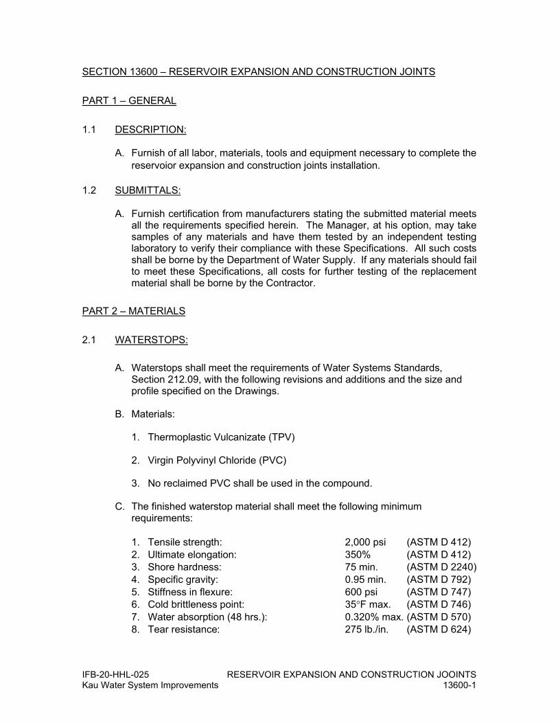
IFB-20-HHL-025 RESERVOIR EXPANSION AND CONSTRUCTION JOOINTS Kau Water System Improvements 13600-1
SECTION 13600 – RESERVOIR EXPANSION AND CONSTRUCTION JOINTS
PART 1 – GENERAL
1.1 DESCRIPTION:
A. Furnish of all labor, materials, tools and equipment necessary to complete the reservoior expansion and construction joints installation.
1.2 SUBMITTALS:
A. Furnish certification from manufacturers stating the submitted material meets all the requirements specified herein. The Manager, at his option, may take samples of any materials and have them tested by an independent testing laboratory to verify their compliance with these Specifications. All such costs shall be borne by the Department of Water Supply. If any materials should fail to meet these Specifications, all costs for further testing of the replacement material shall be borne by the Contractor.
PART 2 – MATERIALS
2.1 WATERSTOPS:
A. Waterstops shall meet the requirements of Water Systems Standards, Section 212.09, with the following revisions and additions and the size and profile specified on the Drawings.
B. Materials:
1. Thermoplastic Vulcanizate (TPV)
2. Virgin Polyvinyl Chloride (PVC)
3. No reclaimed PVC shall be used in the compound.
C. The finished waterstop material shall meet the following minimum requirements: 1. Tensile strength: 2,000 psi (ASTM D 412) 2. Ultimate elongation: 350% (ASTM D 412) 3. Shore hardness: 75 min. (ASTM D 2240) 4. Specific gravity: 0.95 min. (ASTM D 792) 5. Stiffness in flexure: 600 psi (ASTM D 747) 6. Cold brittleness point: 35°F max. (ASTM D 746)
7. Water absorption (48 hrs.): 0.320% max. (ASTM D 570) 8. Tear resistance: 275 lb./in. (ASTM D 624)

IFB-20-HHL-025 RESERVOIR EXPANSION AND CONSTRUCTION JOOINTS Kau Water System Improvements 13600-2
D. VINYLEX, 3400 Tree Court Industrial Blvd., St. Louis, MO 63122 (Phone 800-325-3602) and GREENSTREAK PLASTIC PRODUCTS, Box 7139, St. Louis, MO 63177 (phone 314-225-9400) are two of several suppliers who can furnish waterstops meeting these requirements. Approved equal materials may also be used.
E. Waterstop intersection joints shall be prefabricated with a 12-inch minimum length from the joint.
2.2 JOINT SEALERS:
A. Joints, not requiring waterstops or when so indicated on the Drawings, shall be sealed with a mastic joint sealer material of uniform, stiff consistency that does not contain solvents.
B. The mastic shall tenaciously adhere to primed concrete surfaces, shall remain permanently mastic and shall not contaminate potable water.
C. The material shall be of a type that will effectively and permanently seal joints subject to movements in concrete.
D. The mastic joint sealer shall be an acceptable two part, self-leveling (or gun grade), non-staining, polyurethane elastomeric sealant that cures at ambient temperature. Acceptable sealants shall conform to ASTM C 920 or Federal Specification TT S 00227E.
E. For sloping joints, vertical joints and overhead horizontal joints, only "non-sag" compounds shall be used; all such compounds shall conform to the requirements of ANSI/ASTM C 920 Class 12-1/2, or Federal Specification TT-S-0027 E (3), Type II.
F. For plane horizontal joints, the self-leveling compounds which meet the requirements of ANSI/ASTM C 920 Class 25, or Federal Specification TT-S-0027 E (3), Type I shall be used. For joints subject to either pedestrian or vehicular traffic, a compound providing non-tracking characteristics, and having a Shore "A" hardness range of 25 to 35, shall be used.
G. Primer materials, if recommended by the sealant manufacturer, shall conform to the printed recommendations of the sealant manufacturer.
H. Acceptable polyurethane materials are PSI-270 RESERVOIR SEALANT, as manufactured by POLYMERIC SYSTEMS, INC., Phoenixville, PA (610-935-1170), SIKAFLEX/2C POLYURETHANE ELASTOMERIC SEALANT, as manufactured by SIKA CHEMICAL CORP., Santa Fe Springs, CA (310-941-0231) and SELECT SEAL U-227 RESERVOIR GRADE, as manufactured by SELECT PRODUCTS CORP., Costa Mesa, CA (714-429-0808), or approved equal.

IFB-20-HHL-025 RESERVOIR EXPANSION AND CONSTRUCTION JOOINTS Kau Water System Improvements 13600-3
2.3 PREFORMED JOINT FILLER:
A. Preformed joint filler material shall be of the preformed non-extruding type joint filler constructed of cellular neoprene sponge rubber or polyurethane of firm texture. Bituminous fiber type will not be permitted. All non-extruding and resilient-type preformed expansion joint fillers shall conform to the requirements and tests set forth in ASTM D 1752 for Type I, except as otherwise specified herein.
2.4 BACKING ROD:
A. Backing rod shall be an extruded closed-cell, polyethylene foam rod. The material shall be compatible with the joint sealant material used and shall have a tensile strength of not less than 40 psi and a compression deflection of approximately 25 percent at 8 psi. The rod shall be 1/8-inch larger in diameter than the joint width except that a one-inch diameter rod shall be used for a ¾-inch wide joint.
2.5 BOND BREAKER:
A. Bond breaker shall be SUPER BOND BREAKER WATER BASE as manufactured by Burke Company, San Mateo, California; SELECT EMULSION CURE 309, as distributed by Select Products Co., Costa Mesa, CA (clear or white pigmented) or equivalent. Fugitive dye may be used in bondbreakers if recommended by manufacturer.
PART 3 – EXECUTION
3.1 WATERSTOP INSTALLATION:
A. The waterstop shall be correctly positioned in the forms with the center of the waterstop centered on the joint.
B. In cases where preformed expansion joint material is used in conjunction with the waterstop, allowance shall be made for equal waterstop embedment on each side in the concrete.
C. Waterstop shall be held in place in the forms by use of a split form or other approved method that will positively hold the waterstop in the correct position and to the correct alignment.
D. All waterstop intersection joints shall be welding in the shop and shipped to the project site.
E. Field Joints 1. Field joints shall be restricted to properly aligned, straight butt joints only.
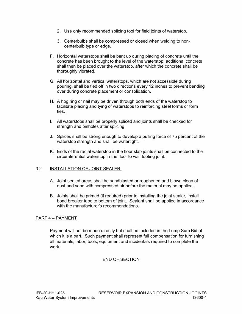
IFB-20-HHL-025 RESERVOIR EXPANSION AND CONSTRUCTION JOOINTS Kau Water System Improvements 13600-4
2. Use only recommended splicing tool for field joints of waterstop.
3. Centerbulbs shall be compressed or closed when welding to non-centerbulb type or edge.
F. Horizontal waterstops shall be bent up during placing of concrete until the
concrete has been brought to the level of the waterstop; additional concrete shall then be placed over the waterstop, after which the concrete shall be thoroughly vibrated.
G. All horizontal and vertical waterstops, which are not accessible during pouring, shall be tied off in two directions every 12 inches to prevent bending over during concrete placement or consolidation.
H. A hog ring or nail may be driven through both ends of the waterstop to facilitate placing and tying of waterstops to reinforcing steel forms or form ties.
I. All waterstops shall be properly spliced and joints shall be checked for strength and pinholes after splicing.
J. Splices shall be strong enough to develop a pulling force of 75 percent of the waterstop strength and shall be watertight.
K. Ends of the radial waterstop in the floor slab joints shall be connected to the circumferential waterstop in the floor to wall footing joint.
3.2 INSTALLATION OF JOINT SEALER:
A. Joint sealed areas shall be sandblasted or roughened and blown clean of dust and sand with compressed air before the material may be applied.
B. Joints shall be primed (if required) prior to installing the joint sealer, install bond breaker tape to bottom of joint. Sealant shall be applied in accordance with the manufacturer's recommendations.
PART 4 – PAYMENT
Payment will not be made directly but shall be included in the Lump Sum Bid of which it is a part. Such payment shall represent full compensation for furnishing all materials, labor, tools, equipment and incidentals required to complete the work.
END OF SECTION

IFB-20-HHL-025 RESERVOIR WALL, BASE, AND TOP JOINTS Kau Water System Improvements 13700-1
SECTION 13700 – RESERVOIR WALL, BASE, AND TOP JOINTS
PART 1 – GENERAL
1.1 DESCRIPTION:
A. Furnish of all labor, materials, tools and equipment necessary to complete the reservoir wall, base, and top joints
1.2 SUBMITTALS:
A. The Contractor shall provide the Manager a 2-foot minimum length of each of the closed cell neoprene pads and the neoprene bearing pads in order to test the pads for compliance with these Specifications.
B. Furnish certified mill certificates showing that the material meets all of the requirements specified here in. The Manager, at DWS option, may take samples of any materials and have them tested by an independent testing laboratory to verify their compliance with these Specifications. All such costs shall be borne by the DWS. If any materials should fail to meet these Specifi-cations, all costs for further testing of the replacement material shall be borne by the Contractor.
C. For manufactured items submit product data sheets indicating the properties of the proposed item meet the requirements of these specifications.
PART 2 - MATERIALS
2.1 WATERSTOPS:
A. Waterstops shall conform to requirements in Section 13600 - RESERVOIR EXPANSION AND CONSTRUCTION JOINTS. The size and location of the waterstop shall be as shown on the Drawings.
2.2 NEOPRENE BEARING PADS:
A. Neoprene pads shall be of dimensions and hardness shown on the Drawings and shall be made by an approved manufacturer.
B. The material for 40 durometer neoprene pads shall conform to ASTM D-2000 M2BC414A14C12F17 and the material for 30 durometer neoprene pads shall conform to ASTM D-2000 M2BC310A14C12F17.
C. Unless otherwise specified on the Drawings, neoprene pads shall be of 40 durometers.
D. DACOM INDUSTRIES CO., 10661 N. Lombard, Portland, OR 97203 (Phone
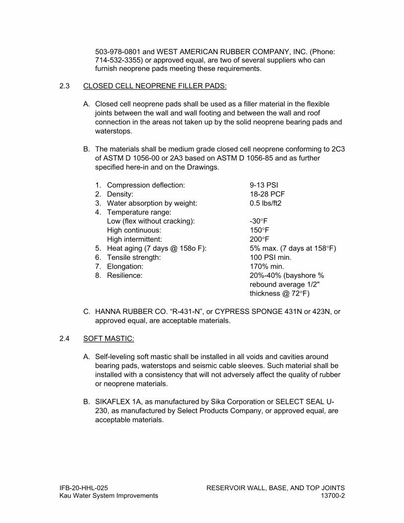
IFB-20-HHL-025 RESERVOIR WALL, BASE, AND TOP JOINTS Kau Water System Improvements 13700-2
503-978-0801 and WEST AMERICAN RUBBER COMPANY, INC. (Phone: 714-532-3355) or approved equal, are two of several suppliers who can furnish neoprene pads meeting these requirements.
2.3 CLOSED CELL NEOPRENE FILLER PADS:
A. Closed cell neoprene pads shall be used as a filler material in the flexible
joints between the wall and wall footing and between the wall and roof connection in the areas not taken up by the solid neoprene bearing pads and waterstops.
B. The materials shall be medium grade closed cell neoprene conforming to 2C3 of ASTM D 1056-00 or 2A3 based on ASTM D 1056-85 and as further specified here-in and on the Drawings. 1. Compression deflection: 9-13 PSI 2. Density: 18-28 PCF 3. Water absorption by weight: 0.5 lbs/ft2 4. Temperature range:
Low (flex without cracking): -30°F High continuous: 150°F
High intermittent: 200°F 5. Heat aging (7 days @ 158o F): 5% max. (7 days at 158°F) 6. Tensile strength: 100 PSI min. 7. Elongation: 170% min. 8. Resilience: 20%-40% (bayshore %
rebound average 1/2" thickness @ 72°F)
C. HANNA RUBBER CO. “R-431-N”, or CYPRESS SPONGE 431N or 423N, or
approved equal, are acceptable materials. 2.4 SOFT MASTIC:
A. Self-leveling soft mastic shall be installed in all voids and cavities around bearing pads, waterstops and seismic cable sleeves. Such material shall be installed with a consistency that will not adversely affect the quality of rubber or neoprene materials.
B. SIKAFLEX 1A, as manufactured by Sika Corporation or SELECT SEAL U-230, as manufactured by Select Products Company, or approved equal, are acceptable materials.

IFB-20-HHL-025 RESERVOIR WALL, BASE, AND TOP JOINTS Kau Water System Improvements 13700-3
PART 3 – EXECUTION
3.1 WATERSTOP INSTALLATION:
A. Waterstops shall be continuous and shall be installed where shown. The method of installation shall be as specified in Section 13600 – RESERVOIR EXPANSION AND CONSTRUCTION JOINTS.
3.2 BEARING AND NEOPRENE FILLER PADS:
A. Bearing and filler pads shall be installed as indicated on the Drawings.
B. Bearing and filler pads shall be glued to the concrete with an approved rubber cement material to prevent uplift of the pads during placement of concrete.
C. In addition, all pads shall be held down with approved plastic shim plates or ‘adobes’ placed under the reinforcing steel as shown.
D. Nailing down pads will not be permitted.
E. All voids and cavities between bearing and filler pads, waterstop and seismic cable sleeves, irrespective of whether these voids are large or small, shall be filled with a soft mastic.
F. Closed cell neoprene shall be ordered at least 1/4 inch wider than theoretically required to facilitate placing and to reduce development of voids between filler pads, bearing pads and waterstops.
G. Contractor's workmanship shall be such that no cement grout or concrete seepage will occur through the bearing and filler pad area resulting in a restraint of radial wall movements.
H. Neoprene bearing pads and one or more closed cell neoprene pads are required between the top of the wall and the underside of the roof. Secure pads as described above in item #2. Trim closed cell neoprene pads as required to fit around seismic tubes at top of wall. Any void areas between such pads shall be filled with soft mastic to prevent any mortar from the roof pour to come into contact with the wall top.
PART 4 – PAYMENT
Payment will not be made directly but shall be included in the Lump Sum Bid of which it is a part. Such payment shall represent full compensation for furnishing all materials, labor, tools, equipment and incidentals required to complete the work.
END OF SECTION

IFB-20-HHL-025 BASIC MATERIALS AND METHODS Kau Water System Improvements – Phase 1 16050-1
DIVISION 16 – ELECTRICAL
SECTION 16050 –BASIC MATERIALS AND METHODS
PART 1 – GENERAL
1.1 GENERAL CONDITIONS
The General Provisions and Special Provisions preceding specification shall
govern this Section.
1.2 SUMMARY
A. This section provides the specifications for general electrical work. See other specification sections for more detailed specifications related to specific
electrical systems.
B. Specification and Drawings complement each other and what is specified, scheduled or mentioned by one shall be binding as if called for by both.
Specification and Drawings are intended to specify nature, quantity and
quality of electrical work.
C. The Contractor shall furnish all labor, materials, tools, equipment, electricity, fuel, shipping and delivery, and appliances required to provide all Electrical
Work, complete, as indicated on the drawings and/or as specified herein.
The drawings note various sizes of equipment as determined for basis of design; the electrical work, however, shall be installed to comply with the
equipment furnished by the successful supplier and shall be based on the
approved shop drawing submittals. The work shall include but not necessarily
be limited to, the following:
1. Complete underground service entrance raceways, including all
handholes and pullboxes required for electric utility services.
2. Complete Hawaii Electric Light Company utility metering system,
including all appurtenances for a complete system.
3. Complete service equipment and grounding system.
4. Complete electrical system for the tank site.
5. Coordination with Hawaii Electric Light Company for power services.
6. Connection and testing of appliances and equipment furnished by others
requiring electrical connections.
7. Final adjustment and testing of the complete electrical installation.
8. The Contractor shall make arrangements with the Hawaii Electric Light
Company for electrical service to the site, as indicated on plans. The
Contractor shall provide service equipment and suitable metering
provisions.
9. The Owner shall pay only non-recurring off-site power service charges
incurred in providing this service but the Contractor shall pay for services

IFB-20-HHL-025 BASIC MATERIALS AND METHODS Kau Water System Improvements – Phase 1 16050-2
and all other work pertaining to this contract and shall coordinate the request and installation so service is available when required for testing
and completion of the contract.
D. During bidding and construction, Contractor shall coordinate his work with
utilities and other trades to avoid omissions and overlapping responsibilities. Electrical Contractor shall notify other trades and suppliers of project voltages
and of existing equipment when new work must be compatible with existing
conditions.
1.3 RELATED WORK SPECIFIED IN OTHER SECTIONS
A. Materials Connected But Furnished & Installed Under Other Sections: This
list is for the convenience of the Contractor, and materials connected are not
necessarily limited by this list.
1. Level transmitters
2. Flow transmitters
3. Pressure transmitters
4. Meters and final connection of service provided by Hawaii Electric Light
Company
5. Equipment utilizing electricity shall be provided by respective sections of this contract. Installation of equipment complete with power wiring and
electric controls and interlock wiring shall be part of Electrical Work.
1.4 SUBMITTALS
A. Submit in accordance with Section 01300 - SUBMITTALS.
B. Shop drawings and catalogue cuts for substitute materials shall clearly
specify compliance with and/or deviation from specified material. Certification
shall not contain statements to imply that the item does not meet requirements specified, such as "as good as"; and "achieve the same end
use and results as materials formulated in accordance with the referenced
publications". Certifications shall simply state that the item conforms to the requirements specified. Certificates shall be printed on the manufacturer's
letterhead and shall be signed by the manufacturer's official authorized to
sign certificates of compliance. Review of shop drawings and catalogue cuts
shall not release Contractor from complying with intent of specification and
drawings. Partial or incomplete submittals will be returned without review.
C. Shop Drawings: Submit complete shop drawings and manufacturer's
literature for the Engineer's review before any work is ordered or fabricated. All submittals shall bare the approval of the general contractor and the
electrical contractor. Partial or incomplete submittals or submittals lacking
the general contractor’s and electrical contractor’s approval will be returned
without review. Submit manufacturer's literature for the following:
1. Panelboards
2. Enclosures and Cabinets
3. Junction Boxes
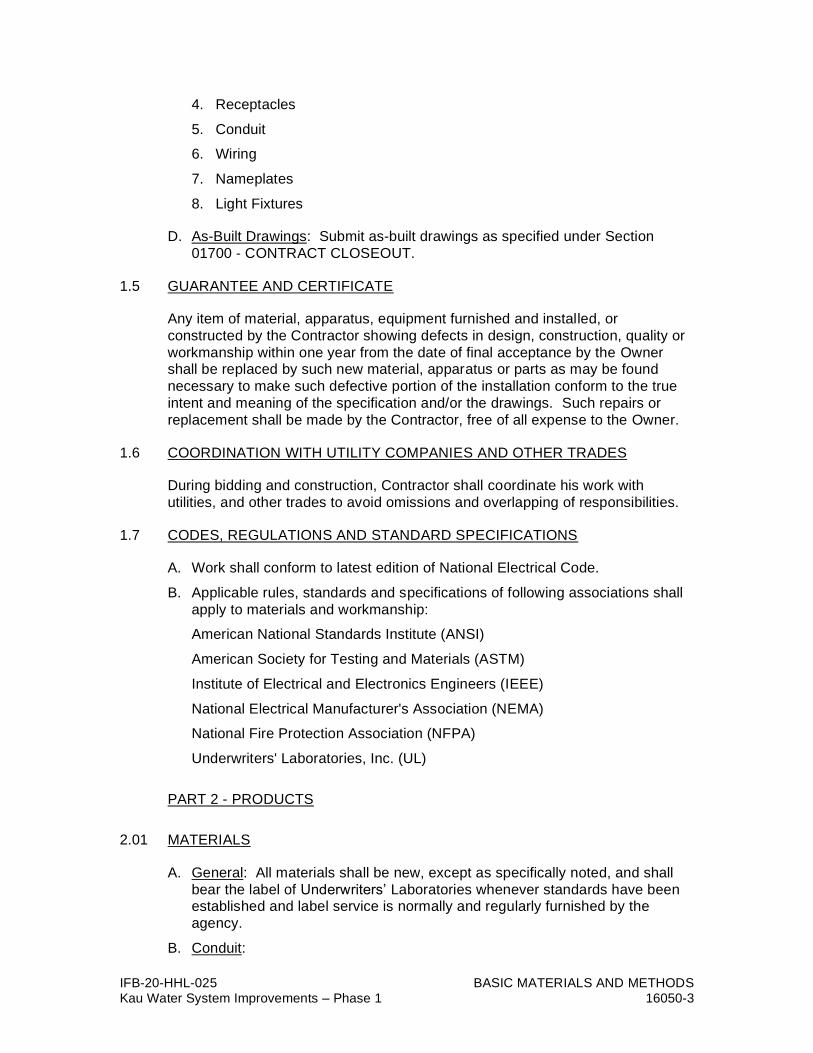
IFB-20-HHL-025 BASIC MATERIALS AND METHODS Kau Water System Improvements – Phase 1 16050-3
4. Receptacles
5. Conduit
6. Wiring
7. Nameplates
8. Light Fixtures
D. As-Built Drawings: Submit as-built drawings as specified under Section
01700 - CONTRACT CLOSEOUT.
1.5 GUARANTEE AND CERTIFICATE
Any item of material, apparatus, equipment furnished and installed, or
constructed by the Contractor showing defects in design, construction, quality or
workmanship within one year from the date of final acceptance by the Owner shall be replaced by such new material, apparatus or parts as may be found
necessary to make such defective portion of the installation conform to the true
intent and meaning of the specification and/or the drawings. Such repairs or
replacement shall be made by the Contractor, free of all expense to the Owner.
1.6 COORDINATION WITH UTILITY COMPANIES AND OTHER TRADES
During bidding and construction, Contractor shall coordinate his work with
utilities, and other trades to avoid omissions and overlapping of responsibilities.
1.7 CODES, REGULATIONS AND STANDARD SPECIFICATIONS
A. Work shall conform to latest edition of National Electrical Code.
B. Applicable rules, standards and specifications of following associations shall
apply to materials and workmanship:
American National Standards Institute (ANSI)
American Society for Testing and Materials (ASTM)
Institute of Electrical and Electronics Engineers (IEEE)
National Electrical Manufacturer's Association (NEMA)
National Fire Protection Association (NFPA)
Underwriters' Laboratories, Inc. (UL)
PART 2 - PRODUCTS
2.01 MATERIALS
A. General: All materials shall be new, except as specifically noted, and shall
bear the label of Underwriters’ Laboratories whenever standards have been established and label service is normally and regularly furnished by the
agency.
B. Conduit:

IFB-20-HHL-025 BASIC MATERIALS AND METHODS Kau Water System Improvements – Phase 1 16050-4
1. Conduits: EMT and galvanized rigid steel, 3/4" minimum diameter with compression or threaded fittings, respectively. Aluminum conduits shall
not be used.
2. Non-Metallic Conduit: PVC Schedule 40, 3/4" minimum diameter.
3. Flexible Conduit: 3/4" minimum, zinc-coated inside and outside; for damp, wet, moist, or corrosive areas -- liquid-tight with factory fittings and
UV stabilized PVC jacket.
C. Conductors: Conductors shall be copper, No. 12 AWG minimum; No. 10 AWG and smaller, solid and round; No. 8 AWG and larger, 7 or 19 strands
concentric. All conductors No. 6 and smaller shall be types THW for interior
use or RHW for exterior use. All conductors No. 4 AWG and larger shall be
type THWN-2 for interior use; or RHW-2 or USE-2 for exterior use.
D. Outlet and Small Junction Boxes: Pressed, zinc-coated steel, minimum
nominal size 4", minimum depth 1-1/2", with raised cover- ring for devices in
concrete masonry units. Exposed boxes and weather exposed boxes shall be ferrous alloy, prime painted and enamel finished, with threaded hubs for
conduit connection. Surface mounted boxes shall be smooth walled with
clean 90 degree corners.
E. Large Junction Boxes: For dry interior locations, the box shall be fabricated
from NEC gauge galvanized steel with matching screw-on type cover, field
punched knockouts. Flush mounted junction boxes shall have flange type covers. For exterior, damp, wet, or corrosive locations, boxes shall be NEMA
4X stainless steel (316), pad lockable. All screws and hardware shall be
stainless steel (316).
F. Enclosures and Cabinets: Enclosures and cabinets for panelboards, enclosed circuit breakers, and safety disconnect switches shall be NEMA
type, fabricated from galvanized steel, or as indicated, prime painted and
enamel finished according to NEMA specifications. For dry interior locations, enclosures shall be NEMA 1. For exterior, damp, wet, or corrosive locations,
enclosures shall be NEMA 4X stainless steel (316) with stainless steel (316)
fasteners and hardware, pad lockable. Provide enclosures made of
continuous welds. Enclosures made of bolted panels/parts will not be
allowed.
G. Device and Cover Plates:
1. Device covers outlets in damp, wet, or corrosive locations shall be weatherproof with lockable stainless steel (316) covers. Covers shall
permit plugs to be connected without compromising the integrity of the
protective nature of the cover while in use.
H. Convenience Single and Duplex Receptacles:
1. Single and Duplex, 20 ampere, 125-volt, back and side wired, 3 wires,
grounding type in ivory plastic body (provide red body for receptacles on
emergency circuits), specification grade, with parallel and ground U-shaped slots. Enclose in outlet box and device plate. Hubbell
SNAP5262, Leviton No. 5362 or pre-approved equal.

IFB-20-HHL-025 BASIC MATERIALS AND METHODS Kau Water System Improvements – Phase 1 16050-5
2. Ground Fault Circuit Interrupting (GFCI) receptacles shall be similar to the above except shall have test and reset switches and maximum allowable
leakage current shall be 5 milli-amperes. Receptacles in damp and wet
locations shall be of the GFCI type.
3. Receptacles installed in exterior, damp, or wet locations shall be UL
Listed weather resistant per NEC 406.9(A).
I. Panelboard: Flush-mounted or surface-mounted as noted, ratings as
indicated, 1-phase, 3WSN, ground bus, copper bussing, circuit breaker complement as shown, complete with lockable door, trim, type written
directory, and 2-ply nameplate. Short circuit amperes interrupting capacity
withstand ratings as indicated. Series rated panelboards not allowed. Full pole circuit breakers (half pole circuit breakers not allowed). Flush mounted
panelboards shall be provided with flange type covers. Lockable with all new
locks keyed alike. Eaton, Square D, General Electric, Siemens or pre-
approved equal.
J. Surge Protective Device (SPD): Provide an SPD in panelboards where
indicated on the drawings. Each SPD shall be bus connected for parallel
operation, rated for 120/240V, 1-phase, 3-wire systems, and have a minimum surge rating of 50kA per phase. The SPD shall be UL 1449 and UL 1283
Listed (latest editions). Each SPD shall have LED status indicator lights.
K. Nameplates: Laminated nameplates shall be provided for each panelboard, junction box, and cabinet for identification purposes. Nameplates shall be
laminated plastic shall be 1/8-inch thick Melamine plastic, black with white
center core. Letters, numbers, symbols, or pictographs shall be incised a
minimum of 1/32-inch into the plastic to expose the white core. Size of nameplate shall be 1-inch by 2-1/2 inches minimum. Lettering shall be
minimum 1/4-inch high normal block lettering. Equipment designations shall
be as indicated on the Drawings.
L. Light Switches: Single or double pole, 3 or 4 way, as required, non-mercury,
quiet, 20 amperes, 120-277 volt, UL labeled AC type, silvered contacts, ivory,
tumbler switch with endurance of 10,000 make-breaks. Enclose in outlet box
and device plate.
M. Light Fixtures: Provide light fixtures complete with necessary lamps, ballasts,
starters, and accessories, according to the "Light Fixture Schedule".
1. LED Drivers shall consist of a high frequency inverter, and power control and regulation circuitry. Drivers shall be Class 2 certified and
meet safety standard UL 1310.
N. Hardware, Supports, Backing, Etc.: All hardware, fasteners, supports, backing and other accessories necessary to install electrical equipment shall
be provided. Wood materials shall be "wolmanized" treated against termites,
iron or steel materials shall be galvanized for corrosion protection, and
non-ferrous materials shall be brass or bronze. Installations in damp, wet, or
corrosive locations shall be of stainless steel, 316.

IFB-20-HHL-025 BASIC MATERIALS AND METHODS Kau Water System Improvements – Phase 1 16050-6
PART 3 - EXECUTION
3.01 GENERAL
A. Rules and Permit: The entire installation shall be made in strict accordance
with the latest rules and regulations of the National Board of Fire Underwriters, the currently adopted edition of the National Electrical Code
and the Electrical Branch of the local Building Department. The Contractor
shall obtain and pay for the electrical permit as required by local laws and rules. All work shall be inspected by the proper local authorities as it
progresses. The Contractor shall pay all inspection fees and shall deliver
certificates of completion and inspection to the Engineer before final payment will be made. Costs of permits and inspection fees shall be included in the
Contractor's bid price.
B. Construction Methods: Construction shall conform to construction practices
as recommended by the American Electricians Handbook by Croft (latest edition), Edison Electric Institute, National Electrical Code, National fire
Protection Association, National Electrical Safety Code and applicable
instructions of manufacturers of equipment and material supplied for this
project.
C. Materials and Workmanship: All labor and materials of every kind shall be
subject to the approval of the Engineer, who shall be afforded every facility
for ascertaining the competence of such labor and examining such materials as they may deem necessary. Concealed work, handholes, and enclosures
shall be reopened / opened at random as directed during inspections by the
Engineer. Materials shall be new and shall bear the listed label of the Underwriters' Laboratories, Inc. Brand names and catalog numbers used in
this specification indicate the standards of design and quality required.
Substitution of other brands or catalog numbers shall conform to the requirements in the Bidding Documents. All high voltage work shall be
performed by qualified electricians certified to work on high voltage systems.
D. Record Drawings: The Contractor shall maintain an accurate and adequate
record of each change as it occurs, regardless of how ordered.
E. Drawings and Specification: This specification is intended to cover all labor,
materials and standards of workmanship to be employed in the work
indicated on the Drawings and called for in the specification or reasonably implied therein. The Drawings and specification supplement one another.
Any part of the work mentioned in one and not represented in the other, shall
be done the same as if it has been mentioned in both. The Contractor shall
not make alterations in the Drawings and specification.
F. Discrepancies and Interpretations:
1. Should the Contractor find any discrepancies in or omissions from any of
the documents or be in doubt as to their meaning, he shall advise the Engineer who will issue any necessary clarification within a time period
which does not disrupt the progress of the work.
2. All interpretation and supplemental instructions will be in the form of a
written addenda to the Contract Documents.
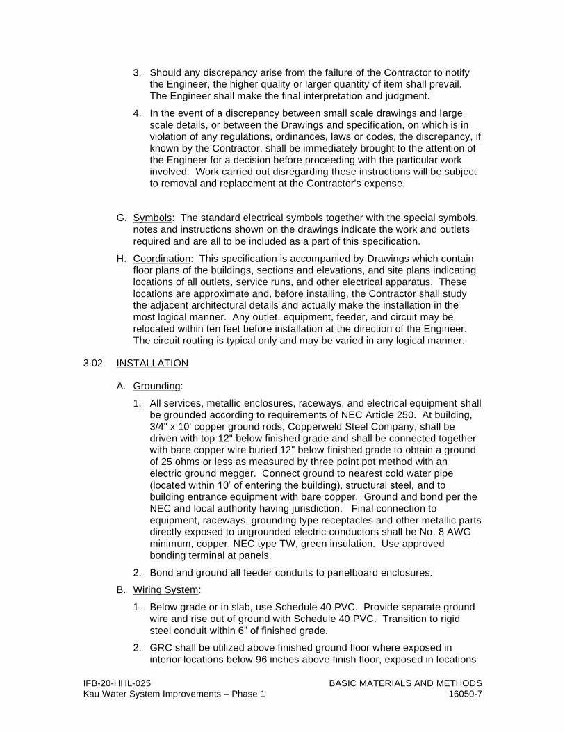
IFB-20-HHL-025 BASIC MATERIALS AND METHODS Kau Water System Improvements – Phase 1 16050-7
3. Should any discrepancy arise from the failure of the Contractor to notify the Engineer, the higher quality or larger quantity of item shall prevail.
The Engineer shall make the final interpretation and judgment.
4. In the event of a discrepancy between small scale drawings and large
scale details, or between the Drawings and specification, on which is in violation of any regulations, ordinances, laws or codes, the discrepancy, if
known by the Contractor, shall be immediately brought to the attention of
the Engineer for a decision before proceeding with the particular work involved. Work carried out disregarding these instructions will be subject
to removal and replacement at the Contractor's expense.
G. Symbols: The standard electrical symbols together with the special symbols,
notes and instructions shown on the drawings indicate the work and outlets
required and are all to be included as a part of this specification.
H. Coordination: This specification is accompanied by Drawings which contain floor plans of the buildings, sections and elevations, and site plans indicating
locations of all outlets, service runs, and other electrical apparatus. These
locations are approximate and, before installing, the Contractor shall study the adjacent architectural details and actually make the installation in the
most logical manner. Any outlet, equipment, feeder, and circuit may be
relocated within ten feet before installation at the direction of the Engineer.
The circuit routing is typical only and may be varied in any logical manner.
3.02 INSTALLATION
A. Grounding:
1. All services, metallic enclosures, raceways, and electrical equipment shall be grounded according to requirements of NEC Article 250. At building,
3/4" x 10' copper ground rods, Copperweld Steel Company, shall be
driven with top 12" below finished grade and shall be connected together with bare copper wire buried 12" below finished grade to obtain a ground
of 25 ohms or less as measured by three point pot method with an
electric ground megger. Connect ground to nearest cold water pipe
(located within 10’ of entering the building), structural steel, and to building entrance equipment with bare copper. Ground and bond per the
NEC and local authority having jurisdiction. Final connection to
equipment, raceways, grounding type receptacles and other metallic parts directly exposed to ungrounded electric conductors shall be No. 8 AWG
minimum, copper, NEC type TW, green insulation. Use approved
bonding terminal at panels.
2. Bond and ground all feeder conduits to panelboard enclosures.
B. Wiring System:
1. Below grade or in slab, use Schedule 40 PVC. Provide separate ground
wire and rise out of ground with Schedule 40 PVC. Transition to rigid
steel conduit within 6” of finished grade.
2. GRC shall be utilized above finished ground floor where exposed in
interior locations below 96 inches above finish floor, exposed in locations

IFB-20-HHL-025 BASIC MATERIALS AND METHODS Kau Water System Improvements – Phase 1 16050-8
under cover but not totally enclosed with walls, and exposed on the exterior of the building. GRC shall be supported off the finish floor with
conduit support block.
3. All wiring shall be installed in conduits except as noted.
4. Conduit system shall be continuous from outlet to outlet and fitting to fitting so that electrical continuity is obtained between all conduits of the
system.
5. Conduits cut square and inner edges reamed. Butt together evenly within
couplings.
6. Make bends and offsets with hickey or conduit-bending machine. Do not
use vise or pipe tee. Flattened or crushed conduit not acceptable.
7. Use of running threads not permitted. Where conduits cannot be joined
by standard threaded couplings, approved water-tight conduit unions shall
be used.
8. Cap conduits during construction with plastic or metal-capped bushings to
prevent entrance of dirt and moisture. Swab all conduits and dry before
installing wires. Provide removable watertight conduit seals on all conduits entering the building, or pad mounted equipment, where the
conduit is connected to manholes, handholes, or other pad mounted
equipment.
9. Pullstrings shall be placed in all empty / spare conduits ten feet in length
or longer.
10. Install insulating bushings and two locknuts on each end of every conduit
run at enclosures and boxes. Provide grounding bushings as required.
C. Conductors:
1. Mechanical means for pulling shall be torque-limiting type and not used
for #2 AWG and smaller wires.
2. Pulling tension shall not exceed wire manufacturer's recommendations.
3. Where necessary, powdered soapstone may be used as a lubricant for
drawing wires through conduit. No other means of lubricating will be
allowed.
4. Form neatly in enclosures for minimum of crossovers. Tag all feeders
and label all branch circuits in all enclosures and devices. Identify panel
name and branch circuit number.
5. Color code feeder, branch circuit, and grounding conductors. Color for
grounding conductors shall be green. Color for neutral conductors shall
be white except for where neutrals of more than one branch circuit grouping are installed in the same raceway or enclosure, the other neutral
shall be white with a colored stripe (other than green). The color coding
for three-phase and single-phase circuits shall be as follows:
208Y/120V, 3-phase, 4-wire:
Black (Phase-A)

IFB-20-HHL-025 BASIC MATERIALS AND METHODS Kau Water System Improvements – Phase 1 16050-9
Red (Phase-B)
Blue (Phase-C)
480Y/277V, 3-phase, 4-wire:
Brown (Phase-A)
Orange (Phase-B)
Yellow (Phase-C)
120/240V, 1-phase, 3-wire:
Red and Black
D. Splicing of Wire and Cable:
1. Wires shall be formed neatly in enclosures and boxes.
2. Splices made according to NEC Article 110.
3. Splices shall be reinsulated. Remove all sharp points that can pierce
tape. Use Minnesota Mining and Manufacturing Co. "Scotch" #33 tape,
or pre-approved equal. Splices in pull boxes shall be water-tight.
E. Trench Excavation:
1. Dimensions and locations of trenches for pullboxes and ductlines shall be
as indicated on drawings. Trench width and depths shall be sufficient to
accommodate proper installation of conduit banks and cables.
2. Where a trench is excavated on slope, sides are to be vertical, and depth
measured at lowest side. All measurements are to be based on final
grades.
3. Bottom of trenches to be flat and smooth.
4. Trenches shall be widened at pullbox sites to permit proper entry of ducts.
5. All excavations for pullboxes in excess of the required depths shall be
filled with concrete.
6. Sheathing and bracing as required shall be provided to support sides of
excavations from cave-ins.
7. Excavated material may be placed alongside trench.
F. Backfill:
1. Backfilling shall be to finished grades indicated on accompanying
drawings, and matching existing conditions.
2. Backfill material shall be completely free of wood or other debris.
3. Backfill material shall be placed in maximum of 12" layers in loose
thickness before compacting. Backfill shall be thoroughly compacted with
hand or mechanical tampers, and in no case shall tamping be
accomplished by using the wheels or tracks of a vehicle.
G. Conduit and Duct Bank:
1. Bottom of trenches for all systems shall be clean, smooth and well graded
prior to installation of conduits.

IFB-20-HHL-025 BASIC MATERIALS AND METHODS Kau Water System Improvements – Phase 1 16050-10
2. Saw cut, ream and taper ducts and conduits with manufacturers'
approved tool.
3. Couplings and bells shall be tight to prevent entry of dirt into ducts and
conduits.
4. Provide spacers to maintain proper separation between ducts.
5. Changes in direction of greater than 5 shall be accomplished by using special couplings or bends manufactured for this purpose. Where ducts
enter pullboxes, they shall be terminated in end bells. Ducts shall be
thoroughly cleaned before laying. When it is necessary to cut tapered end of duct at site, cut shall be made with saw and tapered with lathe
designed to match original taper. Coordinate placement of duct runs with
other utilities, structures, existing facilities and landscaping elements to
avoid conflicts. When necessary, obtain acceptance from the Engineer
for relocation and adjustments at no additional cost to the Owner.
6. Ducts shall be clean and free from debris and rubbish.
7. After each day's work, provide temporary conduit plugs at the end of
conduit banks to prevent entry of dirt, rubbish, or debris.
8. Pass smooth bullet-shaped, blunt tip wooden test mandrel through the
entire length of each duct or conduit to test for burrs and obstructions.
Unless indicated otherwise, mandrel shall be 14" long and shall have diameter of 2" less than inside diameter of duct or conduit. If burrs or
obstructions are encountered, that section shall be replaced at no
additional cost to the Owner.
9. Unless indicated otherwise, install #12 AWG galvanized iron pulling wire
or polypropylene cord in each conduit after testing.
10. Apply thin coat of sealing compound on ducts and conduits at couplings
and bells.
11. Provide duct seals at each entry point into pullboxes to prevent water
from flowing between pullboxes.
H. Finishing:
1. All cutting that may be required for complete installation of the electrical
work shall be carefully performed, and all patching shall be finished in
first-class condition by the Contractor.
2. Close unused knockouts in boxes or enclosures with metal cap that will
maintain the rating of the box or enclosure.
3. Wipe clean all exposed raceways and enclosures with rag and solvent. Unfinished raceways and enclosures shall be primed and painted and
finished to blend in with the surface it is mounted on. (Do not cover
nameplates.) Factory finished enclosures shall not be painted, touch up
where required.
I. Miscellaneous Details:
1. Complete all panel circuit directories, using typewriter. Verify "room" and
"use" designations before typing.

IFB-20-HHL-025 BASIC MATERIALS AND METHODS Kau Water System Improvements – Phase 1 16050-11
2. Prime and paint all exposed conduits, hangers, and fasteners.
3. Furnish necessary test equipment and make all tests necessary to check
for unspecified grounding, shorts and wrong connections. Correct faulty
conditions, if any.
4. Tag all empty conduits in switchboard, panelboards, cabinets, at
backboards, etc. and identify destination.
5. Provide arc flash warning labels on all electrical equipment as required by
2014 NEC Article 110.16 and 2015 NFPA-70E 130.5. The contractor shall attain all information required for the calculations, perform the
calculations, and provide the labels at no additional cost.
6. Anchor all free-standing floor mounted electrical equipment, apparatus, and transformers. Provide additional bracing per the seismic conditions
at the site.
3.03 TESTING AND INSPECTION
A. If the Engineer discovers any errors, the Contractor, at his own expense, shall go over all similar portions of the entire job, taking the necessary or
directed remedial action.
B. After completion of all wiring, insulating resistance testing of all power and control circuits shall be performed with a 500-volt megger. The test on each
circuit shall be performed for one minute in the presence of the Engineer or
his representative, and a written test report of the results shall be submitted to the Engineer before acceptance can be obtained. Equipment which may
be damaged during this test should be disconnected. The tests shall be
performed with all other equipment connected to the circuit.
C. After the electrical system installation is completed, and at such time as the Engineer may direct, the Contractor shall conduct an operating test for
approval. The equipment shall be demonstrated to operate in accordance
with the requirements of these specifications. The test shall be performed in the presence of the Engineer or his authorized representative. The
Contractor shall furnish all instruments, electric power and personnel required
for the tests.
D. Wherever test or inspection reveals faulty equipment or installation, the Contractor shall take corrective action, at his own expense, repairing or
replacing equipment or installation as directed.
3.04 MEASUREMENT AND PAYMENT
A. General: No separate payments will be made for the work covered by the
separate section of the 16000 series of these specifications. All costs in
connection with furnishing and installing of the various items in accordance with standard practice, the details shown on the drawings and in accordance
with these specifications, shall be included in the lump sum price of which the
item is a part.
B. Compensation: Payment of the furnishing and installing of equipment will be made at the lump sum price bid of which the item is a part and shall be full

IFB-20-HHL-025 BASIC MATERIALS AND METHODS Kau Water System Improvements – Phase 1 16050-12
compensation for all work in accordance therewith, complete and finished in
accordance with the drawings and specifications.
END OF SECTION

IFB-20-HHL-025 SCADA SYSTEM Kau Water System Improvements – Phase 1 16100-1
DIVISION 16 – ELECTRICAL
SECTION 16100 – SUPERVISORY CONTROL AND DATA ACQUISITION
(SCADA) SYSTEM
PART 1 – GENERAL
1.1 GENERAL CONDITIONS
This section covers the Supervisory Control and Data Acquisition (SCADA)
system including equipment, wiring, adjustment and testing as indicated on the
plans and specified herein.
As specified in Section 16000, Electrical. The provisions of these related
sections apply to this section and work described in this section shall comply with
them.
1.2 SUMMARY
A. Provide all articles, materials, equipment, operations, and services herein or
on Drawings, including all labor, materials, taxes, fees, insurance, and
incidentals required to insure completion.
B. Test Complete Installation: Installation shall be complete in every detail as
specified and ready for use. Any item supplied by Contractor developing
defects within one year of final acceptance by Owner shall be replaced by such materials, apparatus, or parts to make such defective portion of
complete system conform to true intent and meaning of these Drawings and
Specifications, at no cost to Owner.
C. System shall be comprised of one (1) new RTU panel at the new Kau Water
System site. The new RTU system at the site shall be mounted within an
enclosure and shall be compatible to communicate, via radio link to the
existing Master SCADA system at the existing DWS Baseyard. Basic function of the Kau Water System shall be to monitor on site conditions at the
side and receive supervisory signals from the existing Master SCADA
Station, and to telemeter the data back, via radio telemetry. This system shall
require but not limited to the following work:
1. Providing one (1) RTU at the new Kau Water System site, including but not limited to the following major equipment:
a. Siemens Simatic S7-1200 PLC 1214C DC/DC/DC with most current firmware version or approved equal
b. APC Smart-UPS RT 1500VA with Smart-UPS (spare) Battery Pack uninterruptible power supply unit or approved equal
c. 8-Port Unmanaged Ethernet switch
d. Siemens 10” HMI Operator Panel or approved equal
e. 4RF Aprisa SR+ Remote Station radio or approved equal
f. Two (2) Power Supplies

IFB-20-HHL-025 SCADA SYSTEM Kau Water System Improvements – Phase 1 16100-2
g. One (1) Siemens TIA Portal V15 Professional Floating License
2. Providing required modifications and additions to the existing Master SCADA
Station system at the existing DWS Baseyard for adding the new SCADA system at the Kau Water System site.
3. The SCADA communications systems shall be as indicated on the drawings and as follows:
a. Between the new Kau Water System site and the existing DWS Baseyard.
b. The system shall be used for transmitting alarms, status and telemetry,
calculated data, diagnostic and error logging information from the remote RTU to the Master SCADA Station. Remote RTU shall also be able to upload any portion of their database to the Master SCADA Station upon request or event.
c. The Master SCADA System Computer shall be able to send to each remote RTU, commands and interrogation requests, and to download to the RTU the full Database, Application, Software and Parameters, via the
communications channel.
d. The Master SCADA System Computer shall give the operators full visibility and control of the remote RTU operation including database
changes, parameter changes, and full remote diagnostics, as well as source-level application monitoring for the system engineer.
e. The RTU shall be able to communicate and exchange data with each other and/or with hierarchies in the system and to inform the Master
SCADA System about their activity.
f. Contractor shall verify conditions of existing SCADA equipment prior to bidding.
g. Contractor shall coordinate the planning and construction of the SCADA system (programming, I/O list, etc.) with the Owner.
h. The Contractor shall furnish and install a SCADA ready enclosure as indicated on the plans and specified herein.
i. Contractor shall furnish a list of SCADA points for approval prior to fabrication of the SCADA RTU panel.
D. This system shall be an integrated system of hardware and firmware totally
engineered, programmed, assembled and tested. System shall be complete with all appurtenances, whether specifically referenced herein or not, but
which may be required for operation.
E. During bidding and construction, Contractor shall coordinate his work with
other trades to avoid omissions and overlapping responsibilities. Electrical contractor shall notify other trades and suppliers of project voltages, including
control voltages.
F. Work by Others: Instrument transmitters shall be provided by respective sections of this contract. Installation of equipment complete with power
wiring and electric controls and interlock wiring shall be part of Electrical
Work.
1.3 SUBMITTALS

IFB-20-HHL-025 SCADA SYSTEM Kau Water System Improvements – Phase 1 16100-3
A. Submit in accordance with Section 01300 - SUBMITTALS.
B. Shop drawings and catalogue cuts for substitute materials shall clearly
specify compliance with and/or deviation from specified material. Certification
shall not contain statements to imply that the item does not meet
requirements specified, such as "as good as"; and "achieve the same end use and results as materials formulated in accordance with the referenced
publications". Certifications shall simply state that the item conforms to the
requirements specified. Certificates shall be printed on the manufacturer's letterhead and shall be signed by the manufacturer's official authorized to
sign certificates of compliance. Review of shop drawings and catalogue cuts
shall not release Contractor from complying with intent of specification and
drawings. Partial or incomplete submittals will be returned without review.
C. Shop Drawings: Submit complete shop drawings and manufacturer's
literature for the Engineer's review before any work is ordered or fabricated.
All submittals shall bare the approval of the general contractor and the electrical contractor. Partial or incomplete submittals or submittals lacking
the general contractor’s and electrical contractor’s approval will be returned
without review. Submit manufacturer's literature for the following:
1. SCADA system components and equipment
2. Conductors and wiring
3. Wiring and functional or block diagrams
4. Radio equipment including transmitters, receivers, antennas, antenna cables, etc.
5. Manufacturer’s recommendations for installation
6. Logic diagrams and ladder diagrams
7. Manufacturer's recommended list of spare parts for a one-year period of
operation
D. As-Built Drawings: Submit as-built drawings as specified under Section
01700 - CONTRACT CLOSEOUT.
1.4 LOCAL SUPPORT
The manufacturer of the SCADA system supplied shall be represented by a
company with offices in the State of Hawaii. This local office shall be capable of responding to requests for maintenance and repair to the system by having a
technician skilled in the repair, maintenance and operation of the system at the
job site within 24 hours of being notified. This local representative shall carry all
spare parts which are recommended by the manufacturer.
PART 2 - PRODUCTS
2.01 GENERAL
Unless otherwise indicated, provide all first quality, new materials, free from any defects, in first class condition, and suitable for the space provided. New old stock
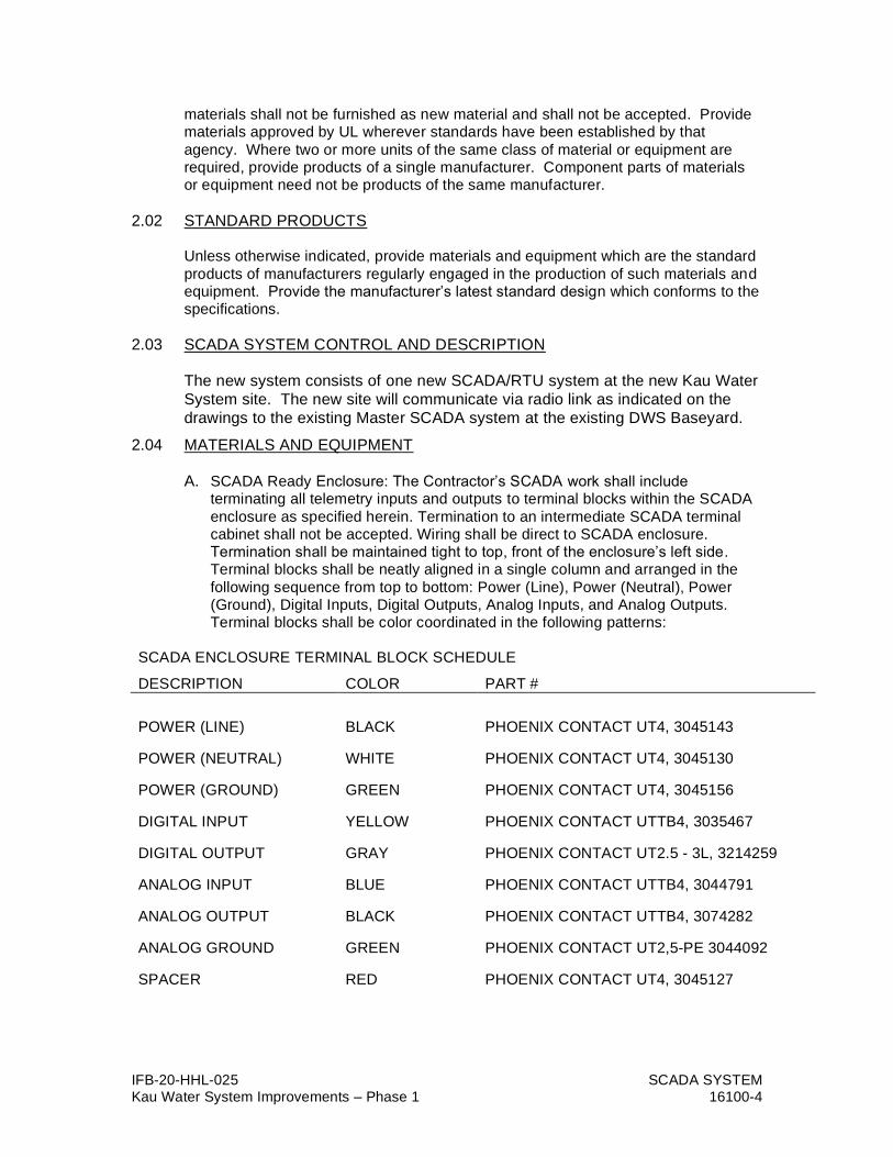
IFB-20-HHL-025 SCADA SYSTEM Kau Water System Improvements – Phase 1 16100-4
materials shall not be furnished as new material and shall not be accepted. Provide materials approved by UL wherever standards have been established by that
agency. Where two or more units of the same class of material or equipment are required, provide products of a single manufacturer. Component parts of materials or equipment need not be products of the same manufacturer.
2.02 STANDARD PRODUCTS
Unless otherwise indicated, provide materials and equipment which are the standard
products of manufacturers regularly engaged in the production of such materials and equipment. Provide the manufacturer’s latest standard design which conforms to the specifications.
2.03 SCADA SYSTEM CONTROL AND DESCRIPTION
The new system consists of one new SCADA/RTU system at the new Kau Water
System site. The new site will communicate via radio link as indicated on the
drawings to the existing Master SCADA system at the existing DWS Baseyard.
2.04 MATERIALS AND EQUIPMENT
A. SCADA Ready Enclosure: The Contractor’s SCADA work shall include terminating all telemetry inputs and outputs to terminal blocks within the SCADA
enclosure as specified herein. Termination to an intermediate SCADA terminal cabinet shall not be accepted. Wiring shall be direct to SCADA enclosure. Termination shall be maintained tight to top, front of the enclosure’s left side. Terminal blocks shall be neatly aligned in a single column and arranged in the
following sequence from top to bottom: Power (Line), Power (Neutral), Power (Ground), Digital Inputs, Digital Outputs, Analog Inputs, and Analog Outputs. Terminal blocks shall be color coordinated in the following patterns:
SCADA ENCLOSURE TERMINAL BLOCK SCHEDULE
DESCRIPTION COLOR PART #
POWER (LINE) BLACK PHOENIX CONTACT UT4, 3045143
POWER (NEUTRAL) WHITE PHOENIX CONTACT UT4, 3045130
POWER (GROUND) GREEN PHOENIX CONTACT UT4, 3045156
DIGITAL INPUT YELLOW PHOENIX CONTACT UTTB4, 3035467
DIGITAL OUTPUT GRAY PHOENIX CONTACT UT2.5 - 3L, 3214259
ANALOG INPUT BLUE PHOENIX CONTACT UTTB4, 3044791
ANALOG OUTPUT BLACK PHOENIX CONTACT UTTB4, 3074282
ANALOG GROUND GREEN PHOENIX CONTACT UT2,5-PE 3044092
SPACER RED PHOENIX CONTACT UT4, 3045127

IFB-20-HHL-025 SCADA SYSTEM Kau Water System Improvements – Phase 1 16100-5
Terminal blocks shall maintain one block spacing between groups, with exception for Power (Line), Power (Neutral) and Power (Ground) which shall be grouped
together. Further, Digital Input, Digital Output, Analog Input and Analog Output shall be segmented into groupings of eight (8) blocks with one block spacing between groupings. Provide ground terminal blocks for each Analog Input and
Analog Output for landing the shield wire.
Contractor’s wiring shall be terminated to left side of terminal blocks, with negative on the base tier and positive on the top tier for double-level terminal blocks; with normally open (N.O.) on the base tier, common on the 2nd tier, and
normally closed (N.C.) on the top tier for multi-level terminal blocks. Wiring shall be marked at both ends with printed wire labels or printed heat shrink tags. Wiring shall be color coordinated as follow:
SCADA ENCLOSURE WIRING SCHEDULE
DESCRIPTION COLOR
POWER (LINE) BROWN
POWER (NEUTRAL) WHITE
POWER (GROUND) GREEN
D.C. (+) RED
D.C. (-) BLACK
DIGITAL OUTPUT (N.O.) PURPLE
DIGITAL OUTPUT (COMMON) YELLOW
DIGITAL OUTPUT (N.C.) ORANGE
ANALOG INPUT (+) BLUE
ANALOG INPUT (-) GRAY
ANALOG GROUND GREEN
ANALOG OUTPUT (+) BLUE
ANALOG OUTPUT (-) GRAY
ANALOG GROUND GREEN
B. The RTU equipment shall be microprocessor based, solid-state construction
utilizing second source semiconductors, unless otherwise specified. Derate
components to assure dependability and long-term stability. Provide printed
or etched circuit boards of glass epoxy, hand or wave soldered, of sufficient thickness to prevent warping. Coat printed circuit boards in field-mounted
equipment with 2 mils of solderable conformal coating complying with MIL-I-
460-58B. Alignment and adjustments shall be noncritical, stable with temperature changes or aging and accomplished with premium grade
potentiometers. Do not insert components of specially selected values into
standard electronic assemblies to meet performance requirement. Use parts

IFB-20-HHL-025 SCADA SYSTEM Kau Water System Improvements – Phase 1 16100-6
indicated in instruction manuals, replaceable with standard commercial components of the same description without degrading performance of
completed assembly. The RTU equipment shall be capable of
communicating with the existing Master Station site PLC equipment. The
RTU equipment shall be provided with a UPS system. The RTU shall have the capability to be expandable. RTU panel shall be fabricated by Dynatek,
Inc.
C. Operator Interface Touchscreen shall be installed within the SCADA Enclosure door, such that it may be operated without opening the cabinet door. Contractor shall confirm mounting location height with Owner prior to installation.
Touchscreen shall a have basic color screen.
Touchscreens shall monitor and control local functions of the RTU and communicate to the RTU using Ethernet communication, through a DIN rail
mounted switch in the RTU panel.
The Touchscreen assembly shall be manufactured by Siemens and rated NEMA 4X. For facilities which only include a reservoir, a 10” Siemens KTP HMI panel
with 640x480 resolution shall be specified.
D. SCADA Hardware: The Contractor shall utilize as required the following list of approved RTU hardware. Hardware shall be the latest version at the time of
construction, during the commencement of electrical portion of work.
1. Siemens S7-1200 1214C DC/DC/DC Firmware ≥ 4.1, CPU
2. Siemens SM1221, Digital Input
3. Siemens SM1222, Digital Output
4. Siemens SM1231, Analog Input 8AI
5. Siemens SM1232, Analog Output
6. Siemens PM1207, Power Switch
7. Siemens XB008, 8-Port Unmanaged Industrial Ethernet Switch
8. Siemens KTP1000, 10” Panel
9. 24VDC, 3.5A Power Supply, Phoenix Contact QUINT-PS/1AC/24DC/3.5, PN# 2866747 (for radio and level transmitter only)
10. 24VDC, 5A Power Supply, Phoenix Contact QUINT-PS/1AC/24DC/5, PN# 2866750 (for radio and level transmitter only)
11. DIN Rails, 35mm x 7.5mm x 2000mm, Aluminum, Phoenix Contact PN# 0804681
12. Terminal Block, Black, Phoenix Contact UT4, PN# 3045143
13. Terminal Block, White, Phoenix Contact UT4, PN# 3045130
14. Terminal Block, Green, Phoenix Contact UT4, PN# 3045156
15. Terminal Block, Red, Phoenix Contact UT4, PN# 3045127
16. Terminal Block, Blue, Phoenix Contact UT4, PN# 3044791
17. Terminal Block, Yellow, Phoenix Contact UT4, PN# 3045114
18. Terminal Block, Gray, Phoenix Contact U2.5-3L, PN# 3214259

IFB-20-HHL-025 SCADA SYSTEM Kau Water System Improvements – Phase 1 16100-7
19. Terminal Block, Gray w/Black, Phoenix Contact UT2.5-3L, PN# 3214262
20. Fuse Terminal Block, Phoenix Contact, UK63-HESI, PN# 3004171
21. 1 Pole, 120/240VAC, 10A, Circuit Breaker, Rockwell 1489-A1C100
22. 2PDT, 24VDC Coil, 10A, Rockwell PN# 700-HC22Z24-3-4
23. Screw Terminal Base Socket, Black, Rockwell PN# 700-HN128
24. Relay Retainer Clips, Rockwell PN# 700-HN114
25. Diode, Motorola 1N4005
26. Terminal Block – Grounding Green/Yellow Phoenix Contact UT2,5-PE
27. Siemens 1241 Communications Module RS485/422 Modbus
E. Radio Equipment and Communications:
1. Communications Path Survey: The Contractor shall perform and furnish a communication path survey to determine the best system to communicate properly between the existing and new SCADA systems. The survey should
simulate use of actual frequency and proposed equipment, and shall determine the gain margin for the proposed transmission path.
a. The survey shall include but not be limited to: a printout graph for each communication path which shall show the path profile, site elevations,
site name, frequency, ERP, antenna type, distance between sites and predicted losses versus desired losses. The Contractor shall design the radio and communication system for at least 99.9% reliability.
b. Radio Path Study: A real world field study shall be performed by the Contractor to confirm the simulated computer path analysis.
2. Licensing: The Contractor shall be responsible for consulting with DWS for instruction on which existing FCC license and frequency to use. The
Contractor shall prepare all paperwork required for FCC coordination and FCC licensing in accordance with the FCC Rules and Regulations governing the licensing of the proposed channels. One VHF frequency shall be
required to accommodate the RTU reception and transmission to the central computer. The Contractor shall submit all FCC coordination requirements to the FCC for frequency approval. The Contractor shall be responsible for the
payment of FCC license fee.
3. FCC Type Acceptance: All equipment related to the radio communication shall be FCC type accepted, indication authorization by the FCC to allow the equipment to be used by the licensee.
F. Radio Equipment: The Contractor shall furnish and install latest edition 4RF Aprisa SR+ Remote Station radios as required by the Kau Water System project. As a minimum, communication equipment and grounding shall be per Motorola
R56 – Standards and Guidelines for Communication Sites. All existing communication equipment, materials and appurtenances shall be replaced. The reuse of existing materials shall be strictly prohibited.
G. Antenna and Accessories: All antenna hardware shall comply with FCC rules and governing the design characteristics and mounting requirements for licensed frequencies used in the SCADA system. In general, the remote station shall employ directional gain antennas. The central computer site will use an omni-
directional gain antenna. Feedlines between antenna and SCADA ready
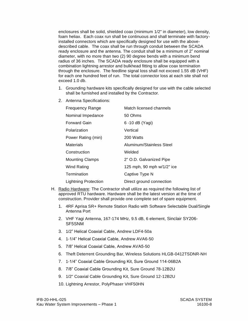
IFB-20-HHL-025 SCADA SYSTEM Kau Water System Improvements – Phase 1 16100-8
enclosures shall be solid, shielded coax (minimum 1/2" in diameter), low density, foam heliax. Each coax run shall be continuous and shall terminate with factory-
installed connectors which are specifically designed for use with the above-described cable. The coax shall be run through conduit between the SCADA ready enclosure and the antenna. The conduit shall be a minimum of 2” nominal
diameter, with no more than two (2) 90 degree bends with a minimum bend radius of 36 inches. The SCADA ready enclosure shall be equipped with a combination lightning arrestor and bulkhead fitting to allow coax termination through the enclosure. The feedline signal loss shall not exceed 1.55 dB (VHF)
for each one hundred feet of run. The total connector loss at each site shall not exceed 1.0 db.
1. Grounding hardware kits specifically designed for use with the cable selected
shall be furnished and installed by the Contractor.
2. Antenna Specifications:
Frequency Range Match licensed channels
Nominal Impedance 50 Ohms
Forward Gain 6 -10 dB (Yagi)
Polarization Vertical
Power Rating (min) 200 Watts
Materials Aluminum/Stainless Steel
Construction Welded
Mounting Clamps 2" O.D. Galvanized Pipe
Wind Rating 125 mph, 90 mph w/1/2" ice
Termination Captive Type N
Lightning Protection Direct ground connection
H. Radio Hardware: The Contractor shall utilize as required the following list of approved RTU hardware. Hardware shall be the latest version at the time of
construction. Provider shall provide one complete set of spare equipment.
1. 4RF Aprisa SR+ Remote Station Radio with Software Selectable Dual/Single Antenna Port
2. VHF Yagi Antenna, 167-174 MHz, 9.5 dB, 6 element, Sinclair SY206-
SF5SNM
3. 1/2” Helical Coaxial Cable, Andrew LDF4-50a
4. 1-1/4” Helical Coaxial Cable, Andrew AVA6-50
5. 7/8” Helical Coaxial Cable, Andrew AVA5-50
6. Theft Deterrent Grounding Bar, Wireless Solutions HLGB-0412TSDNR-NH
7. 1-1/4” Coaxial Cable Grounding Kit, Sure Ground 114-06B2A
8. 7/8” Coaxial Cable Grounding Kit, Sure Ground 78-12B2U
9. 1/2" Coaxial Cable Grounding Kit, Sure Ground 12-12B2U
10. Lightning Arrestor, PolyPhaser VHF50HN
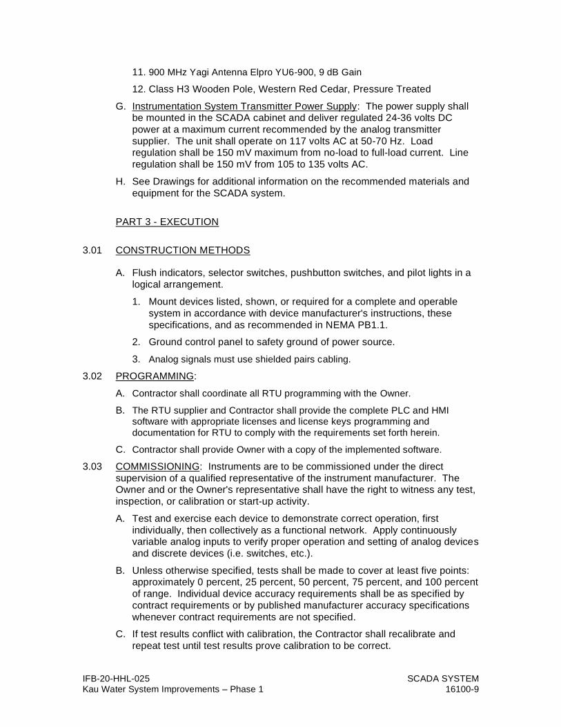
IFB-20-HHL-025 SCADA SYSTEM Kau Water System Improvements – Phase 1 16100-9
11. 900 MHz Yagi Antenna Elpro YU6-900, 9 dB Gain
12. Class H3 Wooden Pole, Western Red Cedar, Pressure Treated
G. Instrumentation System Transmitter Power Supply: The power supply shall be mounted in the SCADA cabinet and deliver regulated 24-36 volts DC
power at a maximum current recommended by the analog transmitter
supplier. The unit shall operate on 117 volts AC at 50-70 Hz. Load regulation shall be 150 mV maximum from no-load to full-load current. Line
regulation shall be 150 mV from 105 to 135 volts AC.
H. See Drawings for additional information on the recommended materials and
equipment for the SCADA system.
PART 3 - EXECUTION
3.01 CONSTRUCTION METHODS
A. Flush indicators, selector switches, pushbutton switches, and pilot lights in a
logical arrangement.
1. Mount devices listed, shown, or required for a complete and operable
system in accordance with device manufacturer's instructions, these
specifications, and as recommended in NEMA PB1.1.
2. Ground control panel to safety ground of power source.
3. Analog signals must use shielded pairs cabling.
3.02 PROGRAMMING:
A. Contractor shall coordinate all RTU programming with the Owner.
B. The RTU supplier and Contractor shall provide the complete PLC and HMI software with appropriate licenses and license keys programming and
documentation for RTU to comply with the requirements set forth herein.
C. Contractor shall provide Owner with a copy of the implemented software.
3.03 COMMISSIONING: Instruments are to be commissioned under the direct
supervision of a qualified representative of the instrument manufacturer. The Owner and or the Owner's representative shall have the right to witness any test,
inspection, or calibration or start-up activity.
A. Test and exercise each device to demonstrate correct operation, first
individually, then collectively as a functional network. Apply continuously variable analog inputs to verify proper operation and setting of analog devices
and discrete devices (i.e. switches, etc.).
B. Unless otherwise specified, tests shall be made to cover at least five points: approximately 0 percent, 25 percent, 50 percent, 75 percent, and 100 percent
of range. Individual device accuracy requirements shall be as specified by
contract requirements or by published manufacturer accuracy specifications
whenever contract requirements are not specified.
C. If test results conflict with calibration, the Contractor shall recalibrate and
repeat test until test results prove calibration to be correct.

IFB-20-HHL-025 SCADA SYSTEM Kau Water System Improvements – Phase 1 16100-10
3.04 TEST REPORT: Prepare a test report showing actual value, instrument value, 4-20 mA value (at the RTU) for each test, and range of the instrument. Each test
shall bear the signature of the contractor's representative who supervised the
tests and the manufacturer's representative. Three copies of these reports in
bound sets label "CALIBRATION DATA" are to be furnished to the Owner's
Representative.
3.05 ADDITIONAL START-UP SERVICES: The Contractor shall include an additional
two days of programming time and the cost for the RTU’s programmer to visit the site for one of the days in the bid. This time may be used at the discretion of the
Owner for additional programming, changes, and/or training. This time is over
and above the work necessary to provide a complete and operable system.
3.06 GUARANTEE: The SCADA system, equipment, materials, and associated items
shall be guaranteed against defective parts and operation due to faulty material
or workmanship during the period of one year following acceptance and final
payment by the Engineer. The Contractor shall make all repairs or replacements necessary to accomplish the required performance within the time specified by
the Engineer and agreed to by the Contractor.
3.07 MEASUREMENT AND PAYMENT
A. General: No separate payments will be made for the work covered by the
separate section of the 16000 series of these specifications. All costs in
connection with furnishing and installing of the various items in accordance with standard practice, the details shown on the drawings and in accordance
with these specifications, shall be included in the lump sum price of which the
item is a part.
B. Compensation: Payment of the furnishing and installing of equipment will be made at the lump sum price bid of which the item is a part and shall be full
compensation for all work in accordance therewith, complete and finished in
accordance with the drawings and specifications.
END OF SECTION