Technical Specifications and General Guidelines for...
31
Specifications/Datasheets Hydrocarbon Detection System for Petroleum Oil Installations 1 Technical Specifications and General Guidelines for Hydrocarbon Detection Systems at Petroleum Oil Installations Note: These are general specifications and guidelines for HC Detection Systems for Petroleum Oil Installations. The scope of this tender is limited to the following components of the system; 1. Supply of Point type HC Detectors/Sensors 2. Supply of Open Path type HC Detectors/Sensors (150 m range) 3. Supply of Open Path type HC Detectors/Sensors (60 m range) 4. Gas Calibration kit with hand held calibrators 5. Supervision of Installation & Commissioning 6. Supply of Liquid type HC Detectors Specifications/provisions relevant to the above scope of supply shall be applicable for this tender. Site execution works including any cabling, installation, control system, software, integration with existing terminal automation systems are not part of the scope of this tender.
Transcript of Technical Specifications and General Guidelines for...

Specifications/Datasheets
Hydrocarbon Detection System for Petroleum Oil Installations
1
Technical Specifications and General Guidelines for Hydrocarbon Detection Systems at Petroleum Oil Installations
Note: These are general specifications and guidelines for HC Detection
Systems for Petroleum Oil Installations. The scope of this tender is
limited to the following components of the system;
1. Supply of Point type HC Detectors/Sensors
2. Supply of Open Path type HC Detectors/Sensors (150 m range)
3. Supply of Open Path type HC Detectors/Sensors (60 m range)
4. Gas Calibration kit with hand held calibrators
5. Supervision of Installation & Commissioning
6. Supply of Liquid type HC Detectors
Specifications/provisions relevant to the above scope of supply shall be applicable for this tender. Site execution works including any cabling, installation, control system, software, integration with existing terminal automation systems are not part of the scope of this tender.
Specifications/Datasheets
Hydrocarbon Detection System for Petroleum Oil Installations
2
Table of Contents 1.0 Introduction Pg 3
2.0 Definitions & Abbreviations Pg 3
2.1 Definitions Pg 3-4
2.2 Abbreviations Pg 4-5
3.0 Standards & Codes Pg 6
4.0 System Implementation Methodology Pg 7
4.1 For New Petroleum Oil Installations Pg 7
4.2 For Existing Large Oil Installations Pg 7
4.3 Other Installations/Depots Pg 7
5.0 System Description Pg 8-16
6.0 Vendor’s Scope of Supply & Works Pg 16-17
7.0 Inspection, Testing & Commissioning Pg 17
7.1 Inspection Testing Plan Pg 17
7.2 Factory Inspection Test Pg 17-18
7.3 Installation, Testing & Commissioning Pg 19
7.4 Site Acceptance Test Pg- 20
7.5 Final Acceptance Test Pg- 20
7.6 Rejection Pg 20
8.0 Training Pg 21-22
9.0 Warranty Pg-22
10.0 Post Warranty Maintenance Pg 22-23
11.0 Delivery, Storage, Safety and Handling Pg 22
Typical System Configuration Pg-23
Annexure-1 Specifications for Point Gas Detectors Pg 24-25
Annexure-2 Specifications for Open Path Gas Detectors Pg 26-27
Annexure-3 Specifications for Portable Gas Detectors Pg 28
Annexure-4 Specifications for Ex-proof Horns Pg 28
Annexure-5 Specifications for Ex-proof Flash Lights Pg 29
Annexure-6 Specifications for Single Triad Cables Pg 30-31
Annexure-7 Specifications for Junction Boxes Pg 32
Annexure-8 Specifications for PLC Pg 33-40
Addendum Specification for HC Liquid Detection System Pg 41-45
Specifications/Datasheets
Hydrocarbon Detection System for Petroleum Oil Installations
3
1.0 Introduction:
1.1 This specification together with the attachments defines and covers the guidelines for Design, Engineering, Selection of Equipment, Equipment specification, Scope of work, Inspection & Testing, Installation and commissioning requirements complete with all accessories and materials for “Installation of IR Sensor based on-line Hydrocarbon Gas Detection system at various Petroleum Oil Installation of IOCL/BPCL/HPCL.
1.2 The gas detection system shall be installed in Oil Installations/Depots for Class-A
petroleum products. 1.3 All the items required for proper functioning and operation of the complete system
shall be furnished by the Vendor, even though not specifically called in the specification.
1.4 In the event of any conflict between specifications, codes and applicable standards etc, the vendor shall seek necessary clarifications from the purchaser before proceeding with manufacturing the item in question.
1.5 In case of conflict between standard specification and job specification, the latter
shall prevail 2.0 Definitions & Abbreviations 2.1 Definitions:
Plant Means IOCL/BPCL/HPCL’S installations as the case may be, in connection with construction and/or operation for which the equipment & services are to be supplied.
Equipment/ Services
Means equipment and or services but not limited to materials, equipment, fabricated products, software, drawings, certification and other documentation to be supplied.
Vendor Shall mean any person, firm or company having a purchase order for the supply of the hydrocarbon gas detection system or part of it to IOCL/BPCL/HPCL.
Alarm An audible and/or visible means of drawing attention of the operator in case of process or equipment abnormalities or malfunction from pre-defined set limits.
LEL Low Explosive Limit: The lowest concentration (percentage) of a gas or a vapor in air capable of producing a flash of fire in presence of an ignition source (arc, flame, heat).
Auto Ignition temperature
Lowest temperature of the substance at which it will spontaneously ignite in a normal atmosphere without an

Specifications/Datasheets
Hydrocarbon Detection System for Petroleum Oil Installations
4
external source of ignition,
Flammable Gas A flammable gas that burns when comes in to contact with heat or flame.
Flammable Liquids
Flammable liquids vary in volatility and have a flash point below 93 degree C.
Class-A Product
Flammable petroleum liquids having flash point below 23 degree C.
Flash point Flash point of a volatile liquid is the lowest temperature at which it can vaporize to form an ignitable mixture in air
ppm Part per million (ppm). It denotes one part per 1,000,000 parts, one part in 106, or a value of 1 × 10⁻⁶.
Hazardous Area Classification
Defined as a place where concentrations of flammable gases, vapors, or dusts occur. Electrical equipment that must be installed in such locations is especially designed and tested to ensure it does not initiate an explosion, due to arcing contacts or high surface temperature of equipment.
2.2 ABBREVIATIONS:
IOCL Indian Oil Corporation Limited
BPCL Bharat Petroleum Corporation Limited
HPCL Hindustan Petroleum Corporation Limited
GDS Gas Detection System
PLC Programmable Logic Controller
PHA Process Hazard Analysis
IR Infra red
IS Intrinsically safe
ISA Instrument Society of America
IEC International Electro-technical Commission
IEEE Institute of Electrical & Electronics Engineers
HAZOP Hazard and Operability Study
UL Underwriters Laboratory Inc
MCR Main Control Room
EN European Nation

Specifications/Datasheets
Hydrocarbon Detection System for Petroleum Oil Installations
5
EUC Equipment Under Control
ESD Emergency Shutdown System
DCS Distributed Control System
SIS Safety Instrumented System
E/E/P/S Electrical and Electronics Programmable Systems
ANSI American National Standards Institute
HMI Human Machine Interface
SIL Safety Integrity Limit
DIN Deutsches Institut Tur Normung eV
FM Factory Mutual
ATEX ATmosphères EXplosibles
CENELEC European Committee for Electrotechnical Standardization
TUV Technische Uberwarchungs Verein
NEMA National Electrical Manufacturers Association
CPU Central Processing Unit
I/O Input/ Output
UPS Un-interrupted Power Supply
FAT Factory Acceptance Test
SAT Site Acceptance Test
EMC Electro-magnetic Compatibility
MODBUS-RTU
PROTOCOL
Communication Protocol used for establishment of DCS-
PLC communication
RS-232/422 Standards on Serial Communication Protocol
TMR Triple Modular Redundant
QMR Quadruple Modular Redundant
MTBF Mean time between failure
MTRR Mean time to repair
NFPA National fire Protection Association
CSA Canadian Standards Association
VDU Visual display unit

Specifications/Datasheets
Hydrocarbon Detection System for Petroleum Oil Installations
6
3.0 Standards & Codes:
Applicable standards referred below shall be of the latest editions:
IEC-79 Electrical apparatus for Explosive Gas Mixture.
IEC-529 Classification of degree of protection provided by enclosures.
IEC-801 Electromagnetic compatibility for Industrial process measurement & control equipment
IEC-61508 Functional Safety of electrical/electronic/ programmable electronic safety related system.
IEC-61511 Functional safety – Safety instrumented system for the Process Industry.
IS-2146 Flameproof enclosures of electrical apparatus
IS-2147 Degrees of protection provided by enclosures for low voltage switch gears & control gears.
BS EN-50054 Electrical apparatus for the detection & measurement of combustible gases – General requirements & Test methods.
BS EN-50057 Performance requirements for Group II apparatus indicating up to 100% LEL.
EN 50270 Electrical apparatus for the detection and measurement of combustible gases, toxic gases and oxygen.
EN 50241 Specification for open-path apparatus for the detection of gases and vapors
DIN-50049 Document on material testing.
MIL-HDBK 217
Reliability prediction for Electronic Equipment
OISD-117 Fire Protection Facilities for Petroleum Depots, Installations, Pipeline Installation and Lube Oil Installations.
OISD-152 Safety Instrumentation for Process System in Hydrocarbon Industry.
OISD-163 Process Control Room Safety.
OISD-173 Fire Protection System for Electrical Installations

Specifications/Datasheets
Hydrocarbon Detection System for Petroleum Oil Installations
7
4.0 System Implementation Methodology:
Implementation of the Gas Detection system shall comprise of but not limited to the
following system components:
IR based Point/Open Path Gas detectors at the field.
PLC based system in Control Room for safe, reliable and effective
monitoring and control of safety and process parameters to safeguard
Installations.
All associated devices, equipment and accessories necessary for
implementation of integrated system for interfacing the above.
General guidelines for implementation of Gas Detection system for Oil installations will be as under:
4.1 For New Petroleum Oil Installations:
Control system of the gas detection system shall be SIL-3 certified PLC to meet the requirements of OISD-152 latest revision. In such case, specification of the control system shall be as per SIL-3 requirements for safeguarding.
Primary requirements of the subject system shall be for Safety Control and shall have capability for implementation of safety function related logics for Fire Suppressions systems, Foam systems, Start / Stop actions for the Pumps and Open / Close actions for the MOVs.
PLC system shall have capability for generating graphics, displays, historization, trending and alarms as minimum.
For all open contacts (NO) to the field, feature of line monitoring facility will be implemented to continuously monitor the health of field cables and provide alarm in case of any cable fault / cut.
4.2 For Existing Large Oil Installations Implementation of gas detection system will be implemented through PLC and MMI interface and in such cases, clause 4.1 shall be applicable otherwise gas detectors are to be hooked up with the existing PLC system as per approved design and implementation plan,
4.3 Other Installations/Depots: In this case, clause 4.1 or 4.2 will be applicable as per the system implementation
plans.

Specifications/Datasheets
Hydrocarbon Detection System for Petroleum Oil Installations
8
5.0 System Description: 5.1 Main objective of the Gas Detection System shall be to detect hydrocarbon gas
concentrations in Petroleum Oil Installations/Depots and initiate alarm or shutdown system as the case may be, at pre-defined levels to prevent any hazardous events and act as independent safety layers for mitigation of consequences to achieve overall process safety requirements of the plant.
Gas Detection system shall be designed to perform its function during normal, abnormal and design basis conditions.
Control system shall be based on open architecture system topology with fault tolerant network capabilities.
Gas detection system shall be based on the following and as per detailed scope of work:
Type of Gas Detectors/Sensors:
IR’ based integrated (sensor cum transmitter) point type gas detectors for
measurement, signal transmission and local monitoring of LEL levels in
application area.
`IR’ based Open Path detectors for measurement, signal transmission and
monitoring of LEL levels in application area.
Control System & System Description:
Control system of the Gas Detection shall be SIL-3 certified fault tolerant Programmable Logic Controller (PLC).PLC configuration shall be based on programmable system design to meet above compliance.
The control system shall be stand-alone, based on fail safe philosophy having
necessary hardware & software with graphics based MMI interface for installation in the Control Room. It shall be able to operate independently and its operation shall not be affected by failure of any other instrumentation system. The proposed system shall be engineered as one integrated control and safeguarding system with respect to operator presentation.
The system will generate alarm as soon as the LEL level in the field crosses the set level in either one sensor or more sensors. In alarm condition there will be an Audio-Visual Alarm in the Main Control Room to alert the Operator & the hooter should operate in the field to alert the field operator about the LEL Alarm level. The hooter in the field & the Electronic buzzer in the control room will stop on operating of Accept Push button installed on the control unit installed in the control room & the visual alarm should remain flashing till the LEL level is restored back to normal limits. When the LEL level in the field is in normal the flashing of alarm should become steady Alarm. The alarm
Specifications/Datasheets
Hydrocarbon Detection System for Petroleum Oil Installations
9
should be reset on operating of Reset Push button installed in the control room.
The GDS shall be micro-processor based configurable, expandable,
distributed, intelligent safety system providing gas detection, alarm signaling, notification and capable of extinguishing agent release, and/or deluge operation.
There will no separate monitoring panel for gas detection system.
Control system shall have the feature to measure the field signal below 4mA DC or above 20mA DC for configuration gas detectors various operating statues (normal, fault condition and gas detected condition etc.)
Each gas detection system may be individually interrogated from the field by unique tag name and appear in PLC as any other instrument complete with faceplate and tuning parameters.
Detectors in a particular zone in the field may be arranged in 2oo3 (two out of three) or any other voting logic as per the hazards and in such case system engineering should be made in such a way that inputs are terminated in the different input cards in order to enhancing the system reliability.
For zone-wise monitoring of gas detection system at the field level, all indications may have to be repeated at pre-designated location as per the execution plan. In such cases, no series connection of the gas detector and field indication is allowed. Vendor shall use either signal repeater at the control room or generate standard output signal from the PLC for generation of repeat signal for the local indicator,
Control system shall have capability to display process as well as system alarms on the console for operator’s attention and action. Alarms shall appear immediately on the operator console as and when they occur on priority basis. It shall also be possible to display summary of all alarms in the sequence of their occurrence and shall disappear from display only when they are acknowledged and cleared.
Historization of the alarm conditions shall be maintained in the data base for alarm history for a minimum period of one year and the alarm display and print out shall list the following for each alarm as a minimum :
Date and time of occurrence
Point identification (i.e. Tag number) & description
Type of alarm
Time of acknowledgement
Time of return to normal
Serial number of alarm in the sequence of occurrence

Specifications/Datasheets
Hydrocarbon Detection System for Petroleum Oil Installations
10
Vendor shall supply necessary software, in this regard for event sequencing and logging.
The PLC will have high noise immunity in order to ensure safe and reliable operation when subjected to electrical radio frequency interference and electro-magnetic disturbances expected in a plant. The surges withstand capacity for input / output modules shall be as per IEEE Standard 472.
PLC I/O cards shall have facility to detect wire open condition whenever normally open inputs (close on alarms) are considered.
All I/O circuits shall be provided with galvanic isolation or optical isolation and each I/O shall be protected against reversal of polarity of the signal.
Each output shall be short-circuit proof and protected by fuse. Visual indication of fuse down must be provided for each output
In addition to digital Pulse input / output, PLC shall be able to cater for analog inputs/output signals of 4-20mA DC, 1-5 V DC , 0-10 V DC.
All output cards shall have output contact rating of 24 VDC 2 Amp inductive to drive solenoid valves, MCC controls though interposing relays.
Field Contacts subject to 24 V DC or less shall be potential free, gold plated dry contacts.
All networking components shall of Industrial grade.
The control system shall have well laid down procedure for on-line
maintenance and faulty module replacement.
The control system shall have features for interfacing with Owner’s third party system (DCS/PLC) through serial (RS232C/422 output) communication with `MODBUS’ protocol and to provide isolated analog signal/hardwired contact from controller for owner’s third party system as specified in the detailed BOM (Bill of Material).
Accessories:
5.1 Other essential items, accessories, interface modules, pneumatic hooters,
electronic buzzer, junction boxes & panels at field as well as control room
required for integration of field sensors with the control system including
cabling.
5.2 Gas detection system is required for continuous monitoring of combustible
hydrocarbon gas where gas/vapor leaks can happen over a widely dispersed area and it shall be suitable for installation in Petroleum Oil installations.

Specifications/Datasheets
Hydrocarbon Detection System for Petroleum Oil Installations
11
5.3 Intended gas detection system shall be capable to detect class A product like petrol & naptha and most hydrocarbon gases (C5 to C12) and performance shall be not be affected by oil mist, glycol, water vapor and salt water.
5.4 Point type Gas detectors shall have infra red based sensor and transmitter
unit powered through 24VDC supply. 5.5 Open path Combustible Gas detectors shall be based on Infra red technology
having a transmitter and receiver unit both powered by 24VDC. 5.6 Gas detector housing material shall be metallic suited for corrosive saline,
high humid environment 5.7 Gas Detectors shall be fully tropicalised and all atmospheric vents fitted with
bug screens wherever applicable. 5.8 All enclosures for electrical equipment shall be suitable for use in hazardous
area as per facility hazardous area classification & vendor shall submit valid test certificates issued by CIMFR/PESO. Flameproof enclosure which are manufactured outside India & certified by accredited international authorities shall also have approval of PESO, India.
5.9 GDS shall be designed in such a way that it shall meet requirements of OISD
117 (October 2010) 5.10 The gas detectors shall be SIL-2 certified from accredited international
certification agency. 5.11 No operational or start-up override switches are permissible. 5.12 All field mounted devices including gas detectors shall be provided with
canopy/sunshades for protection against rain and water. 5.13 All gas detectors shall be calibrated at 20% and 60% of LEL or equivalent to
LFL meter as the case may be. 5.14 Vendor may note that in no case, gas panel based control system shall be
considered for implementation of Gas Detection system. 5.15 Vendor may accordingly refer the BOM for location-wise selection of the
appropriate Control System. 5.16 Power Supply Requirements: 230 V/110V (± 10%), ±50Hz (± 3%) AC UPS Power shall be made available at
the Control Room as a single point source by the owner. Further power distribution to marshalling and other cabinets and voltage distribution to field devices shall be designed, supplied & installed by the vendor. Vendor shall indicate the maximum and normal operating power loads along with the bid.
Specifications/Datasheets
Hydrocarbon Detection System for Petroleum Oil Installations
12
AC to DC power supply units shall be provided in each cabinet. It shall be ensured that power supply units are redundant failure of one will not affect the operation of the PLC system. All power supply units (AC to DC) shall be approved for SIL-3 application having features of dual built-in over voltage protection to comply safety requirements of IEC-65108/DIN V 19250/VDE V 0801 standards. It shall comply to redundant parallel operation with under voltage alarm and optimum protection against continuous overload and short-circuiting. Power supply units in redundant configuration shall be designed for maximum load of 70%.
Bidder shall also include miniature circuit breakers (MCB) for AC supply to
each power supply units and sub-distributions within the system. Bidder shall ensure that isolation facilities are provided for DC sub-system so that maintenance work can be taken up during operation stage without causing and disturbance to other sub-systems and devices.
Power distribution network shall be designed in such a way that single point
failure shall not cause tripping of the total system. Each distribution point shall be provided with a separate MCB of power rating for isolation of the system
Separate signal ground will be provided for circuit ground of instruments, drain
wires of signal cable shield etc. Gas detectors shall be grounded by the OEM’s recommendations. For signal ground, a grounding bus bar of 6mm thick cooper (insulated from panel structure) will be provided which shall run the entire panel at either end. Bus bars shall be provided with grounding terminals at either end. All instrument housing capable of carrying current shall be grounded to panel structure having provisions for earthing lugs. Irrespective of above, Bidder shall indicate the earthing philosophy of their offered systems including field devices and include in their offer including provisions earthing lugs, earthing cables etc. including final connectivity. Provisions of earth pits will be under owner’s scope for which bidder shall indicate the requirements.
Monitoring of status of Main AC as well as DC power supply units hall be included in the PLC as a minimum requirements.
5.17 Environmental Conditions:
The system shall be designed to operate under following ambient conditions: Amb. Temp. (Outside): 65°C.(maximum)
Design Temp. (Air Cooled Control Room): 25°C.
Relative Humidity (non-condensing): 100%
Gas detection Monitoring system (PLC) will be located in air-conditioned
control room located in safe area of ISA S71.04, G3 classification. Normal
operating condition will be 25±5 deg. C and 80±10% RH.

Specifications/Datasheets
Hydrocarbon Detection System for Petroleum Oil Installations
13
The system shall continue to operate in case of HVAC upset conditions and
when temperature may fall to 9°C or rise to 50°C with corresponding humidity
vary from 20% to 90% (non-condensing).
5.18 Hazardous Area Classification & Environmental Protection
Instruments located in hazardous area shall be certified to meet or exceed the electrical hazardous area classification . The field instruments, equipment and accessories etc. shall be flame-proof and suitable for hazardous area classification of Zone-1, Gr. IIA/B, T3 or better. Similarly all field instruments, equipment and accessories etc shall be weather-proof to IP65/67 as the case may be. Instruments & all enclosures for electrical enclosures certified for use in hazardous area shall have certification for use by accredited authority like FM. CENELEC, BASSEFA, ATEX and approved by PESO.
5.19 Cabling Philosophy:
Signal cables for gas detectors shall be single triad and 8-triad for multi-core cables. It will be of stranded copper conductor of minimum 1.5mm2 or higher according to power loading calculations.
There shall not be any cable joints for signal, alarm and control cables.
All main multi-core / multi-pair cables having more than three cores shall have a minimum of 20% spare cores / pair.
Power distribution network shall be designed in such a way that single point failure shall not cause tripping of the total system. Each distribution point shall be provided with a separate MCB of power rating for isolation of the system.
All the above ground cables shall be laid in galvanized metallic cable trays. Underground cables shall be laid in armored HDPE conduits as per ASTM F2160 (Standard Specification for Solid Wall High Density Polyethylene Conduit)
All cables inside the control rooms shall be properly dressed and routed in GI perforated trays under false flooring, which will be supplied & installed by the vendor. Trays shall have capacity to lay the cable in single layer with 20% spare capacity for future use. Separate cable route and trays shall be used for signal or power inputs in control room and routing of cables shall be planned within control room/ rack room to ensure ease of cable installation and to prevent the interference among the cables. Separation with electrical cables (LT and HT both) shall be maintained as per API guidelines or a minimum of 1500 mm.
5.20 Junction Box:
Specifications/Datasheets
Hydrocarbon Detection System for Petroleum Oil Installations
14
Junction boxes in hazardous area shall be certified flameproof wherever flameproof instruments are connected to junction boxes as the case may be. Junction boxes shall be weather-proof to IP65/67.
In general separate junction boxes shall be used for the 4-20mA DC signals, contact signals, interlock & shutdown signals and power supply to various instruments etc.
Each JB shall be provided with 2 multi-cable entries with one plugged with weatherproof plugs. One junction box shall be connected to one multi-cable only. Plugs shall also be flame proof for flameproof junction boxes.
All cable glands shall be provided with PVC shrouds to prevent ingress of moisture and rain water inside the junction boxes.
The junction boxes in the field as well as in local panel shall be provided with sufficient number of terminals to terminate all the pairs of multi-cable (including spare pairs) and shields of individual pairs as applicable. Junction boxes shall have separate external terminal for accommodating earthing wires up to 10sqmm.
5.21 Cable Glands
All cable glands shall be double compression type, nickel-plated and weather proof and flameproof suitable for installation in an area classification of IEC Zone I Gas Group IIC. The cable glands shall be provided with PVC hood. Cable glands shall be suitable for cable dimensions with +/- 2mm tolerance. The plugs and adaptors shall also be weather proof and flameproof suitable for installation in an area classification of IEC Zone I Gas Group IIC.
5.22 Audio-Visual Alarm:
Acoustic and visual alarms shall be automatically activated from Gas detection control unit located in Control Room. On receipt of signal from detectors the tone used for gas alarm horns shall be clearly identifiable and different from the tones used for other alarms (e.g. fire alarm, plant emergency alarm etc). Audible alarms shall be designed for designated zone as per site specific requirements and ensure full coverage of the area. Audible alarms at site may be configured in redundant mode, if different path configurations are being used for multiple detectors.
For visible alarms, flashing beacons shall be provided for alarms in the field. And these shall be provided with blue lenses for flammable gas and provide

Specifications/Datasheets
Hydrocarbon Detection System for Petroleum Oil Installations
15
required light output in case of alarm situation so that operating personnel can detect it easily. Xenon type strobe tubes shall be used.
Audio-visible alarm devices of a particular zone shall be located near to associated gas detectors cluster and can be identified from a distant position.
5.23 Portable Gas Detector:
The portable gas detectors shall be supplied complete with its controller, audio-visual alarm and shall be suitable (intrinsically safe) for use in hazardous area specified. Such units shall be certified by BASEEFA, CENELEC, FM, PTB, CMRI etc and approved by PESO. These units shall be supplied with rechargeable batteries and 230V, 50Hz AC battery charger. Adequate number of battery charger/number of points per charge shall be provided based on quantity of such portable units. These units shall be supplied complete with its accessories like carrying case Kit, calibration Kit etc.
5.24 Portable Calibrator:(optional)
One portable purge calibrator for Hydrocarbon consisting of a volume bottle containing a known gas / air mixture, a pressure regulator, a flexible hose and adaptor cap (to fit the sensing head) shall be supplied to enable calibration of the sensors in the field without dismantling them. Material of constructions will be of SS316 as a minimum.
Vendor shall ensure necessary and sufficient supply of gases for calibration of all sensing heads at 20% and 60% LEL levels at least twice during commissioning period and subsequent period of one year from final acceptance test.
5.25 All field devices shall be certified for installation conforming to the corresponding electrical area classifications. Solenoid valves, if any for field shall be suitable for 24V DC operation.
5.26 Bidder shall offer and quote standard spares with unit rate validity of 2 years,
if any required for maintenance and calibration of the offer gas detector system. However, commissioning spares shall be under the scope of vendor.
5.27 Bidder shall offer and quote special tools & tackles with unit rate validity of 2
years, if any required for maintenance and calibration of the offer gas detector system.
6.0 Vendor’s Scope of Supply & Works: (Please refer BOQ)
The Vendor shall be responsible for all types of Civil, Mechanical, Electrical, & Instrumentation work including. The provision and installation of the Gas Detection System by the Vendor shall be based on site specific requirements but not limited to the following & shall consist of:

Specifications/Datasheets
Hydrocarbon Detection System for Petroleum Oil Installations
16
a) Design, Engineering, Manufacturing & Supply, Installation, testing, Calibration & Commissioning of all the components and accessories of the Gas Detection system as per the specification including customized site specific Gas Detection Control system complete with gas detection panels etc. in the Control Room/operator cabin.
b) Supply, Installation & Commissioning field mounted gas detectors.
c) Supply of handheld universal HART calibrators (optional).
d) Portable calibrators for the gas detection system.
e) Supply, Installation & Commissioning zone-wise field mounted panels depending upon the specific site requirement where applicable (Owner to specify) with individual gas detectors indication, status with Acoustic hooters & Audio-visual alarms facility as detailed in the specification.
f) Supply & Installation of Local Junction Boxes complete with necessary cable glands.
g) Supply, laying, dressing and termination of all required signal, power
& control cables, interface cables in the field, between field and
Control Room, as well as at Control Room.
h) Preparation of drawings/documents, procurement, installation , cabling, dressing, supply of cable tray and erection, supply ind installation of supports for cable tray, Cable dressing, termination, testing, calibration, loop checking and commissioning of all gas detectors and controls with their accessories, installation material etc., including supply of commissioning spares, arranging all types of equipment for testing, calibration, as required for “ Installation of IR Sensor-cum-transmitter based on-line Gas Detection system.
i) Supply of Manuals containing Operating and Maintenance procedures, as built drawings, technical documents & approvals in Hard copies & CD form.
j) Supply of all software on CD along with required software licenses.
k) Factory acceptance test as per clause 7.2 of the specification.
l) Site acceptance test as per clause 7.4 of the specification.
m) Commissioning of the system.
n) Training of the buyers personnel on functional, operational & routine maintenance aspects of the system.

Specifications/Datasheets
Hydrocarbon Detection System for Petroleum Oil Installations
17
o) All civil, mechanical, electrical & instrumentation work required for completion of the job.
p) Supply of portable gas detector for field use.
Any other component and software required for completion and commissioning of the system shall be supplied & installed by the vendor except the items mentioned under the Owners scope under clause 5.0.
Execution of work may also involve working in running plant(with the presence of explosive gas mixtures) /control room, All necessary precautions/ arrangements for carrying out any activity in the running plant /control room including strict compliance necessary for strict fire & safety rules shall be adhered by the vendor for safe execution.
7.0 Inspection, Testing & Commissioning The bidder shall submit their QAP for approval as per the scope of supply for Third Party Inspection. Only those provisions related to scope of supply shall be applicable. 7.1 Inspection Testing Plan 7.1.1 Vendor shall submit their own testing, installation, commissioning and
acceptance procedure including purpose of test, test definition of input, procedure, results, expected and acceptance criteria.
7.1.2 For software, it shall include details of the method, list of test sequence of
execution, results expected and acceptance criteria. 7.1.3 The testing and acceptance of the system shall be carried out on the mutually
agreed procedure and criteria based on these guidelines and vendor’s standard procedures.
7.2 Factory Inspection Test (FAT) -The bidder shall submit their QAP for
approval as per the scope of supply for Third Party Inspection. Only those provisions related to scope of supply shall be applicable
7.2.1 Vendor shall arrange Factory Acceptance Test in presence of Owners
representative/ Third Party Inspection (TPI) agency approved by the owner. The cost of performing all tests shall be borne by the vendor including Third Party Inspection Charges.
7.2.2 During FAT, Vendor shall test and demonstrate for the following minimum
hardware and software functional integrity of the system. No material or equipment shall be transported until all required tests have been successfully completed and the material / equipment have been certified “Ready for Shipment” by the Owner/TPI.
7.2.3 FAT shall be conducted by interconnecting all sub-systems, as close as
possible to the total integrated system. Testing shall be systematic, fully
Specifications/Datasheets
Hydrocarbon Detection System for Petroleum Oil Installations
18
functional test covering of all hardware and software in the presence of Owners representatives/TPI.
7.2.4 Before commencement of FAT, vendor shall conduct pre-FAT to ensure that
all components are functional in accordance with the specification for each type of test. A test report shall be submitted for Owners’ review within two weeks of completion of the test.
Vendor shall also notify the Owner at least 2 (Two) weeks prior to factory acceptance test. Following minimum tests shall be part of FAT: General: Visual and mechanical/dimensional testing High voltage and insulation testing Calibration report of all Gas detectors Certificate from a statutory body for intrinsic safety/flame proof and
weather proof for all field mounted instruments, equipment and enclosures.
Functional testing: Simulation of each input & output to verify status and system
response. Checking of all power and control wiring for continuity. Functional checking of gas detectors with liquid HC in conjunction with
the controllers, printers, annunciations etc. Checking of all devices and system scan time. System diagnostic checking for the total control system. Checking of the testing of the software. Graphics checking. Checking of output status on processor failure. Checking of first-out alarm generation. Simulation of power failure and system restart auto boot-up of system
configuration and program after power restoration. Actual simulation testing using liquid hydrocarbon.
7.2.5 Owner also reserves the right to involve and satisfy himself at each and every
stage of testing and shall be free to request specific tests which are although not listed in this specification, but agreed as a part of factory acceptance test procedure.
7.2.6 Vendor to note that any acceptance or exemption of inspection/ testing of any
equipment shall in no way absolves vendor’s responsibility for delivering the equipment meeting all the specified requirements. Schedule of FAT shall be included in the vendorr’s proposal.

Specifications/Datasheets
Hydrocarbon Detection System for Petroleum Oil Installations
19
7.2.7 Vendor shall not replace any component / module / subsystem unless it has failed and a log of such failures shall be maintained during FAT. If a malfunction of module / component in a subsystem repeats, the test shall be terminated and Seller shall replace the faulty component module.
7.3 Installation, Testing & Commissioning
Vendor shall depute their team for installation of the entire system in accordance to the detailed scope of work including cable laying, testing and calibration checking of the field sensors and commissioning of the system.
Before installation, vendor shall thoroughly check all equipments for completeness and proper functioning. Vendor must initiate the remedial action, in case unsatisfactory operation of any item is observed, with intimation to Engineer-in-charge.
7.4 Site Acceptance Test (SAT) )- NOT Applicable
7.5 Final Acceptance Test - Not Applicable 7.6 Rejection
Vendor shall make his offer in detail with respect to every item and list conformities. Any offer not conforming to this shall be summarily rejected
8.0 Training
Vendor shall impart training to site personnel for routine operation & preventive maintenance of the gas detection system. The training shall be imparted at owner’s site for minimum two days immediately after commissioning.
Vendor shall also provide training free of charge (15 persons in two batches) to the engineering/operation/maintenance staff at their works. The training shall include but will not be limited to the following: Training on the operation of the entire systems as per functional
requirement including start up and shut down of the system. Maintenance training on the hardware & software being supplied. The different hardware components to be supplied by the vendor. Calibration and maintenance aspect of the field sensors.
Details of training plan will be finalized before commencement of supply.
9.0 Warranty

Specifications/Datasheets
Hydrocarbon Detection System for Petroleum Oil Installations
20
Vendor shall offer performance guarantee for satisfactory and trouble free operation of the entire Gas Detection system for a minimum period of 1 year from the date of commissioning of the system excluding following conditions:
a) Point Gas Detectors shall have 5 years warranty after commissioning.
b) Open Path Detectors shall have 2 years warranty after commissioning
Vendor shall be fully responsible for the manufacture in respect of proper design, quality workmanship and operation of all the equipment, accessories, etc. supplied by the vendor during warranty period and it shall be obligatory on the part of vendor to modify and/or replace any hardware and modify the operating, application and diagnostic software free of cost, in case any malfunction is revealed even during on-line operation after taking over by the owner within the warranty period. The Vendor shall repair any defect or replace any defective part during the guarantee period within two weeks of receiving such information from the owner.
10.0 Post Warranty Maintenance: Not Applicable
11.0. Delivery, Storage, Safety and Handling All components of Gas Detection system shall be shipped to the job-site in original manufacturer’s shipping containers. The storage, safety and handling of systems and components before handing over to the owner shall be the responsibility of the vendor

Specifications/Datasheets
Hydrocarbon Detection System for Petroleum Oil Installations
21
Point type Infra Red Gas Detectors: Annexure-1
Sl No. Features Requirements
1 Sensor type Infrared sensor technology based explosion-proof
Gas sensor with transmitter
2 Principle of operation Multi-beam, dual compensated, non focusing
infrared absorption. Temperature compensation
shall be in-built.
3 Function Shall be able to detect hydrocarbon gases in the
range of 0-100% LEL
4 Gas Detection Configurable library having Methane, propane,
propylene, Ethane, Butane, Hexane, Pentane &
Benzene/R-LNG, covering Hydrocarbons (from
C1-C12)
5 Calibration Factory calibration at Methane or Propane
6 Range 0 to 100% LEL.
7 Construction Flameproof, 316SS body with dust/weather
protection for outdoor installation. No external
terminal box shall be provided for further cabling
(flying leads are not acceptable).
8 Optical performance Correct operation unto 75% obscuration, the same
shall be configurable with facility for dirty optics
warning. Provision (heated optics) for detectors to
be made to avoid condensation.
9 Input Power 24V DC nominal (18-30V DC)
10 Output: Choice of output mode shall be optional as per the following:
a) With `HART’ protocol 3-wire system, Linear 4-20mA DC (isolated/non-
isolated) rated at 600 ohms loop resistance at 24V
DC + HART.
Configurable detector fault signal (0 mA), beam
blockage, maintenance signal at 23.2 mA over
range etc.
Potential free contact output for LEL alarm.
b) With Alarm Relays 3-wire system, Linear 4-20mA DC (isolated/non-
isolated) rated at 600 ohms loop resistance at 24V
DC.
Alarm Relays: Two alarm relays, one fault relay SPDT; user programmable/pre-set. Relay contact will be suitable for 5A 230 VAC/ 5A 30 V DC.
11 Overall Accuracy Better than +/- 3% of LEL
12 Repeatability +/- 2% FSD
13 Zero drift 2 % FSD per year maximum.
14 Response time 90% of gas reading (without filter unit). in between
10-12 seconds
Specifications/Datasheets
Hydrocarbon Detection System for Petroleum Oil Installations
22
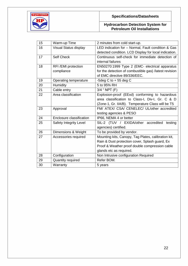
15 Warm-up Time 2 minutes from cold start-up.
16 Visual Status display LED indication for – Normal, Fault condition & Gas
detected condition. LCD Display for local indication.
17 Self Check Continuous self-check for immediate detection of
internal failures
18 RFI /EMI protection
compliance
EN50270:1999 Type 2 (EMC- electrical apparatus
for the detection of combustible gas) /latest revision
of EMC directive 89/336/EEC.
19 Operating temperature -5deg C to + 55 deg C
20 Humidity 5 to 95% RH
21 Cable entry 3/4 “ NPT (F)
22 Area classification Explosion-proof (EExd) conforming to hazardous
area classification to Class-I, Div-I, Gr. C & D
(Zone-1, Gr. IIA/B). Temperature Class will be T5
23 Approval FM/ ATEX/ CSA/ CENELEC/ UL/other accredited
testing agencies & PESO
24 Enclosure classification IP66, NEMA 4 or better
25 Safety Integrity Level SIL-2 (TUV / EXIDA/other accredited testing
agencies) certified.
26 Dimensions & Weight To be provided by vendor.
27 Accessories required Mounting kits, Canopy, Tag Plates, calibration kit,
Rain & Dust protection cover, Splash guard, Ex
Proof & Weather proof double compression cable
glands etc as required.
28 Configuration Non Intrusive configuration Required
29 Quantity required Refer BOM.
30 Warranty 5 years

Specifications/Datasheets
Hydrocarbon Detection System for Petroleum Oil Installations
23
Open Path Gas Detector Annexure-2
Sl No. Features Requirements
1 Sensor type Line of Sight Infra red absorption technique
(xenon flash lamp) having field replaceable
transmitter and receiver units
2 Gas Detection Configurable library having Methane, propane,
propylene, Ethane, Butane, Hexane, Pentane &
Benzene/R-LNG covering Hydrocarbons (from
C1-C12)
3 Range 0 to 5 LEL meter or better.
4 Operating distance 5 to 120 meter. Range selection shall be based
on actual operational requirements.
5 Operating voltage 24V DC nominal (18-32V DC)
6 Output: Choice of output mode shall be optional as per the following:
a) With `HART’ protocol Linear 4-20mA DC (isolated/non-isolated) rated
at 600 ohms loop resistance at 24V DC + HART
Configurable detector fault signal (0 mA), beam
blockage, maintenance signal at 23.2mA over
range etc.
b) With Alarm Relays 3-wire system, Linear 4-20mA DC (isolated/non-
isolated) rated at 600 ohms loop resistance at
24V DC.
7 Modbus Interface
(Optional)
Compliant to RS-485 protocol. Vendor to indicate
max no. of detectors that can be multi-dropped
with max. cable length.
8 Construction Flameproof, 316SS body with dust/weather
protection for outdoor installation. Terminal box
shall be provided for further cabling (flying leads
are not acceptable).
9 Accuracy ±0.25 LEL-meters or ±10% of applied gas
concentration, whichever is greater.
10 Displacement/ misalignment
tolerance
Shall have in-built sensor system for transmitter
& receiver alignment.
11 Warm-up Time 1 minute for transmitter. 30 seconds for receiver
from power-up when correctly aligned.
12 Sensitivity checking By placing test gas film in front of the receiver.
13 Field Alignment By local digital display and adjustable mounting
arms.
14 Local display LED indication for – Normal, Fault condition &
Gas detected condition. Local LCD Display for
indication.

Specifications/Datasheets
Hydrocarbon Detection System for Petroleum Oil Installations
24
15 Self Check Continuous self-check for immediate detection of
internal failures
16 RFI /EMI protection Shall comply performance verified in accordance
with EN 50241-1 and EN 50241-2.and
performance criterion as defined in latest revision
of EN 50270.
17 Operating temperature -5 deg C to + 55 deg C
18 Humidity 5 to 95% RH
19 Repeatability Better than +/- 3% of FS.
20 Cable entry 3/4 “ NPT (F)
21 Area classification Explosion-proof (Eexd) conforming to hazardous
area classification to Class-I, Div-I, Gr. C & D
(Zone-1, Gr. IIA/B). Temperature Class will be
T5
22 Enclosure classification IP66 or better
23 Approval FM/ ATEX/ CSA/ CENELEC/ UL/other accredited
testing agencies & PESO
24 Safety Integrity Level SIL-2 (TUV / EXIDA/other accredited testing
agencies) certified.
25 Power Consumption
Transmitter & Receiver
Vendor to specify.
26 Dimensions & Weight To be provided by vendor
27 Accessories required Mounting kits, detector alignment & calibration
kit, cell etc. Rain & Dust protection cover, Splash
guard, alignment & mode selection kits, Junction
box with terminals as required. Mounting bases
and Ex Proof & Weather proof double
compression cable glands etc as required.
28 Warranty 2 years.
29 Quantity required Refer BOM.

Specifications/Datasheets
Hydrocarbon Detection System for Petroleum Oil Installations
25
Portable Gas Detector Annexure-3
Sl No. Features Requirements
1 Use Portable detector with carrying case for
generation of audio-visual alarm at pre-set value
along with digital indication for LEL & Oxygen
(O2) levels simultaneously.
Display shall be safe illuminating/back-light digital
display.
2 Range Combustible gases: 0-100% LEL
O2: 0-25% By Volume
3 Area Classification Shall be suitable for use in Class-I, Division-I,
Group A & B. Vendor to provide necessary
certification.
4 Protection Atleast IP-55
5 Sampling Shall be fitted with integral motorized pump with
audio/visual low flow alarm. Option should be to
change over from motorized pump mode to
diffusion type.
Accessories shall include 10ft long sampling
hose and sampling probe be fitted with quick
connect. The probe shall be non-conductive and
flexible with moisture barrier.
6 Alarm 85 decibel audible alarm at 300cm rapid red
flashing visual alarm with vibration for fault, gas
alarm and warning indication. Two levels of
alarms for each gas sensed. Set points
adjustable over entre range.
7 Supply Re-chargeable battery should be suitable for
minimum 8 hrs. duration (with pump). Charger
operable with 230V AC, 50Hz shall be supplied
along with each instrument.
8 Sensor Life Atleast 3 years for hydrocarbon sensor and one
year for O2 sensor.
9 Calibration Frequency shall be at least 6 months
10 Accuracy ±0.2% of measured value.
11 Resolution Combustible Gas: 1% LEL
O2:0.1% by Volume
12 Response time 90% of measured value with in 30 sec.
13 Approval Intrinsically safe for use. Approval by PESO
14 Warranty 3 years except one year for O2 sensor
17 Other details Vendor to provide

Specifications/Datasheets
Hydrocarbon Detection System for Petroleum Oil Installations
26
Junction Box Annexure-7
Sl No. Features Requirements
1 Material of JB Cast Aluminum Alloy (LM6)
2 Mounting Outdoor , Hazardous area
3 Enclosure Industrial , Explosion proof as per IS-2148
4 Ambient Temp 0 to 60 Degree C.
5 Colour Light grey , Epoxy coated , as per shade 631 of
IS- 5
6 Terminals Spring loaded. Vibration proof. Clip on type
7 Construction Junction boxes shall have doors which shall be of
hinged type and these shall be fixed with SS or
cadmium plated countersunk screws
Terminals size Minimum 2.5 sq.mm
8 Terminal Numbering Required, suitable for 2.5 sq.mm conductor
9 Dimensions Overall : 355 mm X 385 mm ( approx)
10 Cable Entry Bottom & side , Main cable :1 1/2:” NPT(F) or as
per requirement & branch cable entry : 12/16 nos
½ “ NPT(F)
11 Mounting Accessories Required
12 Earthing lugs one inside & one outside (Size: M6)
13 Tag Plate Required
14 Plugging of entry ports Blind plugs shall be provided to block all idle
entries. The entry points shall be plugged by PVC
caps during transportation.
15 Tag Numbers As Specified
16 Make/Model No. Bidder to Specify
17 Quantity As Specified

Specifications/Datasheets
Hydrocarbon Detection System for Petroleum Oil Installations
27
Annexure-8
1.0 PLC: Not Applicable

Specifications/Datasheets
Hydrocarbon Detection System for Petroleum Oil Installations
28
HC Liquid Detection System: Addendum
Sl No. Features Requirements
1 Brief Description Design & Engineering, Supply, Testing, Installation and
Commissioning of Hydrocarbon Liquid Leak Detection
System.
2 Scope of Work Design, Engineering, Fabrication and Supply of all the
components of Hydrocarbon Liquid Leak Detection
System as per the specification.
Installation of the Hydrocarbon Liquid Leak Detection
System. In the field as well as in the Control Room.
Supply and installation of all required signal cables,
power cables, interface cables & junction boxes from
field to Main Control system in the control room.
Common audible/visual alarm fat Main Control Room.
Supply of Manuals containing Operating and
Maintenance procedures, as built drawings, technical
documents & approvals in Hard copies & CD form.
Supply of all software on CD along with required
software licenses.
Factory acceptance test specification.
Site acceptance test.
Commissioning of the system.
Supply of special tools & tackles, testing instruments
etc.
On-site Training of the buyer‟s personnel on
functional, operational & routine maintenance aspects
of the system.
All civil, mechanical, electrical & instrumentation work
required for completion of the job
Any other component and software required for completion and commissioning of Hydrocarbon Liquid Leak Detection
System shall be supplied & installed by the vendor. 3 Principle of
operation
To detect hydrocarbon liquid floating on water or spread over
flat surface
4 System
Configuration
Detection system shall comprise of field sensors directly
connected to Master Control system to be located at the
Control Room. All necessary interface units, accessories,
connectors and required cable will be part of the total system.
The system shall be used for early detection of hydrocarbon
spill or build-up and monitoring purposes (on-off action) and
provide audio-visual signal for operator’s alert The system
shall have the following features::

Specifications/Datasheets
Hydrocarbon Detection System for Petroleum Oil Installations
29
Control system shall be as a minimum, able to monitor
6 field sensors without any other interface units.
Typical distance between control room and field will be
1km or less.
With interface units, the system shall have capability
to connect 6x6 (36) field sensors as a minimum in
networking configuration.
The system shall have RS232/RS485/ MODBUS
connectivity to interface with client’s DCS/PLC/PC
based system.
Necessary isolators/barriers shall be part of the
system to ensure intrinsic safe operation of the
system. Generally, control will be located in safe area.
Bidder shall submit typical configuration drawing for owner’s review.
5 Field Sensor Shall be based on high frequency electro-magnetic absorption
or change in resistance technique.
Sensors will have min 100 mm active length encased in PVC
with static charge reduction additive. Associated jacked
connecting cables will be fuel resistant,
6 Sensor response
time
With-in 5 seconds for detection of MS, Naphtha, Aviation Fuel
& Diesel.
7 Sensor Life 3-5 years in continuous outdoor operation.
8 Sensor checking
& testing
Will generate instantaneous alarm condition on immersion in
HC liquid. Alarm condition will re-set on cleaning (free of HC)
and drying of the sensor.
9 Master Control
Station
To detect alarm condition of any of the probes and provide
audio-visual annunciation.
It shall have the following features as a minimum:
Capable of tracing 36 independent sensors.
Fully microprocessor based system having LCD
information panel and dedicated LED status lights for
monitoring, service, leak and fault condition.
for last 1000 events.
Non-volatile Password protected set-up.
Event logging memory for event history, set-up and
network configuration.
Continuous self-check for immediate detection of
internal failures
Necessary Rs-485 port for networking.

Specifications/Datasheets
Hydrocarbon Detection System for Petroleum Oil Installations
30
Necessary RS-232/RS-485 port for connectivity to
Owner’s DCS/PLC/PC based system (Modbus
protocol).
Relay contacts (DPDT, 5Aat 230V AC/24V DC).
In-built power supply units for system operation
including other required interfacing, isolators, field
units, if any.
Necessary software for network/modbus
communication etc.
10 Cables Multi-core armoured Copper cable. Conductor will be
stranded circular tinned copper conductor (class-2) as
per IEC-60228. No. of strands will be 7. Cables will be
rated for1kv.
Insulation will be PVC compound type-A as per IEC-
60502/1.
Inner & Outer sheath shall be PVC compound type-
ST1 as per IEC-60502/1.
Armouing: Galvanized round steel as per IEC-60502.
Note: Vendor may quote for cables as per their
system’s requirements. However, they have adhere to
basic requirements as above.
All the above ground cables shall be laid in
galvanised metallic cable trays.
Underground cables shall be laid in armored HDPE
conduits as per ASTM F2160 (Standard
Specification for Solid Wall High Density
Polyethylene Conduit)
11 Power Supply 230 V/110V(+ 10%),50 Hz(+ 3%) AC Power shall be
made available at one point for distribution.
230 V/110V(+ 10%),50 Hz(+ 3%) AC Power shall be
made available as a single point source by the owner.
Further power distribution shall be designed, supplied
& installed by the vendor. Vendor shall indicate the
maximum and normal operating power loads along
with the bid.
Power distribution network shall be designed in such a
way that single point failure shall not cause tripping of
the total system. Each distribution point shall be
provided with a separate MCB of power rating for
isolation of the system.
12 Hazardous Area Class-I, Div-I, Gr. C & D (Zone-1, Gr. IIA/B). Temperature

Specifications/Datasheets
Hydrocarbon Detection System for Petroleum Oil Installations
31
Classification Class will be T5.
13 Approvals Approvals by international agencies viz. FM/ ATEX/ CSA/
CENELEC/ UL etc are acceptable provided all such
enclosures for electrical equipment shall be suitable for use in
hazardous area as per facility hazardous area classification &
vendor shall valid approvals by PESO. Flameproof enclosure
which are manufactured outside India & certified by
accredited international authorities shall also have approval of
PESO, India. For indigenous items, they will be certified by
CIMFR with valid approvals by PESO.
As a minimum all enclosures and instruments in the field shall
be dust proof & weather proof to IP65. However, for any
submersible operation, it will be IP-68.
14 Operating
temperature
-40deg C to + 60 deg C
15 Humidity 0 to 95% RH
16 Safety Integrity
Level
SIL-2 certified by TUV / EXIDA or any other Internationally
accredited agencies..
17 Dimensions &
Weight
To be provided by vendor.
18 Accessories
required
(optional)
Vendor to quote all necessary accessories including probe
installation fixtures and guards for required applications.
Vendor may also quote for any special tools and testing kits
that may be required during O&M.
19 Factory
Inspection Test
Vendor shall arrange following Factory Acceptance Test in
presence of owner’s representative/ Third Party Inspection
(TPI) agency approved by the owner. Third party Inspection
Charges shall be borne by the vendor.
20 Quantity required Refer BOM.
21 Warranty 2 years


![Index [tenders.hpcl.co.in]tenders.hpcl.co.in/tenders/tender_prog/tenderfiles/4500/Tender/50/... · index • buffer strip wall ... * retaining wall shall be provided incase of level](https://static.fdocuments.in/doc/165x107/5ab964937f8b9ac1058dcdb7/index-buffer-strip-wall-retaining-wall-shall-be-provided-incase-of.jpg)