
Technical Specification of pressure fed Lubrication system … · 2018-12-20 · INTRODUCTION: Pump...
24
1 Annexure –1 SPECIFICATION FOR AUGMENTATION OF EXISTING PUMP OPERATED LUBRICATION OIL SYSTEM (LOS) TO FAIL SAFE PRESSURE FED LUBRICATION OIL SYSTEM 1. INTRODUCTION: Pump fed lubrication oil system is used in Gear box (5MW) at IPRC, Mahendragiri. The lubrication oil system has to be supplemented to supply lubrication oil to the gear box in pressure fed condition for 4 minutes in case of power failure. 2. SCOPE OF WORK: The scope of work includes supply, fabrication, installation & commissioning of pressure fed lubrication oil system consisting of pressurization system & oil feed system with supply tank, collection tank, stainless steel pipeline, stainless steel fittings & flanges, manual valves, Electro Pneumatic (EP) valve, Non-return Valves, pressure regulator, filters, safety relief valves, rupture disk, pressure transmitter & differential pressure transmitter. Upon supply the pre fabricated items need to be integrated & installed in IPRC that includes site fabrication also within the scope of supplier. The Process & Instrumentation (P&I) diagram of the pressure fed lubrication oil system is given in drawing no. SCFT/LOS/P&ID/01/2018 (R0). The items covered under the portion of P & I diagram shown inside dotted lines are in the scope of supplier. The lube oil system is required to supply oil as follows: Oil flow rate : 5 liter/second Oil pressure at inlet of gearbox : 2 bar (absolute) Oil grade : ISO VG 46 Duration : 4 minutes The isometric piping layout is shown in drawing No.: SCFT/LOS/PIL/01/2018. Detailed fabrication drawings are to be prepared by the supplier and submitted to purchaser for approval within 15 days after placement of purchase order.
Transcript of Technical Specification of pressure fed Lubrication system … · 2018-12-20 · INTRODUCTION: Pump...

1
Annexure –1
SPECIFICATION FOR AUGMENTATION OF EXISTING PUMP OPERATED
LUBRICATION OIL SYSTEM (LOS) TO FAIL SAFE PRESSURE FED
LUBRICATION OIL SYSTEM
1. INTRODUCTION:
Pump fed lubrication oil system is used in Gear box (5MW) at IPRC,
Mahendragiri. The lubrication oil system has to be supplemented to supply
lubrication oil to the gear box in pressure fed condition for 4 minutes in case of
power failure.
2. SCOPE OF WORK:
The scope of work includes supply, fabrication, installation &
commissioning of pressure fed lubrication oil system consisting of
pressurization system & oil feed system with supply tank, collection tank,
stainless steel pipeline, stainless steel fittings & flanges, manual valves, Electro
Pneumatic (EP) valve, Non-return Valves, pressure regulator, filters, safety
relief valves, rupture disk, pressure transmitter & differential pressure
transmitter. Upon supply the pre fabricated items need to be integrated &
installed in IPRC that includes site fabrication also within the scope of
supplier.
The Process & Instrumentation (P&I) diagram of the pressure fed
lubrication oil system is given in drawing no. SCFT/LOS/P&ID/01/2018 (R0).
The items covered under the portion of P & I diagram shown inside dotted lines
are in the scope of supplier.
The lube oil system is required to supply oil as follows:
Oil flow rate : 5 liter/second
Oil pressure at inlet of gearbox : 2 bar (absolute)
Oil grade : ISO VG 46
Duration : 4 minutes
The isometric piping layout is shown in drawing No.:
SCFT/LOS/PIL/01/2018. Detailed fabrication drawings are to be prepared by
the supplier and submitted to purchaser for approval within 15 days after
placement of purchase order.

2
3. MAJOR SPECIFICATIONS OF EQUIPMENTS, COMPONENTS AND
MATERIALS FOR OIL FEED SYSTEM:
Equipments, components and maximum quantity of pipes, pipe fittings,
flanges to be supplied for realization of oil feed system are as follows:
3.1 Supply Tank:
Type : Cylindrical shell with hemispherical end
Capacity : 1700 liter
Material of construction : Carbon Steel
Dimension (approximate) : 1m (dia.) x 1.5m (length of cylindrical segment)
Design pressure : 11 bar (g)
Nozzles : Nozzles necessary for accommodating safety relief valve, rupture disk, oil level indicator, pressure transmitter, differential pressure transmitter, pressure gauge, pressurization circuit with diffuser, feed & drain circuit with vortex breaker, overflow & vent circuit shall be provided in the supply tank.
Design : Design of supply tank is in the scope of supplier. Design shall be as per ASME code. Design calculations shall be submitted to purchaser for review and clearance within 15 days after placement of purchase order.
Supply tank shall be provided with oil level indicator, pressure transmitter,
differential pressure transmitter, safety relief valve, rupture disk, pressure
gauge, vent port & drain port with manual valves, diffuser & vortex breaker.
Suitable structural support for installation of supply tank shall also be
provided.
Supply tank shall be provided with necessary lifting lugs for handling.
3.2 Collection Tank:
Type : Rectangular Cuboid shape Capacity : 1700 liter
Material of construction : Carbon Steel Dimension (approximate) : 1.5m (L) x 0.9m (W) x 1.3m (H) Nozzles : Nozzles necessary for
accommodating breather, oil level indicator, pressure gauge, vent port, drain port, overflow port, nozzle for connecting collection tank with existing storage tank shall be provided in the collection tank.

3
Collection tank shall be provided with oil level indicator, breather, pressure gauge, vent port & drain port with manual valves. The collection tank shall be connected with the existing storage tank. Suitable structural support for installation of collection tank shall also be provided.
Collection tank shall be provided with necessary lifting lugs for handling.
3.3 Manual Ball Valves:
Sl. No.
Size Tag No. Flange End Connection
Material Quantity
1 DN15, 150# FVM 803, 805, 811, 819 & 820
SRF Stainless Steel 304
5 Nos.
2 DN25, 150# FVM 807, 813 & 815
SRF Stainless Steel 304
3 Nos.
3 DN32, 150# FVM 804 SRF Stainless Steel 304
1 No.
4 DN50, 150# FVM 808, 809, 810 & 814
SRF Stainless Steel 304
4 Nos.
Note: SRF - Serrated Raised Face
3.4 Manifold Valve:
Sl. No.
Size Tag No. Type End Connection
Material Quantity
1 DN 15, 150#
FVM 801, 802, 806, 812 & 816
3 port , 2 way
½” NPT Stainless Steel 304
5 Nos.
2 DN 15, 150#
FVM 817 5 port , 3 way
½” NPT Stainless Steel 304
1 No.
3.5 Pipes (Seamless):
Sl. No. Size Material Quantity
1 DN15, 40S ASTM A312 TP 304 10m
2 DN25, 40S ASTM A312 TP 304 10m
3 DN32, 40S ASTM A312 TP 304 15m
4 DN50, 10S ASTM A312 TP 304 35m
3.6 90o Elbow:
Sl. No. Size Material Quantity
1 DN15, 40S ASTM A 403 WP 304 8 Nos.
2 DN25, 40S ASTM A 403 WP 304 2 Nos.
3 DN32, 40S ASTM A 403 WP 304 3 Nos.
4 DN50, 10S ASTM A 403 WP 304 9 Nos.
3.7 Equal Tee:
Sl. No. Size Material Quantity
1 DN50, 10S ASTM A 403 WP 304 4 Nos.

4
3.8 Flanges:
Sl. No. Size Material Quantity
1 DN15, 150#, 40S, SRF ASTM A 182 F304 14 Nos.
2 DN25, 150#, 40S, SRF ASTM A 182 F304 15 Nos.
3 DN32, 150#, 40S, SRF ASTM A 182 F304 11 Nos.
4 DN50, 150#, 10S, SRF ASTM A 182 F304 26 Nos.
3.9 Concentric Reducer:
Sl. No. Size Material Quantity
1 DN 32 X DN 25, 40S ASTM A 403 WP 304 1 No.
3.10 Un-equal Tee:
Sl. No. Size Material Quantity
1 DN 25 X DN25 X DN 15, 40S ASTM A 403 WP 304 1 No.
2 DN 32 X DN32 X DN 15, 40S ASTM A 403 WP 304 2 Nos.
3 DN 32 X DN32 X DN 25, 40S ASTM A 403 WP 304 1 No.
3.11 Filter:
Fluid medium : Given in table – 1
Working temperature range : 300 to 318 K
Size : Given in table – 1
Max Allowable Working
Pressure (MAWP)
: Given in table – 1
Fineness of filtration : 25 micron (absolute)
Quantity : Given in table – 1
Inlet pressure : Given in table – 1
Permissible pressure drop : 0.1 bar (max)
Flow rate : Given in table – 1
Leak tightness across the
body (external)
: Bubble-tight
End connection : Given in table – 1
Body : Y or T type with access to replace the filter
element cartridge without removing the
filter body.
Filter element : Wire mesh type, supported on perforated
cartridge
Table – 1
Specification For lubrication oil For pressurization circuit
Tag No. FFL 801 FFL 802
Fluid medium ISO VG 46 lubrication oil Gaseous Nitrogen
Size DN 50 DN 25

5
Design Pressure 12 bar (a) 12 bar (a)
Quantity 1 No. 1 No.
Inlet pressure 3 bar (a) 6 bar (a)
Flow rate 5 lit/sec 75 gm/sec
End connection DN50, 150#, 10S, SRF Flange
DN25, 150#, 40S, SRF Flange
Material of construction
Body : Stainless steel 304 / 316 / 321
Mesh : Stainless steel 304 / 316 / 321
Seals : Viton / PTFE
Bolts : ASTM A 320 B 8
Nuts : ASTM A 194 8
Suggested make : a. Puronics System, Bangalore
b. UltraFilters (India) Pvt Ltd, Bangalore
3.12 Electro Pneumatic (EP) valve:
The Electro Pneumatic valve shall be supplied with solenoid valve and status
switches.
Valve
Type : Normally Open
Tag No. : FVP 801
Application : Isolation
Actuation : Electro-pneumatically operated
Pattern : Gate
Fluid medium : ISO VG 46 lubrication oil
Working temperature range : 300 to 318 K
Size : DN 50
Max Allowable Working
Pressure (MAWP)
: 12 bar (g)
Quantity : 1 No.
End connection : DN 50, 150#, 10S, SRF flange
Material of construction : Stainless Steel 304
Suggested make : a. Flowserve India Controls Pvt Ltd, Banglore
b. Weir BDK valves, Hubli
c. Instrumentation Ltd, Palakkad
d. MIL Controls Ltd, Thrissur
e. Uniklinger Ltd., Pune
f. Forbes Marshall Pvt. Ltd., Pune
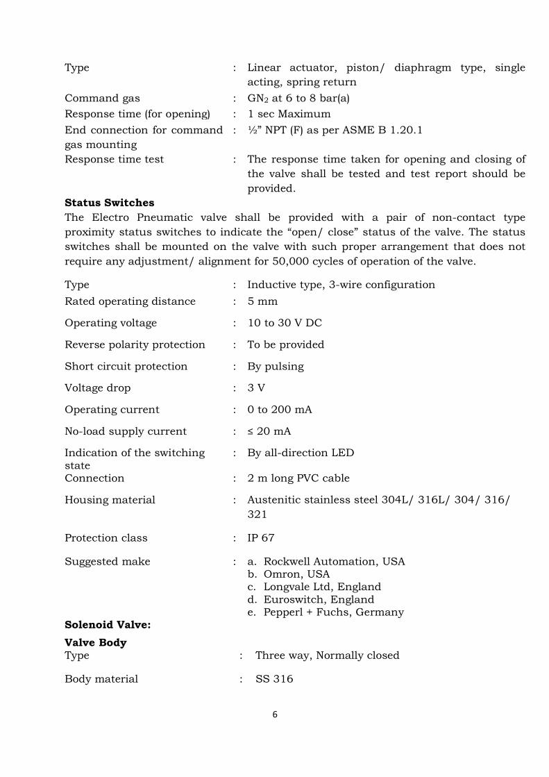
Actuator
6
Type : Linear actuator, piston/ diaphragm type, single
acting, spring return
Command gas : GN2 at 6 to 8 bar(a)
Response time (for opening) : 1 sec Maximum
End connection for command
gas mounting
: ½” NPT (F) as per ASME B 1.20.1
Response time test
:
The response time taken for opening and closing of
the valve shall be tested and test report should be
provided.
Status Switches
The Electro Pneumatic valve shall be provided with a pair of non-contact type
proximity status switches to indicate the “open/ close” status of the valve. The status
switches shall be mounted on the valve with such proper arrangement that does not
require any adjustment/ alignment for 50,000 cycles of operation of the valve.
Type : Inductive type, 3-wire configuration
Rated operating distance : 5 mm
Operating voltage : 10 to 30 V DC
Reverse polarity protection : To be provided
Short circuit protection : By pulsing
Voltage drop : 3 V
Operating current : 0 to 200 mA
No-load supply current : ≤ 20 mA
Indication of the switching state
: By all-direction LED
Connection : 2 m long PVC cable
Housing material : Austenitic stainless steel 304L/ 316L/ 304/ 316/
321
Protection class : IP 67
Suggested make : a. Rockwell Automation, USA b. Omron, USA c. Longvale Ltd, England d. Euroswitch, England e. Pepperl + Fuchs, Germany
Solenoid Valve:
Valve Body Type : Three way, Normally closed
Body material : SS 316

7
Housing : Die cast Aluminium epoxy painted
Stem : SS 316/ SS304
Seat : Viton
End connection : Threaded, 1/2" NPT (F) conforming to ANSI-B1.20.1.
Solenoid Power supply : 24 Vdc / 300 mA (max)
Solenoid coil : Suitable for continuous energization
Enclosure : IP 65
Coil insulation : Class F as defined in IS: 1271.
Coil pull in voltage : Between 50 to 70% of normal supply voltage
Coil drop out voltage : Between 30% to 50% of nominal supply voltage
Coil temperature rise : Not to exceed 70°C
Single or double coil : Double Coil
Response Time : Less than 100 msec.
Conduit connection : Enclosure shall have 1/2” NPT (F) connection for power Supply cable.
Mode of operation : Direct operated
Manual operation : Provision to open the valve using Lever
Freewheeling Diode : Two diode in series to be provided
Solenoid valve shall be mounted on the EP valve. Command gas tubing from GN2 line to the solenoid valve and to the actuator of EP valve are to be provided. Process condition Fluid : GN2
Pressure rating : 12 bar
Service Life : 50,000 cycles
Operating Temperature : 300K to 318K
Relative humidity : up to 95%
Supply of 2 core cable of minimum 50 meter length for command and 4 core cable of minimum 50 meter length for status of EP valve is in the scope of supplier.
3.13 Non-return valve:
Fluid medium : Given in table - 2
Working temperature range : 300 to 318K
Nominal size : Given in table - 2

8
Max Allowable Working Pressure (MAWP) : Given in table - 2
Cracking Pressure (Differential pressure
required to open the valve along intended
flow direction)
: 0. 5 bar
Quantity : Given in table - 2
End connection : Butt Weld with pipe stub, size
and schedule given in table - 2
Leak tightness across body : Bubble-tight as per API 598.
Leak tightness across seat along non-flow
(reverse) direction
: Bubble-tight as per API 598
Lift mechanism : Lift plug type, globe pattern
Cover : Screwed or bolted to body with
suitable seals
Plug : Renewable (replaceable) from
stem with insert
Test : Cracking pressure test for
opening of non-return valve at
0.5 bar pressure in flow direction.
Suggested make : a. Ampo Valves India Pvt Ltd,
Coimbatore
b. Flowserve India Controls Pvt Ltd,
Bangalore
c. Forbes Marshall Co, Pune
d. Instrumentation Ltd, Palakkad
e. MIL Controls Ltd, Thrissur
Table - 2
Specification For lubrication oil For pressurization circuit
Tag No. FVN 802 & 803 FVN 801
Fluid medium ISO VG 46 lubrication oil Gaseous Nitrogen
Nominal Size DN 50, 10S DN 32, 40S
Design Pressure 12 bar (a) 12 bar (a)
Quantity 2 Nos. 1 No.
Flow rate 5 lit/sec 75 gm/sec
End connection Butt welded, DN50, 10S Butt welded, DN 32, 40S
Material of construction
Body, cover : ASTM A 182 F 304/ 316 or
ASTM A351CF8/8M
Stem, plug : ASTM A 479 304/ 316
Pipe stub : ASTM A 312 TP 304/ 316

9
Plug insert / trim : PTFE / Glass filled PTFE/PEEK
Bolts : ASTM A 193 B 8
Nuts : ASTM A 194 Gr 8
3.14 Level indicator:
Level indicators for displaying oil level in supply tank & collection tank shall be
provided.
Quantity : 2 Nos.
Type : Piezometeric type
Working pressure : 11 bar (g) for supply tank & ambient pressure for collection tank
Fluid Medium : ISO VG 46 lubrication oil
Piezometric tube : Transparent
Material : suitable to withstand the working pressure
3.15 Differential Pressure Transmitter:
Differential pressure transmitter for displaying differential pressure at bottom
& top of supply tank shall be provided.
Type : Differential Pressure Transmitter
Measurement range : 0-0.5 bar (g)
Tag No. : FDP 801
Operating pressure : 12 bar (g)
Fluid Medium : ISO VG 46 lubrication oil
Quantity : 1 No.
Output : Two wire 4–20 mA with superimposed Digital communication HART protocol
Power Supply : 12 to 30 V DC
Local Indicator : 4 ½ digit LCD- Local Alpha Numeric Digital display in Engineering unit.
Accuracy : 0.5% of full scale reading
Over pressure limit : 1.25 times of Upper range Limit
Nominal operating temperature
: 300 – 318K
Suggested make : a. Emerson Process Management (India) Pvt. Ltd., Chennai
b. M/s. Honeywell sensing and control, Chennai
10
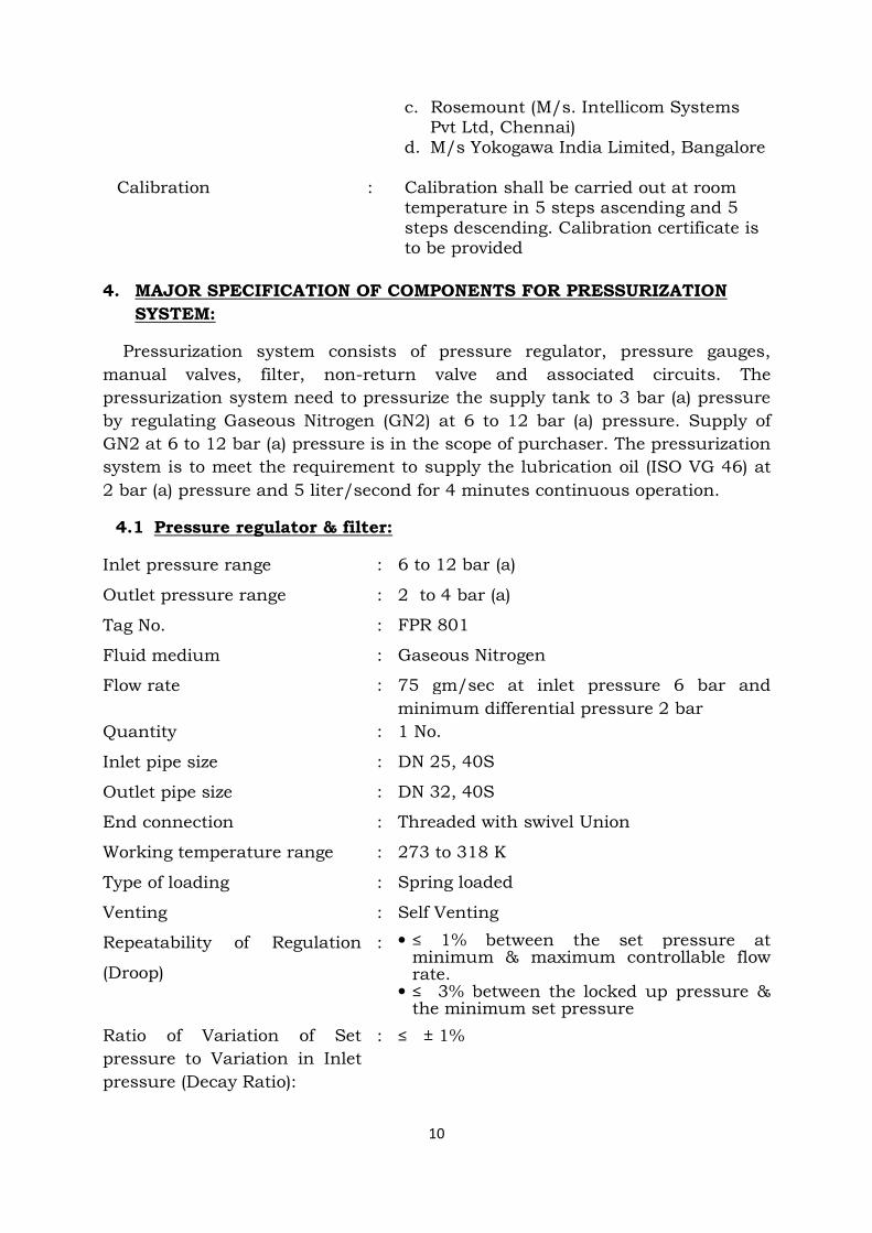
c. Rosemount (M/s. Intellicom Systems Pvt Ltd, Chennai)
d. M/s Yokogawa India Limited, Bangalore
Calibration : Calibration shall be carried out at room temperature in 5 steps ascending and 5 steps descending. Calibration certificate is to be provided
4. MAJOR SPECIFICATION OF COMPONENTS FOR PRESSURIZATION
SYSTEM:
Pressurization system consists of pressure regulator, pressure gauges,
manual valves, filter, non-return valve and associated circuits. The
pressurization system need to pressurize the supply tank to 3 bar (a) pressure
by regulating Gaseous Nitrogen (GN2) at 6 to 12 bar (a) pressure. Supply of
GN2 at 6 to 12 bar (a) pressure is in the scope of purchaser. The pressurization
system is to meet the requirement to supply the lubrication oil (ISO VG 46) at
2 bar (a) pressure and 5 liter/second for 4 minutes continuous operation.
4.1 Pressure regulator & filter:
Inlet pressure range : 6 to 12 bar (a)
Outlet pressure range : 2 to 4 bar (a)
Tag No. : FPR 801
Fluid medium : Gaseous Nitrogen
Flow rate : 75 gm/sec at inlet pressure 6 bar and
minimum differential pressure 2 bar
Quantity : 1 No.
Inlet pipe size : DN 25, 40S
Outlet pipe size : DN 32, 40S
End connection : Threaded with swivel Union
Working temperature range : 273 to 318 K
Type of loading : Spring loaded
Venting : Self Venting
Repeatability of Regulation
(Droop)
: • ≤ 1% between the set pressure at minimum & maximum controllable flow rate.
• ≤ 3% between the locked up pressure & the minimum set pressure
Ratio of Variation of Set
pressure to Variation in Inlet
pressure (Decay Ratio):
: ≤ ± 1%

11
Leak rate across the seat
(through) in closed condition
: Bubble tight
Leak rate across the body
(External)
: Bubble tight
Suggested make : a. Tescom Europe GmbH & Co KG, Germany
b. IMF sas, France c. Thompson Valves Ltd, England d. Parker Hannifin India Pvt Ltd, Banglore e. Swagelok, Chennai
Materials of Construction
Body, Plug : ASTM A 182 Gr. F 304/ 316
Plug insert / seat : PCTFE (Kel-F)
Seals, O- rings : Viton/ Buna N
Cleaning : All the interior flow surfaces of the pressure
regulator shall be degreased.
4.2 Safety Relief Valve:
Type : Conventional type
Fluid medium : Gaseous Nitrogen
Tag No. : FVR 801, FVR 802
Quantity : 2 Nos.
Set pressure : 11 bar (g)
Valve inlet flange size & rating : DN25, 150#, 40S, SRF
Valve outlet flange size & rating : DN50, 150#, 10S, SRF
Flow capacity : 1.2 x Regulator failure flow rate.
Orifice designation : E
Effective orifice area : 0.196 square inch
Working temperature range : 300 to 318 K
Over-pressure : 7 ± 3 % of set pressure
Blow-down : 5 % of set pressure
Permissible leakage rate across
seat
: As per API 527
End connection : Serrated Raised Face (SRF) flange
Design code : API 526/ ASME Section VIII, Division 1
Cleanliness : All the interior flow surfaces of the
valve shall be degreased and cleaned.
Suggested make : a. Fainger Leser Valves Pvt Ltd, Mumbai
b. Forbes Marshall Co, Pune
c. Instrumentation Ltd, Palakkad
d. Tyco Sanmar Ltd, Chennai
Material of Construction:
Body, bonnet : ASTM A 351 Gr. CF8/8M

12
Nozzle, seat : ASTM A 479 304/ 316/ 321
Spring : Stainless steel 316
Bolts : ASTM A 320 B 8
Nuts : ASTM A 194 8
4.3 Rupture Disk:
Type : Scored metal, pre-torqued, rupture disc
device along with safety head, studs and
nuts.
Fluid medium : Gaseous Nitrogen
Tag No. : FBD 801
Working temperature range : 273 to 318 K
Rupture pressure : 12 bar (g)
Disc size : DN25
Quantity : 1 No.
Flow capacity : 1.2 x Regulator failure flow rate.
Ratio of Operating Pressure to
burst Pressure
: 90 %
Orifice diameter : 12mm
Manufacturing tolerance : 0 %
Burst pressure tolerance : ± 5 %
Suggested make : a. BS&B Safety Syetems (India) Ltd, Chennai
b. Fike India pvt. Ltd., Pune
c. Rembe, Germany
d. Zook Enterprises, USA
Material of construction:
Disc : SS 304/316
Safety head : ASTM A 182 Gr. F 304/ 316
Studs : ASTM A 320 B 8
Nuts : ASTM A 194 8
4.4 Pressure gauges:
Type : Bourdon type gauge
Service fluid : Gaseous Nitrogen
Tag No. : FPL 801, 802, 803 & 804
Range : 0 to 20 bar
Dial size : 100mm
Quantity : 4 Nos.
Accuracy : ± 1% of Full Scale
Sensing element
material
: AISI 316

13
Movement material : AISI 316
End connection : ½” NPT (M)
Mounting : Direct mounting with bottom connection
Working temperature : 300 to 318 K
Over range protection : 130 % of full scale
Window : Shatter proof
Standard : IS:3624 / EN 837-1
Suggested make : a. Wika Instruments India Pvt Ltd, Chennai
b. Budenberg Gauge Pvt Ltd, Chennai
c. Baumer Technologies India Pvt Ltd, Chennai
d. Swagelok Chennai
e. ASHCROFT India Pvt. Ltd, Gandhinagar
Calibration test: Calibration shall be carried out for all the pressure gauges
and certificate shall be provided.
Each pressure gauges shall be mounted on 3-port, 2-way manifold valve.
4.5 Pressure Transmitter:
Type : Absolute Pressure Transmitter
Measurement Range : 0 to 18 bar
Tag No : FPI 801 Quantity : 1 No.
Service Medium : GN2
Maximum Turndown Ratio
(TD)
: 10:1
Output : Two wire 4–20 mA with superimposed
Digital communication HART protocol.
Power Supply : 12 to 30 V DC.
Local Indication : 4½ digits LCD – Local Alpha Numeric
Digital display in Engineering units.
Accuracy : 0.5% of full scale reading
Over Pressure limit : 1.25 times of Upper range Limit
Nominal operating
temperature
: 300 – 318K
Transmitter Process
connection
: ½ " – NPT (F)
Suggested make : a. Emerson Process Management (India)
Pvt. Ltd., Chennai
b. M/s. Honeywell sensing and control,
Chennai
c. Rosemount (M/s. Intellicom Systems

14
Pvt Ltd, Chennai)
d. M/s Yokogawa India Limited, Bangalore
Calibration : Calibration shall be carried out at room
temperature in 5 steps ascending and 5
steps descending. Calibration certificate is
to be provided
5. SPARE ITEMS:
Following spare items shall also be supplied
Sl. No
Description Size Material Quantity
1. Manual Valve (FVM 803S & 805S)
DN15, 150# Stainless steel 304 2 Nos.
2. Manual Valve (FVM 815S)
DN25, 150# Stainless steel 304 1 No.
3. Manual Valve (FVM 804S)
DN32, 150# Stainless steel 304 1 No.
4. Manual Valve FVM (808S)
DN50, 150# Stainless steel 304 1 No.
5. Manifold Valve (FVM 801S)
½” NPT, (3 port, 2 way)
Stainless steel 304 1 No.
6. Manifold Valve (FVM 817S)
½” NPT (5 port, 3 way)
Stainless steel 304 1 No.
7. Non return valve (FVN 801S)
DN32 Stainless steel 304 1 No.
8. Non return valve (FVN 802S)
DN50 Stainless steel 304 1 No.
9. Pressure gauge (FPL 810S & 802S)
0 to 20 bar - 2 Nos.
10. Stainless Steel Pipe DN15, 40S ASTM A312 TP 304 5m
11. Stainless Steel Pipe DN25, 40S ASTM A312 TP 304 5m
12. Stainless Steel Pipe DN32, 40S ASTM A312 TP 304 5m
13. Stainless Steel Pipe DN50, 10S ASTM A312 TP 304 5m
14. 90 o Elbow DN15, 40S ASTM A403 WP 304 2 Nos.
15. 90 o Elbow DN25, 40S ASTM A403 WP 304 1 No.
16. 90o Elbow DN32, 40S ASTM A403 WP 304 1 No.
17. 90 o Elbow DN50, 10S ASTM A403 WP 304 2 Nos.
18. Equal tee DN50, 10S ASTM A403 WP 304 1 No.
19. Flange DN15, 150#, 40S, SRF ASTM A182 F304 4 Nos.
20. Flange DN25, 150#, 40S, SRF ASTM A182 F304 4 Nos.
21. Flange DN32, 150#, 40S, SRF ASTM A182 F304 3 Nos.
22. Flange DN50, 150#, 10S, SRF ASTM A182 F304 6 Nos.
23. Concentric Reducer DN 32 X DN 25, 40S ASTM A403 WP 304 1 No.
24. Un-equal Tee DN25 X DN25 X DN15, 40S
ASTM A403 WP 304 1 No.

15
25. Un-equal Tee DN32 X DN32 X DN15, 40S
ASTM A403 WP 304 1 No.
26. Un-equal Tee DN32 X DN32 X DN25, 40S
ASTM A403 WP 304 1 No.
27. Rupture Disk (FBD 801S & 801SS)
DN25 -
2 Nos.
28. Spare filter element & seals for pressurization circuit filter
DN25, 25 micron
- 1 Set
29. Spare filter element & seals for oil feed circuit filter
DN50, 25 micron - 1 Set
30. Spare for pressure regulator along with spare filter elements
- - 1 Set
6. FABRICATION & ERECTION:
Fabrication of pipelines shall be carried out as per the drawings enclosed
herewith; minor changes if any in the routing also shall be carried out. All
machineries, tools, accessories & manpower required for fabrication & erection
is in the scope of supplier. Welding shall be as per ASME sec IX using TIG
process with argon as shielding gas. Prefabrication may be done at supplier’s
site. The prefabricated items along with support structural materials may be
brought to IPRC for final integration. Pressure gauges & pressure transmitter
shall be mounted with 3-port, 2-way manifold valve and differential pressure
transmitter shall be mounted with 5-port, 3-way manifold valve. The works at
IPRC involves tanks erection, piping fabrication and erection with necessary
testing like DP test & radiography. The installation and testing shall be done at
IPRC. The scope of final inspection covers hydro test for integrated circuits,
functional test for flow components and performance test at operating
parameters for the total system. Power supply for fabrication & erection shall
be provided by the purchaser to the supplier at free of cost. Welders, fitters &
helpers required for fabrication & erection shall be arranged by the Supplier.
6.1 Dye Penetrant Test:
All the socket weld joints shall be subjected to Dye Penetrant Test (DPT) at the
root and final passes. All the butt weld joints shall be subjected to DPT at the
root pass.

16
6.2 Radio-graphic test:
All the butt weld joints on the supply tank, collection tank & pipelines shall be
subjected to radio-graphic test with X-rays to 2-2T sensitivity. All the
radiographic films shall be submitted to purchaser for review.
6.3 Hydrostatic Pressure test:
The supply tank shall be subjected to hydrostatic pressure test with water at
1.3 times the Maximum Allowable Working Pressure (MAWP) as per ASME Sec
VIII Div. 1 at manufacturer’s works (MAWP of supply tank 11 bar(g)) &
pipelines shall be subjected to hydrostatic pressure test with water at 1.5 times
the Maximum Allowable Working Pressure (MAWP) as per ASME B 31.3 (MAWP
of pipeline 11 bar(g)) after fabrication and installation at IPRC.
6.4 Cleanliness:
The pressure fed lubrication system shall be properly cleaned. Pickling &
passivation shall be carried out for all the stainless steel pipelines before
welding with components
6.5 Painting
The supply tank, collection tank & structural supports of pressure fed
lubrication system shall be painted with two coats of smoke grey color paint
after application of two coats of suitable primer.
7. PRE-DELIVERY INSPECTION (PDI)
The Purchaser will carry out Pre-Delivery Inspection (PDI) of tanks, pipes,
fittings, components, instruments & pre-fabricated items at their discretion
at the Supplier’s works. The scope of inspection includes visual &
dimensional inspection, witness of hydrostatic pressure test and review of
certificate in support of material test, leak test etc as per the specification
document. However, acceptance of the lube oil system will be based on final
inspection after installation & commissioning at IPRC, Mahendragiri. It shall
be the responsibility of the supplier to intimate the Purchaser two weeks in
advance for PDI.
8. INSTALLATION
Installation of total pressure fed lubrication oil system which includes
installation of supply tank, collection tank, pipelines, filters, EP valve along
with supports at IPRC, Mahendragiri is in the scope of supplier. Supply of
stainless steel spiral wound PTFE with inner and outer ring gaskets, stainless
steel fasteners, stainless steel washers, foundation bolts, structural materials
for support fabrication is also in the scope of supplier. Minor civil works
(RCC/PCC) required for installation of above mentioned equipments and
pipelines including excavation of existing PCC floor shall be carried out by

17
supplier. All machineries, tools, accessories & manpower required for
installation of total pressure fed lubrication oil system is in the scope of
supplier.
9. COMMISSIONING:
It is the responsibility of supplier to install and commission the pressure fed
lubrication oil system at purchaser’s site and demonstrate its performance &
operation. All machineries, tools, accessories & manpower required for
commissioning of total pressure fed lubrication oil system is in the scope of
supplier. Gaseous nitrogen, lube oil & water for commissioning will be
provided by purchaser. The pressure fed lubrication oil system shall be
inspected for its performance after installation & commissioning at IPRC,
Mahendragiri.
10. CLEANING OF SITE:
After fabrication, erection and commissioning of pressure fed lube oil system at purchaser’s site the supplier shall clean the site.

18
SPECIAL CONDITIONS
1) Guarantee/Warrantee: The pressure fed lubrication oil system shall be
guaranteed / warranted for material, workmanship & satisfactory
performance over a period of 12 months from the date of commissioning at
purchaser’s site.
2) Documentation: The following documents (in English) shall be provided by
the supplier at the different stages specified thereupon:
i) Along with Quotation:
• A complete technical description along with drawings &
catalogues of the products featuring the different components
and accessories.
• Deviations, if any, from the tender enquiry specification shall be
explicitly spelt out otherwise it will be presumed that the offer
meets the tender specification.
• The company profile of the supplier highlighting the following:
a) Status as to whether the supplier is a manufacturer, trader,
dealer, stockist, agent, etc.
b) Clientele specifying the clients to whom the supplier has
supplied similar products indicating their address, telephone
number, fax, e-mail, contact person, etc
c) Copies of earlier purchase order as evidence for supply of
similar system shall be submitted along with quotation.
• Price format: Price shall be quoted as per the attached price
format Annexure -2.
• If any of the detail required as per tender is not provided, the
offer will be summarily rejected.
ii) Within 15 days after placement of Purchase Order:
• Detailed fabrication drawings of piping are to be prepared by the
supplier and submitted to purchaser for approval within 15 days
after placement of purchase order.

19
• Supplier shall provide design calculations and fabrication
drawings of supply tank & collection tank along with its
supports to the purchaser within 15 days after placement of
purchase order. Only after approval by purchaser the supplier
shall proceed with realization of tanks and supports. Purchaser’s
approval will not absolve the supplier’s responsibility to comply
with purchase order specification.
iii) Along with consignment:
a) A complete technical description, instruction manual along
with drawings & catalogues of the products featuring the
different components and accessories along with operating
instructions.
b) Manuals for operation, maintenance and trouble-shooting.
iv) On commissioning
a) Guarantee certificate.
3) Completion Period:
The total work period, reckoned from the date of award of Purchase Order to the
date of commissioning and final acceptance of the system shall be 6 months as
per the following breakup.
Design calculation, fabrication drawings review & clearance : 1 month
Supply of materials : 4 months
Fabrication, erection & commissioning : 1 month
4) No facilities for transport, canteen and lodging will be provided by IPRC during fabrication, erection & commissioning.
5) Payment Terms:
100% within 30 days after Installation, Commissioning and acceptance of
Lube Oil System at purchaser’s site.

Annexure - 2
20
Price format for augmentation of existing pump operated lubrication oil system (LOS) to fail safe pressure fed lubrication oil system:
Sl. No
Description of Item Size /
Specification Quantity Unit Rate
(Rs.) Total (Rs.)
1. Supply Tank 1m(Ø)x1.5m(l) 1 No.
2. Collection Tank 1.5m(l)x0.9m(w) x 1.3m(h)
1 No.
3. Manifold Valve (3 port, 2 way) ½” NPT 6 Nos.
4. Manifold Valve (5 port, 3 way) ½” NPT 2 Nos.
5. Manual Valve DN15, 150# 7 Nos.
6. Manual Valve DN32, 150# 2 Nos.
7. Manual Valve DN25, 150# 4 Nos.
8. Manual Valve DN50, 150# 5 Nos.
9. Stainless Steel Pipe DN15, 40S 15m
10. Stainless Steel Pipe DN32, 40S 20m
11. Stainless Steel Pipe DN25, 40S 15m
12. Stainless Steel Pipe DN50, 10S 40m
13. 90o Elbow DN15, 40S 10 Nos.
14. 90o Elbow DN32, 40S 4 Nos.
15. 90o Elbow DN25, 40S 3 Nos. 16. 90o Elbow DN50, 10S 11 Nos.
17. Equal tee DN50, 10S 5 Nos.
18. Flange DN15, 150#, SRF 18 Nos. 19. Flange DN32, 150#, SRF 14 Nos.
20. Flange DN25, 150#, SRF 19 Nos.
21. Flange DN50, 150#, SRF 32 Nos.
22.Concentric Reducer DN 32 X DN 25,
40S 2 Nos.
23.Un-equal Tee DN25 X DN25 X
DN15, 40S 2 Nos.
24.Un-equal Tee DN32 X DN32 X
DN15, 40S 3 Nos.
25.Un-equal Tee DN32 X DN32 X
DN25, 40S 2 Nos.
26. Pressure regulator with filter DN25, 25µ 1 No.
27. Safety Relief Valve DN25, 150# 2 Nos.
28. Rupture Disk DN25, 150# 3 Nos.
29. Filter DN50, 150#, 25µ 1 No.
30. EP Valve DN50, 150# 1 No.
31. Pressure gauge with manifold valve 0 to 20 bar 6 Nos.
32. Oil Level Indicator - 2 Nos.
33. Non return valve DN50 3 Nos.
34. Non return valve DN32 2 Nos.
35. Filter DN25, 150#, 25µ 1 No.
36.Pressure transmitter with manifold valve - 1 No.
37.Differential pressure transmitter with manifold valve
- 1 No.

Annexure - 2
21
38.Spare filter element & seals for oil feed circuit filter
DN50, 25µ 1 Set
39.Spare filter element & seals for pressurization circuit filter
DN25, 25µ 1 Set
40.Spare for pressure regulator along with spare filter elements - 1 Set
41. Fabrication & erection - 1 Lot
42. Installation & Commissioning - 1 Lot Sub-total
Taxes
Packing & Forwarding
Freight
Grand Total
Note: Spare items are also included


TITLE: Piping Layout of Pressure Fed Lubrication System
R0Drawing No.: SCFT/LOS/LAYOUT/02/2018 REV.Sheet 01 of 01
NOTE:-
SUPPLYTANK
Page - 24