
Technical Specification of Hydraulic Dampers for ...
24
REVISION OF SPECIFICATION / STR Item Name: TECHNICAL SPECIFICATION OF HYDRAULIC DAMPERS FOR CONVENTIONAL LOCOMOTIVES EXCEPT WDM3D (EQUALISER LESS BOGIE) LOCOMOTIVE. Specification No: MP.0.49.00.16 1. RDSO is reviewing the specification/STR to cater to the latest technological developments in the field, modify clauses not relevant in the present context and making them more enabling with focus on functional requirements. 2. It is requested that your comments / suggestions with regard to improvements /modifications in specification / STR of the abovementioned item may be submitted in the following format along with the justification for the changes required. Part A: Basic Information SN Particulars Information 1. Name 2. Designation 3. Professional Qualification 4. Organization / Firm‟s Name 5. Address for Correspondence 6. Contact No. 7. Email ID 8. Whether firm is registered with RDSO for the subject item. If yes, details like date of registration, current status etc. If no, firm‟s experience in manufacturing of subject item or similar item 8. Whether any technical document/Report/Study to support suggested changes is available / enclosed for better appreciation Part B: Comments / suggestions on the specification SN Clause No. of RDSO STR/ Spec Clause, as it exists in RDSO STR/ Spec Clause , as it should read after incorporation of comments /suggestions in the RDSO Spec / STR Justification for changes Comments may be sent to following address within one month from the date of publication on rdso.indianrailways.gov.in Dy. Director/MP(VDG) Research Designs and Standards Organization, Manak Nagar, Lucknow – 226011 Email: [email protected]
Transcript of Technical Specification of Hydraulic Dampers for ...

REVISION OF SPECIFICATION / STR
Item Name: TECHNICAL SPECIFICATION OF HYDRAULIC DAMPERS FOR CONVENTIONAL LOCOMOTIVES EXCEPT WDM3D (EQUALISER LESS BOGIE) LOCOMOTIVE.
Specification No: MP.0.49.00.16
1. RDSO is reviewing the specification/STR to cater to the latest technological developments in the field, modify clauses not
relevant in the present context and making them more enabling with focus on functional requirements.
2. It is requested that your comments / suggestions with regard to improvements /modifications in specification / STR of the abovementioned item may be submitted in the following format along with the justification for the changes required.
Part A: Basic Information
SN Particulars Information
1. Name
2. Designation
3. Professional Qualification
4. Organization / Firm‟s Name
5. Address for Correspondence
6. Contact No.
7. Email ID
8. Whether firm is registered with RDSO for the subject item. If yes, details like date of registration, current status etc. If no, firm‟s experience in manufacturing of subject item or similar item
8. Whether any technical document/Report/Study to support suggested changes is available / enclosed for better appreciation
Part B: Comments / suggestions on the specification
SN Clause No. of RDSO STR/ Spec
Clause, as it exists in RDSO STR/ Spec
Clause , as it should read after incorporation of comments /suggestions in the RDSO Spec / STR
Justification for changes
Comments may be sent to following address within one month from the date of publication on rdso.indianrailways.gov.in Dy. Director/MP(VDG) Research Designs and Standards Organization, Manak Nagar, Lucknow – 226011
Email: [email protected]

Technical Specification of Hydraulic Dampers for Conventional Locomotives except WDM3DLocomotive (With equalizer less bogie)
Hkkjr ljdkj] jsy eU=zky;
GOVERNMENT OF INDIA
MINISTRY OF RAILWAYS
TECHNICAL SPECIFICATION OF
HYDRAULIC DAMPERS FOR CONVENTIONAL LOCOMOTIVES
EXCEPT WDM3D (EQUALISER LESS BOGIE) LOCOMOTIVE
No. MP.0.49.00.16 (Revision - 03)
July’ 2020
vuqla/kku vfHkdYi vkSj ekud laxBu
y[kuÅ&226 011
RESEARCH DESIGNS & STANDARDS ORGANISATION
LUCKNOW - 226 011
R.D.S.O
Technical Specification of Hydraulic Dampers for Conventional Locomotives except WDM3DLocomotive (With equalizer less bogie)
CONTENTS
Sr. Description Page
1. Scope 1
2. Deviation(s) 1
3. Minimum General Requirements of the Firm 1
4. Technical Requirements
1-3
5. Endurance Testing of Hydraulic Dampers 3
6. Guarantee/ Warranty 4
7. Sampling 4
8. Deliverables 4
9. Marking 4
10. Packing 4
11. Overhauling Interval 4
12. Field Trials 4
13. Storage 4
14. Vendor Changes in Approved Status 4
15. Inspection 4
16. Preference to make in India 4
Annexure-I Testing procedure of Cardanic, Twisting and Bushing Radial Stiffness of
Hydraulic Dampers for Alco locomotives
i
Annexure-II Endurance Testing Procedure For Hydraulic Dampers Alco Locomotives ii
Annexure-III Quality Assurance & Guarantee Certificate
v
Annexure-IV Proforma for Reporting Damper Failures of Locomotives vi

Motive Power Directorate (VDG), RDSO, Lucknow Specification No. MP.0.49.00.16 (Rev.03) July.’ 2020 Page 1 of 10
TECHNICAL SPECIFICATION OF HYDRAULIC DAMPERS FOR CONVENTIONAL LOCOMOTIVES EXCEPT WDM3D
(EQUALISER LESS BOGIE) LOCOMOTIVE
1. SCOPE This document covers the technical specifications for vertical & lateral hydraulic dampers for Conventional locomotives except WDM3D locomotive (With equalizer less bogies).
2. DEVIATION(s)
If deviations from original design, dimensions etc. are desired by tenderer, specific proposals with reasons shall be submitted to the purchaser. Commencement of manufacture shall not be done till the purchaser grants clear authorization for acceptance of the deviation(s).
3. MINIMUM GENERAL REQUIREMENTS OF THE FIRM
The firm shall be met minimum testing & manufacturing infrastructure to RDSO STR No. MP.STR.VL-01.01.16
(Revision-01 or Latest).
4. TECHNICAL REQUIREMENTS
4.1 Dimensions & Damping Capacities
The Hydraulic Damper shall conform to the latest version of the concerned RDSO Drawing including dimensions, damping capacities at room temperature condition. The damper shall be easy to overhaul and adjustable as per requirements.
4.2 Operating environmental conditions:
4.2.1 The damper shall be resistant to the following operating environmental conditions to which it may be exposed during service:
− Projection of ballast
− Exposure to oil or petroleum
− Exposure to organic waste
− Wind, rain, snow, coal dust, sand storms
− Sand, brake and ferric oxide dust (abrasion of wheels, brake blocks and tracks)
− Saline spray
− washing plant agent (both acids and alkalis)
− 100% humidity
4.2.2 The damper shall be required to function safely at operating temperature in the range from - 100C to 70 0C. After
operating in these extremes, the damper shall be required to fully recover its functionality. Furthermore, the damper
shall not display any fluid leaks or any sign of failure or cracking in the damper components.
Salt spray test (Saline spray) to be done as per ISO-9227/ASTM B-117 and remaining environmental
conditions shall be monitored in the field.
4.3 Surface protection
All the parts of the damper in contact with the ambient air shall be protected from corrosion. The
protection shall be ensured either by the nature of materials used or by suitable painting / surface
treatments.
Damper material shall be compatible with following paints:
Primer: High solid epoxy primers, High solid alkyd primers
Paint: Aliphatic polyurethane enamels or two part epoxy paint

Motive Power Directorate (VDG), RDSO, Lucknow Specification No. MP.0.49.00.16 (Rev.03) July.’ 2020 Page 2 of 10
4.4 Strength
The construction of Hydraulic Damper shall be such as to withstand the static compressive axial load of 3 tonnes (when fully closed) and a tensile load of 3 tonnes (when fully extended) without any failure, damage or permanent change in damping characteristic at nominal velocity and Stroke shall be ±9.5 mm or reduction in service interval. All welded joints of the Hydraulic Damper shall be free from welding defects and shall be sufficiently strong to withstand the loads intended.
4.5 Reliability
Reliability of the component shall meet the following locomotive reliability goals. Failure per locomotive year needing warranty replacement shall also not exceed 0.010. Failure per locomotive year causing line failure and unscheduled replacement shall not exceed 0.007. Failure means leakage of oil, deterioration in damper performance by 30% or more, breakage of any part of damper.
4.6 Force - Displacement Characteristic
The shape of the Force - Displacement curve or Hysteresis Cycle should be regular and symmetrical as shown here.
The hysteresis cycle should be free from:
− flex as shown in this figure with letter A, B & C
− Local vibrational phenomena
− Jumps and sudden change in the shape of the curve
4.7 Overall Damping Characteristics
The overall damping forces on the compression and extension strokes of the damper, taken separately, shall be as specified in the drawing(s).
The Hydraulic Damper shall be assembled in such a manner that the damping shall be uniform throughout the stroke i.e. the damping characteristics shall not have any sudden deviation or changes throughout the stroke.
The stipulated tolerances and requirements shall apply at all points within the required working stroke of the Hydraulic Damper.
4.8 Twisting and Cardanic angles and Radial stiffness of Spheri bloc:
The twisting and cardanic angles of damper shall be as per specified in the drawings. Bushing radial stiffness shall be more than 20 KN/mm.
The test is to be carried out as per procedure given in Annexure –I.
4.9 Damper Oil
The details of damper oil including type, viscosity and amount of the damper oil shall be provided by the supplier.
4.10 Performance characteristics & Maintainability
The dampers shall be of robust construction and shall be rebuildable type. It shall be possible to recondition and recalibrate it to “as new” conditions. It shall have degressive or blow off feature to limit the maximum forces created by severe track conditions, where piston speed may reach 0.30 m/sec. The force rate shall be linear only up to a certain limit. Maximum force even at higher speeds shall not be more than 25% of the force specified as given in relevant drawing at 0.10m/sec.
4.11 Dust Cover and Casing Tube
The joint shall be proven strong enough between piston eye and dust cover shall be done to prevent breakage at
the joint. Casing tubes shall be made of steel by accurate and precision

Motive Power Directorate (VDG), RDSO, Lucknow Specification No. MP.0.49.00.16 (Rev.03) July.’ 2020 Page 3 of 10
Welding process or of seamless tube and similarly protection cover also be sufficiently strong and similarly protection cover shall also be strong to increase the life of dampers.
4.12 Positive Locking of Piston and Piston Rod
Due to higher forces encountered at higher operating speeds, there is a possibility that piston can rotate and free itself from piston rod. Therefore, proper locking of piston with piston rod shall be ensured by appropriate method
4.13 Sealing Arrangement
The damper should protected against ingress of dust along with piston rod by using suitable sealing arrangement with better wiping properties , provision of additional dust lip etc.
4.14 Internal Design
It shall have all the constructional features to reduce friction, provide protection against dust and ensure long life. The internal mechanism shall have provision so that in any odd situation, the force of oil goes beyond a prescribed limit; the system shall take action automatically to prevent the failure of the damping system. The valve system shall be noise free and there shall also be arrangement to ensure absence of metal to metal contact in the piston & guide.
4.15 Surface finish of cylinder & piston rod:
A high degree of surface finish of the order of 0.1 to 0.3 µm Ra for piston rod shall be maintained during
manufacture.
4.16 Vibrational characteristic
The dampers shall be able to withstand the vibration levels of the intended application in primary / secondary suspension stages of locomotive bogie. Particularly yaw damper shall be specially designed to control small amplitude sinusoidal bogie rotational movements.
Damper shall function under exceptional accelerations for 5 hours as per IEC: 61373):
Locations Primary vertical Secondary Lateral/yaw
Vertical +/- 50 g +/- 6 g
Lateral +/- 5g +/- 3g
Longitudinal +/- 5g +/- 5g
Vibrational Test of Hydraulic Damper shall be done during the prototype inspection or when a new design is introduced or when there are any significant design alteration/quality issues.
4.17 Leakage
The damper shall operate without excessive loss of oil throughout its operating life. Oil loss shall be considered excessive when there is visible evidence of accumulation of oil in the form of drip on the body of the damper.
4.18 Salt spray test
Surface treatment must have durability against minimum 240 hours salt spray test as per ISO 9227/ASTM B-117. The result of test for degree of rusting shall be conforming to Ri 1 as per ISO 4628-3 and adhesion of paint shall be conforming to 0 until 1 (any squares may not come off) as per ISO 2409.
Salt spray test shall be carried out during the prototype inspection or when a new design is introduced or when there are any significant design alteration/quality issues.
5. ENDURANCE TESTING OF HYDRAULIC DAMPERS
Endurance Testing of Hydraulic Damper should be done during the initial approval of a supplier as RDSO approved source for supply of Hydraulic Dampers to Railways/ PUs, or when a new design is introduced or when there is any significant design alteration.
Motive Power Directorate (VDG), RDSO, Lucknow Specification No. MP.0.49.00.16 (Rev.03) July.’ 2020 Page 4 of 10
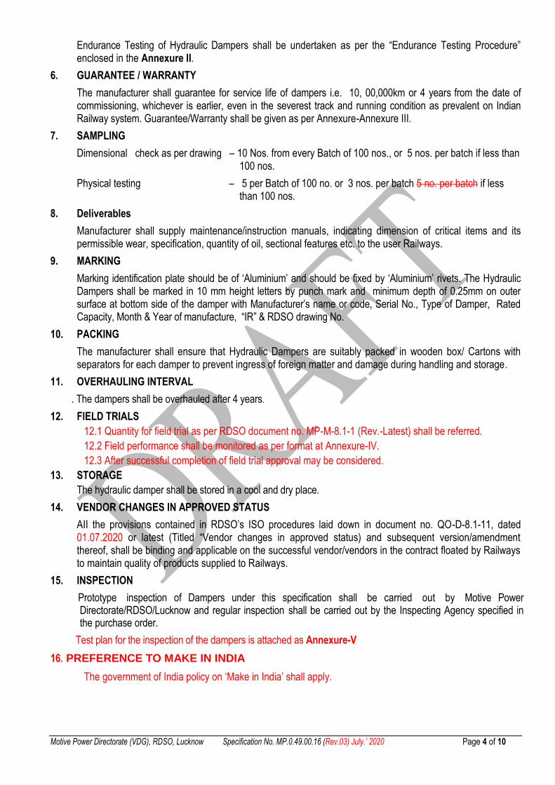
Endurance Testing of Hydraulic Dampers shall be undertaken as per the “Endurance Testing Procedure” enclosed in the Annexure II.
6. GUARANTEE / WARRANTY
The manufacturer shall guarantee for service life of dampers i.e. 10, 00,000km or 4 years from the date of commissioning, whichever is earlier, even in the severest track and running condition as prevalent on Indian Railway system. Guarantee/Warranty shall be given as per Annexure-Annexure III.
7. SAMPLING
Dimensional check as per drawing – 10 Nos. from every Batch of 100 nos., or 5 nos. per batch if less than 100 nos.
Physical testing – 5 per Batch of 100 no. or 3 nos. per batch 5 no. per batch if less than 100 nos.
8. Deliverables
Manufacturer shall supply maintenance/instruction manuals, indicating dimension of critical items and its permissible wear, specification, quantity of oil, sectional features etc. to the user Railways.
9. MARKING
Marking identification plate should be of „Aluminium‟ and should be fixed by „Aluminium‟ rivets. The Hydraulic Dampers shall be marked in 10 mm height letters by punch mark and minimum depth of 0.25mm on outer surface at bottom side of the damper with Manufacturer‟s name or code, Serial No., Type of Damper, Rated Capacity, Month & Year of manufacture, “IR” & RDSO drawing No.
10. PACKING
The manufacturer shall ensure that Hydraulic Dampers are suitably packed in wooden box/ Cartons with separators for each damper to prevent ingress of foreign matter and damage during handling and storage.
11. OVERHAULING INTERVAL
. The dampers shall be overhauled after 4 years.
12. FIELD TRIALS
12.1 Quantity for field trial as per RDSO document no. MP-M-8.1-1 (Rev.-Latest) shall be referred.
12.2 Field performance shall be monitored as per format at Annexure-IV.
12.3 After successful completion of field trial approval may be considered.
13. STORAGE
The hydraulic damper shall be stored in a cool and dry place.
14. VENDOR CHANGES IN APPROVED STATUS
AII the provisions contained in RDSO‟s ISO procedures laid down in document no. QO-D-8.1-11, dated 01.07.2020 or latest (Titled “Vendor changes in approved status) and subsequent version/amendment thereof, shall be binding and applicable on the successful vendor/vendors in the contract floated by Railways to maintain quality of products supplied to Railways.
15. INSPECTION
Prototype inspection of Dampers under this specification shall be carried out by Motive Power Directorate/RDSO/Lucknow and regular inspection shall be carried out by the Inspecting Agency specified in the purchase order.
Test plan for the inspection of the dampers is attached as Annexure-V
16. PREFERENCE TO MAKE IN INDIA
The government of India policy on „Make in India‟ shall apply.
Motive Power Directorate (VDG), RDSO, Lucknow Specification No. MP.0.49.00.16 (Rev.03) July.’ 2020 Page 5 of 10
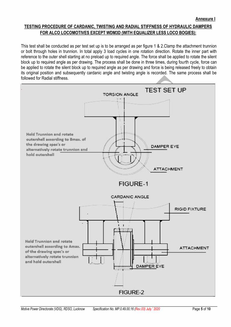
Annexure I
TESTING PROCEDURE OF CARDANIC, TWISTING AND RADIAL STIFFNESS OF HYDRAULIC DAMPERS
FOR ALCO LOCOMOTIVES EXCEPT WDM3D (WITH EQUALIZER LESS LOCO BOGIES):
This test shall be conducted as per test set up is to be arranged as per figure 1 & 2.Clamp the attachment trunnion or bolt through holes in trunnion. In total apply 3 load cycles in one rotation direction. Rotate the inner part with reference to the outer shell starting at no preload up to required angle. The force shall be applied to rotate the silent block up to required angle as per drawing. The process shall be done in three times, during fourth cycle, force can be applied to rotate the silent block up to required angle as per drawing and force is being released freely to obtain its original position and subsequently cardanic angle and twisting angle is recorded. The same process shall be followed for Radial stiffness.
.

Motive Power Directorate (VDG), RDSO, Lucknow Specification No. MP.0.49.00.16 (Rev.03) July.’ 2020 Page 6 of 10
Annexure II
ENDURANCE TESTING PROCEDURE FOR HYDRAULIC DAMPERS FOR HYDRAULIC DAMPERS FOR ALCO
LOCOMOTIVES EXCEPT WDM3D (WITH EQUALIZER LESS LOCO BOGIES)
After ascertaining the damping characteristics and strength test, the hydraulic damper samples to be tested shall be subjected to endurance testing as follows:
.1 Procedures
Two of the samples that have passed the tests under Para 4.1 to 4.18 shall be randomly selected for endurance testing.
The hydraulic dampers shall be tested in their normal plane of operation.
The hydraulic damper shall be connected to the testing machine with its flexible end mountings in the same manner as it is done on the locomotives. No additional flexible elements shall be used for this purpose.
The endurance testing machine shall enable keeping one end of the hydraulic damper fixed and the other end oscillating at 1.67 Hz with amplitude of ±9.5mm from mean position corresponding to a maximum velocity of 10 cm/sec. In addition, a side load shall be applied which shall be equivalent to 50% of torsion angle or conical angle, whichever is greater Hydraulic damper shall thus be subjected to a total 3 million cycles. The damper oil temperature should not exceed 70°C temperature during the endurance test.
After completion of 8 lakh, 16 lakh, 24 lakh and 30 lakh cycles each, the hydraulic damper shall be removed from endurance testing machine and re-tested for overall damping characteristics as mentioned above after it cools to room temperature so that the damping characteristics test is carried out with the hydraulic damper at a temperature between 27° C to 33° C inclusive. The necessary data should be recorded as per the Proforma enclosed at Annexure – I C. A continuous record of endurance testing shall be maintained in the log sheet as per the Proforma placed at Annexure – I D.
The cyclic working on endurance testing machine shall preferably be continuous except for short intervals when hydraulic damper is removed for checking their capacity or when circumstances are beyond the control of testing agency e.g. power failures etc.
However, Manufacturers may carry out the endurance testing at more severe conditions than specified above.
.2 Criteria for Acceptance
After completion of recommended endurance cycles as above, the sample hydraulic dampers shall be considered to have passed this endurance test if:
a. No damage or distortion to damper components or oil leakage occurs.
b. The damping characteristics do not deteriorate beyond ±20% of rated damping capacity upto 16 lakh cycles and ±25% beyond that.
........
Motive Power Directorate (VDG), RDSO, Lucknow Specification No. MP.0.49.00.16 (Rev.03) July.’ 2020 Page 7 of 10
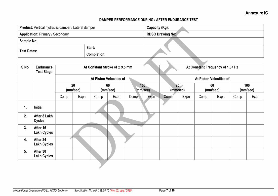
Annexure IC
DAMPER PERFORMANCE DURING / AFTER ENDURANCE TEST
Product: Vertical hydraulic damper / Lateral damper Capacity (Kg):
Application: Primary / Secondary RDSO Drawing No:
Sample No:
Test Dates: Start:
Completion:
S.No. Endurance Test Stage
At Constant Stroke of ± 9.5 mm At Constant Frequency of 1.67 Hz
At Piston Velocities of At Piston Velocities of
20 (mm/sec)
60 (mm/sec)
100 (mm/sec)
20 (mm/sec)
60 (mm/sec)
100 (mm/sec)
Comp Expn Comp Expn Comp Expn Comp Expn Comp Expn Comp Expn
1. Initial
2. After 8 Lakh Cycles
3. After 16 Lakh Cycles
4. After 24 Lakh Cycles
5. After 30 Lakh Cycles

Motive Power Directorate (VDG), RDSO, Lucknow Specification No. MP.0.49.00.16 (Rev.03) July.’ 2020 Page 8 of 10
Annexure ID LOG SHEET FOR ENDURANCE TESTING DATA OF HYDRAULIC DAMPERS
Product: Vertical hydraulic damper / Lateral damper Capacity (Kg):
Application: Primary / Secondary RDSO Drawing No:
Sample No:
Test Dates: Start:
Completion:
Stroke (mm): Frequency (Hz): Velocity (cm/sec):
Sl. No.
Date Started time
Stopped time
Total hours
No. of cycles
Cumulative no. of cycles
completed
Temperature of damper
(ºC)
Remarks
Motive Power Directorate (VDG), RDSO, Lucknow Specification No. MP.0.49.00.16 (Rev.03) July.’ 2020 Page 9 of 10
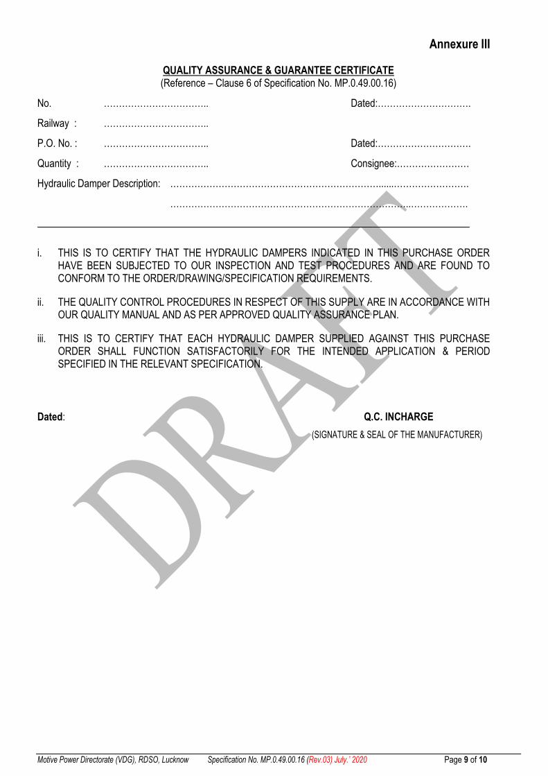
Annexure III
QUALITY ASSURANCE & GUARANTEE CERTIFICATE (Reference – Clause 6 of Specification No. MP.0.49.00.16)
No. …………………………….. Dated:………………………….
Railway : ……………………………..
P.O. No. : …………………………….. Dated:………………………….
Quantity : …………………………….. Consignee:……………………
Hydraulic Damper Description: ……………………………………………………………......…………………….
……………………………………………………………………..……………….
i. THIS IS TO CERTIFY THAT THE HYDRAULIC DAMPERS INDICATED IN THIS PURCHASE ORDER HAVE BEEN SUBJECTED TO OUR INSPECTION AND TEST PROCEDURES AND ARE FOUND TO CONFORM TO THE ORDER/DRAWING/SPECIFICATION REQUIREMENTS.
ii. THE QUALITY CONTROL PROCEDURES IN RESPECT OF THIS SUPPLY ARE IN ACCORDANCE WITH OUR QUALITY MANUAL AND AS PER APPROVED QUALITY ASSURANCE PLAN.
iii. THIS IS TO CERTIFY THAT EACH HYDRAULIC DAMPER SUPPLIED AGAINST THIS PURCHASE ORDER SHALL FUNCTION SATISFACTORILY FOR THE INTENDED APPLICATION & PERIOD SPECIFIED IN THE RELEVANT SPECIFICATION.
Dated: Q.C. INCHARGE
(SIGNATURE & SEAL OF THE MANUFACTURER)
Motive Power Directorate (VDG), RDSO, Lucknow Specification No. MP.0.49.00.16 (Rev.03) July’ 2020 10 of 10
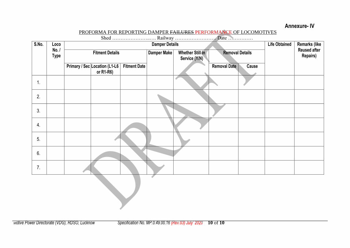
Annexure- IV PROFORMA FOR REPORTING DAMPER FAILURES PERFORMANCE OF LOCOMOTIVES
Shed …………………..…. Railway ……………………. Date ……………
S.No. Loco No. / Type
Damper Details Life Obtained Remarks (like Reused after
Repairs) Fitment Details Damper Make Whether Still in
Service (Y/N) Removal Details
Primary / Sec Location (L1-L6 or R1-R6)
Fitment Date Removal Date Cause
1.
2.
3.
4.
5.
6.
7.

Motive Power Directorate (VDG), RDSO, Lucknow Specification No. MP.0.49.00.16 (Rev.03) July’ 2020 10
of 10
Annexure- V
Test Plan for Hydraulic Dampers of Conventional Locomotives except WDM3D
(Equaliser Less Bogie) locomotive
1. SCOPE
This inspection plan covers the checks to be carried out by the Authorized Inspecting Agency during inspection of Hydraulic Dampers of Conventional locomotives except WDM3D (Equaliser less bogie) locomotive. The finished dimensions shall be subjected to inspection by the Authorized Inspecting Agency as detailed in this Inspection Plan to ascertain the quality of Hydraulic Dampers.
2. CONTRACT DOCUMENTS
Sl. Description
1. Purchase order in reference
2. Drawing(s) referred in purchase order
3. RDSO‟s specification No MP.0.49.00.16 (Revision -02 or Latest).
4. RDSO approved Quality Assurance Plan of the firm for Hydraulic Dampers
3. GENERAL CHECKS BY THE INSPECTOR
Before commencing the inspection, the Inspector shall ensure that:
i. Prototype inspection of Dampers under this inspection shall be carried out by Motive Power
Directorate/RDSO/Lucknow and regular inspection shall be carried out by the Inspecting Agency
specified in the purchase order.
ii. The delivery period of the Purchase Order is valid.
iii. Inspection call is well in advance before D.P. and address of works is same as given in the Vendor
directory.
iv. Valid copies of QAP and relevant drawings as per the P.O are available.
v. Check the internal inspection record carried out at various stages of manufacture of the product by the
firm‟s quality control department for the product being offered and confirms that the results of the
internal inspection records are in order.
vi. The measuring instruments, gauges, testing facilities, etc are in working order and they are properly
calibrated.
vii. The observations on general checks carried out by inspecting agency shall be recorded in Proforma A.
4. INSPECTION PROCEDURE
4.1 Sample Size
Samples for various tests shall be drawn from each lot of 100 nos. offered for inspection by the representative of Authorized Inspecting Agency. The following tests shall be carried out:
Sl. Test Sample Size
1. Visual Inspection 10 Nos.
2. Dimensional check 10 Nos.
Motive Power Directorate (VDG), RDSO, Lucknow Specification No. MP.0.49.00.16 (Rev.03) July’ 2020 10
of 10
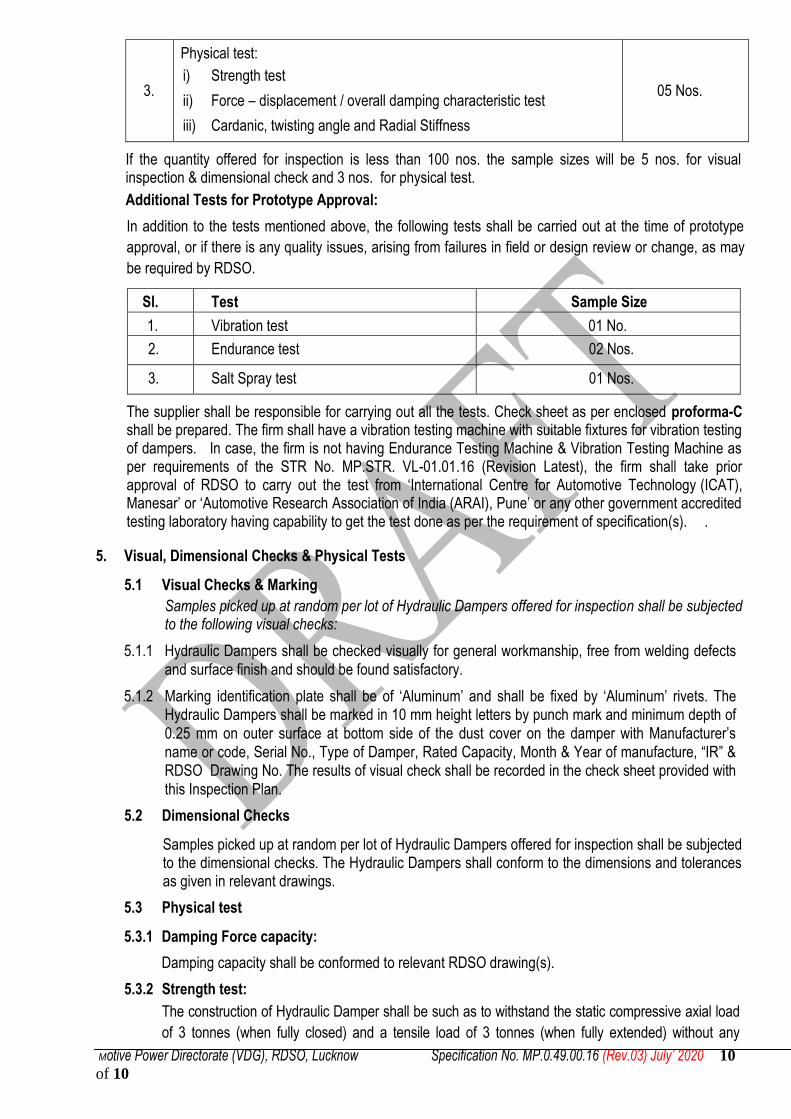
3.
Physical test:
i) Strength test
ii) Force – displacement / overall damping characteristic test
iii) Cardanic, twisting angle and Radial Stiffness
05 Nos.
If the quantity offered for inspection is less than 100 nos. the sample sizes will be 5 nos. for visual inspection & dimensional check and 3 nos. for physical test.
Additional Tests for Prototype Approval:
In addition to the tests mentioned above, the following tests shall be carried out at the time of prototype
approval, or if there is any quality issues, arising from failures in field or design review or change, as may
be required by RDSO.
Sl. Test Sample Size
1. Vibration test 01 No.
2. Endurance test 02 Nos.
3. Salt Spray test 01 Nos.
The supplier shall be responsible for carrying out all the tests. Check sheet as per enclosed proforma-C shall be prepared. The firm shall have a vibration testing machine with suitable fixtures for vibration testing of dampers. In case, the firm is not having Endurance Testing Machine & Vibration Testing Machine as per requirements of the STR No. MP.STR. VL-01.01.16 (Revision Latest), the firm shall take prior approval of RDSO to carry out the test from „International Centre for Automotive Technology (ICAT), Manesar‟ or „Automotive Research Association of India (ARAI), Pune‟ or any other government accredited testing laboratory having capability to get the test done as per the requirement of specification(s). .
5. Visual, Dimensional Checks & Physical Tests
5.1 Visual Checks & Marking
Samples picked up at random per lot of Hydraulic Dampers offered for inspection shall be subjected to the following visual checks:
5.1.1 Hydraulic Dampers shall be checked visually for general workmanship, free from welding defects and surface finish and should be found satisfactory.
5.1.2 Marking identification plate shall be of „Aluminum‟ and shall be fixed by „Aluminum‟ rivets. The Hydraulic Dampers shall be marked in 10 mm height letters by punch mark and minimum depth of 0.25 mm on outer surface at bottom side of the dust cover on the damper with Manufacturer‟s name or code, Serial No., Type of Damper, Rated Capacity, Month & Year of manufacture, “IR” & RDSO Drawing No. The results of visual check shall be recorded in the check sheet provided with this Inspection Plan.
5.2 Dimensional Checks
Samples picked up at random per lot of Hydraulic Dampers offered for inspection shall be subjected to the dimensional checks. The Hydraulic Dampers shall conform to the dimensions and tolerances as given in relevant drawings.
5.3 Physical test
5.3.1 Damping Force capacity:
Damping capacity shall be conformed to relevant RDSO drawing(s).
5.3.2 Strength test:
The construction of Hydraulic Damper shall be such as to withstand the static compressive axial load
of 3 tonnes (when fully closed) and a tensile load of 3 tonnes (when fully extended) without any

Motive Power Directorate (VDG), RDSO, Lucknow Specification No. MP.0.49.00.16 (Rev.03) July’ 2020 10
of 10
failure, damage or permanent change in damping characteristic at nominal velocity and Stroke shall
be between ±9.5 mm or reduction in service interval. All welded joints of the Hydraulic Damper shall
be free from welding defects and shall be sufficiently strong to withstand the loads intended.
5.3.3 Forces - Displacement / Overall Damping Characteristics:
The overall damping forces on the compression and extension strokes of the damper shall be as specified in the drawing(s).
The Hydraulic Damper shall be assembled in such
a manner that the damping shall be uniform throughout
the stroke i.e. the damping characteristics shall not have
any sudden deviation or changes throughout the stroke likes
A, B & C shown in the figure.
5.3.4 Cardanic, Twisting angle & Bushing Radial Stiffness Test:
Cardanic, Twisting angle & Radial stiffness is to be checked as per procedure laid down in the annexure-I of specification
5.3.5 Salt Spray Test:
Salt Spray test shall be done as procedure laid down in ISO 9227/ASTM B-117 for minimum 240 hrs.
5.3.6 Endurance Testing
Endurance testing shall be done as per procedure laid down in the annexure-II of specification.
5.3.7 Vibration characteristics test: This test shall be done as per IEC: 61373:
.1 For Primary Vertical damper:
a. Test run in vertical axis of primary vertical damper: The damper is to be mounted on the
armature of the vibration machine for testing in vertical axis. The test is to be run at a vibration
level of ±50g in vertical orientation for 5 hrs.
b. Test run in longitudinal axis of primary vertical damper: Tested Damper in vertical axis is
removed from test set up to change the test configuration from vertical to horizontal direction.
After the shaker is reconfigured for horizontal test direction, the test object is mounted on the
horizontal slip table for testing in longitudinal direction. The test is to be run at a vibration level
of ±5g in vertical orientation for 5 hrs.
c. Test run in longitudinal axis of primary vertical damper: To change the test configuration
for lateral direction, only the test object has to be disconnected from the slip table, rotated by
90º and fixed again the testing in lateral direction and the test is to be run at a vibration level of
±5g in vertical orientation for 5 hrs.
.2 For Secondary lateral/Yaw damper:
a. Test run in vertical axis of Secondary lateral damper: The damper is to be mounted on the
armature of the vibration machine for testing in vertical axis. The test is to be run at a vibration
level of ±6g in vertical orientation for 5 hrs.
Motive Power Directorate (VDG), RDSO, Lucknow Specification No. MP.0.49.00.16 (Rev.03) July’ 2020 10
of 10
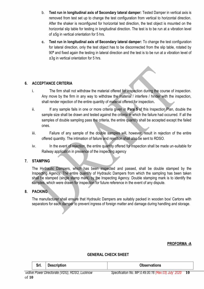
b. Test run in longitudinal axis of Secondary lateral damper: Tested Damper in vertical axis is
removed from test set up to change the test configuration from vertical to horizontal direction.
After the shaker is reconfigured for horizontal test direction, the test object is mounted on the
horizontal slip table for testing in longitudinal direction. The test is to be run at a vibration level
of ±5g in vertical orientation for 5 hrs.
c. Test run in longitudinal axis of Secondary lateral damper: To change the test configuration
for lateral direction, only the test object has to be disconnected from the slip table, rotated by
90º and fixed again the testing in lateral direction and the test is to be run at a vibration level of
±3g in vertical orientation for 5 hrs.
6. ACCEPTANCE CRITERIA
i. The firm shall not withdraw the material offered for inspection during the course of inspection.
Any move by the firm in any way to withdraw the material / interfere / hinder with the inspection,
shall render rejection of the entire quantity of material offered for inspection.
ii. If any sample fails in one or more criteria given in Para 5 of this Inspection Plan, double the
sample size shall be drawn and tested against the criteria in which the failure had occurred. If all the
samples of double sampling pass the criteria, the entire quantity shall be accepted except the failed
ones.
iii. Failure of any sample of the double samples will, however, result in rejection of the entire
offered quantity. The intimation of failure and rejection shall also be sent to RDSO.
iv. In the event of rejection, the entire quantity offered for inspection shall be made un-suitable for
Railway application in presence of the inspecting agency
7. STAMPING
The Hydraulic Dampers, which has been inspected and passed, shall be double stamped by the Inspecting Agency. The entire quantity of Hydraulic Dampers from which the sampling has been taken shall be stamped (single stamp mark) by the Inspecting Agency. Double stamping mark is to identify the samples, which were drawn for inspection for future reference in the event of any dispute.
8. PACKING
The manufacturer shall ensure that Hydraulic Dampers are suitably packed in wooden box/ Cartons with separators for each damper to prevent ingress of foreign matter and damage during handling and storage.
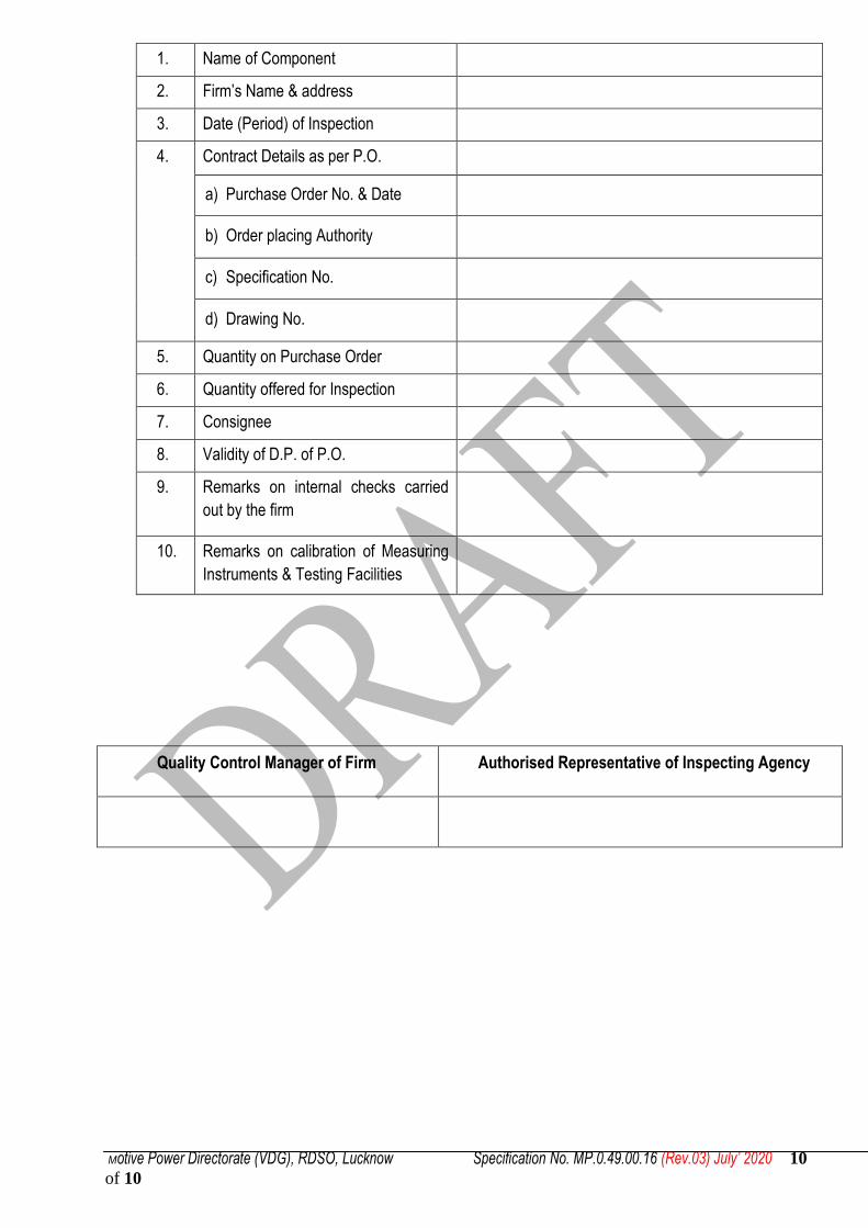
PROFORMA -A
GENERAL CHECK SHEET
Srl. Description Observations
Motive Power Directorate (VDG), RDSO, Lucknow Specification No. MP.0.49.00.16 (Rev.03) July’ 2020 10
of 10
1. Name of Component
2. Firm‟s Name & address
3. Date (Period) of Inspection
4. Contract Details as per P.O.
a) Purchase Order No. & Date
b) Order placing Authority
c) Specification No.
d) Drawing No.
5. Quantity on Purchase Order
6. Quantity offered for Inspection
7. Consignee
8. Validity of D.P. of P.O.
9. Remarks on internal checks carried
out by the firm
10. Remarks on calibration of Measuring
Instruments & Testing Facilities
Quality Control Manager of Firm Authorised Representative of Inspecting Agency

Motive Power Directorate (VDG), RDSO, Lucknow Specification No. MP.0.49.00.16 (Rev.03) July’ 2020 10 of 10
PROFORMA -B CHECK SHEET FOR TESTING FOR HYDRAULIC DAMPERS
1. Visual Check:
Drawing No. Lot Size
Sl. Description Checks Sample No. Remarks
1 2 3 4 5 6 7 8 9 10
1. Visual Check General workmanship
2. Free from welding defect General workmanship
3. Damper Oil Damper oil type, viscosity and amount of the damper oil
4. Surface finish of Piston Rod *
0.1 to 0.3 µm
5. Positive locking of Piston and piston Rod *
Proper locking of piston with piston ring to be ensured
6. Sealing Arrangement * Using low friction multiple sealing arrangement with better wiping properties , provision of additional dust lip etc.
7.
Surface protection:
I, Quality of primer High solid epoxy primers/ High solid alkyd primers (Firm to submit details).
ii. Thickness & Quality paint
Aliphatic polyurethane enamels or two part epoxy paint (Firm to submit details).
8. Identification Marking Manufacturer‟s name /code, Serial No., Type of Damper, Rated Capacity, Month & Year of manufacture, Drawing No
* S.No. 4, 5 & 6 shall be checked during prototype inspection & quality issues.
Motive Power Directorate (VDG), RDSO, Lucknow Specification No. MP.0.49.00.16 (Rev.03) July’ 2020 10 of 10
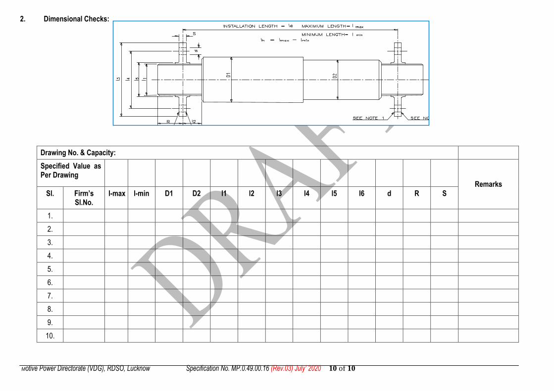
2. Dimensional Checks:
Drawing No. & Capacity:
Specified Value as Per Drawing
Remarks Sl. Firm’s
Sl.No. l-max l-min D1 D2 l1 l2 l3 l4 l5 l6 d R S
1.
2.
3.
4.
5.
6.
7.
8.
9.
10.

Motive Power Directorate (VDG), RDSO, Lucknow Specification No. MP.0.49.00.16 (Rev.03) July’ 2020 10 of 10
Sl. Drawing No. & Capacity:
Specified Value as per Drawing
Remarks
Firm’s Sl.No. L L1 L2 L3 L4 L5 L6
1.
2.
3.
4.
5.
6.
7.
8.
9.
10.

Motive Power Directorate (VDG), RDSO, Lucknow Specification No. MP.0.49.00.16 (Rev.03) July’ 2020 10 of 10
3. Strength Test & Damping Characteristics Test: Test procedure shall be followed as per procedure Para 5.3.2 of inspection plan and following data shall be recorded as followed:
4. Cardanic, Twisting Angle & Bushing Radial Stiffness Test Check
Testing of twisting, Cardanic angle and bushing radial Stiffness shall be done as per procedure mentioned in Para 5.3.4 of Inspection Plan and shall be recorded as under
Sl. Drawing No.
Specified Value as per Drawing Remarks
Firm’s Sl.No. Spheri Bloc Test
Twisting angle Cardanic angle *Bushing Radial stiffness
1.
2.
3.
4.
5.
* Bushing Radial Stiffness shall be checked during prototype inspection & quality issues.
Sr. No. Firm‟s sl. No. on dampers
Condition of damper before/after strength test
Specified damping force as per drawing
Observed Damping Force at Piston Velocities of 10 cm/sec
Remarks on Damper characteristics (Attach graph)
Oil leakage/physical damage (Yes/No)
Remarks
Compression %age change Expansion
%age change
1. Before
After
2.
Before
After
3.
Before
After
4.
Before
After
5.
Before
After
Motive Power Directorate (VDG), RDSO, Lucknow Specification No. MP.0.49.00.16 (Rev.03) July’ 2020 10 of 10
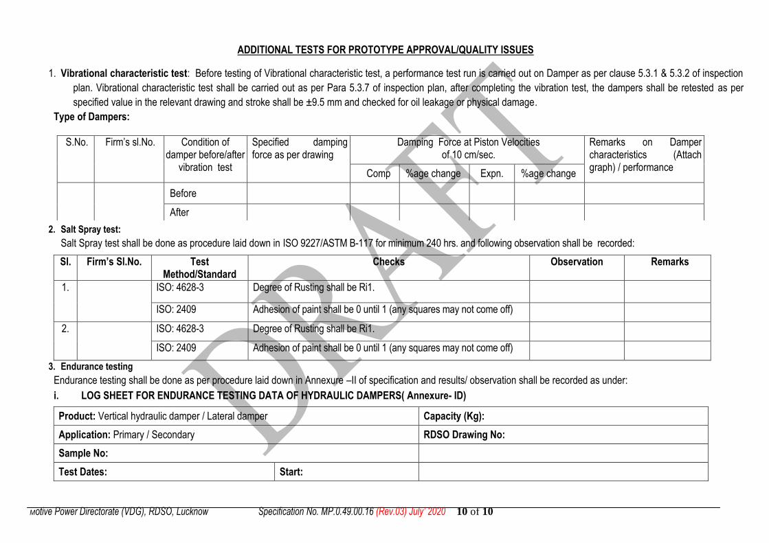
ADDITIONAL TESTS FOR PROTOTYPE APPROVAL/QUALITY ISSUES
1. Vibrational characteristic test: Before testing of Vibrational characteristic test, a performance test run is carried out on Damper as per clause 5.3.1 & 5.3.2 of inspection
plan. Vibrational characteristic test shall be carried out as per Para 5.3.7 of inspection plan, after completing the vibration test, the dampers shall be retested as per
specified value in the relevant drawing and stroke shall be ±9.5 mm and checked for oil leakage or physical damage.
Type of Dampers: 2. Salt Spray test:
Salt Spray test shall be done as procedure laid down in ISO 9227/ASTM B-117 for minimum 240 hrs. and following observation shall be recorded:
Sl. Firm’s Sl.No. Test Method/Standard
Checks Observation Remarks
1. ISO: 4628-3 Degree of Rusting shall be Ri1.
ISO: 2409 Adhesion of paint shall be 0 until 1 (any squares may not come off)
2. ISO: 4628-3 Degree of Rusting shall be Ri1.
ISO: 2409 Adhesion of paint shall be 0 until 1 (any squares may not come off)
3. Endurance testing
Endurance testing shall be done as per procedure laid down in Annexure –II of specification and results/ observation shall be recorded as under:
i. LOG SHEET FOR ENDURANCE TESTING DATA OF HYDRAULIC DAMPERS( Annexure- ID)
Product: Vertical hydraulic damper / Lateral damper Capacity (Kg):
Application: Primary / Secondary RDSO Drawing No:
Sample No:
Test Dates: Start:
S.No. Firm‟s sl.No. Condition of damper before/after
vibration test
Specified damping force as per drawing
Damping Force at Piston Velocities of 10 cm/sec.
Remarks on Damper characteristics (Attach graph) / performance
Comp %age change Expn. %age change
Before
After
Motive Power Directorate (VDG), RDSO, Lucknow Specification No. MP.0.49.00.16 (Rev.03) July’ 2020 10 of 10
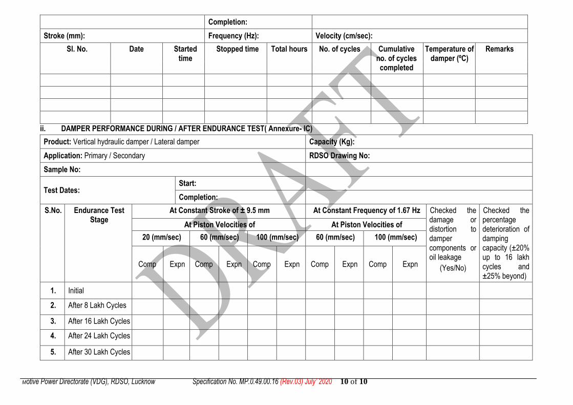
Completion:
Stroke (mm): Frequency (Hz): Velocity (cm/sec):
Sl. No. Date Started time
Stopped time Total hours No. of cycles Cumulative no. of cycles completed
Temperature of damper (ºC)
Remarks
ii. DAMPER PERFORMANCE DURING / AFTER ENDURANCE TEST( Annexure- IC)
Product: Vertical hydraulic damper / Lateral damper Capacity (Kg):
Application: Primary / Secondary RDSO Drawing No:
Sample No:
Test Dates: Start:
Completion:
S.No. Endurance Test Stage
At Constant Stroke of ± 9.5 mm At Constant Frequency of 1.67 Hz Checked the damage or distortion to damper components or oil leakage
(Yes/No)
Checked the percentage deterioration of damping capacity (±20% up to 16 lakh cycles and ±25% beyond)
At Piston Velocities of At Piston Velocities of
20 (mm/sec) 60 (mm/sec) 100 (mm/sec) 60 (mm/sec) 100 (mm/sec)
Comp Expn Comp Expn Comp Expn Comp Expn Comp Expn
1. Initial
2. After 8 Lakh Cycles
3. After 16 Lakh Cycles
4. After 24 Lakh Cycles
5. After 30 Lakh Cycles