Technical specification for the procurement of the LV...
28
Technical specification for the procurement of the LV power supply system for the MDT detector of the ATLAS experiment Technical responsibles of the specification: Dr. M. Beretta ([email protected] ) and Dr. A. Lanza ([email protected] ) Page 1 of 28 Technical specification for the procurement of the LV power supply system for the MDT detector of the ATLAS experiment The present document defines the technical specification of the Low Voltage (LV) power supply system for the MDT chambers of the ATLAS experiment, which will be operational from 2006 on the proton-proton beam of the new LHC accelerator at CERN. The present specification requires the supply of: 1- 596 LV channels, with output voltage from 5 to 7 V and output current up to 25 A, working in radiation and magnetic field environment, based on DC-DC converters. They must be available as modules with modularity of 2, 4 or 6 channels each; 2- For the above mentioned channels, 51 19” crates, working in radiation and magnetic field environment, if modularity is 2 channels/module. Depth must be less than 460 mm for 16 crates, and can reach up to 700 mm for the remaining 35. Otherwise, if modularity is 4 – 6 channels/module, 20 19” crates, working in radiation and magnetic field environment. Depth must be less than 460 mm for 5 crates, and can reach up to 700 mm for the remaining 15. In both cases, all crates can have the same depth of 460 mm; 3- All remote controllers necessary to control and monitor 51 crates, if modularity is 2 channels/module, or 20 crates, if modularity is 4 - 6 channels/module; 4- optionally, 1 primary generator system for supplying all modules, working in non-hostile environment and able to provide a total output power of 90 kW. The system must be composed of units that fit in standard 19” racks, with output power in the range 5 – 8 kW each one.
Transcript of Technical specification for the procurement of the LV...

Technical specification for the procurement of the LV power supply system for the MDT detector of the ATLAS experiment
Technical responsibles of the specification: Dr. M. Beretta ([email protected]) and Dr. A. Lanza ([email protected])
Page 1 of 28
Technical specification for the procurement of the LV power supply
system for the MDT detector of the ATLAS experiment
The present document defines the technical specification of the Low Voltage (LV) power
supply system for the MDT chambers of the ATLAS experiment, which will be operational
from 2006 on the proton-proton beam of the new LHC accelerator at CERN.
The present specification requires the supply of:
1- 596 LV channels, with output voltage from 5 to 7 V and output current up to 25
A, working in radiation and magnetic field environment, based on DC-DC
converters. They must be available as modules with modularity of 2, 4 or 6 channels
each;
2- For the above mentioned channels, 51 19” crates, working in radiation and
magnetic field environment, if modularity is 2 channels/module. Depth must be less
than 460 mm for 16 crates, and can reach up to 700 mm for the remaining 35.
Otherwise, if modularity is 4 – 6 channels/module, 20 19” crates, working in
radiation and magnetic field environment. Depth must be less than 460 mm for 5
crates, and can reach up to 700 mm for the remaining 15. In both cases, all crates can
have the same depth of 460 mm;
3- All remote controllers necessary to control and monitor 51 crates, if modularity is 2
channels/module, or 20 crates, if modularity is 4 - 6 channels/module;
4- optionally, 1 primary generator system for supplying all modules, working in
non-hostile environment and able to provide a total output power of 90 kW. The
system must be composed of units that fit in standard 19” racks, with output power
in the range 5 – 8 kW each one.

Technical specification for the procurement of the LV power supply system for the MDT detector of the ATLAS experiment
Technical responsibles of the specification: Dr. M. Beretta ([email protected]) and Dr. A. Lanza ([email protected])
Page 2 of 28
Contents 1. Introduction
1.1 The I.N.F.N. 1.2 The CERN 1.3 The LHC accelerator 1.4 The ATLAS experiment 1.5 Subject of the procurement
2. The MDT detector
2.1 Detector layout 2.2 Environmental operating conditions
3. System specification
3.1 General description 3.2 LV distributor
3.2.1 Functionality 3.2.2 Mechanical requirements 3.2.3 Electrical requirements
3.3 Crate requirements 3.4 Remote controller requirements 3.5 Primary VDC generator system requirements
4. Documentation and Quality Control
4.1 Conformities and documentation provided by the Supplier 4.2 Radiation and magnetic field policy 4.3 Tests and acceptance criteria
4.3.1 Tests to be performed by the Supplier 4.3.2 Tests to be performed by I.N.F.N.
4.4 Maintenance at CERN during operation 5. Pre-series and series productions
5.1 Pre-series production quantities 5.2 Series production quantities
6. Shipment and delivery schedule
6.1 Shipment address 6.2 Delivery time schedule 6.3 Provisional acceptance
7. Offer
Technical specification for the procurement of the LV power supply system for the MDT detector of the ATLAS experiment
Technical responsibles of the specification: Dr. M. Beretta ([email protected]) and Dr. A. Lanza ([email protected])
Page 3 of 28
1. Introduction
1.1 The I.N.F.N.
The I.N.F.N. (Istituto Nazionale di Fisica Nucleare) is an Italian institute that promotes,
coordinates and funds fundamental research mainly in the fields of high-energy, nuclear
and theoretical physics. Groups from the universities of Rome, Padua, Turin, and Milan founded the I.N.F.N. on
August 8, 1951 for the purpose of building upon the scientific tradition established during
the 1930’s by Enrico Fermi and his school, with their theoretical and experimental research
in nuclear physics.
During the latter half of the 1950’s, the I.N.F.N. designed and constructed the first Italian
accelerator, the electron synchrotron developed in Frascati, the birthplace of the Institute’s
first national laboratory.
During the same period, the I.N.F.N. began to participate in research into the
construction and use of ever-more powerful accelerators being conducted at CERN.
Today, I.N.F.N. researchers make important contributions to research not only in various
European laboratories, but also in numerous research centers worldwide.
1.2 The CERN
The CERN is a European organization of 20 member states. Its seat is in Switzerland, in
Geneva, but a part of it also extends beyond the French border. Its aim is to offer the most
up-to-date particle accelerators and their experimental zones to the international
community of physicists .
At present, its laboratories and installations are used by more than 5000 physicists of
research institutes of all continents .
Technical specification for the procurement of the LV power supply system for the MDT detector of the ATLAS experiment
Technical responsibles of the specification: Dr. M. Beretta ([email protected]) and Dr. A. Lanza ([email protected])
Page 4 of 28
1.3 The LHC accelerator
The Large Hadron Collider (LHC) is the accelerator under construction at CERN. It will
accelerate and collide two proton beams of 7 TeV energy. The LHC is now in the
installation phase in the 27 km long tunnel, 100 m underground, which hosted the LEP
(Large Electron Positron) accelerator until 2000. The very big collision energy reached by
protons is possible tanks to the use of superconducting magnets, working at the liquid
Helium temperature.
The LHC will be operational from end 2007.
1.4 The ATLAS experiment
The ATLAS (A Toroidal Lhc ApparatuS) experiment aims to study the particle
interactions produced by collisions in the LHC accelerator, measuring the momentum and
energy of the particles produced by the above-mentioned collisions. It is formed by an
international collaboration of roughly 2000 physicists, belonging to research centers of 34
countries of the five continents.
The experiment is composed of many detectors, and has a cylindrical shape, as shown in
Fig. 1. It is placed in a cavern and surrounded by scaffolding (partially shown in Fig. 1),
which host all electronics and gas racks and allow access to the detectors by means of
platforms.
The most external part of the experiment is the muon apparatus, composed of four
different detectors. The LV system, specified in the present document, is used to supply the
MDT (Monitored Drift Tube chambers) detector front-end electronics, which with its 5000
m2 of drift tubes will be able to measure the position of a particle with a precision of 50
microns.
Each MDT chamber is composed of aluminum tubes with a diameter of 30 mm, from 1 m
up to 6 m long, with a Tungsten wire of 50 micron diameter stretched on the central axis.
From 12 up to 72 tubes are glued one to each other forming plane layers, which in turn,
glued together by three or four, form a structure called multilayer.
Technical specification for the procurement of the LV power supply system for the MDT detector of the ATLAS experiment
Technical responsibles of the specification: Dr. M. Beretta ([email protected]) and Dr. A. Lanza ([email protected])
Page 5 of 28
One MDT chamber is composed of two multilayers, separated by an aluminum spacer.
1.5 Subject of the procurement
The present document is intended for procurement of the MDT LV system. Subject of this
technical specification are the following components:
1 – 596 LV channels, with output voltage from 5 to 7 V and output current up to 25 A,
working in radiation and magnetic field environment, based on DC-DC converters.
They must be available as modules with modularity of 2, 4 or 6 channels each;
2 – For the above mentioned channels, 51 19” crates, working in radiation and magnetic
field environment, if modularity is 2 channels/module. Depth must be less than 460
mm for 16 crates, and can reach up to 700 mm for the remaining 35. Otherwise, if
modularity is 4 – 6 channels/module, 20 19” crates, working in radiation and
magnetic field environment. Depth must be less than 460 mm for 5 crates, and can reach
up to 700 mm for the remaining 15. In both cases, all crates can have the same depth of
460 mm;
3 – All remote controllers necessary to control and monitor 51 crates, if modularity is 2
channels/module, or 20 crates, if modularity is 4-6 channels/module;
4 – optionally, 1 primary generator system for supplying all modules, working in non-
hostile environment and able to provide a total output power of 90 kW. The system
must be composed of units that fit in standard 19” racks, with output power in the
range 5 – 8 kW each one.
Technical specification for the procurement of the LV power supply system for the MDT detector of the ATLAS experiment
Technical responsibles of the specification: Dr. M. Beretta ([email protected]) and Dr. A. Lanza ([email protected])
Page 6 of 28
2 – The MDT detector
2.1 Detector layout
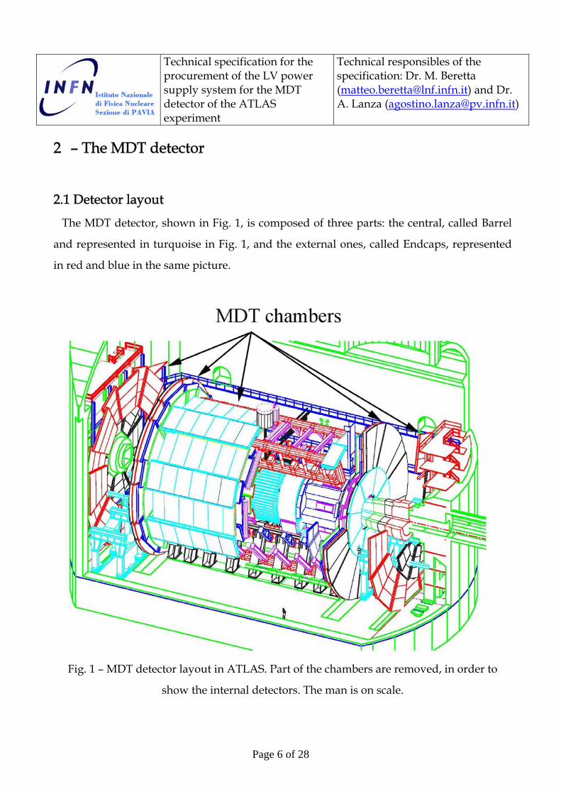
The MDT detector, shown in Fig. 1, is composed of three parts: the central, called Barrel
and represented in turquoise in Fig. 1, and the external ones, called Endcaps, represented
in red and blue in the same picture.
Fig. 1 – MDT detector layout in ATLAS. Part of the chambers are removed, in order to
show the internal detectors. The man is on scale.

Technical specification for the procurement of the LV power supply system for the MDT detector of the ATLAS experiment
Technical responsibles of the specification: Dr. M. Beretta ([email protected]) and Dr. A. Lanza ([email protected])
Page 7 of 28
Endcaps are in turn composed of three “wheels”, of which the most internal, called Small
Wheel, is the smallest (not visible in Fig. 1), and the most external, called External or Outer
Wheel, is the biggest (shown in red in Fig. 1). The wheel shown in blue in Fig. 1 is called
Big Wheel. Barrel MDTs are of rectangular shape, while the Endcap ones are of trapezoidal
shape.
MDT chambers are composed of a variable number of proportional tubes, according to
the type. They are filled in with a gas mixture of Ar and CO2, in proportion of 93 to 7, at 3
absolute bar, and are flown at a rate of 1 volume exchange per day. Wires are polarized at
3.08 kV positive with respect to tubes, which are the chamber electrical ground.
MDT LV System
US15
LV MAIN LV MAIN CONTROLLERCONTROLLER
LV MAIN LV MAIN CONTROLLERCONTROLLER
USA15
1172 MDT Chambers
UX15(hostile area)
LV MAIN LV MAIN POWER SUPPLYPOWER SUPPLY
LV Local LV Local Distributors Distributors
Endcaps
Barrel
ACLine
DCS
DCS
5V DC Cables bundle(one for each chamber)
Control Cables
IntermediateVDC Cables
5V DC Cables bundle(one for each chamber)
Fig. 2 - Low Voltage Power Supply System diagram

Technical specification for the procurement of the LV power supply system for the MDT detector of the ATLAS experiment
Technical responsibles of the specification: Dr. M. Beretta ([email protected]) and Dr. A. Lanza ([email protected])
Page 8 of 28
MDT chambers are in total 1172, subdivided in:
• 656 belonging to Barrel;
• 516 belonging to Endcaps;
as shown in Fig.2.
Due to the their different dimensions, chambers are equipped with a different number of
front-end (analog and digital) electronic boards, called mezzanines, on which there are low
drop voltage regulators for both analog and digital parts. Current consumption for each
mezzanine is around 400 mA.
All mezzanines belonging to one chamber are readout by one (digital) electronic board,
called CSM, Chamber Service Module, with a current consumption of 1 A.
MDT chambers have different sizes, and consequently different current consumptions,
ranging from 5 A for the smallest type up to 9 A for the biggest type of chamber.
In order to optimize currents and financial resources, each LV channel has to supply two
MDT chambers, so needed currents are in the range 10 – 20A, fitting quite well with what is
available on the market. The minimum current that must be supplied by each LV channel can be estimated
applying a safety factor of 30% to the consumption currents for each chamber type. It has to
be underlined that small chambers require approximately one half of the current than big
chambers, so in order to minimize the use of over-dimensioned LV modules, chambers can
be subdivided into two groups, respectively requiring LV channels with currents up to 15A
and up to 25A. Summing up on all chambers, the total number of LV channels with current
lower than 15A and lower than 25 A is shown in Table 1.
LV channels with current < 15A
LV channels with current < 25A
Barrel 123 205 Endcaps 24 224 Total 147 429 Tab. 1 – LV channels with current up to 15A and up to 25A

Technical specification for the procurement of the LV power supply system for the MDT detector of the ATLAS experiment
Technical responsibles of the specification: Dr. M. Beretta ([email protected]) and Dr. A. Lanza ([email protected])
Page 9 of 28
Power consumption of the front-end and readout electronics of the whole MDT detector,
supposing an average input voltage to the electronics of 5 V, is 35.5 kW. Including power
loss in cables, as described in section 3.1, it increases to 40 kW. Taking a safety factor of 30%
more for the supplied current, the power delivered by the distributors is 52 kW, and
assuming a conversion efficiency of at least 70% for the distributors under operating
conditions, the power supplied by the primary generator system must be 67 kW. Taking in
consideration a 30% increase for the necessary margin on primary generator current, the
total power consumption of the LV system can be estimated around 87 kW. The target
value is assumed to be 90 kW.
2.2 Environmental operating requirements
The LV system is composed of three main blocks, called distributors, remote controllers
and primary generators, which functionality and performance will be detailed in the
following.
Distributors are placed in racks situated on the scaffolding surrounding ATLAS, as
shown in Figs. 3 and 4, respectively for the side of the ATLAS electronics hall, called
USA15, and for the opposite side, where there is another hall called US15. The two Big
Wheels and the two External Wheels (the blue and red chambers in Fig. 1) are exceptions,
having the racks placed on the rim of the wheels.
Available racks Rack height Crates/rack Total Barrel 7 41U 4 Small Wheels 2 41U 4
9
Big Wheels 8 19U 2 External Wheels 8 19U 2
16
Tab. 2 – Summary of available racks

Technical specification for the procurement of the LV power supply system for the MDT detector of the ATLAS experiment
Technical responsibles of the specification: Dr. M. Beretta ([email protected]) and Dr. A. Lanza ([email protected])
Page 10 of 28
TID (Gray/10 years)
NIEL (1 MeV equivalent neutrons/(cm2*10
years))
SEE (>20 MeV hadrons/(cm2*10
years)) B field (Tesla)
Safety factor simulation 3,5 5 5
Safety factor low dose rate 5 1 1
Safety factor production lot 4 4 4
Total safety factors 70 20 20
Barrel and Small Wheel 186 1,2*1012 2,7*1011 0,1
Big Wheel 63 8,8*1011 2,2*1011 0,1
Tab. 3 – Summary of radiation and B field requirements for LV distributors
Fig. 3 – Electronics rack positions around the detector, USA side

Technical specification for the procurement of the LV power supply system for the MDT detector of the ATLAS experiment
Technical responsibles of the specification: Dr. M. Beretta ([email protected]) and Dr. A. Lanza ([email protected])
Page 11 of 28
For Barrel and Small Wheels, the height of electronics racks is 41U. For the Big and the
External Wheels, each rack has to host only two crates and the cooling system, so their
height is limited to 19U. Table 2 summarizes the number of available racks for the detector
subsystems.
The distance between electronics racks and the interaction point is 12 meters on average.
At this position there is a not negligible radiation. Simulations show up that the most
intense dose is between the end of the Barrel and the Big Wheels, where the interposed
material is thinner.
Fig. 4 – Electronics rack positions around the detector, US side
Technical specification for the procurement of the LV power supply system for the MDT detector of the ATLAS experiment
Technical responsibles of the specification: Dr. M. Beretta ([email protected]) and Dr. A. Lanza ([email protected])
Page 12 of 28
Estimations of radiation take in account three different safety factors: one for simulation
uncertainties, one for the low dose rate correction and one for the spread of different
production lots of used integrated circuits.
Table 3 summarizes the maximum radiation levels predicted for the rack positions, and
the safety factors used. All LV distributors must be able to work at worst values without
any damage.
Because of the toroidal magnet embedded in the MDT detector (the red coils in Fig. 1),
electronics racks are also immersed in a quite intense magnetic field. The simulated upper
limit is 0.1 T, as reported in Table 3. All LV distributors and the related crates must be able
to cope with such environment.
In particular, crate cooling systems cannot be based on standard fan units, due to the
presence of high magnetic field.
Two options are feasible:
- crates are cooled by means of water, circulating in pipes properly embedded in
them;
- crates are cooled by means of the mixed air-water system developed by a CERN
group, a description of which is available at
http://documents.cern.ch//archive/electronic/cern/groupdoc/epess/public/epes
s-2003-014.pdf, and
https://edms.cern.ch/file/336025/1/racks_tests_magnetiques.pdf.
This last option is the preferred one. It will be detailed in section 3.3.
3 – System specification
3.1 General description
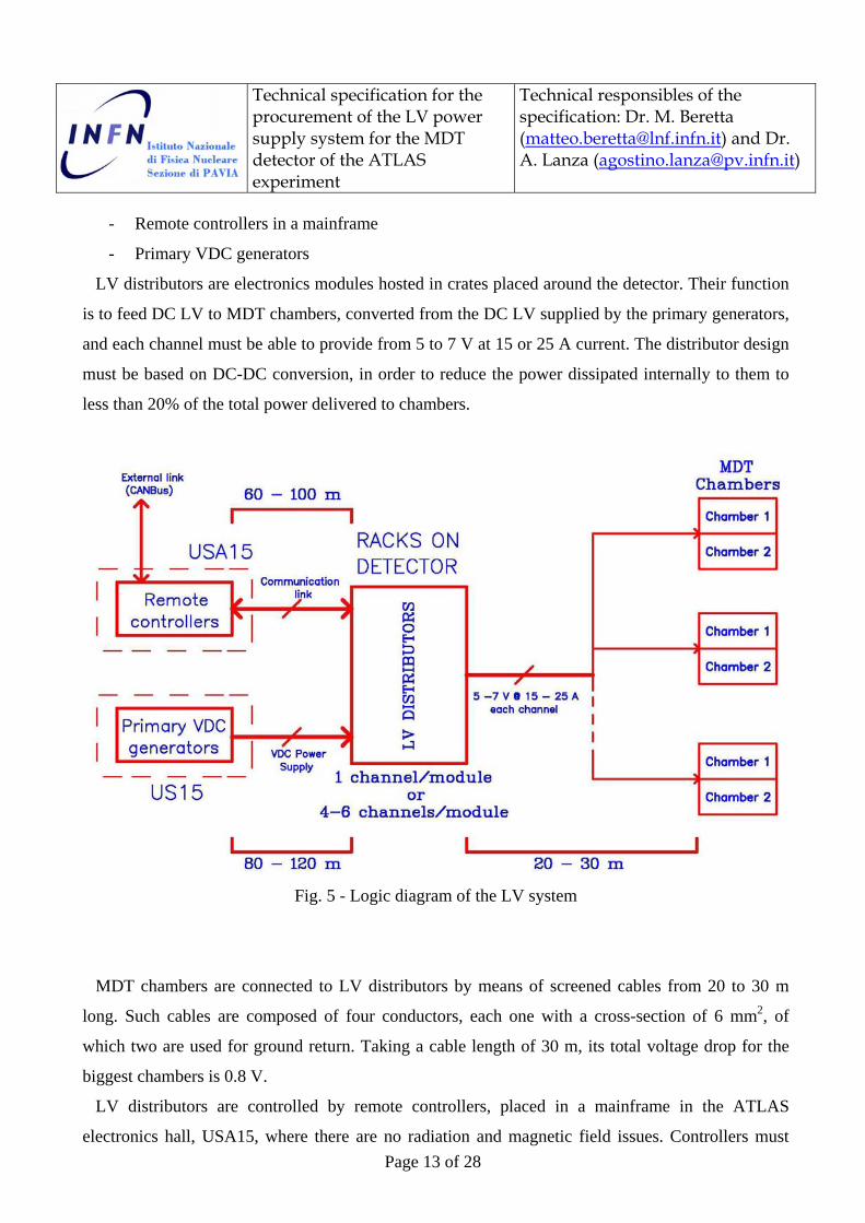
The logic diagram of the LV system is illustrated in Fig. 5. It is composed of three blocks:
- LV distributors and hosting crates
Technical specification for the procurement of the LV power supply system for the MDT detector of the ATLAS experiment
Technical responsibles of the specification: Dr. M. Beretta ([email protected]) and Dr. A. Lanza ([email protected])
Page 13 of 28
- Remote controllers in a mainframe
- Primary VDC generators
LV distributors are electronics modules hosted in crates placed around the detector. Their function
is to feed DC LV to MDT chambers, converted from the DC LV supplied by the primary generators,
and each channel must be able to provide from 5 to 7 V at 15 or 25 A current. The distributor design
must be based on DC-DC conversion, in order to reduce the power dissipated internally to them to
less than 20% of the total power delivered to chambers.
Fig. 5 - Logic diagram of the LV system
MDT chambers are connected to LV distributors by means of screened cables from 20 to 30 m
long. Such cables are composed of four conductors, each one with a cross-section of 6 mm2, of
which two are used for ground return. Taking a cable length of 30 m, its total voltage drop for the
biggest chambers is 0.8 V.
LV distributors are controlled by remote controllers, placed in a mainframe in the ATLAS
electronics hall, USA15, where there are no radiation and magnetic field issues. Controllers must
Technical specification for the procurement of the LV power supply system for the MDT detector of the ATLAS experiment
Technical responsibles of the specification: Dr. M. Beretta ([email protected]) and Dr. A. Lanza ([email protected])
Page 14 of 28
initialize and monitor the distributors. They are linked to distributors by means of screened copper
cables, from 60 to 100 meters long. Controllers are linked to the ATLAS central Detector Control
System (DCS) via an Ethernet or CANBus connection, which must be available on the mainframe.
Primary VDC generators provide the DC current necessary to supply the electronics of the LV
distributors, and to feed them the power for generating the DC LV. They must be based on switching
AC-DC converters, in order to reduce dimensions, weight and costs. Primary generators are
accommodated in a hall (US15) on the other side of the experiment with respect to the electronics
hall USA15, where the environmental conditions are the same as USA15. The distance between
them and the distributors is between 80 and 120 meters, and connection cables are similar to the
ones used between distributors and chambers, but with a bigger cross-section (34 mm2), in order to
avoid voltage drops greater than 1 V.
3.2 LV distributor
3.2.1 Functionality
LV distributors generate and supply power to MDT chamber electronics. So, they have to
be fully manageable from a remote mainframe. Modularity can be either 2 or 4 or 6
channels per module, depending on the total current available at the output. The Supplier
must offer a configuration that minimizes, in order of priority:
- the total cost;
- the power consumption internal to the modules;
- the occupancy space.
The number of channels shown in Table 3, 147 requiring modules with 15 A output
current and 429 requiring modules with 25 A output current, is what needed in order to
supply the whole MDT detector, while the number of channels reported in section 1.5, 596,
takes in account some spares, which must be used for destructive radiation tests. The
Supplier can choose either a single or a mixed modularity for all 596 channels, proposing
one of the following solutions:
1 - 298 2-channel modules, each one with output current equal or greater than 25 A;

Technical specification for the procurement of the LV power supply system for the MDT detector of the ATLAS experiment
Technical responsibles of the specification: Dr. M. Beretta ([email protected]) and Dr. A. Lanza ([email protected])
Page 15 of 28
2 - 149 4-channel modules, with each channel able to supply an output current equal to
or greater than 25 A;
3 - 26 6-channel modules, with each channel able to supply an output current between
15 and 20 A, plus 110 4-channel modules, with each channel able to supply an
output current equal to or greater than 25 A.
The main functionality requirements are listed in Table 4, and illustrated in the following.
Voltage and current settings, including the maximum allowed voltage limit, Vmax, should
be set locally by means of a trimmer, software programmability is not required.
Local hardware Vset Yes
Remote software Vset No
Local hardware Iset Yes
Remote software Iset No
Local hardware Vmax Yes
Remote software Vmax No Trip logic Yes Overcurrent reaction Channel is switched offOvervoltage reaction Channel is switched offSense wires No Impedance local adjustment Yes
Vset monitoring No
Vout monitoring Yes
Iset monitoring No
Iout monitoring Yes
Vmax monitoring No Programmable ramp up/down No Radiation performance See section 2.2 B field performance See section 2.2
Table 4 – LV distributor functionality
Trip logic must be implemented, in order to safely protect the detector against
malfunctioning and accidents. In particular, when an overvoltage or an overcurrent event
is detected, LV distributors must be switched off after a time set by the trip value.

Technical specification for the procurement of the LV power supply system for the MDT detector of the ATLAS experiment
Technical responsibles of the specification: Dr. M. Beretta ([email protected]) and Dr. A. Lanza ([email protected])
Page 16 of 28
Sense wires are not allowed, for reasons of costs and space limitations, but voltage drop
along the cables connecting distributors to chambers is not negligible, so the output voltage
should be regulated in such a way to take in account the cable voltage drop.
All output voltages and currents have to be monitored, together with other main
functional parameters, but all setting voltages and currents don’t need to be remotely
monitored
Ramp up and ramp down parameters should be fixed in hardware, without any remote
programmability. Their values are chosen so to protect the load against voltage spikes.
Distributors must be operational in radiation and magnetic field environment, as already
detailed in section 2.2.
3.2.2 Mechanical requirements
LV distributors are electronic modules placed in 19” crates. The minimum number of
channels hosted in a single crate must be 20, so, taking in account the possible modularities
above described, the maximum width of the single module should not exceed 16 HP (81.28
mm)
Module height can be either the standard single Europa (3U) or the double Europa (6U),
in order to allow at least up to 4 crates to be put in a 41U rack. Because of the available rack
depth of 700 mm, its maximum depth must not exceed 430 mm, in order to leave enough
space for backplanes and possible auxiliary electronics on the back of crates.
Maximum height 6 U Maximum width 16 HP Maximum depth 430 mm Channels/module 2, 4 or 6 LV output connector bananas or screws on front panel Monitoring/control and LV connectors No requirements
"Channel ON" signaling One/channel on front panel Power interlock On front panel Tab. 5 – LV distributor mechanical requirements
Technical specification for the procurement of the LV power supply system for the MDT detector of the ATLAS experiment
Technical responsibles of the specification: Dr. M. Beretta ([email protected]) and Dr. A. Lanza ([email protected])
Page 17 of 28
Crates are unaccessible from rear, so all connections should be put on the front panel. In
particular, the power connectors should be of banana or screw type, and must be available
on the front panel. Other connectors, used for monitoring/control and for input power
supply, can be on the back side, if buses are used for them, but master connectors must be
available on the front side at crate level.
Close to each output connector on the front panel, there must be a LED indicating that the
channel is ON.
For each module, it has to be available on the front panel an interlock switch, in order to
hardware enable the module.
Table 5 summarizes the LV distributor mechanical requirements.
3.2.3 Electrical requirements
LV distributors are required to continuously operate from 5 to 7 V, supplying
approximately 70% of their maximum available current, 25 A or more. For 156 channels, as
explained in section 3.2.1, it can be 15 A.
Output voltage and current accuracies are intended as the difference between the
monitored and the real values. Output voltage accuracy must be within 0.3% Full Scale
(FS), while output current accuracy must be within 2% FS.
Maximum ripple in all the bandwidth of interest, 40 MHz, must be lower than 20 mV.
Voltage and current sets must include all available range, from 5 to 7 V.
Ramp up and ramp down are fixed in harwdare. Their recommended value is 1 ms.
Trip feature must be programmable, possibly in steps of 0.1 s.
Channel ground must be floating. MDT electronics only needs positive voltage, but
reference voltage must be disconnected from case and earth in order to avoid ground
loops.
All communications links must be optically decoupled. The breakdown voltage of the
optocouplers must be at least 100 V.
Channel stability in temperature and over long term must not exceed 1000 ppm/ºC and
1000 ppm/month.

Technical specification for the procurement of the LV power supply system for the MDT detector of the ATLAS experiment
Technical responsibles of the specification: Dr. M. Beretta ([email protected]) and Dr. A. Lanza ([email protected])
Page 18 of 28
Conversion efficiency must be greater than 70% in full operation, at maximum current
and in 0.1 T magnetic field.
Table 6 illustrates the LV distributor electrical requirements.
Vout range 5 - 7 V floating
Iout output range 0 - 25 A (for 156 channels can be 0 – 15 A)
Vout accuracy ± 0.3% FS
Iout accuracy ± 2% FS Differential ripple < 20 mVpp from 0 to 40 MHz Vset range 5 - 7 V hardware
Iset range 0 - 25 A hardware (0 - 15 A for 156 channels)
Vmon resolution 50 mV
Imon resolution 50 mA Ramp up/down 1 ms fixed Transient response 1 Vpp, 1 µs Trip resolution 0.1 s Ground Floating Communications line decoupling Optical, with Vbreakdown > 100V Temperature stability 1000 ppm/°C Long term stability 1000 ppm/month Conversion efficiency > 70% at full load and 0.1 T B field
Tab. 6 – LV distributor electrical requirements
3.3 Crate requirements
Crates are based on the standard Europa chassis, 19” large, and can be 3U or 6U high,
depending on the modularity of the system. Maximum depth depends on their position, as
shown in Table 7. Crate depth on External and Big Wheels is limited by the available space.
Barrel and Small Wheel crates can be up to 700 mm deep, but there is no constraint for
getting them of the same depth as for the two wheels.
No ventilation unit must be embedded in crates. Their cooling must be done using one of
the two following options:
A – water cooling by means of copper pipes embedded in crates. If this option is used, the
total crate height, including cooling pipes, must not exceed 8U. Pipes must be terminated
Technical specification for the procurement of the LV power supply system for the MDT detector of the ATLAS experiment
Technical responsibles of the specification: Dr. M. Beretta ([email protected]) and Dr. A. Lanza ([email protected])
Page 19 of 28
with ½” nuts. Cooling water circuit is available at each rack position, and it must be taken
in account that pressure of circulating water will be kept below 1 bar for safety reasons;
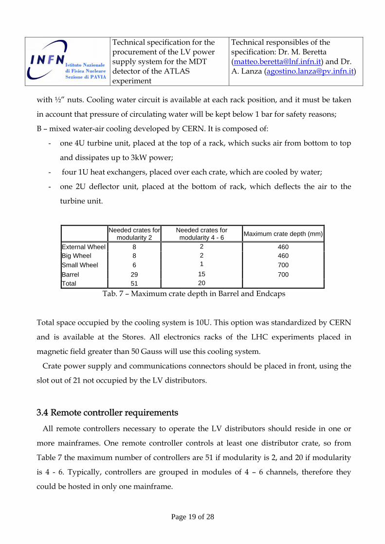
B – mixed water-air cooling developed by CERN. It is composed of:
- one 4U turbine unit, placed at the top of a rack, which sucks air from bottom to top
and dissipates up to 3kW power;
- four 1U heat exchangers, placed over each crate, which are cooled by water;
- one 2U deflector unit, placed at the bottom of rack, which deflects the air to the
turbine unit.
Needed crates for modularity 2
Needed crates for modularity 4 - 6 Maximum crate depth (mm)
External Wheel 8 2 460 Big Wheel 8 2 460 Small Wheel 6 1 700 Barrel 29 15 700 Total 51 20
Tab. 7 – Maximum crate depth in Barrel and Endcaps
Total space occupied by the cooling system is 10U. This option was standardized by CERN
and is available at the Stores. All electronics racks of the LHC experiments placed in
magnetic field greater than 50 Gauss will use this cooling system.
Crate power supply and communications connectors should be placed in front, using the
slot out of 21 not occupied by the LV distributors.
3.4 Remote controller requirements
All remote controllers necessary to operate the LV distributors should reside in one or
more mainframes. One remote controller controls at least one distributor crate, so from
Table 7 the maximum number of controllers are 51 if modularity is 2, and 20 if modularity
is 4 - 6. Typically, controllers are grouped in modules of 4 – 6 channels, therefore they
could be hosted in only one mainframe.

Technical specification for the procurement of the LV power supply system for the MDT detector of the ATLAS experiment
Technical responsibles of the specification: Dr. M. Beretta ([email protected]) and Dr. A. Lanza ([email protected])
Page 20 of 28
Remote controllers are placed in a non-hostile environment, USA15, and are linked to
distributor crates by means of control cables, each one 60 – 100 meters long. The
implemented hardware protocol must be able to communicate without errors using cables
of at least 120 meters long.
The mainframe must be equipped with an Ethernet port or with a CANBus port. It can
operate the system either standalone, by means of embedded display and keyboard, or
with the aid of a PC.
3.5 Primary VDC generator system requirements
LV distributors are fed by an AC-DC generator system. It must be composed of more
than one unit, in order to increase system granularity and avoid higher currents on
connecting cables, so big voltage drop on them. Primary generators are connected to each
distributor crate by means of screened cables with a section of 34 mm2.
The primary generator chassis must be of rack type, 19” large. Its dimensions must not
exceed 9U in height and 700 mm in depth, including the requested cooling unit
(ventilation fans).
Output voltage must be compatible with the requirements of the LV distributors.
Chassis Rack type, 19" Unit max dimensions 9U (height) x 700 mm (depth) Cooling Embedded or external fan unit Output voltage Compatible with the LV distributor input Unit output power From 5 to 8kW Output connectors Screw and nuts (preferred) AC input voltage 415 VAC 50 Hz 2P+N+E AC mains plug IEC 309 standard Load/line regulation and stability in time
Compatible with the LV distributor technical specifications
Tab. 8 – Requirements of primary VDC generator system
Output connectors should be made of screw and nuts, so cable connectors can be simple
cable lugs.
Technical specification for the procurement of the LV power supply system for the MDT detector of the ATLAS experiment
Technical responsibles of the specification: Dr. M. Beretta ([email protected]) and Dr. A. Lanza ([email protected])
Page 21 of 28
Preferred AC input voltage is three phases 415 VAC, 50 Hz, plus Neutral and Earth, for
which mains plug should be of IEC 309 standard. Single phase units, if available, can be
quoted as well.
All electrical specification must comply with the LV distributor specification. Table 8
summarizes the primary generator requirements.
4 – Documentation and Quality Control
4.1 Conformities and documentation provided by the Supplier
Components subject of the present document must conform to all specified requirements
and to CERN safety instructions IS N. 23 (electrical cables), IS N. 28 (dangers due to
electricity) and IS N. 41 (plastic materials), available at
http://safety-commission.web.cern.ch/safety-commission/TIS-site/index.html.
The Supplier must certificate its capability of producing radiation and magnetic field
tolerant electronics, by means of any reference documenting radiation and magnetic field
tests performed on LV system components, and particularly on the LV distributor model
subject of the offer. Such documents must be attached to the offer documentation. Also
links to public documentation available on the web are accepted.
The Supplier must declare, under its responsibility, that the LV distributor model quoted
in the offer is radiation and magnetic field tolerant, and satisfies the requirements reported
in section 2.2. The declaration must be attached to the offer documentation.
The Supplier must provide the Quality Assurance Plan (QAP), reporting all tests
performed by it on the blocks composing the system, test methodology and conformity to
International Standards (ISO, IEC, etc.), within two months from notification of contract.
The QAP must be approved or rejected by I.N.F.N. by written notification within four
weeks from its reception. Rejected QAP must be changed by the Supplier in agreement
Technical specification for the procurement of the LV power supply system for the MDT detector of the ATLAS experiment
Technical responsibles of the specification: Dr. M. Beretta ([email protected]) and Dr. A. Lanza ([email protected])
Page 22 of 28
with I.N.F.N. until the agreed final version is approved by I.N.F.N. by written notification.
Final approval of QAP must happen in any case before the pre-series delivery.
For each component block of the system (LV distributors, crates, remote controllers and
primary VDC generators), the Supplier must provide at the delivery time a fully detailed
datasheet and a Users’ manual.
For each single component of the system, the Supplier must provide at the delivery time a
properly signed Certification sheet of compliance, reporting the component type, its serial
number and the global result of the tests performed on it, according to the QAP.
4.2 Radiation and magnetic field policy
ATLAS defined a specific policy for designing, producing and testing electronics that
must be operational in radiation environment, but, for reasons of cost, designed with
standard commercial components (the so-called COTS, Components-Off-The-Shelf)) that
are not certified to be radiation resistant by their producers. It is available at
http://atlas.web.cern.ch/Atlas/GROUPS/FRONTEND/radhard.htm, “ATLAS policy on
radiation tolerant electronics”.
LV distributors, which have to be operational in radiation environment, must comply
with the criteria established in the above mentioned policy, in particular they have to be
tested following the methods there defined.
The Supplier accepts the responsibility of offering a LV distributor model that complies
with the ATLAS policy and with the requirements written in section 2.2, and of declaring
that all LV distributor modules will comply with the requirements written in section 2.2.
I.N.F.N. has the responsibility of carefully testing LV distributor samples under both
radiation and magnetic field environments, following the ATLAS policy, and of certifying
their performance suitable for use in the MDT detector.
Minimum number of LV channels to be tested by I.N.F.N. is 2% of the total (596). They
will be picked up from the pre-series production. Test results will be sent by written

Technical specification for the procurement of the LV power supply system for the MDT detector of the ATLAS experiment
Technical responsibles of the specification: Dr. M. Beretta ([email protected]) and Dr. A. Lanza ([email protected])
Page 23 of 28
notification to the Supplier, and will lead to acceptance or rejection of the pre-series,
together with the other tests detailed in section 4.3.2.
I.N.F.N. reserves the rights of testing any other LV distributor belonging to the series
production.
The Supplier has the obligation of replacing any LV distributor module or part of it that
will fail working in the ATLAS real environment without any additional charge to I.N.F.N.,
even after the full delivery of the system, if demonstrated by I.N.F.N. that the requirements
written in section 2.2 are not exceeded.
4.3 Tests and acceptance criteria
All components subject of this document must be tested and certified by the Supplier, as
stated in section 4.1. I.N.F.N. will perform other tests at CERN and in other available
accelerator facilities, and components will be accepted only if they pass all tests, as
described in the following sections. Rejected components must be fixed or replaced by the
Supplier without any additional charge to I.N.F.N., transportation from and to CERN
included.
4.3.1 Tests to be performed by the Supplier
All mechanical, electrical and functional tests necessary to declare component compliance
to the requirements stated in the present document must be performed by the Supplier. All
tests must comply with the approved QAP.
All equipment necessary to perform the above mentioned tests, including software, must
be procured by the Supplier.
4.3.2 Tests to be performed by I.N.F.N.
I.N.F.N. will perform the following tests:
- Radiation test on 2% of LV distributors for TID, NIEL and SEE certification;

Technical specification for the procurement of the LV power supply system for the MDT detector of the ATLAS experiment
Technical responsibles of the specification: Dr. M. Beretta ([email protected]) and Dr. A. Lanza ([email protected])
Page 24 of 28
- Magnetic field test on 2% of LV distributors (they could be different from the ones
used for previous test);
- Mechanical and electrical tests on LV distributors (dimensions, electrical
performance);
- Mechanical tests on crates (dimensions, insertion/extraction of modules, insertion of
power and control connectors);
- Mechanical and electrical tests on primary VDC generators (dimensions, delivered
power);
- Functional tests on remote controllers, connected to LV distributors using cables of
final length;
- Global test of all components connected together.
The Supplier will be informed in advance of dates and places where the tests will be
done. Supplier personnel can participate to the tests in agreement with I.N.F.N., but
without any additional charge to I.N.F.N..
Components that fail one or more tests will be declared non-compliant to the technical
specification, and rejected with a written notification to the Supplier. The Supplier has the
obligation of repairing or replacing non-compliant components or part of them without
any additional charge to I.N.F.N..
4.4 Maintenance at CERN during operation
The ATLAS experiment will last at least for 10 years starting from 2008. The LV system
will be operational for more than 50% of this time.
The Supplier is required to software update, repair and maintain in good working
conditions directly at CERN all the supplied components subject of this document up to
2018.
In order to provide maintenance, the Supplier is required to purchase in due time on the
market all necessary estimated critical components needed up to 2018, especially the ones
working in hostile environment.
Technical specification for the procurement of the LV power supply system for the MDT detector of the ATLAS experiment
Technical responsibles of the specification: Dr. M. Beretta ([email protected]) and Dr. A. Lanza ([email protected])
Page 25 of 28
In case of replacement of critical components with other ones of different producers or
different types, the Supplier must guarantee the same performance of the system as it was
before the replacement. Modules no more working in hostile environment after component
replacements must be fully replaced by the Supplier without any additional charge to
I.N.F.N..
The above mentioned requirements are intended as implicitly accepted by the Supplier
by acceptance of the present document, if not expressly rejected in the offer documentation.
5 - Pre-series and series productions
In order to evaluate the compliance of the requested components to the present
document, they must be produced in two steps, the pre-series and the series production.
5.1 Pre-series production quantities
If modularity is 2, pre-series production includes:
- 12 LV distributor modules;
- 2 crates;
- As many remote controllers as necessary to control 12 LV distributors, or 2 crates;
- 1 primary generator VDC unit.
If modularity is 4 - 6, pre-series production includes:
- 3 LV distributor modules with modularity 4;
- 3 LV distributor modules with modularity 6;
or, as alternative to the two above mentioned items:
- 6 LV distributor modules with modularity 4;
- 2 crates;
- As many remote controllers as necessary to control 6 LV distributors, or 2 crates;
- 1 primary generator VDC unit.

Technical specification for the procurement of the LV power supply system for the MDT detector of the ATLAS experiment
Technical responsibles of the specification: Dr. M. Beretta ([email protected]) and Dr. A. Lanza ([email protected])
Page 26 of 28
5.2 Series production quantities
Series production includes all the rest. If modularity is 2:
- 286 LV distributor modules;
- 49 crates;
- As many remote controllers as necessary to control 286 LV distributors, or 49 crates;
- As many primary generator VCD units as necessary to provide a power of 90 kW,
subtracted the unit already delivered in the pre-series.
If modularity is 4 – 6:
- 107 LV distributor modules with modularity 4;
- 23 LV distributor modules with modularity 6;
or, as alternative to the two above mentioned items:
- 143 LV distributor modules with modularity 4;
- 18 crates;
- As many remote controllers as necessary to control the number of delivered LV
distributors, or 18 crates;
- As many primary generator VCD units as necessary to provide a power of 90 kW,
subtracted the unit already delivered in the pre-series.
6 - Shipment and delivery schedule
6.1 Shipment address
All components must be delivered duty unpaid (DDU) at CERN Laboratory, Switzerland,
at the following address:
CERN, Meyrin site
CH – 1211 Geneve 23, Switzerland
The reference person for reception of components will be indicated later.
Technical specification for the procurement of the LV power supply system for the MDT detector of the ATLAS experiment
Technical responsibles of the specification: Dr. M. Beretta ([email protected]) and Dr. A. Lanza ([email protected])
Page 27 of 28
6.2 Delivery time schedule
The requested delivery time schedule is the following:
- Pre-series production within 120 solar days from notification of contract;
- Series production:
1 – 30% of components (approximately) within 90 solar days from written
notification of Provisional Acceptance of the pre-series production;
2 – 30% of components (approximately) within 90 solar days from the first
delivery;
3 – All remaining components within 90 solar days from second delivery.
The Supplier can propose in the offer a different delivery schedule, but it must be
accepted by I.N.F.N. with a written notification in order to be valid.
6.3 Provisional Acceptance
Series production must not start until Provisional Acceptance notification of the pre-
series production has been given in writing to the Supplier by I.N.F.N..
Provisional Acceptance for series production will be granted for each individual
component. If rejection of single component of series production is not notified in writing
to the Supplier within 90 solar days from its reception at CERN, Provisional Acceptance is
implicitly notified, with the exception of what required in the last sentence of section 4.2.
7 - Offer Offer is composed of the following documentation:
1 – Price quotation for:
A –596 LV channels, as explained in sections 1.5 and 3.2.1;
B – 51 crates, if modularity is 2, or 20 crates, if modularity is 4 - 6, as explained in section
1.5;
Technical specification for the procurement of the LV power supply system for the MDT detector of the ATLAS experiment
Technical responsibles of the specification: Dr. M. Beretta ([email protected]) and Dr. A. Lanza ([email protected])
Page 28 of 28
C – As many remote controllers as needed for driving 596 LV channels, or the number
of crates reported in point B.
2 – Price quotation for the following option:
A - As many primary VDC generator units as needed for getting available 90 kW
power, as explained in section 1.5, with possibly both three phases and single phase AC
input quoted.
3 – Price quotation for the following option:
A – Additional purchase of up to 10% other LV distributor modules, crates, remote
controllers and primary VDC generator units. The validity of the offer for this option
must last for at least 12 months.
All quotations in points 1, 2 and 3 must include cost transportation to CERN, which must
be separated from component cost.
4 – Documentation proving that the Supplier has experience in designing radiation and
magnetic field tolerant power supplies, and in particular all tests performed on the
proposed LV distributor, as explained in section 4.1.
5 – Declaration that the proposed LV distributor model comply with the environment
requirements listed in section 2.2.
6 – Acceptance document of the requirements listed in sections 4.2, 4.4 and 6.2. Any
disagreement must be reported in writing on this document. I.N.F.N. reserves the rights of
excluding from tender Suppliers not accepting the requirements of sections 4.2 and 4.4.