Technical Specification for 12, 24, 35kV 3 Phase Pole … · · 2015-06-10Technical Specification...
58
Specification ETS06-07-03 Ver 8 Ergon Energy Corporation Limited ABN 50 087 646 062 Ergon Energy Corporation Limited Technical Specification for 12, 24 and 36kV 3 Phase Pole Mounted Remotely Controllable Switchgear ETS06-07-03
Transcript of Technical Specification for 12, 24, 35kV 3 Phase Pole … · · 2015-06-10Technical Specification...

Specification ETS06-07-03 Ver 8
Ergon Energy Corporation Limited ABN 50 087 646 062
Ergon Energy Corporation Limited
Technical Specification for 12, 24 and 36kV 3 Phase Pole Mounted
Remotely Controllable Switchgear
ETS06-07-03

Technical Specification for 12, 24 and 36kV 3 Phase Pole Mounted Remotely Controllable Switchgear
i Specification ETS06-07-03 Ver 8
Ergon Energy Corporation Limited ABN 50 087 646 062
Contents 1. Purpose and Scope...................................................................................................... 1
2. References.................................................................................................................... 1
2.1 Applicable Standards .......................................................................................... 1
3. Drawings....................................................................................................................... 3
3.1 Drawings by the Purchaser ................................................................................. 3
4. Service Conditions....................................................................................................... 3
4.1 System Conditions .............................................................................................. 3
4.2 Environmental Conditions ................................................................................... 4
5. Design and Construction ............................................................................................ 4
5.1 General ............................................................................................................... 4
5.2 Internal Arc Classification for Metal Enclosed Switchgear .................................. 4
5.3 Statutory Requirements for Unfired Pressure Vessels – SF6 ............................. 5
5.4 Interrupting Medium ............................................................................................ 6
5.5 Insulation Medium............................................................................................... 6
5.6 Switchgear Material ............................................................................................ 7
5.7 Mounting ............................................................................................................. 7
5.8 Pressure Relief ................................................................................................... 8
5.9 Control Cabinet ................................................................................................... 8
5.10 Earthing .............................................................................................................. 9
5.11 Surge Arrester Brackets...................................................................................... 9
5.12 Markings and Nameplates .................................................................................. 9
5.13 Operating Mechanism....................................................................................... 10
5.14 Maintenance Inspection and Test ..................................................................... 10
5.15 High Voltage Bushings and HV Leads .............................................................. 10
5.16 Surge Arresters................................................................................................. 11
5.17 Current Transformers........................................................................................ 11
5.18 Voltage Transformers ....................................................................................... 12
5.19 Auxiliary Supply ................................................................................................ 12
Technical Specification for 12, 24 and 36kV 3 Phase Pole Mounted Remotely Controllable Switchgear
ii Specification ETS06-07-03 Ver 8
Ergon Energy Corporation Limited ABN 50 087 646 062
5.20 Controls ............................................................................................................ 14
5.21 SCADA Operation and Indication...................................................................... 15
5.22 Engineering Access and Control....................................................................... 17
5.23 Sequence of Operation ..................................................................................... 19
5.24 Protection.......................................................................................................... 19
5.25 Metering............................................................................................................ 24
5.26 Event Recorder ................................................................................................. 24
5.27 Desirable Optional Features ............................................................................. 25
5.28 Software............................................................................................................ 25
6. Performance and Testing .......................................................................................... 26
6.1 Type Tests ........................................................................................................ 26
6.2 Routine Tests.................................................................................................... 26
6.3 Additional Tests ................................................................................................ 26
6.4 Tests on Delivery .............................................................................................. 27
7. Risk Assessment ....................................................................................................... 27
7.1 Compliance....................................................................................................... 27
7.2 Formal Risk Assessment .................................................................................. 27
7.3 Hazards ............................................................................................................ 27
8. Quality Assurance...................................................................................................... 27
8.1 Purchasers Policy ............................................................................................. 27
8.2 Documentary Evidence..................................................................................... 28
9. Samples ...................................................................................................................... 28
9.1 Production Samples.......................................................................................... 28
10. Packaging and Marking ............................................................................................. 28
10.1 General ............................................................................................................. 28
10.2 Marking ............................................................................................................. 28
10.3 Quarantine ........................................................................................................ 29
11. Service Performance ................................................................................................. 29
12. Reliability .................................................................................................................... 29
12.1 Service Life ....................................................................................................... 29
12.2 Evidence in Support of Reliability...................................................................... 29

Technical Specification for 12, 24 and 36kV 3 Phase Pole Mounted Remotely Controllable Switchgear
iii Specification ETS06-07-03 Ver 8
Ergon Energy Corporation Limited ABN 50 087 646 062
13. Training....................................................................................................................... 29
14. Environmental Considerations ................................................................................. 30
14.1 Environmental Soundness ................................................................................ 30
14.2 Queensland Government Occupational Health and Safety Act ........................ 30
14.3 Safety Data Sheet............................................................................................. 30
15. Information to be Provided ....................................................................................... 31
15.1 Documentation to be supplied During the Course of the Contract .................... 31
15.2 Documentation to be Supplied with the Offer.................................................... 31
16. Warranty ..................................................................................................................... 31
17. Spares ......................................................................................................................... 32
18. Appendix A.1 – Drawings .......................................................................................... 33
19. Attachment 1 – Design and Performance Criteria for Equipment Required by the Purchaser .......................................................................................................................... 35
20. Attachment 2 – Technical Details of the Items Offered (ACR) ............................... 42
21. Attachment 3 – Risk Assessment Schedule............................................................ 50
22. Attachment 4 – Technical Document Checklist ...................................................... 52
23. Attachment 5 – Nameplate Details............................................................................ 54

Technical Specification for 12, 24 and 36kV 3 Phase Pole Mounted Remotely Controllable Switchgear
Page 1 of 54 Specification ETS06-07-03 Ver 8
Ergon Energy Corporation Limited ABN 50 087 646 062
1. Purpose and Scope
This specification sETSout the requirements for the design, manufacture, testing and delivery of the following pole-mounted three phase switchgear for use on totally exposed electricity distribution networks at nominal A.C. voltages of 11, 22, 33 kV.
Contract Item Number
Item Description Stock Code
1 Automatic Circuit Recloser (ACR) 11 kV 3 phase complete with auxiliary voltage transformer, lightning arresters, insulated cable droppers, arrester and VT wiring
2 Automatic Circuit Recloser (ACR) 22 kV 3 phase complete with auxiliary voltage transformer, lightning arresters, insulated cable droppers, arrester and VT wiring
3 Automatic Circuit Recloser (ACR) 33 kV 3 phase complete with auxiliary voltage transformer, lightning arresters, insulated cable droppers, arrester and VT wiring
4 Load Break Switch (LBS) 11 kV 3 phase complete with auxiliary voltage transformer, lightning arresters, insulated cable droppers, arrester and VT wiring
5 Load Break Switch (LBS) 22 kV 3 phase complete with auxiliary voltage transformer, lightning arresters, insulated cable droppers, arrester and VT wiring
6 Load Break Switch (LBS) 33 kV 3 phase complete with auxiliary voltage transformer, lightning arresters, insulated cable droppers, arrester and VT wiring
7 Auxiliary Voltage Transformer 11 kV 8 Auxiliary Voltage Transformer 22 kV 9 Auxiliary Voltage Transformer 33 kV
Note: The term “Load Break Switch (LBS)” will be used throughout this document when referring to Load Transfer Switches (LTS) or Automatic Sectionalising Switches (ASS)
2. References
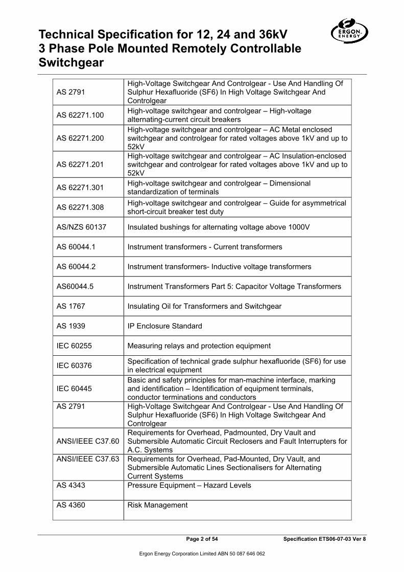
2.1 Applicable Standards All equipment shall be designed and manufactured in accordance with the relevant current Australian and overseas Standards including all amendments at the time of calling quotations, in particular:
Standard/Act Title
AS 1210 Pressure Vessels
AS 1243 Voltage Transformers For Measurement And Protection (where not yet superseded by AS 60044)
AS 2650 High Voltage A.C. Switchgear and Controlgear Common Requirements
Technical Specification for 12, 24 and 36kV 3 Phase Pole Mounted Remotely Controllable Switchgear
Page 2 of 54 Specification ETS06-07-03 Ver 8
Ergon Energy Corporation Limited ABN 50 087 646 062
AS 2791 High-Voltage Switchgear And Controlgear - Use And Handling Of Sulphur Hexafluoride (SF6) In High Voltage Switchgear And Controlgear
AS 62271.100 High-voltage switchgear and controlgear – High-voltage alternating-current circuit breakers
AS 62271.200 High-voltage switchgear and controlgear – AC Metal enclosed switchgear and controlgear for rated voltages above 1kV and up to 52kV
AS 62271.201 High-voltage switchgear and controlgear – AC Insulation-enclosed switchgear and controlgear for rated voltages above 1kV and up to 52kV
AS 62271.301 High-voltage switchgear and controlgear – Dimensional standardization of terminals
AS 62271.308 High-voltage switchgear and controlgear – Guide for asymmetrical short-circuit breaker test duty
AS/NZS 60137 Insulated bushings for alternating voltage above 1000V
AS 60044.1 Instrument transformers - Current transformers
AS 60044.2 Instrument transformers- Inductive voltage transformers
AS60044.5 Instrument Transformers Part 5: Capacitor Voltage Transformers
AS 1767 Insulating Oil for Transformers and Switchgear
AS 1939 IP Enclosure Standard
IEC 60255 Measuring relays and protection equipment
IEC 60376 Specification of technical grade sulphur hexafluoride (SF6) for use in electrical equipment
IEC 60445 Basic and safety principles for man-machine interface, marking and identification – Identification of equipment terminals, conductor terminations and conductors
AS 2791 High-Voltage Switchgear And Controlgear - Use And Handling Of Sulphur Hexafluoride (SF6) In High Voltage Switchgear And Controlgear
ANSI/IEEE C37.60 Requirements for Overhead, Padmounted, Dry Vault and Submersible Automatic Circuit Reclosers and Fault Interrupters for A.C. Systems
ANSI/IEEE C37.63 Requirements for Overhead, Pad-Mounted, Dry Vault, and Submersible Automatic Lines Sectionalisers for Alternating Current Systems
AS 4343 Pressure Equipment – Hazard Levels
AS 4360 Risk Management

Technical Specification for 12, 24 and 36kV 3 Phase Pole Mounted Remotely Controllable Switchgear
Page 3 of 54 Specification ETS06-07-03 Ver 8
Ergon Energy Corporation Limited ABN 50 087 646 062
AS 9001 Quality Management Systems - Requirements
Commonwealth of Australia Radio Communications Act 1992
Queensland Electrical Safety Act 2002
Queensland Workplace Health & Safety Act 1995
Queensland Workplace Health and Safety Act Risk Management Advisory Standard 2000 Queensland Workplace Health and Safety Plant Code of Practice 2005 Queensland Workplace Health & Safety Regulation 1997
Federal/State
DNP.org Document Library
If the equipment offered does not complying with Australian Standards, but complies with similar International Standards (eg. IEC), then detailed descriptions shall be given of the differences between the apparatus offered and the requirements of the specified Australian Standard. Note that the Purchaser will not accept equipment that does not comply in full with all relevant Queensland Safety Acts or Regulations. The following drawings form part of this specification:
3. Drawings
3.1 Drawings by the Purchaser 06-07-03/1 - 3 Phase Remotely Controllable ACR. High Voltage Bushings and HV Leads. 06-07-03/2 - 3 Phase Remotely Controllable ACR. General Arrangement 06-07-03/3 - 3 Phase Remotely Controllable Load Break Gas Switch. General Arrangement
4. Service Conditions
4.1 System Conditions The switchgear shall be suitable for use on non-effectively earthed and effectively earthed networks and under the system conditions as specified in Attachment 1:
Technical Specification for 12, 24 and 36kV 3 Phase Pole Mounted Remotely Controllable Switchgear
Page 4 of 54 Specification ETS06-07-03 Ver 8
Ergon Energy Corporation Limited ABN 50 087 646 062
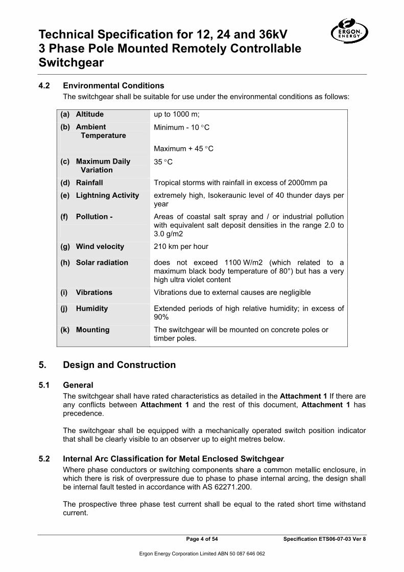
4.2 Environmental Conditions The switchgear shall be suitable for use under the environmental conditions as follows:
(a) Altitude up to 1000 m;
(b) Ambient Temperature
Minimum - 10 °C
Maximum + 45 °C
(c) Maximum Daily Variation
35 °C
(d) Rainfall Tropical storms with rainfall in excess of 2000mm pa
(e) Lightning Activity extremely high, Isokeraunic level of 40 thunder days per year
(f) Pollution -
Areas of coastal salt spray and / or industrial pollution with equivalent salt deposit densities in the range 2.0 to 3.0 g/m2
(g) Wind velocity 210 km per hour
(h) Solar radiation does not exceed 1100 W/m2 (which related to a maximum black body temperature of 80°) but has a very high ultra violet content
(i) Vibrations Vibrations due to external causes are negligible
(j) Humidity Extended periods of high relative humidity; in excess of 90%
(k) Mounting The switchgear will be mounted on concrete poles or timber poles.
5. Design and Construction
5.1 General The switchgear shall have rated characteristics as detailed in the Attachment 1 If there are any conflicts between Attachment 1 and the rest of this document, Attachment 1 has precedence. The switchgear shall be equipped with a mechanically operated switch position indicator that shall be clearly visible to an observer up to eight metres below.
5.2 Internal Arc Classification for Metal Enclosed Switchgear
Where phase conductors or switching components share a common metallic enclosure, in which there is risk of overpressure due to phase to phase internal arcing, the design shall be internal fault tested in accordance with AS 62271.200. The prospective three phase test current shall be equal to the rated short time withstand current.

Technical Specification for 12, 24 and 36kV 3 Phase Pole Mounted Remotely Controllable Switchgear
Page 5 of 54 Specification ETS06-07-03 Ver 8
Ergon Energy Corporation Limited ABN 50 087 646 062
The test duration for equipment shall be not less than 0.5s. (Note: 0.5s duration takes into account the consequences of possible upstream protection mal-function). Internal fault testing shall allow for Accessibility Type C (pole mount gear) as defined by AS 62271.200 Annex A2 and state the minimum admissible installation height with reference to the base of the switch, in accordance with that standard. The equipment shall satisfy an Internal Arc Classification C for the specified test current and duration. As the items 1 to 6 are also to be installed within substations, Tenderers shall state whether internal fault testing under the same conditions described above has been conducted for Accessibility Type A (restricted access installation). The equipment should preferably satisfy an Internal Arc Classification A for the specified test current and duration. Front, lateral and rear sides of the equipment should all be clearly stated. If the equipment offered for items 1 to 6 does not satisfy Internal Arc Classification A, the Tenderers shall state what restrictions should be placed on employing the equipment in a substation, where stand mounting is used. The safe location of personnel during an internal arc event is of particular importance.
5.3 Statutory Requirements for Unfired Pressure Vessels – SF6 The Supplier shall ensure that all equipment containing pressure vessels complies with AS 1210 to ensure the integrity of the pressure vessel design and fabrication. The Queensland Workplace Health & Safety Regulation 1997, requires specific pressure equipment designs to be registered. Schedule 4 requires registration for pressure equipment with hazard levels A, B, C or D as determined from AS 4343. Tenderers shall indicate whether the offered equipment requires design registration under the WH&SR1997 and either provide evidence of such registration or demonstrate with reference to the Regulation and relevant standard why registration is not required. The Queensland Workplace Health & Safety Regulation 1997 classifies certain pressure equipment as “Registrable Plant”. Under Schedule 3, all installed pressure equipment categorised as hazard levels A, B or C under AS 4343 require registration unless one of three exemption categories are met. Tenderers shall clearly state whether the offered equipment is “Registrable Plant” under the QH&SR1997 or demonstrate with reference to the Regulation and relevant standard why registration is not required. The successful Tenderer shall supply the Purchaser with Certificates of Registration under the WH&SR1997 for any pressure vessels requiring such registration within 30 days of award of contract. The Tenderer’s attention is drawn to the Division of Workplace Health & Safety contact details: http://www.dir.qld.gov.au/workplace/training/registrations/plant/type/index.htm The Technology Unit, Division of Workplace Health & Safety Department of Industrial Relations PO Box 820, LUTWYCHE QLD 4030 Tel: + 61 7 3872 0584
Technical Specification for 12, 24 and 36kV 3 Phase Pole Mounted Remotely Controllable Switchgear
Page 6 of 54 Specification ETS06-07-03 Ver 8
Ergon Energy Corporation Limited ABN 50 087 646 062
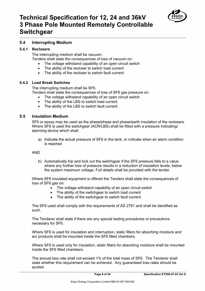
5.4 Interrupting Medium 5.4.1 Reclosers
The interrupting medium shall be vacuum. Tenders shall state the consequences of loss of vacuum on:
• The voltage withstand capability of an open circuit switch • The ability of the recloser to switch load current • The ability of the recloser to switch fault current.
5.4.2 Load Break Switches
The interrupting medium shall be SF6. Tenders shall state the consequences of loss of SF6 gas pressure on:
• The voltage withstand capability of an open circuit switch • The ability of the LBS to switch load current • The ability of the LBS to switch fault current.
5.5 Insulation Medium
SF6 or epoxy may be used as the phase/phase and phase/earth insulation of the reclosers. Where SF6 is used the switchgear (ACR/LBS) shall be fitted with a pressure indicating/ alarming device which shall:
a) Indicate the actual pressure of SF6 in the tank, or indicate when an alarm condition is reached
AND
b) Automatically trip and lock out the switchgear if the SF6 pressure falls to a value where any further loss of pressure results in a reduction of insulation levels, below the system maximum voltage. Full details shall be provided with the tender.
Where SF6 insulated equipment is offered the Tenders shall state the consequences of loss of SF6 gas on:
• The voltage withstand capability of an open circuit switch • The ability of the switchgear to switch load current • The ability of the switchgear to switch fault current.
The SF6 used shall comply with the requirements of AS 2791 and shall be identified as such. The Tenderer shall state if there are any special testing procedures or precautions necessary for SF6. Where SF6 is used for insulation and interruption, static filters for absorbing moisture and arc products shall be mounted inside the SF6 filled chambers. Where SF6 is used only for insulation, static filters for absorbing moisture shall be mounted inside the SF6 filled chambers. The annual loss rate shall not exceed 1% of the total mass of SF6. The Tenderer shall state whether this requirement can be achieved. Any guaranteed loss rates should be quoted.

Technical Specification for 12, 24 and 36kV 3 Phase Pole Mounted Remotely Controllable Switchgear
Page 7 of 54 Specification ETS06-07-03 Ver 8
Ergon Energy Corporation Limited ABN 50 087 646 062
If epoxy insulated switchgear is offered full details of the material used shall be provided with the Tender, including the service history and the number of units in service.
5.6 Switchgear Material
The tank shall be manufactured from hot dipped galvanized steel, 316 stainless steel or cast aluminium. Control cubicles shall be manufactured from 316 stainless steel. All support structures and associated bolts and nuts with these parts, shall be hot-dip galvanized. Suitable precautions shall be implemented to prevent corrosion due to the use of dissimilar materials and gases.
5.7 Mounting
The switchgear shall be suitable for single pole mounting, on concrete or timber poles. All units are to be supplied with a pole mounting bracket. It shall be possible to easily pass a body belt between the pole and the switchgear tank. The bracket and tank wall are to be of adequate strength to limit distortion, when mounted. Both the top and bottom bracket shall be suitable to carry the total weight of the tank on their own. Mounting brackETSshall provide for two slotted mounting holes at 360mm apart for mounting the recloser to the pole using M20 bolts in accordance with drawings 06-07-03/2 or 06-07-03/3 as applicable. Adequately rated lifting eyes shall be provided and they shall be designed to allow the completely assembled switchgear (surge arresters fitted) to be lifted without recourse to a sling spreader. The maximum angle of tilt when the assembly is lifted from the lifting eyes using a sling shall be 2.5 degrees from the plane of the mounting bracket. This also applies to units that incorporate the VT fitted on the switchgear mounting bracket or the switchgear. The switchgear shall be fitted with feet if necessary, to prevent overturning when placed on a level surface. The switchgear shall be fitted with an external M12 earth stud, complete with a nut, lock nut and serrated washer. A detailed drawing of the three phase switchgear mounting arrangements with surge arresters (and VT if applicable) fitted should be provided with the tender submission. The minimum phase to phase and phase-to-earth clearances (including clearances to the structure) shall be indicated on the drawing. CabinETSthat house equipment for protection and control shall be mounted independently of the tank.
Technical Specification for 12, 24 and 36kV 3 Phase Pole Mounted Remotely Controllable Switchgear
Page 8 of 54 Specification ETS06-07-03 Ver 8
Ergon Energy Corporation Limited ABN 50 087 646 062
5.8 Pressure Relief Tenderers shall describe any techniques employed for handling enclosure overpressure that could arise from internal arcs. Particular attention should be given to the direction and energy (mass/velocity) of discharge products. The switchgear shall incorporate a pressure relief/rupture mechanism, which is of a non fragmenting design, and designed to vent the pressure away from the operator in the event of an internal arc fault.
5.9 Control Cabinet The cabinet shall be designed for the service conditions specified, adequately ventilated and fitted with substantial door securing devices capable of being padlocked by a padlock with a shank of 8mm with the door in the closed position. It shall be possible to disconnect the cable at the tank while the ACR or the LBS is connected to the power system, without causing damage or mal-operation. Care shall be taken that CT's are not open circuited. A robust, multi-pin weatherproof connector shall be supplied. Preference will be given to products supplying connectors at both the tank and the control cabinet. The supplier shall ensure that the equipment housed in the control cabinet can withstand the heating effect of direct solar radiation without causing failure and/or mal-operation. Details shall be provided in the tender documentation. The control cabinet shall be mounted below the switchgear tank and shall be connected to the switchgear by a minimum seven meter long multi-core control cable. The multi-core cable shall be ultra violet stabilised and adequately screened against electrostatic and electromagnetic interference, which can cause malfunctioning of the protection or control equipment. This cable shall connect into both the ACR/LBS and the control cabinet by means of plug and socket arrangements. Entry of the control cable into the Control Cubicle shall be from the bottom. The control cabinet shall have adequate space provisions to mount the Purchasers communications equipment (mobile phone and modem or radio, plus power supplies if needed (ref Clause 5.19 & 5.22). A suitable shelf, or bracket or fixing mechanism should be supplied or easily fitted to allow the installation of the communications equipment. The space reserved and mounting arrangement should be suitable to mount either the Globalstar GS1620 satellite modem, or the LandCell CMD882seu 3G modem. The location within the cabinet for the communications equipment should include a method of cable management to suitably locate an RS232 cable or Ethernet cable from the communications equipment to the management interface on the switchgear. Where the Supplier is unable to provide accommodation for the Purchaser’s remote control equipment, the tender price shall be loaded with the cost for Ergon Energy to provide the required facilities. The cabinet shall make provision for bottom entry of at least two additional cables. The cabinet shall be pre-punched with at least one 21mm and one 32mm hole. The holes shall be suitably blanked off.

Technical Specification for 12, 24 and 36kV 3 Phase Pole Mounted Remotely Controllable Switchgear
Page 9 of 54 Specification ETS06-07-03 Ver 8
Ergon Energy Corporation Limited ABN 50 087 646 062
The cabinet shall be fitted with an external M12 earthing stud, with a nut, lock nut, and a serrated washer.
5.10 Earthing Provision shall be made to ensure the electrical continuity of all exposed metal. Earthing terminals shall be fitted to all such equipment. An earthing strap shall be provided between the lid and the tank of the switchgear. The control (umbilical) cable shall be adequately earthed to shield the control equipment against electrical interference. The cabinet should be suitably shielded so that an externally mounted 3G / GSM / CDMA antenna should not interfere with the normal operation of the equipment. Where minimum distance requirements for the mounting of an antenna apply, these should be stated.
5.11 Surge Arrester Brackets BrackETSshall be attached to the tank (not on the lid), one adjacent to each HV bushing to enable mounting of surge arresters. The surge arrester brackETSshall be used as the connection point for the arrester earth. The brackETSshall have an unpainted corrosion resistant metal connecting zone which has the capability to conduct surge arrester current. A 14mm dia. hole shall be drilled in the bracket for the arrester mounting. The brackETSshall be constructed so as to accommodate the mounting of polymeric housed surge arresters. The arresters shall be mounted parallel to and in the same plain as the associated phase insulator. A minimum of 100mm clearance shall be provided between the sheds of the phase bushing and the arrester. Clearances between the ACR/LBS structure/metalwork and surge arresters shall be as such that phase to ground clearances are achieved.
5.12 Markings and Nameplates The switchgear bushing terminals shall be clearly marked on the normal line side and the normal load side in accordance with clause 7.2 of IEC 60445. These markings will be of a quality to remain viewable for the products working lifetime. A Name plate shall be provided on the switchgear and the associated controller using a non ferrous material or stainless steel, with the following information engraved, indelibly stamped or etched:
• Manufacturers Name • Manufacturers type or identification no • Serial No and date of manufacture • Rated maximum voltage • Rated Continuous current • Rated symmetrical interrupting current • Rated impulse withstand voltage • Purchaser’s Item Identification Number • Purchaser’s Structured Plant Number (this will be nominated in the purchase orders
to the successful Tenderer and will be an 8 digit number prefixed by 2 alphas).

Technical Specification for 12, 24 and 36kV 3 Phase Pole Mounted Remotely Controllable Switchgear
Page 10 of 54 Specification ETS06-07-03 Ver 8
Ergon Energy Corporation Limited ABN 50 087 646 062
The name plate shall be mounted clear of live parts in a position likely to be readable while the switchgear is in service without compromising safety of the operator.
5.13 Operating Mechanism The switchgear may use either the nominal HV supply from the source side bushings or a low voltage system supplied from a battery or voltage transformer to operate a closing mechanism. Tripping energy shall be supplied from a spring mechanism automatically tensioned when the switch unit is closed. Internal batteries used for the above purpose shall not have any dependence on the load current to maintain their state of charge. The ACR shall incorporate provision for an operator to manually open the recloser using a standard operating stick in the event that the electrical control system has failed. The LBS shall be provided with a manual operating lever suitable for open and close operations. The operating lever provided shall be suitable for operations using a standard hook stick. Clear and unambiguous indication shall be provided to an operator standing on the ground as to the status of the recloser main contacts. This shall be by an indicator mechanically linked to the switching mechanism and shall be clearly visible to an observer eight metres below the switchgear. Symbols and colours for the indicators shall be a Red “1” or "ON" for ON and Green “0” or "OFF" for OFF. The colours shall remain vivid for the products working life. Painted symbols are unacceptable.
5.14 Maintenance Inspection and Test The switchgear mechanism and vacuum interrupters shall be designed to be maintenance free. The control system shall incorporate a system which provides an approximate indication of the life remaining in the vacuum interrupters. This system shall use the measured value of interrupted current and a formulae approved by the vacuum interrupter manufacturer to calculate the remaining life of the interrupters. The switchgear with SF6 interrupters shall be provided with facilities for monitoring of contact erosion in a similar manner. Facilities shall be available to allow secondary injection into the protection relay to prove the relay functions. This shall be able to be completed with the switchgear in service and live.
5.15 High Voltage Bushings and HV Leads Bushings shall be manufactured and tested in accordance with AS60137. The HV bushings shall be of high quality glazed porcelain, or cyclo aliphatic epoxy resin bushings and silicon bushing boots having a protected creepage length of not less than that specified in Attachment 1. A dimensioned drawing of the bushing (and boot if applicable) shall be supplied with the tender. If the switchgear offered is provided with cyclo aliphatic bushings and silicon rubber bushing boots, each bushing terminal shall be provided with a fully insulated water blocked HV lead in accordance with the drawing 06-07-03/1. The leads shall be continuously rated for 400A and have a minimum insulation withstand level of 125kVp. Terminal compression

Technical Specification for 12, 24 and 36kV 3 Phase Pole Mounted Remotely Controllable Switchgear
Page 11 of 54 Specification ETS06-07-03 Ver 8
Ergon Energy Corporation Limited ABN 50 087 646 062
lugs shall be fitted to the free ends of the HV leads to allow for connections to the source/load side jumpers and the surge arresters. The palm of the lug shall be suitable for connection to aluminum or copper based components using an M12 stainless steel fastening, and the barrel shall be compatible with the cable core material. The interface between the lug and the cable insulation shall be fitted with a mastic lined heat shrinkable sleeve or similar to prevent the ingress of moisture into the cable. If the switchgear offered is provided with porcelain or cyclo aliphatic bushings having the protected creepage length and impulse withstand level complying with Attachment 1 (without the use of additional bushing boots), the bushing terminals shall be provided with terminal palms / clamps suitable for attaching the source/load side jumpers (95 mm2 insulated copper cable), and surge arrester leads (16 mm2 insulated copper cable). The bushing terminals shall be provided with insulating terminal covers designed to protect the switchgear from wildlife whilst still permitting the connection HV jumpers and surge arrestor leads.
5.16 Surge Arresters The switchgear shall be supplied fitted with HV surge arresters (including wildlife guards and other accessories) complying with the requirements of Ergon Technical Specification ETS09-01-01(3), both on the source side and the load side, in accordance with the following table.
Contract
Item Number
Recloser Type Surge Arrester Type to ETS09-
01-01(3)
1 Automatic Circuit Recloser (ACR) 11 kV 3 phase complete with auxiliary voltage transformer, lightning arresters, insulated cable droppers, arrester and VT wiring
Item 2
2 Automatic Circuit Recloser (ACR) 22 kV 3 phase complete with auxiliary voltage transformer, lightning arresters, insulated cable droppers, arrester and VT wiring
Item 6
3 Automatic Circuit Recloser (ACR) 33 kV 3 phase complete with auxiliary voltage transformer, lightning arresters, insulated cable droppers, arrester and VT wiring
Item 9
4 Load Break Switch (LBS) 11 kV 3 phase complete with auxiliary voltage transformer, lightning arresters, insulated cable droppers, arrester and VT wiring
Item 2
5 Load Break Switch (LBS) 22 kV 3 phase complete with auxiliary voltage transformer, lightning arresters, insulated cable droppers, arrester and VT wiring
Item 6
6 Load Break Switch (LBS) 33 kV 3 phase complete with auxiliary voltage transformer, lightning arresters, insulated cable droppers, arrester and VT wiring
Item 9
Full details of the surge arresters offered, including the completed Attachment 2 of specification ETS09-01-01(3) shall be supplied with the tender documentation.
5.17 Current Transformers Suitable current transformers shall be provided on all three phases of the ACR/LBS to provide the protection functions as required by this specification.
Technical Specification for 12, 24 and 36kV 3 Phase Pole Mounted Remotely Controllable Switchgear
Page 12 of 54 Specification ETS06-07-03 Ver 8
Ergon Energy Corporation Limited ABN 50 087 646 062
They shall be of a class and ratio adequate to ensure they do not saturate under fault conditions up to the full rated interrupting current. Current transformers shall be thermally rated to switchgear current rating regardless of the ratio selected. All current transformers shall be in accordance with AS 60044.1 and shall preferably be of the bushing type. Tenderers offering sensors other than current transformers for interfacing with the switch controller shall provide details of the standards to which the sensors are designed and tested.
5.18 Voltage Transformers
Line voltage shall be monitored on all six LBS HV terminals to allow remote monitoring of supply availability from either direction. Line voltage shall be monitored on at least the three ACR supply HV terminals and preferably all six terminals. Tenderers shall state whether the metering or protection voltage transformers are capacitively coupled, inductive or a combined instrument transformer complying with one or more of the standards; AS 60044.2, AS 60044.3, AS 60044.5 or AS 1243. Tenderers shall quote accuracy for the metering or protection VTs to one of the standards listed above.
5.19 Auxiliary Supply Auxiliary supply for the control/operating system shall normally be from an internal sealed battery fitted with a charging system. The charger shall operate from an auxiliary HV voltage transformer, incorporated into the installation. The voltage transformer shall be designed, manufactured and tested in accordance with AS 60044.2. The Purchaser prefers the voltage transformer to be mounted on the ACR mounting bracket or tank. A name plate shall be provided on the auxiliary VT with the following information:
• Manufacturer's name • Serial number and date of manufacture • Rated impulse withstand level • Primary and secondary voltages • Rated current
The auxiliary supply system shall be protected against temporary over-voltages arising from disturbances in the HV distribution network. The temporary over-voltage withstand capability of the auxiliary supply system and the details of the measures incorporated for mitigating the effects of system disturbances on the protection, control and communication gear supplied by it shall be included in the tender documentation.

Technical Specification for 12, 24 and 36kV 3 Phase Pole Mounted Remotely Controllable Switchgear
Page 13 of 54 Specification ETS06-07-03 Ver 8
Ergon Energy Corporation Limited ABN 50 087 646 062
The primary winding of the transformer shall be connected to two phases of the 3 phase 3 wire system. Connection between one phase and earth is unacceptable. The secondary output voltage of the VT shall be 240V. A 2A HRC fuse or a circuit breaker shall be provided in the secondary terminal box of the VT to facilitate the isolation of the secondary wiring in the event of a fault. The battery system shall be capable of initiating correct operation of the recloser for not less than 36 hours after loss of ac auxiliary supply. The Tenderer shall indicate the number of normal reclose sequence operations possible within the 36 hour period. A 12V dc supply suitable for operation of communications equipment shall be provided within the enclosure. This may be from the same battery as the control supply, or a separate battery. It shall not be provided from the tripping/ closing battery. A Radio shut down feature shall be incorporated into the battery management to ensure the radio does not drain the battery if supply is lost over an extended period. Protection functions are to be available after the communications supply has been shut down. If the communication equipment uses the same battery supply as the protection and control, the tenderer shall provide details of its effect on the control operations described in clause 5.19.6 above. Required parameters for the Communications Supply are:
• A fuse or miniature circuit breaker shall be provided to protect and isolate the supply to the communications equipment.
• Voltage range 10.0V to 13.8V • Discharge rate : 0.5A average, 5A Maximum • Carry Over capacity in the absence of ac supply for 20 hrs at 0.5A discharge rate,
over and above the recloser equipment requirement. • Automatic reconnection of supply once the auxiliary supply is restored • The connection for the power supply should be situated in the area of the cabinet
reserved for the mounting of the communications equipment. • Ability to extend the supply, should there be a future requirement to power a second
communications device within the recloser Where the Supplier is unable to provide an auxiliary power supply to Ergon Energy’s remote control equipment, the tender price will be loaded with the cost for Ergon Energy to provide equivalent facilities. The Tenderer shall provide details of expected service life of batteries used. The battery system shall incorporate a battery test facility. The following features shall be regarded as typical of the 'test' / 'monitoring' facilities required.
a) An inbuilt instrument / instruments which can be a switch or push button configured
to display:
• Battery operating voltage. • Battery voltage under the effect of a dummy load. • Battery charge / discharge current.

Technical Specification for 12, 24 and 36kV 3 Phase Pole Mounted Remotely Controllable Switchgear
Page 14 of 54 Specification ETS06-07-03 Ver 8
Ergon Energy Corporation Limited ABN 50 087 646 062
The dummy load shall be built into the system and the manufacturer shall state in its manual.
• The normal steady state fully charged battery voltage. • Charging currents. • Recommended minimum battery voltage. • Maximum battery voltage reduction when the dummy load is applied.
b) An alarm shall be raised in the event of loss of the battery system.
Battery systems charged from current transformers are not acceptable.
5.20 Controls The control system shall allow for the following levels of control and indication for ACR and LBS:
• Operator Hook stick control & indication • Local Control Panel Control & indication • SCADA operation and indication • Engineering Access & Control
From all control positions the following general requirements shall apply for the ACR. SEF control ON/OFF is regularly required for switching purposes and its selection and control must be clear and definite without the possibility of inadvertently selecting other protections with the same control. EF protection is required to be capable of being turned OFF for placing the ACR in and out of service using single phase links. Its selection and control must be clear and definite without the possibility of inadvertently selecting other protections with the same control. Inhibiting EF and SEF must be allowed as an operator control, while turning off other protections that are enabled is not allowed. Operator Hook Stick Control - Refer Clause 5.13.3 Local Control Panel Control and Indication The ACR shall be equipped with the following local operation features through switches/push buttons operable by a gloved hand:
(a) Trip (with no reclosing) (b) Close (single shot) (c) Auto Reclose ON/OFF (d) Sensitive Earth Fault protection ON/OFF (e) Earth Fault protection ON/OFF (f) Live Line Working Clearance ON/OFF (g) Local / Remote Operation (h) View Trip Sequences and Status Information
SEF protection ON/OFF is to be presented for control selection as the sole control option, for example it is not to be presented as a combined EF/SEF selection. This is to ensure that EF is not inadvertently turned OFF when only SEF was intended.

Technical Specification for 12, 24 and 36kV 3 Phase Pole Mounted Remotely Controllable Switchgear
Page 15 of 54 Specification ETS06-07-03 Ver 8
Ergon Energy Corporation Limited ABN 50 087 646 062
EF protection ON/OFF control selection is not to be presented with any phase control options. A password protected menu selection shall inhibit the selection of turning OFF the phase and protection in general, excluding the above SEF ON/OFF selection. The following information shall be able to be viewed in full sunlight on a local Controller for the ACR
(a) Switch open status (b) Switch closed status (c) Remote control disable status (LOCAL) (d) Automatic sequence enable status (e) Sensitive earth fault protection disable status (f) Earth Fault protection disable status (g) Live Line Working Clearance Applied Status (h) Under Frequency disabled (i) Equipment integrity alarm(s) (as applicable to the type of equipment)
The LBS shall be equipped with the following local operation features through switches/push buttons operable by a gloved hand:
(a) Trip (with no reclosing) (b) Close (single shot) (c) Local / Remote Operation (d) View Trip Sequences and Status Information
The following information shall be able to be viewed in full sunlight on a local Controller for the LBS
(a) Switch open status (b) Switch closed status (c) Remote control disable status (LOCAL) (d) Automatic sequence enable status (e) Equipment integrity alarm(s) (as applicable to the type of equipment)
The following information shall be able to be viewed in full sunlight on a local display screen incorporated into the controller, or on a local PC connected to the controller an on-demand interrogation facility to indicate up to ten previous trips:
(a) Faulted phase/phases, (b) Protective device and sequence which initiated the trip and (c) Date and time of occurrence. (d) Interrupted current
5.21 SCADA Operation and Indication
The switchgear is required to be controlled and provide its indications using a remote PC or full SCADA system operating over a standard telephone line, an analogue radio, a digital phone, or a satellite phone and an associated modem where applicable. The switchgear shall be capable of operation using the following communications protocols:
• Serial DNP3.0, and • DNP3.0 over IP via an Ethernet port.
Technical Specification for 12, 24 and 36kV 3 Phase Pole Mounted Remotely Controllable Switchgear
Page 16 of 54 Specification ETS06-07-03 Ver 8
Ergon Energy Corporation Limited ABN 50 087 646 062
AS a minimum for the ACR the following controls and indications shall be provided to the Remote SCADA system using the selected protocol. Controls:
(a) Tripping and closing (b) Enable and disable automatic sequences (reclosing) (c) Enable and disable sensitive earth fault protection (d) Enable and disable Live line Working Clearance (e) Enable and disable Under Frequency protection (f) Change Protection Setting group (g) Reset fault flags and currents
Status:
(a) Switch open status (b) Switch closed status (c) Remote control disable status (LOCAL) (d) Automatic sequence enable status (e) Sensitive earth fault protection disable status (f) Live Line Working Clearance Applied Status (g) Under Frequency disabled status (h) Equipment integrity alarm(s) (as applicable to the type of equipment) (i) Over Current Trip (j) Earth Fault Trip (k) Sensitive Earth Fault Trip (l) Under Frequency Trip (m) Lockout (n) Auxiliary supply healthy (o) Active Protection setting group
Analogues:
(a) Current in each phase (b) Earth / Ground Current (c) Phase voltage on all phases (d) Frequency (e) Operations Counter (f) Battery Voltage (g) MW and MVAr (h) A Phase fault current (i) B Phase fault current (j) C Phase fault current (k) Earth fault current
AS a minimum for the LBS the following controls and indications shall be provided to the Remote SCADA system using the selected protocol. Controls:
(a) Tripping and closing (b) Change Protection Setting group (c) Reset fault flags and currents
Status: (a) Switch open status (b) Switch closed status

Technical Specification for 12, 24 and 36kV 3 Phase Pole Mounted Remotely Controllable Switchgear
Page 17 of 54 Specification ETS06-07-03 Ver 8
Ergon Energy Corporation Limited ABN 50 087 646 062
(c) Remote control disable status (LOCAL) (d) Equipment integrity alarm(s) (as applicable to the type of equipment) (e) Over Current Detection (f) Earth Fault Detection (g) Sensitive Earth Fault Detection (h) Auxiliary supply healthy (i) Active Protection setting group
Analogues:
(a) Current in each phase (b) Phase voltage on all phases (c) Operations Counter (d) Battery Voltage (e) MW and MVAr
When ACR/LBS is in LOCAL control it shall not be possible to reverse a local setting for the following by means of the REMOTE system:
• ACR/LBS Status – TRIP / CLOSE • Local control selection.
When ACR/LBS is in REMOTE control it shall be possible to reverse a local setting for all of the ACR/LBS features. The DNP3.0 interface shall allow for 4 data classes, three of which are for event data objects. Data objects shall be user configurable into each event class. Event classes shall be individually user configurable for both the number of events and time for which exception reporting shall occur. Where serial transmission is in use the RTU shall incorporate a collision avoidance and retry scheme to provide maximum probability of successful transmission of the report on a busy network. In this instance, serial transmission will be either by V23 over an external radio, or via a RS232 connection to an external modem. The RTU shall support the Hayes Command set on it’s serial modem interface. A DNP3.0 device profile shall be included in the Tender submission.
5.22 Engineering Access and Control
The switchgear is to be capable of being controlled and operated locally using Engineering Access software. Access should be available to the local management port of the switchgear from a PC using the supplier’s software. The software must support a TCP/IP over Ethernet connection via the local management port. The port should be FastEthernet RJ45 presentation. It shall support a standard TCP/IP stack and allow the unit to be provisioned with an IP address. Remote access is also required using one of a number of access technologies, including analogue radio, digital radio, DSL, Cellular Mobile or satellite. To support these technology options both serial and TCP/IP over Ethernet connectivity shall be provided. Additionally the Ethernet port shall be capable of being used for both Engineering Access and remote control simultaneously. Engineering Access shall have three password protected access levels as follows;
(a) Viewer access, allowing viewing of fundamental switchgear functional states, (b) Operator access, allowing the use of fundamental switchgear functions, and

Technical Specification for 12, 24 and 36kV 3 Phase Pole Mounted Remotely Controllable Switchgear
Page 18 of 54 Specification ETS06-07-03 Ver 8
Ergon Energy Corporation Limited ABN 50 087 646 062
(c) Full access, allowing full access to all recloser configuration settings and functions.
Preference shall be given to vendors with a related version of the Engineering Access software that is capable of server mode operation, i.e. with the ability to provide access for multiple users to multiple switchgear units via a TCP/IP network. Amongst its feature set, the software must be able to develop an audit trail of setting/programming changes for each switch gear unit. This software shall be downward compatible, i.e. a higher version of software shall provide access to all lower level firmware on the switchgear, to eliminate the need for multiple software versions from the same vendor to access different versions of firmware/hardware. To this end, the vendor shall also provide a ten year development timeline that shows any scheduled end of life support on the software, firmware and hardware. The vendor shall provide details of activities being undertaken in the IEC 61850 area regarding the communications protocols of its switch gear.
For the ACR the following features shall be able to be controlled/monitored using this facility:
(a) Tripping and closing (b) Enable and disable automatic sequences (reclosing) (c) Enable and disable sensitive earth fault protection (d) Enable and disable Live line Working Clearance (e) Toggle between the main and alternative trip settings. (f) Under Frequency Protection (g) Read and display metering data including a summary page. (h) Reset the stored maximum demand. (i) Read the operations counter. (j) Read the event recorder and display at least the last 50 events in time
sequence complete with feeder currents at the time of the event. (k) Display a summary page which shows the number of fault trips since it was
last reset. (l) Examination of recloser/control system malfunction alarms. (m) Read all recloser settings. (n) Write all recloser settings.
For the LBS the following features shall be able to be controlled/monitored using this facility:
(a) Tripping and closing (b) Toggle between the main and alternative trip settings. (c) Read and display metering data including a summary page. (d) Reset the stored maximum demand. (e) Read the operations counter. (f) Read the event recorder and display at least the last 50 events in time
sequence complete with feeder currents at the time of the event. (g) Display a summary page which shows the number of fault trips since it was
last reset. (h) Examination of LBS/control system malfunction alarms. (i) Read all LBS (sectionaliser) settings. (j) Write all LBS (sectionaliser) settings.

Technical Specification for 12, 24 and 36kV 3 Phase Pole Mounted Remotely Controllable Switchgear
Page 19 of 54 Specification ETS06-07-03 Ver 8
Ergon Energy Corporation Limited ABN 50 087 646 062
5.23 Sequence of Operation In the event of a fault on the section of the line controlled by a Recloser, the Recloser shall automatically open, and after a minimum dead time it shall reclose and remain closed should the line be no longer faulty. (Auto Reclose set to ON). Should the fault persist, the Recloser shall again disconnect the section of line being controlled. The Recloser shall be capable of not less than three automatic reclose operations at rated short circuit current should the fault persist and then lock out in the open position until reset by hand or remote control. If the fault is of a transient nature the equipment shall remain closed, and the operating mechanism shall automatically reset. The number of operations to lockout shall be adjustable in any combination of instantaneous and time-delayed trips up to a maximum of four with a minimum dead time of 0.5 seconds for the first operation/ The LBS shall be able to be used as a sectionaliser in conjunction with an upstream ACR. When subjected to an overcurrent followed by a current below its dead line threshold level, the sectionaliser shall count one recloser operation (trip). Subsequent recloser operations shall be counted by the sectionaliser and when a predetermined count is reached the sectionaliser shall isolate the faulty circuit while the recloser is in the open position. The recloser can then restore power to the healthy part of the system. If the fault is of temporary nature and is cleared before the sectionaliser count reaches the predetermined number, the sectionaliser shall remain closed and shall reset to its pre-fault condition after the reset time is expired. The LBS will also be used as an “open point” between two feeders supplied from different substations and consequently the supply voltage and the phase angle on either side of the switch may vary. The Tenderer shall state the maximum variation in voltage and phase angle between the two sources under which the switch offered will be able to perform the closing/opening operations safely. Reports of testing carried out to establish these values shall be enclosed with the tender submission.
5.24 Protection
All switchgear shall be fitted with three separate current transformers, one on each phase for over-current and earth fault protection. The switchgear shall be supplied complete with an integrated microprocessor based control and protection system incorporating all the features stated in the following sub sections of this clause. The equipment shall be capable of stand alone operation. Upon restoration of normal power supplies after prolonged failure all equipment will be restored to full operational capability. All user settings and parameters will be retained in nonvolatile memory. Over-current & Earth Fault Protection (OC & EF) ACR The protection system shall provide over-current protection on all 3 phases plus earth of the circuit supplied by the recloser. Each of up to four shots in a reclose sequence shall have

Technical Specification for 12, 24 and 36kV 3 Phase Pole Mounted Remotely Controllable Switchgear
Page 20 of 54 Specification ETS06-07-03 Ver 8
Ergon Energy Corporation Limited ABN 50 087 646 062
independent curve, time (multiplier) and curve modifier settings and a common over-current and earth fault pick up current setting. The over-current protection system shall be independent of all other protection systems specified herein in that none of its settings shall be restricted by, or conditional upon the settings of other types of protection. The over-current trip pick up value shall be programmable between 10 and 1000 amps in steps of not more than 1A. The earth fault protection system shall be independent of all other protection systems specified herein in that none of its settings shall be restricted by, or conditional upon the settings of other types of protection. The earth fault trip pick up value shall be programmable between 10 and 1000 amps in not more than 1A steps. The over-current and earth fault protection shall provide at least the following facilities on each of the four trips.
(a) Choice of not less than the following Time/Current Characteristics: • Definite Time • IEC60255 Standard Inverse • IEC60255 Very Inverse • IEC60255 Extremely Inverse
(b) Time multiplier variable between 0.05 and 2.0 in steps not greater than 0.01 (c) Definite Time variable between 0.05 to 10s in steps not greater than 0.01s (d) Control system operational accuracy not greater than +/- 10% or 20 ms
whichever is the greater. (e) Provisions to program a minimum operate time into the time / current
characteristic. This shall be variable between 0 and 2 seconds in steps not greater than 0.01s.
(f) Provision to program an additional operate time curve modifier into the time / current characteristic. This shall be variable between 0 and 2 seconds in steps not greater than 0.01s.
(g) Hiset over current trip setting which can be set in multiples from 1 to 30 times (in steps of 0.1) the normal pick up level setting. A definite time delay to be able to be applied to the Hiset, setting values of 0.05 to 2.0 seconds in steps not greater than 0.05 seconds.
(h) The trip sequence shall be able to be programmed to have one (1) to four (4) trips to lock-out.
Over-current & Earth Fault Detection (OC & EF) LBS The protection system shall provide over-current detection on all 3 phases plus earth of the circuit supplied by the LBS. The over-current detection system shall be independent of all other protection systems specified herein in that none of its settings shall be restricted by, or conditional upon the settings of other types of protection. The over-current detection value shall be programmable between 10 and 1000 amps in steps of not more than 1A.

Technical Specification for 12, 24 and 36kV 3 Phase Pole Mounted Remotely Controllable Switchgear
Page 21 of 54 Specification ETS06-07-03 Ver 8
Ergon Energy Corporation Limited ABN 50 087 646 062
The earth fault detection shall be independent of all other protection systems specified herein in that none of its settings shall be restricted by, or conditional upon the settings of other types of protection. The earth fault detection value shall be programmable between 10 and 1000 amps in not more than 1A steps. The over-current and earth fault protection shall provide at least the following facilities on each of the four trips.
(a) Detection Time variable between 0.05 and 100.0 seconds in steps not greater than 0.01.
(b) Control system operational accuracy not greater than +/- 10% or 20 ms whichever is the greater.
(c) The trip sequence shall be able to be programmed to have one (1) to four (4) counts of supply interruptions to trip.
(d) Sequence reset time shall be in the range of 1 to 180 seconds in steps no greater than 1 second.
Sensitive Earth Fault Protection (SEF) The ACR protection system shall provide sensitive earth fault protection on the circuit supplied by the recloser. The sensitive earth fault setting shall be applicable to all shots in the sequence; alternatively four settings shall be available to specify the SEF setting at each shot. The SEF protection shall be independent of all other protection systems specified herein in that none of its settings shall be restricted by, or conditional upon the settings of other types of protection. The trip pick up value shall be programmable between 1 and 20 amps in not more than 1A steps. The SEF shall have definite time operation with the time to trip adjustable between 1 and 30 seconds in steps not greater than 0.1 second. The number of trips to lock-out shall be programmable between one (1) and four (4), independent of other protection settings. The control system operational accuracy shall be not greater than +/- 10%. The SEF protection shall be able to be programmed either 'in' or 'out' of service. ACR Directional Over-Current and Earth Fault Protection The protection system shall provide for full directional over-current and full directional earth fault protection. The voltage signals for directional protection should ideally come from an integrated voltage sensing source, rather than an external VT. The directional control shall be selectable and the relay shall maintain directionality down to at least 1% primary voltage.

Technical Specification for 12, 24 and 36kV 3 Phase Pole Mounted Remotely Controllable Switchgear
Page 22 of 54 Specification ETS06-07-03 Ver 8
Ergon Energy Corporation Limited ABN 50 087 646 062
Directionality of the over-current and earth fault elements shall securely and positively identify faults either towards the protected equipment or away from the protected equipment as determined by the principle at the time of setting the relay. ACR Under/Over Voltage Protection The protection system shall provide for under voltage protection with auto reclose with following features:
(a) Trip setting from 0.5 to 0.8 pu voltage in steps of 0.01pu min. (b) Definite time delay 0 to 60.0 sec in steps of 0.1 sec (c) reset 1.0 sec to 10 seconds in steps of 0.5 seconds (d) Selection of any one phase U/V, or any two phases U/V to trip (e) Additional under voltage alarm only is desirable.
The protection system shall provide for over voltage protection with auto reclose with following features:
(a) Trip setting from 1.1 to 1.5 pu voltage in steps of 0.01pu min (b) Definite time delay 0 to 60.0 sec in steps of 0.1 sec (c) 1 sec to 10 seconds in steps of 0.1 seconds (d) Selection of any one phase O/V, or any two phases O/V to trip (e) Reclose single shot delayed after voltage comes into normal range (normal
reclaim time to apply) (f) Reclose time 1 to 300 seconds after good volts (g) Additional Voltage OK setting is desirable.
AC/LBS Voltage Monitoring Three phase voltage monitoring on both the supply and source side of the recloser. Loss of phase monitoring and optional loss of phase trip. ACR Circuit Breaker Fail Capability The supplier shall provide to the principle the ability to incorporate circuit breaker fail protection to allow the use of a supplied recloser in a substation location. ACR Reclose Times The reclose time between a trip operation and its subsequent close operation shall be able to be independently programmed for each trip cycle.
(a) The required time range is from one half (0.5) to one eighty (180) seconds in steps not greater than one half (0.1) second.
(b) The reset time between a successful recloser auto reclose operation and the time when the recloser’s full sequence is restored shall be able to be programmed in the range from 5 to 180 seconds in steps not greater than 1 second.
ACR Manual / Supervisory Close & Reset Time An auto reclose blocking feature shall be provided to prevent auto reclosing of the recloser if it trips for any reason within the reset time following a local manual or supervisory initiated close operation. This may be accomplished by means of the auto reclose reset timer or a separately programmable timer. The time setting range shall be the same as for the Auto Reclose Reset Time above.

Technical Specification for 12, 24 and 36kV 3 Phase Pole Mounted Remotely Controllable Switchgear
Page 23 of 54 Specification ETS06-07-03 Ver 8
Ergon Energy Corporation Limited ABN 50 087 646 062
All operator closes shall set the recloser protection curves to a Manual Close setting, or the CLP setting if selected. This curve shall remain active for the duration of the auto recloser reset timer. Cold Load Pick up (CLP) The ACR/ LBS shall incorporate a 'cold load' pick up feature to increase the probability of a successful close operation following a period of supply interruption to the feeder being supplied by the recloser. The CLP feature shall modify the OC curves. It shall not modify the EF or SEF curves. The CLP feature shall be able to be programmed IN or OUT of service. When Programmed IN service, this feature shall automatically apply to all supervisory initiated close operations and by operator selection, be available for local manually initiated close operations. The facility shall operate by one or a combination of the following methods:
• Specification of a separate curve for CLP • Specification of one of the specified OC curves for CLP • Specification of an increase in the minimum trip threshold multiple to be applied to a
specified curve. (Not an increase to the Pick Up value of the curve) Grading margins to up stream devices should not be compromised by the CLP scheme.
The ACR/LBS shall automatically detect loss of supply, and apply the CLP feature to the first shot curves, regardless of whether the recloser is Open or Closed. This is to prevent the recloser tripping due to a reclose by an upstream device. The application may use time based formula to determine the extent of the increase in tripping value. Alternative methods of providing this facility will be considered provided grading margins to upstream devices are not compromised. Manual Trip Any operator trip, Local or supervisory shall not initiate a reclose operation. ACR Live Line Working Clearance (LLWC) The ACR control system shall incorporate a LLWC feature that when set ON blocks all close commands, both operator and automatic protection (reclose) initiated. The selected state of the LLWC shall be maintained through out loss of supply of the auxiliary supplies, HV supplies, and throughout fault transients. The LLWC feature shall be capable of being placed and removed both locally and remotely, provided the appropriate location of control has been locally selected. ACR Trip Circuit Supervision The supplier shall provide to the principle the ability to incorporate trip circuit supervision protection to indicate for abnormal conditions in the trip circuit. ACR Sequence Coordination Sequence coordination facilities shall be provided to allow the recloser to coordinate with downstream reclosers.

Technical Specification for 12, 24 and 36kV 3 Phase Pole Mounted Remotely Controllable Switchgear
Page 24 of 54 Specification ETS06-07-03 Ver 8
Ergon Energy Corporation Limited ABN 50 087 646 062
The system shall operate by the recloser changing to its next operating characteristic if it measures a current pulse above its trip setting which is interrupted by another device before the set time elapses for this recloser to operate. The sequence coordination shall reset in the same manner as a normal successful auto reclose operation. The facility shall be able to be programmed either 'in' or 'out' of service. Stored Main and Alternative Settings The switchgear shall be capable of storing both main and alternative sETSof protection trip level settings, curves and modifiers. These shall allow the switchgear to be reset to an alternative set of settings to allow for changes to the power system configuration during switching operations etc. Operations Counter The control system shall incorporate an operations counter which cumulatively records the number trip operations. Local ACR/LBS Programming & Setting Entry Keyboard facilities shall be provided to program the switchgear and its control system. These shall also provide a means for local interrogation of the switchgear, its settings, metering and event data. The keyboard data entry system shall be arranged to have at least two levels of use. The first or lower level shall allow an operator to 'read' all stored values but not alter any settings etc. The second or higher level shall be password protected and shall allow a suitably empowered person to both 'read' data and 'write' new settings etc to the control system memory. Facilities shall also be provided to interrogate and program the complete control system using a 'laptop' computer and purpose written software. The software shall be provided with the recloser and its use by the purchaser shall not be restricted in any way other than the purchaser agreeing not to pass it on to a third party.
5.25 Metering The ACR/LBS shall have integral metering facilities which shall be configurable and record at least the following data:
• Present instantaneous rms current in each phase and earth. • Voltage in each phase • Watts and VArs • Time period selectable integrated maximum demand rms current in each phase and
earth. • The recloser shall also store the integrated maximum demand current, Watts, Vars
and Volts for at least the previous 1 week period. • The maximum demand value shall be capable of being reset from the operator
keyboard.
5.26 Event Recorder The ACR/LBS shall have an integral event recorder which shall store at least the last 50 events in time sequence. It shall include a real time clock and all events shall be time tagged with the date and time the event took place. Time resolution shall be to the nearest hundredth of a second. All events shall also list the measured values of the currents in each phase and earth at the time of the event.

Technical Specification for 12, 24 and 36kV 3 Phase Pole Mounted Remotely Controllable Switchgear
Page 25 of 54 Specification ETS06-07-03 Ver 8
Ergon Energy Corporation Limited ABN 50 087 646 062
At least the following shall be classed as events and recorded accordingly:
• Overcurrent & earth fault initiated trips. • SEF protection initiated trips. • Sequence coordination operations. • Local close and trip operations. • Supervisory close and trip operations. • Recloser resetting after operation. • Loss and restoration of ac auxiliary supply. • Unit Malfunction alarms, low gas and Battery Volts low alarms.
5.27 Desirable Optional Features
The following features are considered as desirable and would be considered an advantage to the Tenderer if available. Desirable to have an optional loop control scheme to allow automatic transfer of the supply feed and sectionalisation of the network upon one section becoming faulted. This scheme would preferably operate on local signals and timers, rather than a master controller relying on communications. Any such scheme must take into consideration that any reclosing or re-energisation of a potentially faulted feeder must occur within 15 seconds of being last energised. Provision of an inrush restraint scheme to lift the threshold of operation for OC and EF curves for a definite time following energisation, either from the recloser itself, or a upstream device. Provision of an optional isolated 4 wire multi-drop interface to allow communication to multiple reclosers in a substation environment. Maintenance of switchgear wear information continuously applicable regardless of swapping of the control and protection cubicle. Over-current and Earth Fault protection would be desirable to have optional separate trip sequences. Provisions supplied to allow for the integration of external protection to initiate a trip of the device.
5.28 Software
The software shall become the property of Ergon Energy and there shall be no restrictions on the number of PCs it is installed on. Where required, Ergon Energy will take all reasonable precautions to ensure the software shall not be passed onto third parties. The tender price for the recloser units shall include all software necessary for the proper functioning of the equipment as described in this specification. Any software upgrades carried out during the course of the contract shall be supplied to the purchaser free of charge. The software shall be capable of running on Microsoft Windows XP SP2 operating system. The Tenderer shall state the plans and timetable to migrate this software to Microsoft Windows 7 operating system.

Technical Specification for 12, 24 and 36kV 3 Phase Pole Mounted Remotely Controllable Switchgear
Page 26 of 54 Specification ETS06-07-03 Ver 8
Ergon Energy Corporation Limited ABN 50 087 646 062
6. Performance and Testing
6.1 Type Tests Copies of certificates of all type tests shall be submitted with the quotation. These tests shall be in accordance with the Design Tests set out in Section 6 of ANSI/IEEE C37.60 and Section 6 of ANSI/IEEE C37.63 as applicable. In addition the electronic protection/control unit shall have been subject to the relevant impulse, and high frequency noise immunity tests specified in IEC 60255 or equivalent national standards. Also, the ACR/LBS with their control/protection equipment as a composite unit (including earths) shall have been tested for rated impulse withstand level and for immunity against the effects of EMI and RFI. Copies of the type test certificates for the auxiliary voltage transformer carried out in accordance with AS60044.2 Clause 8 shall be submitted with the offer.
6.2 Routine Tests Routine tests shall be carried out on all equipment supplied and shall be according to the Production Test set out in Section 7 of ANSI/IEEE C37.60 and Section 7 of ANSI/IEEE C37.63 as applicable. Partial discharge tests shall be carried out as a routine test on all ACR/LBS with solid dielectric insulation in accordance with Annex B of AS 62271.200. One copy of the test results shall accompany each unit of switchgear delivered. A second copy of the test certificates shall be forwarded to the Purchaser via electronic mail to: [email protected] All test certificates shall include the manufacturer’s serial number, the Purchaser’s structured plant number, the order number, contract/item number and specification number. The test certificates shall also be accompanied with a completed Attachment 5 –Nameplate Details as applicable. Routine tests on the auxiliary VT’s shall be conducted in accordance with AS60044.2, clause 9. Certificates of Compliance covering the items supplied shall be provided with each delivery. Routine test certificates for the VT’s shall also be forwarded to the Purchaser via electronic mail to: [email protected] The Contractor shall give the Purchaser reasonable notice of when the routine tests are to be carried out. The Purchaser reserves the right to appoint representatives to witness the tests as well as conduct design reviews, and periodic inspection of the reclosers during manufacture.
6.3 Additional Tests 6.3.1 Millivolt Drop Test
Millivolt Drop Test or equivalent resistance measurement to the manufacturer's standards shall be taken across the main contacts, recloser terminals, and the primary terminals of every self-contained portion of the switch unit. Results obtained for the type tested unit shall serve as a datum for the purpose of comparison. These tests shall be in accordance with manufacturer’s standards, details of which shall be supplied with the quotation.

Technical Specification for 12, 24 and 36kV 3 Phase Pole Mounted Remotely Controllable Switchgear
Page 27 of 54 Specification ETS06-07-03 Ver 8
Ergon Energy Corporation Limited ABN 50 087 646 062
6.4 Tests on Delivery Subsequent to delivery and before installation, the equipment will be tested by the Purchaser to prove that it conforms to the requirements of this specification. These tests may include the tests carried out at the maker's works and all such tests as may be considered necessary by the Purchaser to prove that the equipment as delivered meETSwith the requirements of this specification. Any equipment showing evidence of failure to comply with the requirements of this specification shall be liable to rejection.
7. Risk Assessment
7.1 Compliance The Tenderer warrants (without limiting any other warranties or conditions implied by law) that all Goods have been produced, sold and delivered to the Principal in compliance with all applicable laws (including all workplace health and safety and electrical safety legislation, codes of conduct and the Principal’s Workplace Health & Safety and Electrical Safety Conditions).
7.2 Formal Risk Assessment Offered items shall be subjected to a formal risk assessment prior to acceptance. It is preferred that the supplier performs the risk assessment themselves and provides the resultant documentation with their offer. Where risk assessment documentation is not provided with the offers, or does not meet the required standard, such offers shall have their price loaded with the estimated costs associated with the Purchaser conducting the assessments. Any documented risk assessment which accompanies the offer must meet the requirements of AS/NZS 4360:1995 Risk Management as a minimum standard. It is preferred that the risk assessment methodology uses an energy model to identify hazards.
7.3 Hazards The risk assessment/s must identify hazards to the corporation personnel, public and property associated with:
• The installation of the equipment • The operation and maintenance of the equipment during life expectancy • Dismantling/disposal of equipment at end of life • The “Risk Assessment” schedule included with this specification is to be completed
by the Supplier. Note the schedule contains a generic set of questions designed to cover all the purchaser’s plant and materials and the supplier is only required to complete those items applicable to the product offered.
8. Quality Assurance
8.1 Purchasers Policy It is the Purchaser’s policy to procure goods, equipment and services from sources that demonstrate the ability to supply quality products.

Technical Specification for 12, 24 and 36kV 3 Phase Pole Mounted Remotely Controllable Switchgear
Page 28 of 54 Specification ETS06-07-03 Ver 8
Ergon Energy Corporation Limited ABN 50 087 646 062
8.2 Documentary Evidence Tenderers are required to submit evidence that the design and manufacture of the cable is in accordance with AS/NZS ISO 9001 and shall include the Capability Statement associated with the Quality System Certification.
If the Tenderer is a non-manufacturing supplier, the documentary evidence shall include the quality system certifications of both the supplier and the manufacturer.
9. Samples
9.1 Production Samples Tenderers shall state if they are prepared to make a sample unit as offered against this specification available to the purchaser for testing and evaluation. All costs for delivery and return of this sample unit shall be the responsibility of the tenderer.
10. Packaging and Marking
10.1 General Individual crates shall contain one ACR/LBS unit, control cubicle, auxiliary voltage transformer and all accessories. The equipment must be securely fastened to prevent movement during transport and handling. The crate must be constructed in a manner that allows the control cubicle door to be opened without removal from the crate. The crates must be sufficiently sturdy to allow for the removal of the equipment for testing purposes at the Purchasers testing facility, and the repacking of the equipment in the same package for transportation to the work sites. A copy of instruction manual for the equipment shall be provided in a weather proof bag inside each package.
10.2 Marking The following information shall be legibly and indelibly marked on TWO sides of the crate:
(a) Manufacturer’s name and catalogue number
(b) Rated Voltage and Current
(c) Purchase Order Number
(d) Purchasers Item Identification Number and the Structured Plant Number
(e) Description of contents and gross mass
(f) Handling or lifting instructions.

Technical Specification for 12, 24 and 36kV 3 Phase Pole Mounted Remotely Controllable Switchgear
Page 29 of 54 Specification ETS06-07-03 Ver 8
Ergon Energy Corporation Limited ABN 50 087 646 062
10.3 Quarantine Should any timber packaging be supplied from overseas manufactures, then it is mandatory that all conditions and inspections required by the Australian Quarantine Act be met and that all these costs be included in the offered price.
11. Service Performance
Potential first time Suppliers to the Purchaser shall state:
• The period of service achieved by the items offered within Australian service conditions;
• Australian electricity supply authorities who have a service history of the items offered;
• Contact names and phone numbers of relevant employees of those supply authorities who can verify the service performance claimed.
12. Reliability
12.1 Service Life The Purchaser requires Tenderers to offer equipment having a demonstrable track record of reliable performance. Preference will be given to plant which has been subjected to statistical reliability evaluation based on extensive field trails under the specified operating conditions. Tenderers offering untried equipment will be required to have had the plant, including in particular the electronic (solid state digital) control and protection and interface systems, subject to intensive reliability evaluation at the manufacturer's works on a simulated system. Such tests shall be over and above the normal type testing required by the specified IEC/AS/ANSI Standards.
12.2 Evidence in Support of Reliability Evidence of adequately proven reliability will be judged by The Purchaser on the basis of statistical data provided by Tenderers, e.g. Mean Time Between Failures preferably on a minimum of 1000 plant years data, and Failure Mode and Effect Analysis. Tenderers shall note in particular that The Purchaser’s distribution network is not to be treated as a reliability evaluation facility for untried or prematurely marketed products, for the purpose of this contract. When the Tenderer is unable to provide reliability data for 1000 plant years of service, an extended warranty for the control and communication components will be an acceptable alternative. The duration of the extended warrantee shall be five years from the date of commissioning.
13. Training
Training material in the form of drawings, instructions and/or audio visuals shall be provided for the items accepted under the offer. This material shall include but is not limited to the following topics:
Technical Specification for 12, 24 and 36kV 3 Phase Pole Mounted Remotely Controllable Switchgear
Page 30 of 54 Specification ETS06-07-03 Ver 8
Ergon Energy Corporation Limited ABN 50 087 646 062
• Handling • Storage • Application • Installation • Maintenance • Environmental performance • Electrical performance • Mechanical performance • Disposal
In addition training sessions shall be conducted for the benefit of the principles technical staff addressing no less than the following topics:
• Basic ACR/LBS features • Basic ACR/LBS operation • Field and remote control operation • Interrogation for access of event data, recloser status, fault and metering data • Fault finding • Application of protection and control settings
These training sessions shall be conducted in the purchaser's premises in Townsville, Rockhampton and Toowoomba.
14. Environmental Considerations
14.1 Environmental Soundness Suppliers are required to comment on the environmental soundness of the design and the materials used in the manufacture of the items offered. In particular, comments should address such issues as recyclability and disposal at end of service life and also disposal of packaging material. Suppliers offering equipment containing SF6 shall undertake to recover and recycle the SF6 gas remaining at the end of the service life of the equipment.
14.2 Queensland Government Occupational Health and Safety Act The Queensland Government Occupational Health and Safety Act require the Principle to assess the possible effects on health, safety and environment of chemical substances which are used in the manufacture of plant and materials.
14.3 Safety Data Sheet Tenderers are required to provide with their quotation documentation a Safety Data Sheet for every chemical substance used for electrical and thermal insulation, impregnation, and paint finish or for any other purpose.

Technical Specification for 12, 24 and 36kV 3 Phase Pole Mounted Remotely Controllable Switchgear
Page 31 of 54 Specification ETS06-07-03 Ver 8
Ergon Energy Corporation Limited ABN 50 087 646 062
15. Information to be Provided
15.1 Documentation to be supplied During the Course of the Contract 15.1.1 Drawings
Within four (4) weeks of the placing of the order, the successful tenderer shall supply three (3) copies of the following drawings.
(a) Schematic and wiring diagrams of component. (b) Layout drawings.
The Purchaser will approve only drawings or sections thereof which relate directly to integration with the Purchaser’s supplied equipment. The Purchaser will not approve schematic and wiring diagrams as this is considered the sole responsibility of the manufacturer. The supplier shall amend the drawings as directed and resubmit them for approval within fourteen (14) days. Tenderers wishing to provide drawings in electronic format should consult with the Purchaser to obtain details of acceptable standards.
15.1.2 Manuals Within eight (8) weeks of placing of the order, the successful tenderer shall supply fifteen (15) copies of a detailed operation and maintenance manual incorporating the following information.
(a) Schematic diagrams and component layouts of all printed circuit boards. (b) (b)A detailed list of all component parts including manufacturers part
numbers. (c) A detailed description of the circuit operation including block diagrams. (d) A comprehensive trouble-shooting guide to assist in fault-finding by qualified
personnel. (e) DNP3.0 profile documentation.
15.1.3 Test Certificates and Nameplate Details
Test certificates and completed Attachment 5 - Nameplate Details with each delivery as required in Clause 6
15.2 Documentation to be Supplied with the Offer The following documentation shall be included with the tender submission:
• Detailed scaled drawings / sketches, diagrams and photographs as necessary to fully describe the equipment being tendered
• Completed form Attachment 2 • Completed Attachment 3 - Risk Assessment • Supporting technical documentation requested in the Attachment 4
16. Warranty
The equipment shall be guaranteed against all defects, fair wear and tear accepted, for a period of not less than 36 months from date of delivery.
Technical Specification for 12, 24 and 36kV 3 Phase Pole Mounted Remotely Controllable Switchgear
Page 32 of 54 Specification ETS06-07-03 Ver 8
Ergon Energy Corporation Limited ABN 50 087 646 062
17. Spares
A table detailing spares and pricing is to be included. Include protection cards/boards, communications cards, cabinets, power supplies, VT’s, control cables, batteries, mounting structures etc. The tenderer shall provide relevant information on the availability and delivery of spare parts.
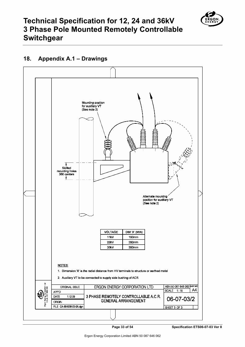
Technical Specification for 12, 24 and 36kV 3 Phase Pole Mounted Remotely Controllable Switchgear
Page 33 of 54 Specification ETS06-07-03 Ver 8
Ergon Energy Corporation Limited ABN 50 087 646 062
18. Appendix A.1 – Drawings

Technical Specification for 12, 24 and 36kV 3 Phase Pole Mounted Remotely Controllable Switchgear
Page 34 of 54 Specification ETS06-07-03 Ver 8
Ergon Energy Corporation Limited ABN 50 087 646 062
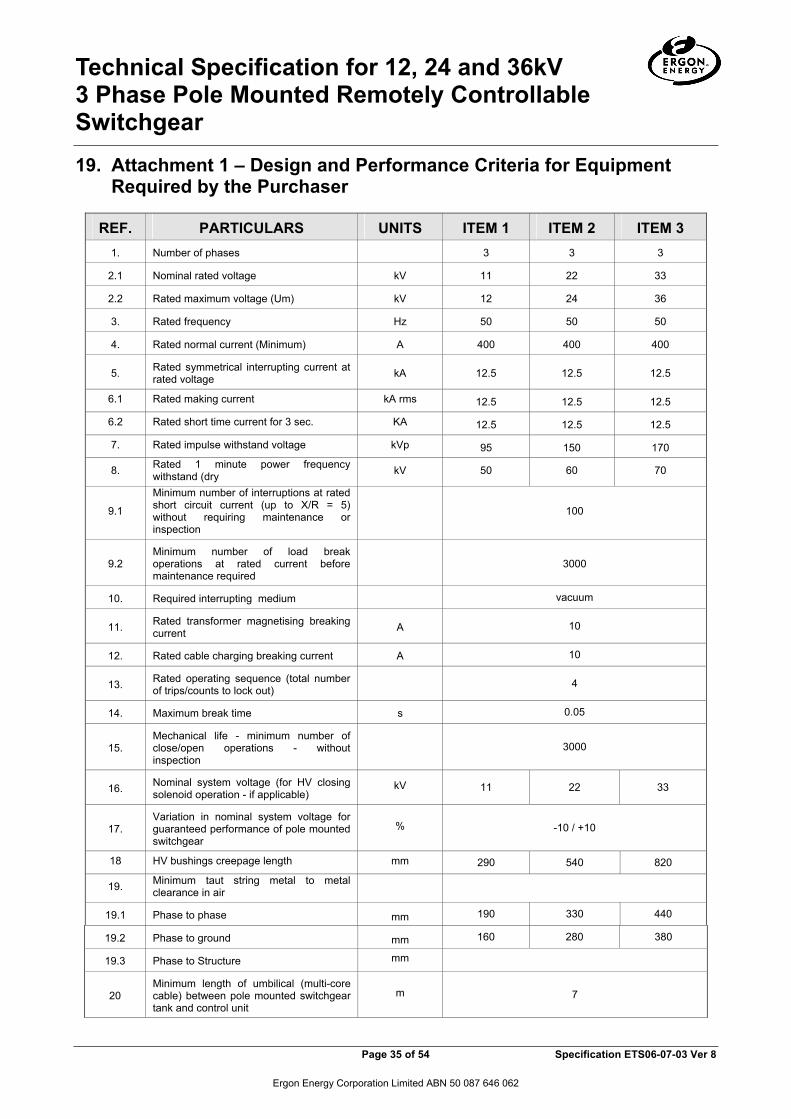
Technical Specification for 12, 24 and 36kV 3 Phase Pole Mounted Remotely Controllable Switchgear
Page 35 of 54 Specification ETS06-07-03 Ver 8
Ergon Energy Corporation Limited ABN 50 087 646 062
19. Attachment 1 – Design and Performance Criteria for Equipment Required by the Purchaser
REF. PARTICULARS UNITS ITEM 1 ITEM 2 ITEM 3 1. Number of phases 3 3 3
2.1 Nominal rated voltage kV 11 22 33
2.2 Rated maximum voltage (Um) kV 12 24 36
3. Rated frequency Hz 50 50 50
4. Rated normal current (Minimum) A 400 400 400
5. Rated symmetrical interrupting current at rated voltage kA 12.5 12.5 12.5
6.1 Rated making current kA rms 12.5 12.5 12.5
6.2 Rated short time current for 3 sec. KA 12.5 12.5 12.5
7. Rated impulse withstand voltage kVp 95 150 170
8. Rated 1 minute power frequency withstand (dry kV 50 60 70
9.1
Minimum number of interruptions at rated short circuit current (up to X/R = 5) without requiring maintenance or inspection
100
9.2 Minimum number of load break operations at rated current before maintenance required
3000
10. Required interrupting medium vacuum
11. Rated transformer magnetising breaking current A 10
12. Rated cable charging breaking current A 10
13. Rated operating sequence (total number of trips/counts to lock out) 4
14. Maximum break time s 0.05
15. Mechanical life - minimum number of close/open operations - without inspection
3000
16. Nominal system voltage (for HV closing solenoid operation - if applicable)
kV 11 22 33
17. Variation in nominal system voltage for guaranteed performance of pole mounted switchgear
% -10 / +10
18 HV bushings creepage length mm 290 540 820
19. Minimum taut string metal to metal clearance in air
19.1 Phase to phase mm 190 330 440
19.2 Phase to ground mm 160 280 380
19.3 Phase to Structure mm
20 Minimum length of umbilical (multi-core cable) between pole mounted switchgear tank and control unit
m 7
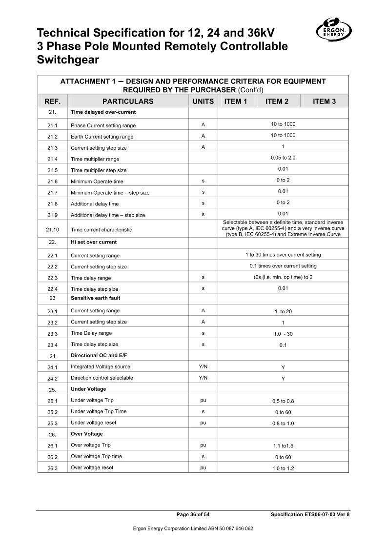
Technical Specification for 12, 24 and 36kV 3 Phase Pole Mounted Remotely Controllable Switchgear
Page 36 of 54 Specification ETS06-07-03 Ver 8
Ergon Energy Corporation Limited ABN 50 087 646 062
ATTACHMENT 1 – DESIGN AND PERFORMANCE CRITERIA FOR EQUIPMENT REQUIRED BY THE PURCHASER (Cont’d)
REF. PARTICULARS UNITS ITEM 1 ITEM 2 ITEM 3 21. Time delayed over-current
21.1 Phase Current setting range A 10 to 1000
21.2 Earth Current setting range A 10 to 1000
21.3 Current setting step size A 1
21.4 Time multiplier range 0.05 to 2.0
21.5 Time multiplier step size 0.01
21.6 Minimum Operate time s 0 to 2
21.7 Minimum Operate time – step size s 0.01
21.8 Additional delay time s 0 to 2
21.9 Additional delay time – step size s 0.01
21.10 Time current characteristic Selectable between a definite time, standard inverse curve (type A, IEC 60255-4) and a very inverse curve
(type B, IEC 60255-4) and Extreme Inverse Curve 22. Hi set over current
22.1 Current setting range 1 to 30 times over current setting
22.2 Current setting step size 0.1 times over current setting
22.3 Time delay range s (0s (i.e. min. op time) to 2
22.4 Time delay step size s 0.01
23 Sensitive earth fault
23.1 Current setting range A 1 to 20
23.2 Current setting step size A 1
23.3 Time Delay range s 1.0 - 30
23.4 Time delay step size s 0.1
24 Directional OC and E/F
24.1 Integrated Voltage source Y/N Y
24.2 Direction control selectable Y/N Y
25. Under Voltage
25.1 Under voltage Trip pu 0.5 to 0.8
25.2 Under voltage Trip Time s 0 to 60
25.3 Under voltage reset pu 0.8 to 1.0
26. Over Voltage
26.1 Over voltage Trip pu 1.1 to1.5
26.2 Over voltage Trip time s 0 to 60
26.3 Over voltage reset pu 1.0 to 1.2
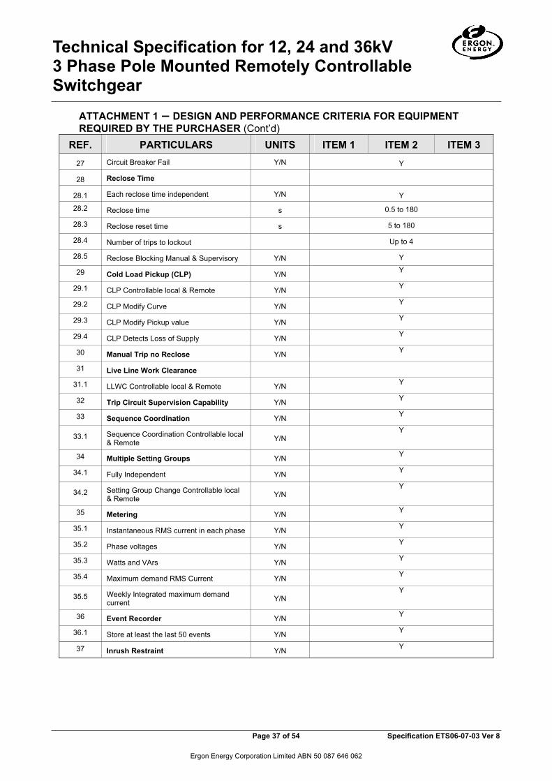
Technical Specification for 12, 24 and 36kV 3 Phase Pole Mounted Remotely Controllable Switchgear
Page 37 of 54 Specification ETS06-07-03 Ver 8
Ergon Energy Corporation Limited ABN 50 087 646 062
ATTACHMENT 1 – DESIGN AND PERFORMANCE CRITERIA FOR EQUIPMENT REQUIRED BY THE PURCHASER (Cont’d)
REF. PARTICULARS UNITS ITEM 1 ITEM 2 ITEM 3
27 Circuit Breaker Fail Y/N Y
28 Reclose Time
28.1 Each reclose time independent Y/N Y
28.2 Reclose time s 0.5 to 180
28.3 Reclose reset time s 5 to 180
28.4 Number of trips to lockout Up to 4
28.5 Reclose Blocking Manual & Supervisory Y/N Y
29 Cold Load Pickup (CLP) Y/N Y
29.1 CLP Controllable local & Remote Y/N Y
29.2 CLP Modify Curve Y/N Y
29.3 CLP Modify Pickup value Y/N Y
29.4 CLP Detects Loss of Supply Y/N Y
30 Manual Trip no Reclose Y/N Y
31 Live Line Work Clearance
31.1 LLWC Controllable local & Remote Y/N Y
32 Trip Circuit Supervision Capability Y/N Y
33 Sequence Coordination Y/N Y
33.1 Sequence Coordination Controllable local & Remote Y/N
Y
34 Multiple Setting Groups Y/N Y
34.1 Fully Independent Y/N Y
34.2 Setting Group Change Controllable local & Remote Y/N
Y
35 Metering Y/N Y
35.1 Instantaneous RMS current in each phase Y/N Y
35.2 Phase voltages Y/N Y
35.3 Watts and VArs Y/N Y
35.4 Maximum demand RMS Current Y/N Y
35.5 Weekly Integrated maximum demand current Y/N
Y
36 Event Recorder Y/N Y
36.1 Store at least the last 50 events Y/N Y
37 Inrush Restraint Y/N Y

Technical Specification for 12, 24 and 36kV 3 Phase Pole Mounted Remotely Controllable Switchgear
Page 38 of 54 Specification ETS06-07-03 Ver 8
Ergon Energy Corporation Limited ABN 50 087 646 062
ATTACHMENT 1 – DESIGN AND PERFORMANCE CRITERIA FOR EQUIPMENT REQUIRED BY THE PURCHASER (Cont’d)
38 OC and E/F independent separate trip sequences Y/N
Y
39 External Protection Trip Initiate Y/N Y
40 Software
40.1 no restrictions to PC numbers Y/N Y
40.2 Set, upload, control and Analyse Y/N Y
40.3 Fully function Local and remote Y/N Y
40.4 Microsoft Widows XP capable Y/N Y
40.5 Microsoft Widows 7 capable Y/N Y
41
Degree of protection of control unit in accordance with AS 1939. Where a supplier can demonstrate a lower IP rating will not affect the long term operation of the equipment, a lower IP rating may be accepted.
IP56D
42.1 (Max) Partial discharge level at 1.1XUm/√3 Phase to Earth –if solid dielectric insulation offered
pC 10
42.2 (Max) Partial discharge level at 1.1XUm Phase to Phase - if solid dielectric insulation offered
pC 10
ATTACHMENT 1 – DESIGN AND PERFORMANCE CRITERIA FOR EQUIPMENT REQUIRED BY THE PURCHASER (LBS/Sectionaliser) (Cont’d)
REF. PARTICULARS UNITS ITEM 4 ITEM 5 ITEM 6 1. Number of phases 3 3 3
2.1 Nominal rated voltage kV 11 22 33
2.2 Rated maximum voltage kV 12 24 36
3. Rated frequency Hz 50 50 50
4. Rated normal current (Minimum) A 400 400 400
5. Rated symmetrical interrupting current at rated voltage kA 12.5 12.5 12.5
6.1 Rated making current kA rms 12.5 12.5 12.5
6.2 Rated short time current for 3 sec. KA 12.5 12.5 12.5
7. Rated impulse withstand voltage kVp 95 150 170
8. Rated 1 minute power frequency withstand (dry kV 50 60 70
9.1
Minimum number of interruptions at rated short circuit current (up to X/R = 5) without requiring maintenance or inspection
100
9.2 Minimum number of load break operations at rated current before maintenance required
3000

Technical Specification for 12, 24 and 36kV 3 Phase Pole Mounted Remotely Controllable Switchgear
Page 39 of 54 Specification ETS06-07-03 Ver 8
Ergon Energy Corporation Limited ABN 50 087 646 062
ATTACHMENT 1 – DESIGN AND PERFORMANCE CRITERIA FOR EQUIPMENT REQUIRED BY THE PURCHASER (LBS/Sectionaliser) (Cont’d)
REF. PARTICULARS UNITS ITEM 4 ITEM 5 ITEM 6
10. Required interrupting medium SF6
11. Rated transformer magnetising breaking current A 10
12. Rated cable charging breaking current A 10
13. Rated operating sequence (total number of trips/counts to lock out) 4
14. Maximum break time s 0.05
15. Mechanical life - minimum number of close/open operations - without inspection
3000
16. Nominal system voltage (for HV closing solenoid operation - if applicable)
kV 11 22 33
17. Variation in nominal system voltage for guaranteed performance of pole mounted switchgear
% -20 / +10
18 HV bushings creepage length mm 290 540 820
19. Minimum taut string metal to metal clearance in air
19.1 Phase to phase mm 190 330 440
19.2 Phase to ground mm 160 280 380
19.3 Phase to Structure mm
19.1 Phase to phase mm 190 330 440
19.2 Phase to ground mm 160 280 380
19.3 Phase to Structure mm
20 Minimum length of umbilical (multi-core cable) between pole mounted switchgear tank and control unit
m 7
21 LBS Detection
21.1 3 phase and earth detection Y/N
21.2 Current setting range A 10 to 1000
21.3 Current setting step size A 1
21.4 Detection Time s 0.05 to 100
21.5 Detection Time step size s 0.01
21.6 Sequence Reset Time s 1 to 180
21.7 Reset Time Steps s 1
22 Manual Trip no Reclose Y/N Y
23 Live Line Work Clearance

Technical Specification for 12, 24 and 36kV 3 Phase Pole Mounted Remotely Controllable Switchgear
Page 40 of 54 Specification ETS06-07-03 Ver 8
Ergon Energy Corporation Limited ABN 50 087 646 062
REF. PARTICULARS UNITS ITEM 4 ITEM 5 ITEM 6 23.1 LLWC Controllable local & Remote Y/N Y
24 Trip Circuit Supervision Capability Y/N Y
25 Sequence Coordination Y/N Y
25.1 Sequence Coordination Controllable local & Remote Y/N Y
26 Multiple Setting Groups Y/N Y
26.1 Fully Independent Y/N Y
26.2 Setting Group Change Controllable local & Remote Y/N Y
27 Metering Y/N Y
27.1 Instantaneous RMS current in each phase Y/N Y
27.2 Phase voltages Y/N Y
27.3 Watts and VArs Y/N Y
27.4 Maximum demand RMS Current Y/N Y
27.5 Weekly Integrated maximum demand current Y/N Y
28 Event Recorder Y/N Y
28.1 Store at least the last 50 events Y/N Y
29 Inrush Restraint Y/N Y
30 OC and E/F independent separate trip sequences Y/N Y
31 External Protection Trip Initiate Y/N Y
32 Software
32.1 no restrictions to PC numbers Y/N Y
32.2 Set, upload, control and Analyse Y/N Y
32.3 Fully function Local and remote Y/N Y
32.4 Microsoft Widows XP capable Y/N Y
32.5 Microsoft Widows 7 capable Y/N Y
33
Degree of protection of control unit in accordance with AS 1939. Where a supplier can demonstrate a lower IP rating will not affect the long term operation of the equipment, a lower IP rating may be accepted.
IP56D
34.1 (Max) Partial discharge level at 1.1XUm/√3 Phase to Earth –if solid dielectric insulation offered
pC 10
34.2 (Max) Partial discharge level at 1.1XUm Phase to Phase - if solid dielectric insulation offered
pC 10

Technical Specification for 12, 24 and 36kV 3 Phase Pole Mounted Remotely Controllable Switchgear
Page 41 of 54 Specification ETS06-07-03 Ver 8
Ergon Energy Corporation Limited ABN 50 087 646 062
ATTACHMENT 1 – DESIGN AND PERFORMANCE CRITERIA FOR EQUIPMENT REQUIRED BY THE PURCHASER (Auxiliary Voltage Transformer) (Cont’d)
REF. PARTICULARS UNITS ITEM 7 ITEM 8 ITEM 9 1. Number of phases 1 1 1
2.1 Nominal rated primary voltage kV 11 22 33
2.2 Rated maximum rated primary voltage kV 12 24 36
2.3 Rated maximum rated primary voltage V 240 240 240
3. Rated frequency Hz 50 50 50
4. Rated ouput (minimum) VA 50 50 50
5 Class outdoor outdoor outdoor
5. Rated symmetrical interrupting current at rated voltage kA 12.5 12.5 12.5
6. Rated impulse withstand voltage kVp 95 150 170
7. Rated 1 minute power frequency withstand (dry kV 28 50 70
8 Clearance to HV terminals
8.1 Phase to phase mm 190 330 440
8.2 Phase to ground mm 160 280 380
SIGNATURE OF TENDERER: _________________________________
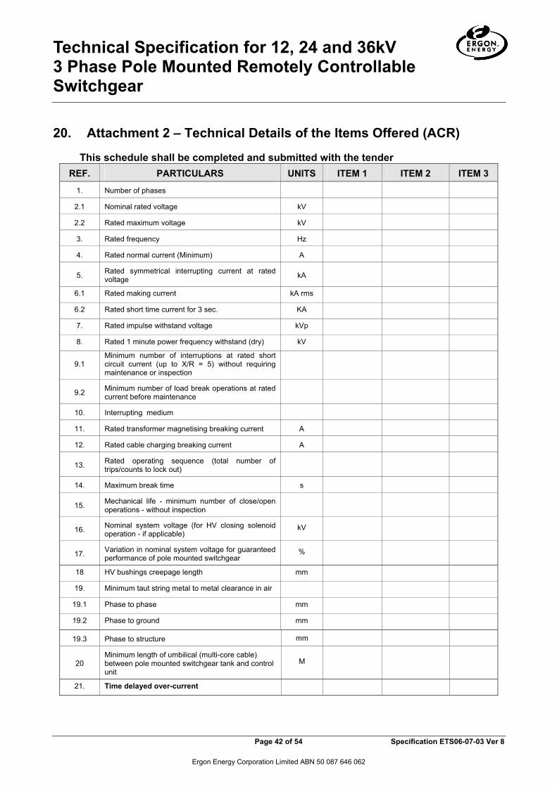
Technical Specification for 12, 24 and 36kV 3 Phase Pole Mounted Remotely Controllable Switchgear
Page 42 of 54 Specification ETS06-07-03 Ver 8
Ergon Energy Corporation Limited ABN 50 087 646 062
20. Attachment 2 – Technical Details of the Items Offered (ACR)
This schedule shall be completed and submitted with the tender REF. PARTICULARS UNITS ITEM 1 ITEM 2 ITEM 3
1. Number of phases
2.1 Nominal rated voltage kV
2.2 Rated maximum voltage kV
3. Rated frequency Hz
4. Rated normal current (Minimum) A
5. Rated symmetrical interrupting current at rated voltage kA
6.1 Rated making current kA rms
6.2 Rated short time current for 3 sec. KA
7. Rated impulse withstand voltage kVp
8. Rated 1 minute power frequency withstand (dry) kV
9.1 Minimum number of interruptions at rated short circuit current (up to X/R = 5) without requiring maintenance or inspection
9.2 Minimum number of load break operations at rated current before maintenance
10. Interrupting medium
11. Rated transformer magnetising breaking current A
12. Rated cable charging breaking current A
13. Rated operating sequence (total number of trips/counts to lock out)
14. Maximum break time s
15. Mechanical life - minimum number of close/open operations - without inspection
16. Nominal system voltage (for HV closing solenoid operation - if applicable)
kV
17. Variation in nominal system voltage for guaranteed performance of pole mounted switchgear
%
18 HV bushings creepage length mm
19. Minimum taut string metal to metal clearance in air
19.1 Phase to phase mm
19.2 Phase to ground mm
19.3 Phase to structure mm
20 Minimum length of umbilical (multi-core cable) between pole mounted switchgear tank and control unit
M
21. Time delayed over-current

Technical Specification for 12, 24 and 36kV 3 Phase Pole Mounted Remotely Controllable Switchgear
Page 43 of 54 Specification ETS06-07-03 Ver 8
Ergon Energy Corporation Limited ABN 50 087 646 062
ATTACHMENT 2 - TECHNICAL DETAILS OF THE ITEMS OFFERED (Cont’d)
REF. PARTICULARS UNITS ITEM 1 ITEM 2 ITEM 3 21.1 Phase Current setting range A
21.2 Earth Current setting range A
21.3 Current setting step size A
21.4 Time multiplier range
21.5 Time multiplier step size
21.6 Minimum Operate time s
21.7 Minimum Operate time – step size s
21.8 Additional delay time s
21.9 Additional delay time – step size s
21.10 Time current characteristic
22. Hi set over current
22.1 Current setting range
22.2 Current setting step size
22.3 Time delay range s
22.4 Time delay step size s
23 Sensitive earth fault
23.1 Current setting range A
23.2 Current setting step size A
23.3 Time Delay range s
23.4 Time delay step size s
24 Directional OC and E/F
24.1 Integrated Voltage source Y/N
24.2 Direction control selectable Y/N
25. Under Voltage
25.1 Under voltage Trip pu
25.2 Under voltage Trip Time s
25.3 Under voltage reset pu
26. Over Voltage
26.1 Over voltage Trip pu
26.2 Over voltage Trip time s
26.3 Over voltage reset pu
27 Circuit Breaker Fail Y/N
28 Reclose Time
28.1 Each reclose time independent Y/N

Technical Specification for 12, 24 and 36kV 3 Phase Pole Mounted Remotely Controllable Switchgear
Page 44 of 54 Specification ETS06-07-03 Ver 8
Ergon Energy Corporation Limited ABN 50 087 646 062
ATTACHMENT 2 - TECHNICAL DETAILS OF THE ITEMS OFFERED (Cont’d) REF. PARTICULARS UNITS ITEM 1 ITEM 2 ITEM 3
28.2 Reclose time s
28.3 Reclose reset time s
28.4 Number of trips to lockout
28.5 Reclose Blocking Manual & Supervisory Y/N
29 Cold Load Pickup Y/N
29.1 CLP Controllable local & Remote Y/N
29.2 CLP Modify Curve Y/N
29.3 CLP Modify Pickup value Y/N
29.4 CLP Detects Loss of Supply Y/N
30 Manual Trip no Reclose Y/N
31 Live Line Work Clearance
31.1 LLWC Controllable local & Remote Y/N
32 Trip Circuit Supervision Capability Y/N
33 Sequence Coordination Y/N
33.1 Sequence Coordination Controllable local & Remote Y/N
34 Multiple Setting Groups Y/N
34.1 Fully Independent Y/N
34.2 Setting Group Change Controllable local & Remote Y/N
35 Metering Y/N
35.1 Instantaneous RMS current in each phase Y/N
35.2 Phase voltages Y/N
35.3 Watts and VArs Y/N
35.4 Maximum demand RMS Current Y/N
35.5 Weekly Integrated maximum demand current Y/N
36 Event Recorder Y/N
36.1 Store at least the last 50 events Y/N
37 Inrush Restraint Y/N
38 OC and E/F independent separate trip sequences Y/N
39 External Protection Trip Initiate Y/N
40 Software
40.1 no restrictions to PC numbers Y/N
40.2 Set, upload, control and Analyse Y/N
40.3 Fully function Local and remote Y/N
40.4 Microsoft Widows XP capable Y/N
40.5 Microsoft Widows 7 capable Y/N

Technical Specification for 12, 24 and 36kV 3 Phase Pole Mounted Remotely Controllable Switchgear
Page 45 of 54 Specification ETS06-07-03 Ver 8
Ergon Energy Corporation Limited ABN 50 087 646 062
ATTACHMENT 2 - TECHNICAL DETAILS OF THE ITEMS OFFERED (Cont’d)
REF. PARTICULARS UNITS ITEM 1 ITEM 2 ITEM 3
41
Degree of protection of control unit in accordance with AS 1939. Where a supplier can demonstrate a lower IP rating will not affect the long term operation of the equipment, a lower IP rating may be accepted.
42.1 (Max) Partial discharge level at 1.1XUm/√3 Phase to Earth –if solid dielectric insulation offered
pC
42.2 (Max) Partial discharge level at 1.1XUm Phase to Phase - if solid dielectric insulation offered pC
43 Recloser housing material
44 Control box material
45
DC Supply (Control & Protection) - Voltage - Make of batteries - Type - Capacity - Life - No of reclose sequences possible within 36
hours after the loss of ac supply
Volts
Amp-Hr Years
46
DC Supply ( Communication)
- Is this taken off 30 above
- Voltage
- Discharge rate (average)
- Discharge rate (maximum)
- Carryover capacity at average discharge rate after loss of ac supply
Yes/No Volts
A A
Hours
47 Compatibility with Schweitzer Engineering Laboratories SEL-351R Recloser Control Unit
Yes/No
47.1
47.2
Can the reclosers offered be controlled using a SEL-351R Recloser Control Unit?
If Yes, were they type tested with the SEL-351R Controller (Test Certificates required)
Yes/No
Yes/No
SIGNATURE OF TENDERER: _________________________________

Technical Specification for 12, 24 and 36kV 3 Phase Pole Mounted Remotely Controllable Switchgear
Page 46 of 54 Specification ETS06-07-03 Ver 8
Ergon Energy Corporation Limited ABN 50 087 646 062
ATTACHMENT 2 - TECHNICAL DETAILS OF THE ITEMS OFFERED (LBS/Sectionaliser) (Cont’d)
REF. PARTICULARS UNITS ITEM 4 ITEM 5 ITEM 6 1. Number of phases
2.1 Nominal rated voltage kV
2.2 Rated maximum voltage kV
3. Rated frequency Hz
4. Rated normal current (Minimum) A
5. Rated symmetrical interrupting current at rated voltage kA
6.1 Rated making current kA rms
6.2 Rated short time current for 3 sec. KA
7. Rated impulse withstand voltage kVp
8. Rated 1 minute power frequency withstand (dry) kV
9.1 Minimum number of interruptions at rated short circuit current (up to X/R = 5) without requiring maintenance or inspection
9.2 Minimum number of load break operations at rated current before maintenance
10. Interrupting medium
11. Rated transformer magnetising breaking current A
12. Rated cable charging breaking current A
13. Rated operating sequence (total number of trips/counts to lock out)
14. Maximum break time s
15. Mechanical life - minimum number of close/open operations - without inspection
16. Nominal system voltage (for HV closing solenoid operation - if applicable)
kV
17. Variation in nominal system voltage for guaranteed performance of pole mounted switchgear
%
18 HV bushings creepage length mm
19. Minimum taut string metal to metal clearance in air
19.1 Phase to phase mm
19.2 Phase to ground mm
19.3 Phase to structure mm
20 Minimum length of umbilical (multi-core cable) between pole mounted switchgear tank and control unit M
21 LBS Detection
21.1 3 phase and earth detection Y/N
21.2 Current setting range A
21.3 Current setting step size A
21.4 Detection Time s
21.5 Detection Time step size s

Technical Specification for 12, 24 and 36kV 3 Phase Pole Mounted Remotely Controllable Switchgear
Page 47 of 54 Specification ETS06-07-03 Ver 8
Ergon Energy Corporation Limited ABN 50 087 646 062
ATTACHMENT 2 - TECHNICAL DETAILS OF THE ITEMS OFFERED (LBS/Sectionaliser) (Cont’d)
REF. PARTICULARS UNIT ITEM 4 ITEM 5 ITEM 6 21.6 Sequence Reset Time s
21.7 Reset Time Steps s
22 Manual Trip no Reclose Y/N
23 Live Line Work Clearance
23.1 LLWC Controllable local & Remote Y/N
24 Trip Circuit Supervision Capability Y/N
25 Sequence Coordination Y/N
25.1 Sequence Coordination Controllable local & Remote Y/N
26 Multiple Setting Groups Y/N
26.1 Fully Independent Y/N
26.2 Setting Group Change Controllable local & Remote Y/N
27 Metering Y/N
27.1 Instantaneous RMS current in each phase Y/N
27.2 Phase voltages Y/N
27.3 Watts and VArs Y/N
27.4 Maximum demand RMS Current Y/N
27.5 Weekly Integrated maximum demand current Y/N
28 Event Recorder Y/N
28.1 Store at least the last 50 events Y/N
29 Inrush Restraint Y/N
30 OC and E/F independent separate trip sequences Y/N
31 External Protection Trip Initiate Y/N
32 Software
32.1 no restrictions to PC numbers Y/N
32.2 Set, upload, control and Analyse Y/N
32.3 Fully function Local and remote Y/N
32.4 Microsoft Widows XP capable Y/N
32.5 Microsoft Widows 7 capable Y/N
33 Degree of protection of control unit in accordance with AS 1939. Where a supplier can demonstrate a lower IP rating will not affect the long term operation of the equipment, a lower IP rating may be accepted.
34.1 (Max) Partial discharge level at 1.1XUm/√3 Phase to Earth –if solid dielectric insulation offered pC
34.2 (Max) Partial discharge level at 1.1XUm Phase to Phase - if solid dielectric insulation offered pC
35 Recloser housing material
36 Control box material

Technical Specification for 12, 24 and 36kV 3 Phase Pole Mounted Remotely Controllable Switchgear
Page 48 of 54 Specification ETS06-07-03 Ver 8
Ergon Energy Corporation Limited ABN 50 087 646 062
ATTACHMENT 2 - TECHNICAL DETAILS OF THE ITEMS OFFERED (LBS/Sectionaliser) (Cont’d)
REF. PARTICULARS UNITS ITEM 4 ITEM 5 ITEM 6
33
DC Supply (Control & Protection) - Voltage - Make of batteries - Type - Capacity - Life - No of reclose sequences
possible within 36 hours after the loss of ac supply
Volts
Amp-Hr
Years
34
DC Supply ( Communication)
- Is this taken off 30 above
- Voltage
- Discharge rate (average)
- Discharge rate (maximum)
- Carryover capacity at average discharge rate after loss of ac supply
Yes/No Volts
A A
Hours
35 Compatibility with Schweitzer Engineering Laboratories SEL-351R Recloser Control Unit
Yes/No
36 Can the reclosers offered be controlled using a SEL-351R Recloser Control Unit?
Yes/No
37 If Yes, were they type tested with the SEL-351R Controller (Test Certificates required)
Yes/No
SIGNATURE OF TENDERER: _________________________________

Technical Specification for 12, 24 and 36kV 3 Phase Pole Mounted Remotely Controllable Switchgear
Page 49 of 54 Specification ETS06-07-03 Ver 8
Ergon Energy Corporation Limited ABN 50 087 646 062
ATTACHMENT 2 – DESIGN AND PERFORMANCE CRITERIA FOR EQUIPMENT REQUIRED BY THE PURCHASER (Auxiliary Voltage Transformer) (Cont’d)
REF. PARTICULARS UNITS ITEM 7 ITEM 8 ITEM 9
1 Type/Model Number
2 Manufacturer
3 Country of Manufacture
4 Class Outdoor
5 Is the VT designed, manufactured and tested in accordance with AS 60044.2
Yes/No
6 Number of phases
7.1 Rated primary voltage kV
7.2 Rated maximum primary voltage Um kV
7.3 Rated secondary voltage V
8 Rated frequency Hz
9 Rated output (minimum) VA
10 Rated impulse withstand voltage kVp
11 Rated power frequency withstand (dry) kVrms
12 Rated power frequency withstand (wet) kVrms
13.1 Clearance to HV terminals
13.2 Phase to phase mm
13.3 Phase to ground mm
14 Bushing type
14.1 Bushing creepage dist ph-ph mm
14.2 Bushing creepage dist ph-ground mm
14.3 Bushing colour
15 Partial discharge levels
15.1 Phase to earth @ 1.2 Um/√3 pC
15.2 Phase to phase @ 1.2Um pC
16 Secondary fuse in VT terminal box Yes/No
17.1 Make/type of fuse
17.2 Fuse rating A
SIGNATURE OF TENDERER: _________________________________
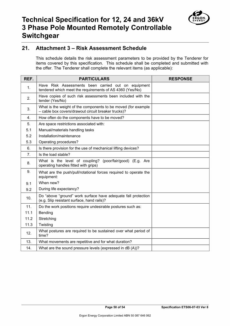
Technical Specification for 12, 24 and 36kV 3 Phase Pole Mounted Remotely Controllable Switchgear
Page 50 of 54 Specification ETS06-07-03 Ver 8
Ergon Energy Corporation Limited ABN 50 087 646 062
21. Attachment 3 – Risk Assessment Schedule
This schedule details the risk assessment parameters to be provided by the Tenderer for items covered by this specification. This schedule shall be completed and submitted with the offer. The Tenderer shall complete the relevant items (as applicable):
REF. PARTICULARS RESPONSE
1. Have Risk Assessments been carried out on equipment tendered which meet the requirements of AS 4360 (Yes/No)
2. Have copies of such risk assessments been included with the tender (Yes/No)
3. What is the weight of the components to be moved (for example – cable box covers/drawout circuit breaker trucks)?
4. How often do the components have to be moved? 5.
5.1 5.2 5.3
Are space restrictions associated with: Manual/materials handling tasks Installation/maintenance Operating procedures?
6. Is there provision for the use of mechanical lifting devices? 7. Is the load stable?
8. What is the level of coupling? (poor/fair/good) (E.g. Are operating handles fitted with grips)
9.
9.1 9.2
What are the push/pull/rotational forces required to operate the equipment: When new? During life expectancy?
10. Do “above “ground” work surface have adequate fall protection (e.g. Slip resistant surface, hand rails)?
11. 11.1 11.2 11.3
Do the work positions require undesirable postures such as: Bending Stretching Twisting
12. What postures are required to be sustained over what period of time?
13. What movements are repetitive and for what duration? 14. What are the sound pressure levels (expressed in dB (A))?

Technical Specification for 12, 24 and 36kV 3 Phase Pole Mounted Remotely Controllable Switchgear
Page 51 of 54 Specification ETS06-07-03 Ver 8
Ergon Energy Corporation Limited ABN 50 087 646 062
ATTACHMENT 3 - RISK ASSESSMENT (Cont’d) REF. PARTICULARS RESPONSE 15.
15.1 15.2 15.3 15.4 15.5 15.6 15.7
What hazardous substances are used/produces (including after failure) such as: Dust Gas Fume Emissions Mist Liquid Solids
16. Are the hazardous substances controls compatible with normal operational requirements?
17. Is a Safety Data Sheet for all hazardous substances provided? 18. What are the expected hazardous changes/by-products
associated with the deterioration of a substance?
19. Is there any possible contact with energised components? 20. What are the levels of radiation emitted? 21. When in service, are any normally accessible areas hot/cold
enough to be a hazard?
22. Are there any biological hazards? 23. Are there any mechanical hazards (e.g. Nip in points, exposed
moving components)?
24. Are mechanical hazards appropriately controlled (e.g. guarding, lockouts)?
25. Are load limits established and clearly identified? 26. Are gauges clearly visible and easily interpreted? 27. Are control movements consistent with established Australian
conventions (e.g. switch “UP” position is “OFF”)?
28. What is the degree of whole body or hand/arm vibration (Hz) 29. Are projectiles generated? 30 Are special tools required/identified/supplied? 31. What are the hazards associated with equipment failure?
SIGNATURE OF TENDERER: _________________________________

Technical Specification for 12, 24 and 36kV 3 Phase Pole Mounted Remotely Controllable Switchgear
Page 52 of 54 Specification ETS06-07-03 Ver 8
Ergon Energy Corporation Limited ABN 50 087 646 062
22. Attachment 4 – Technical Document Checklist
This schedule details parameters referred to within the body of the specification for which a response by suppliers is requested. This schedule shall be completed and submitted with the offer. Have the following information provided with the tender documentation?
PARTICULARS CLAUSE ANSWER (Yes/No)
Internal arc containment classification status of offered equipment 5.2
Recommended access restrictions when installed in substations-if applicable
5.2
Is the offered items “Registrable Plant” under the Qld WH7S Reg 1997 5.3
Is explanation of why equipment is not “Registrable Plant” attached? 5.3
Consequence of loss of vacuum in interrupting chamber for item 1 to 3 5.4.1
Consequence of loss of SF6 gas in interrupting chamber for item 4 to 6 5.4.2
Consequences of loss of SF6 in insulating medium(if applicable) 5.5
If epoxy insulated items offered, are full details of material, service history/number ouf units in service provided
5.5
Detailed drawing of recloser with surge arresters fitted 5.7
Information on internal pressure relief techniques 5.8
Ability of equipment inside the control box to withstand heating due to direct solar radiation
5.9
Dimensional drawings of HV bushings 5.15
Details on mitigation of effects due to system disturbances on protection, control and communication equipment
5.19
Details of expected service life of batteries 5.19
DNP3.0 device profile be included in the Tender submission 5.21
Max variation in voltage/phase angle across an open LBS that the switch can safely close/open and test reports
5.23
Desirable optional features offered 5.27
Type test certificates 6.1
Availability of Millivolt drop test 6.3.1
Risk assessment documentation 7.& Attachment 3
QA Certification of Supplier and Manufacturer 8.2
Availability of samples for evaluation 9
Service history details and contact names and telephone numbers 11
Reliability information 12
Availability of training materials 13
Comments on environmental soundness of equipment/recycling of SF6 at the end of service life and MSDS for chemical substances
14

Technical Specification for 12, 24 and 36kV 3 Phase Pole Mounted Remotely Controllable Switchgear
Page 53 of 54 Specification ETS06-07-03 Ver 8
Ergon Energy Corporation Limited ABN 50 087 646 062
Availability of drawings and Manuals as required 15.1.1 15.1.2
Completed Attachments 2 and 4 of this specification 15.2
Completed Attachment 2 of Surge Arrester Specification ETS09-01-01(3) 5.16
Details on Warranty offered 16
List of spare parts and pricing 17 NAME OF TENDERER: ADDRESS OF TENDERER: SIGNATURE: FOR AND ON BEHALF OF TENDERER DATE: ______________________

Technical Specification for 12, 24 and 36kV 3 Phase Pole Mounted Remotely Controllable Switchgear
Page 54 of 54 Specification ETS06-07-03 Ver 8
Ergon Energy Corporation Limited ABN 50 087 646 062
23. Attachment 5 – Nameplate Details
The successful Tenderer shall complete the following spreadsheETSand return to the Purchaser by electronic mail to: [email protected] with each delivery as applicable.
ACR Nameplate Details.xls
LBS/Sectionaliser Nameplate Details.xls
![Olivio Grande - Candelabra Pole Top [OLG] selux Grande - Candelabra Pole Top Refer to individual pole specification sheets for construction details, ... Olivio Grande - Candelabra](https://static.fdocuments.in/doc/165x107/5adea1547f8b9ad66b8bc8b5/olivio-grande-candelabra-pole-top-olg-grande-candelabra-pole-top-refer-to.jpg)