Technical Service Manual - Marcone Servicers...
66
Publication #5995505426 P/N 316439260 May 2009 Technical Service Manual High Speed Convection Microwave Oven Model E30SO75ESS
Transcript of Technical Service Manual - Marcone Servicers...

Publication #5995505426 P/N 316439260 May 2009
Technical Service Manual High Speed Convection
Microwave Oven
ModelE30SO75ESS


Basic Information
1-1
Safe Servicing Practices
Avoid personal injury and/or property damage by observing important Safe Servicing Practices. Following are some limited examples of safe practices:
1. DO NOT attempt a product repair if you have any doubts as to your ability to complete the repair in a safe and satisfactory manner.
2. Always Use The Correct Replacement Parts as indicated in the parts documentation. Substitutions may defeat compliance with Safety Standards Set For Home Appliances. Do not exceed maximum recommended wattage on light bulb replacements. Doing so could blow fuses and/or damage transformers.
3. Before servicing or moving an appliance: • Remove power cord from the electrical outlet, trip circuit breaker to the OFF position, or remove fuse.
4. Never interfere with the proper operation of any safety device.
5. Use ONLY REPLACEMENT PARTS CATALOGED FOR THIS APPLIANCE. Substitutions may defeat compliance with Safety Standards Set For Home Appliances.
6. GROUNDING: The standard color coding for safety ground wires is GREEN, or GREEN with YELLOW STRIPES. Ground leads are not to be used as current carrying conductors. It is EXTREMELY important that the service technician reestablish all safety grounds prior to completion of service. Failure to do so will create a hazard.
7. Prior to returning the product to service, ensure that: • All electrical connections are correct and secure.
• All electrical leads are properly dressed and secured away from sharp edges, high-temperature components, and moving parts.
• All non-insulated electrical terminals, connectors, heaters, etc. are adequately spaced away from all metal parts and panels.
• All safety grounds (both internal and external) are correctly and securely connected.
• All panels are properly and securely reassembled.
© 2008 Electrolux Home Products, Inc.

1-2
Basic Information
This Manual has been prepared to provide Electrolux Service Personnel with Operation and Service Information for an Electrolux ICON High Speed Convection Microwave Oven Model EW30SO75ESS.
Table of ContentsSection 1 Basic Information
Safe Servicing Practices .......................................... 1-1Table of Contents .................................................... 1-2Warnings and Safety Information ............................ 1-3Precautions To Be Observed Before And During Servicing To Avoid Possible Exposure To Excessive Microwave Energy .................................. 1-4Before Servicing ...................................................... 1-4Danger High Voltage ............................................... 1-4Before Servicing ...................................................... 1-5When Testing Is Completed .................................... 1-5Microwave Measurement Procedure USA .............. 1-6Microwave Measurement Procedure Canada ......... 1-7Product Specification ............................................... 1-8Grounding Instructions ............................................ 1-9Oven Diagram ......................................................... 1-10
Section 2 OperationSection 2 Operation
Operating Sequence Description ............................. 2-1 Off Condition ........................................................ 2-1 Cooking Condition ................................................ 2-1Variable Cooking ..................................................... 2-2 Preheat Convection Cooking Condition ............... 2-2 Convection Cooking Condition ............................. 2-2 Speed Bake Cooking............................................ 2-3 Speed Grill Cooking ............................................. 2-3 Speed Roast Cooking .......................................... 2-3 Speed Cooking Of Automatic Cooking ................. 2-3 Microwave Options Of Automatic Cooking ........... 2-3Oven Condition Schematics .................................... 2-4Fire Sensing Feature (Microwave Mode .................. 2-6 Component Descriptions ......................................... 2-7Door Open Mechanism ............................................ 2-7Door Sensing And Secondary Interlock Switches ... 2-7Monitor Switch ......................................................... 2-7Thermistor ............................................................... 2-8Magnetron Temperature Fuse ................................. 2-8Top Heater Thermal Cut-Out ................................... 2-8Side Heater Thermal Cut-Out .................................. 2-8Top Heating Element ............................................... 2-8Side Heating Element ............................................... 2-8Turntable Motor ........................................................ 2-8Fan Motor (Magnetron Side) .................................... 2-8Fan Motor (Power Transformer Side) ....................... 2-9Convection Cooking System .................................... 2-9Damper Open-Close Mechanism ............................. 2-10
Section 3 Troubleshooting and Testing
Warnings and Cautions ........................................... 3-1Troubleshooting Guide Chart .................................. 3-2Test Procedures ...................................................... 3-3
Section 4 Component Teardown
Warnings and Cautions ........................................... 4-1Outer Case Removal ............................................... 4-2Terminal Insulator Removal ..................................... 4-2Power Supply Cord Removal .................................. 4-2Back Plate Removal ................................................ 4-3Power Transformer Removal ................................... 4-3Magnetron Removal ................................................ 4-4High Voltage Capacitor And HighVoltage Rectifier Assembly Removal ...................... 4-4Fan Motor Removal ................................................. 4-5 Power Transformer Side ...................................... 4-5 Power Transformer Side ...................................... 4-5Solid-State Relay (Magnetron Side) Removal ......... 4-5Damper Motor And Damper Switch Removal .......... 4-6Heater Duct Left Assembly, Heater Duct Upper Assembly And Convection Duct Assembly ............. 4-6Side Heating Element Removal ............................... 4-7Turntable Motor Removal ........................................ 4-7Door Sensing Switch, Secondary Interlock Switch and Monitor Switch Replacement/ Adjustment ........ 4-8Door Replacement And Adjustment ........................ 4-9
Section 5 Wire Diagrams
Wiring Schematic Oven Off Condition ..................... 5-1Backlit LED Diagram ............................................... 5-2Function LED Diagram ............................................ 5-3Pictorial Diagram ..................................................... 5-4Power Unit Circuit .................................................... 5-5CPU Unit Circuit ...................................................... 5-6Key Function ............................................................ 5-7
Section 6 Parts List
Parts Listing ............................................................. 6-1Control and Door Parts Exploded View ................... 6-3Cabinet And Frame Parts Exploded View ............... 6-4Packing and Accessories Exploded View ................ 6-5

Basic Information
1-3
THIS SERVICE MANUAL IS INTENDED FOR USE BY PERSONS HAVING ELECTRICAL AND MECHANICAL TRAINING AND A LEVEL OF KNOWLEDGE OF THESE SUBJECTS GENERALLY CONSIDERED ACCEPTABLE IN THE APPLIANCE REPAIR TRADE. ELECTROLUX HOME PRODUCTS CANNOT BE RESPONSIBLE, NOR ASSUME ANY LIABILITY, FOR INJURY OR DAMAGE OF ANY KIND ARISING FROM THE USE OF THIS MANUAL.
NEVER OPERATE THE OVEN UNTIL THE FOLLOWING POINTS ARE ENSURED.
(A) THE DOOR IS TIGHTLY CLOSED.(B) THE DOOR BRACKETS AND HINGES ARE NOT DEFECTIVE.(C) THE DOOR PACKING IS NOT DAMAGED.(D) THE DOOR IS NOT DEFORMED OR WARPED.(E) THERE IS NO OTHER VISIBLE DAMAGE WITH THE OVEN.
SERVICING AND REPAIR WORK MUST BE CARRIED OUT ONLY BY TRAINED SERVICE PERSONNEL.
CERTAIN INITIAL PARTS ARE INTENTIONALLY NOT GROUNDED AND PRESENT A RISK OF ELECTRICAL SHOCK ONLY DURING SERVICING. SERVICE PERSONNEL - DO NOT CONTACT THE FOLLOWING PARTS WHILE THE APPLIANCE IS ENERGIZED:
INVERTER UNIT, THAT INCLUDES HIGH VOLTAGE CAPACITOR, HIGH VOLTAGE POWER TRANSFORMER, HIGH VOLTAGE RECTIFIER, HEAT SINK, ETC., AND MAGNETRON, HIGH VOLTAGE HARNESS ETC.;IF PROVIDED, FAN ASSEMBLY, COOLING FAN MOTOR.
ALL THE PARTS MARKED “*” ON PARTS LIST ARE USED AT VOLTAGES MORE THAN 250V.
REMOVAL OF THE OUTER WRAPPER GIVES ACCESS TO VOLTAGE ABOVE 250V.
ALL THE PARTS MARKED “Ä” ON PARTS LIST MAY CAUSE UNDUE MICROWAVE EXPOSURE, BY THEMSELVES, OR WHEN THEY ARE DAMAGED, LOOSENED OR REMOVED.

1-4
Basic Information
Precautions To Be Observed Before And During Servicing To Avoid Possible Exposure To Excessive Microwave Energy(a) Do not operate or allow the oven to be operated with the door open.(b) Make the following safety checks on all ovens to be serviced before activating the magnetron or other microwave source, and make repairs as necessary: (1) interlock operation, (2) proper door closing, (3) seal and sealing surfaces (arcing, wear, and other damage), (4) damage to or loosening of hinges and latches, (5) evidence of dropping or abuse.(c) Before turning on microwave power for any service test or inspection within the microwave generating compartments, check the magnetron, wave guide or transmission line, and cavity for proper alignment, integrity, and connections.(d) Any defective or misadjusted components in the interlock, monitor, door seal, and microwave generation and transmission systems shall be repaired, replaced, or adjusted by procedures described in this manual before the oven is released to the owner.(e) A microwave leakage check to verify compliance with the Federal Performance Standard should be performed on each oven prior to release to the owner.
Before ServicingBefore servicing an operative unit, perform a microwave emission check as per the Microwave MeasurementProcedure outlined in this service manual.
If microwave emissions level is in excess of the specified limit, contact ELECTROLUX HOME PRODUCTS, INC.immediately.
If the unit operates with the door open, service person should:
1) Tell the user not to operate the oven. 2) Contact Electrolux HOME PRODUCTS, INC. and Food and Drug Administration’s Center for Devices and Radiological Health immediately.
Service personnel should inform ELECTROLUX HOME PRODUCTS, INC. of any certified unit found with emissions in excess of 4mW/cm2. The owner of the unit should be instructed not to use the unit until the oven has been brought into compliance.
DANGER HIGH VOLTAGEDo not energize a microwave oven with the outer case cabinet removed, because a microwave oven generates high voltage in the circuit.
If you intend to operate the oven employing the high frequency switching power converter circuit, you should take special precautions to avoid an electrical shock hazard.
The high voltage transformer, high voltage capacitor and high voltage diode have energized high voltage potential of approximately 8KV.
The aluminium heat sink is connected to the switching power transistor collector pole, and has an energized high voltage potential of approximately 650V peak.
DO NOT ACCESS THE HIGH VOLTAGE TRANSFORMER, HIGH VOLTAGE CAPACITOR, HIGH VOLTAGEDIODE AND HEAT SINK WHEN THE POWER SUPPLY IS CONNECTED TO AN ELECTRICAL OUTLET.

Basic Information
1-5
Before Servicing1. Disconnect the power supply cord, and then remove outer case.2. Open the door and block it open.3. Discharge high voltage capacitor.
Whenever troubleshooting is performed, the power supply must be disconnected. It may, in some cases, be necessary to connect the power supply after the outer case has been removed, in this event:
1. Disconnect the oven power supply cord and then remove the outer case.
2. Open the door and block it open.
3. Discharge high voltage capacitor.
4. Disconnect leads to the primary of the inverter unit.
5. Ensure that these leads remain isolated from other components and oven chassis by using insulation tape.
6. After that procedure, reconnect the power supply cord.
When Testing Is Completed1. Disconnect the power supply cord, and then remove outer case.
2. Open the door and block it open.
3. Discharge high voltage capacitor.
4. Reconnect leads to the primary of the inverter unit.
5. Reinstall the outer case (cabinet).
6. Reconnect the power supply cord after the outer case is installed.
7. Run the oven and check all functions.
After repairing
1. Reconnect all leads removed from components during testing.
2. Reinstall the outer case (cabinet).
3. Reconnect the power supply cord after the outer case is installed.
4. Run the oven and check all functions. Microwave ovens should not be run empty. To test for the presence of microwave energy within a cavity, place a cup of cold water on the oven turntable, close the door and set the power to HIGH and then set the microwave timer for two (2) minutes. When the two minutes has elapsed (timer at zero) carefully check that the water is now hot. If the water remains cold carry out Before Servicing procedure and re-examine the connections to the component being tested.
MICROWAVE OVENS CONTAIN CIRCUITRY CAPABLE OF PRODUCING VERY HIGH VOLTAGE AND CURRENT. CONTACT WITH THE FOLLOWING PARTS MAY RESULT IN A SEVERE, POSSIBLY FATAL, ELECTRICAL SHOCK.
INVERTER UNIT, THAT INCLUDES HIGH VOLTAGE CAPACITOR,HIGH VOLTAGE POWER TRANSFORMER, HIGH VOLTAGE RECTIFIER, HEAT SINK ETC., AND MAGNETRON, HIGH VOLTAGE HARNESS ETC..READ THE SERVICE MANUAL CAREFULLY AND FOLLOW ALLINSTRUCTIONS. Don't Touch !
Danger High Voltage
To discharge the high voltage capacitor, wait for 60 seconds and then short-circuit the connection of the high-voltage capacitor (that is the connecting lead of the high-voltage rectifier) against the chassis with the use of an insulated screwdriver.
To discharge the high voltage capacitor, wait for 60 seconds and then short-circuit the connection of the high-voltage capacitor (that is the connecting lead of the high-voltage rectifier) against the chassis with the use of an insulated screwdriver.

1-6
Basic Information
Microwave Measurement Procedure (USA) A. Requirements:
1) Microwave leakage limit (Power density limit): The power density of microwave radiation emitted by a microwave oven should not exceed 1 mW/cm2 at any point 5 cm or more from the external surface of the oven, measured prior to acquisition by a purchaser, and thereafter (through the useful life of the oven), 5 mW/cm2 at any point 5 cm or more from the external surface of the oven. 2) Safety interlock switches: Primary interlock switch shall prevent microwave radiation emission in excess of the requirement as above mentioned, secondary interlock switch shall prevent microwave radiation emission in excess of 5 mW/cm2 at any point 5 cm or more from the external surface of the oven.
B. Preparation for testing:
Before beginning the actual measurement of leakage, proceed as follows: 1) Make sure that the actual instrument is operating normally as specified in its instruction booklet. Important: Survey instruments that comply with the requirement for instrumentation as prescribed by the performance standard for microwave ovens, 21 CFR 1030.10(c)(3)(i), must be used for testing. 2) Place the oven tray in the oven cavity. 3) Place the load of 275±15 ml (9.8 oz) of tap water initially at 20°±5C (68°F) in the center of the oven cavity. The water container shall be a low form of 600 ml (20 oz) beaker with an inside diameter of approx. 8.5 cm (3-1/2 in.) and made of an electrically nonconductive material such as glass or plastic. The placing of this standard load in the oven is important not only to protect the oven, but also to insure that any leakage is measured accurately. 4) Set the cooking control on Full Power Cooking Mode. 5) Close the door and select a cook cycle of several minutes. If the water begins to boil before the survey is completed, replace it with 275 ml of cool water.
C. Leakage test:
Closed-door leakage test (microwave measurement) 1) Grasp the probe of the survey instrument and hold it perpendicular to the gap between the door and the body of the oven. 2) Move the probe slowly, not faster than 1 in./sec. (2.5 cm/sec.) along the gap, watching for the maximum indication on the meter. 3) Check for leakage at the door screen, sheet metal seams and other accessible positions where the continuity of the metal has been breached (eg., around the switches, indicator, and vents). While testing for leakage around the door pull the door away from the front of the oven as far as is permitted by the closed latch assembly. 4) Measure carefully at the point of highest leakage and make sure that the highest leakage is no greater than 4 mW/cm2, and that the primary interlock switch and secondary interlock switch do turn the oven OFF before any door movement.
NOTE: After servicing, record data on service invoice and microwave leakage report.

Basic Information
1-7
Microwave Measurement Procedure (Canada)After adjustment of the door switches are completed individually or collectively, switch test and microwave leakage test must be performed with survey instrument and test result must be confirmed to meet the requirement of the performance standard for microwave ovens as under mentioned.
A. Requirements:
Every microwave oven shall function in such a manner that when the oven is fully assembled and operating with its service controls and user controls adjusted to yield the maximum output, the leakage radiation, at all points at least 5 cm. from the external surface of the oven, does not exceed: 1) 1.0 mW/cm2 with the test load of 275 ± 15 ml of water at an initial temperature 20 ±5°C. 2) 5.0 mW/cm2 when the outer enclosure is removed with a test load of 275 ± 15 ml of water at an initial temperature 20±5°C. 3) 5.0 mW/cm2 without a test load.B. Preparation for testing: Before beginning the actual measurement of leakage, proceed as follows: 1) Make sure that the actual instrument is operating normally as specified in its instruction booklet. Survey instruments that comply with the requirement for instrumentation as prescribed by CSA and NHW performance standard for microwave ovens must be used for testing recommended instruments are, NARDA 8100 and NARDA 8200. 2) Place the oven tray in the oven cavity. 3) Place the load of 275±15 ml (9.8 oz) of tap water initially at 20°±5C (68°F) in the center of oven cavity. The water container shall be a low form of a 600 ml (20 oz) beaker with an inside diameter of approx. 8.5 cm (3-1/2 in.) and made of an electrically nonconductive material such as glass or plastic. The placing of this standard load in the oven is important not only to protect the oven, but also to insure that any leakage is measured accurately. 4) Set the cooking control on Full Power Cooking Mode. 5) Close the door and select a cook cycle of several minutes. If the water begins to boil before the survey is completed, replace it with 275 ml of cool water.C. Leakage test with enclosure installed: 1) Grasp probe of survey instrument and hold it perpendicular to gap between door and the body of the oven. 2) Move the probe slowly, not faster than 2.5 cm/sec. along the gap, watching for maximum indication on meter. 3) Check for leakage at the door screen, sheet metal seams and other accessible positions where the continuity of the metal has been breached (eg., around the switches, indicator, and vents). While testing for leakage around door, pull door away from the front of the oven as far as is permitted by the closed latch assembly. 4) Measure carefully at the point of highest leakage and make sure that the highest leakage is no greater than 4 mW/cm2, and that the primary interlock switch and secondary interlock switch do turn the oven OFF before any door movement.D. Leakage test without enclosure: 1) Remove the enclosure (cabinet). 2) Grasp the probe of the survey instrument and hold it perpendicular to all mechanical and electric parts of the oven that is accessible to the user of the oven including, but not limited to, the waveguide, cavity seams, magnetron gap between the door and the body of the oven. 3) Move probe slowly, not faster than 2.5 cm/sec. along the gap, watching for the maximum indication on meter. 4) Measure carefully at the point of highest leakage and make sure that the highest leakage is under 5 mW/cm2.
CAUTION: Special attention should be given to avoid electrical shock because HIGH VOLTAGE is generated during this test.
E. No Load test 1) Operate the oven without a load and measure the leakage by the same method as the above test procedure “ Leakage test with enclosure installed” 2) Make sure that the highest leakage does not exceed 5 mW/cm2.
NOTE: After servicing, record data on service invoice and microwave leakage report.

1-8
Basic Information
Product Specification Item Description
Power Requirements (USA) 240 Volts 7.9 Amperes (Microwave) / 14.2 Amperes (Convection)/ 12.8 Amperes (Speed Cooking) 60 Hertz / Single phase, 3 wire grounded.
Power Output 1000 watts (IEC 705 Test Procedure) Operating frequency of 2450MHz
Top Heater Power Output 1500 Watts
Side Heater Power Output 1200 Watts
Case Dimensions Width 30” Height 22-7/8” Depth 25-11/16”
Cooking Cavity Dimensions Width 16-1/8”(1.5 Cubic Feet ) Height 8-3/8” Depth 13-5/8”
Oven Cavity Light Yes
Control Complement Touch Control System Timer (0 - 99 min. 99 seconds)
Microwave Power for Variable Cooking Repetition Rate; P-HI Full power throughout the cooking time P-90 approx. 90% of Full Power P-80 approx. 80% of Full Power P-70 approx. 70% of Full Power P-60 approx. 60% of Full Power P-50 approx. 50% of Full Power P-40 approx. 40% of Full Power P-30 approx. 30% of Full Power P-20 approx. 20% of Full Power P-10 approx. 10% of Full Power P-0 No power throughout the cooking time
Convection Temperature for Variable Cooking CONVECTION .......100 - 450°F Temp. control
HELP pad, Add a Minute pad, SPEED GRILL pad, SPEED ROAST pad SPEED BAKE pad, PREHEAT pad, CONVECTION pad, REHEAT pad, POPCORN pad, COOK pad, DEFROST pad, BASIC COOK pad, RECIPES pad, UP / DOWN pads, ENTER pad, Number and temperature selection pads, TIMER / CLOCK pad, STOP/CLEAR pad, POWER LEVEL pad, START pad
Safety Standard UL Listed FCC Authorized DHHS Rules, CFR, Title 21, Chapter 1, Subchapter J Canadian Standards Association Health CANADA, Industry Canada

Basic Information
1-9
Grounding Instructions
This oven is equipped with a three prong grounding plug. It must be plugged into a wall receptacle that is properly installed and grounded in accordance with the National Electrical Code, local codes and ordinances. In the event of an electrical short circuit, grounding reduces the risk of electric shock by providing an escape wire for the electric current.
Electrical Requirements
The electrical requirements are a 240 volt 60 Hz, AC only, 15 amp. protected electrical supply. It is recom-mended that a separate circuit serving only this appliance be provided. The 240 volt circuit is absolutely necessary for optimum cooking performance. The oven is equipped with a 3-prong grounding plug. It must be plugged into a wall receptacle that is properly installed and grounded. When installing this appliance, observe all applicable codes and ordinances.
If it is necessary to use an extension cord, use only a 3-wire extension cord that has a 3-blade grounding plug and a 3-slot receptacle that will accept the plug on the high speed oven. The marked rating of the extension cord should be AC 240 volt, 15 amp. or more. Be careful not to drape the cord over the countertop or table where it can be pulled on by children or tripped over accidentally.
Receptacle Box Cover
3 Pronged Plug(6-15P)
3 Pronged Receptacle(6-15R)
IMPROPER USE OF THE GROUNDING PLUG CAN RESULT IN A RISK OF ELECTRIC SHOCK.

1-10
Basic Information
1. Door handle. To open the door, pull the handle down and forward. Never hold the door handle when moving the oven.2. Oven door with see-through window3. Safety door latches. The oven will not operate unless the door is securely closed.4. Door hinges5. Door seals and sealing surfaces6. Turntable motor shaft7. Removable turntable support. Carefully place the turntable support in the center of the oven floor. After cooking, always clean the turntable support, especially around the rollers. These must be free from food splashes and grease. Built-up splashes or grease may overheat and cause arcing, begin to smoke or catch fire.
8. Removable turntable. Place the turntable on the turntable support securely. The turntable will rotate clockwise or counterclockwise. Only remove for cleaning.9. Ventilation openings10. Oven light. It will light when oven is operating or door is open.11. Waveguide cover: DO NOT REMOVE.12. Auto-Touch control panel13. Time display: 99 minutes, 99 seconds14. Convection air openings15. Removable low rack16. Removable high rack17. Splash guard18. Ventilation cover: DO NOT REMOVE.
Oven Diagram
3
5
41
3
6
2
12
13
1110
1419
15
17
16
8
7
189
Touch Control Panel

Operation
2-1
The following is a description of component functions during oven operation.
OFF CONDITION
Closing the door activates the door sensing switch andsecondary interlock switch. (In this condition, the monitorswitch contacts are opened.)When oven is plugged in, 240 volts A.C. is supplied to thecontrol unit. (See Figure 2-1).
1. The display will show “WELCOME TOUCH CLEAR AND TOUCH CLOCK”. To set any program or set the clock, you must first
touch the STOP/CLEAR pad. The display will clear, and “ : “ appears.
NOTE: When door is opened, the oven lamp comes on.
2. A signal is input to control unit, energizing the coil of shut-off relay (RY-4). RY-4 contacts close, completing
a circuit to the damper motor. The damper motor now operates moving the damper to the open position,
thereby closing the contacts of damper switch and sending a signal to the control unit. The coil of relay RY-4 is de-energized, opening its contacts, thereby turning off the damper motor.
COOKING CONDITION
Program desired cooking time with Variable Cooking Control by touching the NUMBER pads and the power level pad. When the START button is touched, the following operations occur:
1. The contacts of relays are closed and components connected to the relays are turned on as follows.
(For details, refer to Figure 2-2)
RELAY CONNECTED COMPONENTS
RY-1 Oven Lamp / Turntable Motor
RY-2 Power Transformer
RY-3 Heating Element
RY-4 Damper Motor
RY-5 Convection Motor
RY-6 Fan Motor
2. 240 volts AC is supplied to the primary winding of the power transformer and is converted to about 3.3 volts AC output on the filament winding, and approximately 2300 volts AC on the high voltage winding.
3. The filament winding voltage heats the magnetron filament and the H.V. winding voltage is sent to a voltage doubler circuit.
4. The microwave energy produced by the magnetron is channeled through the waveguide into the cavity feedbox, and then into the cavity where the food is placed to be cooked.
5. Upon completion of the cooking time, the power transformer, oven lamp, etc. are turned off, and the generation of microwave energy is stopped. The oven will revert to the OFF condition.
6. When the door is opened during a cook cycle, monitor switch, door sensing switch, relay (RY1), the primary interlock relay (RY2) and the secondary interlock switch are activated with the following results. The circuits to the turntable motor, the cooling fan motor, and the high voltage components are de-energized, the oven lamp remains on, and the digital read-out displays the time still remaining in the cook cycle when the door was opened.
7. The monitor switch is electrically monitoring the operation of the primary interlock relay (RY2) and the secondary interlock switch and is mechanically associated with the door so that it will function in the following sequence.
(1) When the door opens from a closed position, the primary interlock relay (RY2) and the secondary interlock switch open their contacts. And contacts of the relay (RY1) remain closed. Then the monitor switch contacts close. (2) When the door is closed from the open position,
the monitor switch contacts first open, and then the contacts of the secondary interlock switch close. And contacts of the relay (RY1) open.
If the primary interlock relay (RY2) and the secondaryinterlock switch fail with their contacts closed when the door is opened, the closing of the monitor switch contacts will form a short circuit through the monitor fuse, relay (RY1), primary interlock relay (RY2) and the secondary interlock switch, causing the monitor fuse to blow.
Operating Sequence Description

Operation
2-2
Variable CookingWhen Variable Cooking Power is programmed, 240 volts AC is supplied to the power transformer intermittently through the contacts of relay (RY-2). RY-2 is operated by the control unit within an varying time base. Microwave power operation is as follows:
Vari-Mode ON TIME OFF TIMEPower 10 (High) (100% Power) 32 sec. 0 sec.Power 9 (P-90) (Approx. 90%) 30 sec. 2 sec.Power 8 (P-80) (Approx. 80%) 26 sec. 6 sec.Power 7 (P-70) (Approx. 70%) 24 sec. 8 sec.Power 6 (P-60) (Approx. 60%) 22 sec. 10 sec.Power 5 (P-50) (Approx. 50%) 18 sec. 14 sec.Power 4 (P-40) (Approx. 40%) 16 sec. 16 sec.Power 3 (P-30) (Approx. 30%) 12 sec. 20 sec.Power 2 (P-20) (Approx. 20%) 8 sec. 24 sec.Power 1 (P-10) (Approx. 10%) 6 sec. 26 sec.Power 0 (P-0) (0% power) 0 sec. 32 sec.
PREHEAT CONVECTION COOKING CONDITION
Program desired convection temperature by touching theCONVECTION pad and TEMPERATURE pad. When the START pad is touched, the following operations occur:(See Figure 2-3)
1. The coil of shut-off relays (RY1, RY3 and RY5) are energized, the oven lamp, cooling fan motor, turn-table motor and convection motor are turned on.
2. The coil of relay (RY4) is energized by the control unit. The damper is moved to the closed position, opening the damper switch contacts. The closing of the damper switch contacts sends a signal to the LSI on the control unit de-energizing the relay (RY4) and opening the circuit to the damper motor.
3. The solid-state relays are energized by the control unit and the main supply voltage is applied to the top and side heating elements.
4. When the oven temperature reaches the selected preheat temperature, the following operations occur:
A. The solid-state relays are de-energized by the control unit temperature circuit and thermistor, opening the circuit to the heating elements.
The ON/OFF time ratio does not correspond with the percentage of microwave power, because approx. 2 seconds are needed for heating of the magnetron filament.
B. The oven will continue to function for 30 minutes, turning heater elements on and off as needed to
maintain the selected preheat temperature. The oven will shut-down completely after 30 minutes.
CONVECTION COOKING CONDITION
When the preheat temperature is reached, a beep signalwill sound indicating that the holding temperature has been reached in the oven cavity. Open the door and place the food to be cooked in the oven.
Touch CONVECTION pad first and then TEMPERATURE pad. Program desired cooking time by touching the NUMBER pads. When the START pad is touched, the following operations occur: (See Figure 2-3)
1. The numbers on the digital read-out start to count down to zero.
2. The oven lamp, turntable motor, cooling fan motor and convection motor are energized.
3. The damper is moved to the closed position.
4. The solid-state relays are energized (if the cavity temperature is lower than the selected temperature)
and the main supply voltage is applied to the heating elements to return to selected cooking temperature.
5. Upon completion of cooking time, the audible signal will sound, and oven lamp, turntable motor, cooling fan motor and convection motor are de-energized. At the end of the convection cycle, if the cavity air temperature is above 230°F, the circuit to RY5 will be maintained (by the thermistor circuit) to continue operation of cooling fan motor until the temperature drops below 195°F, at which time the relay will be de-energized, turning off the fan motor. Relay RY3 will however, open as soon as the convection cycle has ended, turning off the convection fan motor.
6. At the end of the convection cook cycle, if the cavity air temperature is below 250°F, shut-off relay (RY4) is energized turning on the damper motor. The damper is returned to the open position, closing the damper switch contacts which send a signal to the control unit, de-energizing shut-off relay (RY4).
When “Preheat” and “Convection” is programmed continuously, after preheat, the heating elements operate as follows.When one of 100°F to 375°F is selected, for the first 1 minute, the top and side heating elements are not energized. When one of 400°F to 450°F is selected, for the first 2 minutes, the top and side heating elements are not energized.

Operation
2-3
SPEED BAKE COOKING
Touch the BAKE pad and then enter cooking time. When the start pad is touched, the following operations occur: (See Figure 2-3)
1. The contacts of the relays RY1, RY3 and RY5 are closed, and oven lamp, turntable motor, convection motor and fan motors are energized.
2. The damper is moved to the closed position.
3. The solid-state relays are energized and the main supply voltage is applied to the top and side heating elements.
SPEED GRILL COOKING
Touch the GRILL pad and then enter cooking time. Whenthe start pad is touched, following operations occur:(See Figure 2-4)
1. The contacts of the relays RY1, RY3, RY5 and RY6 are closed, and the oven lamp, turntable motor, convection motor and fan motors are energized.
2. The damper is moved to the closed position.
3. The solid-state relays are energized and the main supply voltage is applied to the top and side heating elements.
The rotate direction of the convection motor is the same as one of the convection cooking.After cooking, the operation of the fan motors, damper motor is the same as one of the convection cooking.
The rotate direction of the convection motor is reverse to one of the convection cooking by the relay RY6.After cooking, the operation of the fan motors, damper motor is the same as one of the convection cooking.
SPEED ROAST COOKING
Touch the ROAST pad and then enter cooking time. When the start pad is touched, the following operations occur: (See Figure 2-5)
1. The contacts of the relays RY1, RY3 and RY5 are closed, and oven lamp, turntable motor, convection motor and fan motors are energized.
2. The damper is moved to the closed position.
3. The solid-state relays and relay RY2 are energized alternately, and the main supply voltage is applied
to the top and side heating elements and the power transformer alternately.
SPEED COOKING OF AUTOMATIC COOKING
(BASIC COOK, RECIPES)Speed cooking of Automatic cooking will automaticallycompute the oven temperature, microwave power andcooking time. And the oven will cook according to the special cooking sequence.
MICROWAVE OPTIONS OF AUTOMATIC COOKING
(REHEAT, POPCORN, COOK, DEFROST)Microwave options of Automatic cooking will automatically compute the microwave power, cooking time or defrostingtime. The oven will cook according to the special cooking sequence.
The rotate direction of the convection motor is the same as one of the convection cooking for the first time. But for the last 15 minutes, the direction is reverse by the relay RY6.After cooking, the operation of the fan motors, damper motor is the same as one of the convection cooking.

Operation
2-4
SCHEMATICNOTE: CONDITION OF OVEN1. DOOR CLOSED.2. CLOCK APPEARS ON DISPLAY.
LV TTransformer
C2C1
C4C3
T6T7 T4A3 T2AA11 D9
RY2
RY1
RY5
R Y4
RY3
RY6
1.0
µFAC
230
0 V
N.O
.
N. O
.
JM
DM F MFM OL
TTM
COM
.
B 3 B4 B1 B2 B5
B 6
D7
D5
D3
E3
E5E1
D1
240V
60
Hz
ORG
BRN
RED
BLK
ORG
RED
RED
RED
N.O. COM.
T1T3
NOTE: " " indicates components with potential above 250V.
1. Circuits/ Wire colors subject to change without notice.Notes:
BLK
BLKBLK
BLK
BLKBLKB
LK
GRN
GND
WHTWHT
WHT
GRY
GRY
GRY
WH
T
Fuse 20A
Red Red
Red
Red
BRN
BRN
BRN
Side HeaterThermal Cut-out
MGTemp. Fuse
Top HeaterThermalCut-out
Co
m. P
rim
ary
Inte
rlo
ck R
elay
Solid-State Relay
Solid-State Relay
FuseF10A
Control Unit
Fuse 12.5A
GRN
GR
N
GRNBRN
GRN
WHT
BLK
BLK
RE
D
BLU
RE
DR
ED
BLU
BLU
OR
G
OR
GO
RG
OR
G
OR
G
SecondaryInterlock Switch
BLK
BLK
BLK
RE
D
RE
D
RE
D Fan
Mo
tor
Ove
n L
amp
Dam
per
Mo
tor
Jet
Mo
tor
GR
YG
RY
GR
Y
GR
YGR
Y
WH
T
WH
TW
HT
WH
T
WH
T
WH
TB
LU
Dam
per
Sw
itch
Do
or
Sen
sin
gS
wit
ch
Th
erm
isto
r
RE
D
RE
D
BLK
OR
G
Mag
net
ron
Po
wer
Tran
sfo
rmer
Wit
h 1
50˚C
Th
erm
ost
atIn
Pri
mar
y W
ind
ing
Cap
acit
or R
ecti
fier
Sid
e H
eate
r
Top
Hea
ter
Mo
nit
or
Sw
itch
Turn
Tab
le M
oto
rBLK
BLK
GR
Y
GR
Y
WH
TG
RY
GR
YG
RY
OR
GSCHEMATIC
NOTE: CONDITION OF OVEN1. DOOR CLOSED.2. CLOCK APPEARS ON DISPLAY.
LV TTransformer
C2C1
C4C3
T6T7 T4A3 T2AA11 D9
RY2
RY1
RY5
R Y4
RY3
RY6
1.0
µFAC
230
0 V
N.O
.
N. O
.
JM
DM F MFM OL
TTM
COM
.
B 3 B4 B1 B2 B5
B 6
D7
D5
D3
E3
E5E1
D1
240V
60
Hz
ORG
BRN
RED
BLK
ORG
RED
RED
RED
N.O. COM.
T1T3
NOTE: " " indicates components with potential above 250V.
1. Circuits/ Wire colors subject to change without notice.Notes:
BLK
BLKBLK
BLK
BLKBLKB
LK
GRN
GND
WHTWHT
WHT
GRY
GRY
GRY
WH
T
Fuse 20A
Red Red
Red
Red
BRN
BRN
BRN
Side HeaterThermal Cut-out
MGTemp. Fuse
Top HeaterThermalCut-out
Co
m. P
rim
ary
Inte
rlo
ck R
elay
Solid-State Relay
Solid-State Relay
FuseF10A
Control Unit
Fuse 12.5A
GRN
GR
N
GRNBRN
GRN
WHT
BLK
BLK
RE
D
BLU
RE
DR
ED
BLU
BLU
OR
G
OR
GO
RG
OR
G
OR
G
SecondaryInterlock Switch
BLK
BLK
BLK
RE
D
RE
D
RE
D Fan
Mo
tor
Ove
n L
amp
Dam
per
Mo
tor
Jet
Mo
tor
GR
YG
RY
GR
Y
GR
YGR
Y
WH
T
WH
TW
HT
WH
T
WH
T
WH
TB
LU
Dam
per
Sw
itch
Do
or
Sen
sin
gS
wit
ch
Th
erm
isto
r
RE
D
RE
D
BLK
OR
G
Mag
net
ron
Po
wer
Tran
sfo
rmer
Wit
h 1
50˚C
Th
erm
ost
atIn
Pri
mar
y W
ind
ing
Cap
acit
or R
ecti
fier
Sid
e H
eate
r
Top
Hea
ter
Mo
nit
or
Sw
itch
Turn
Tab
le M
oto
rBLK
BLK
GR
Y
GR
Y
WH
TG
RY
GR
YG
RY
OR
G
Figure 2-1. Oven Off Condition
Figure 2-2. Oven Schematic-Microwave Cooking Condition

Operation
2-5
LV TTransformer
C2C1
C4C3
T6T7 T4A3 T2AA11 D9
RY2
RY1
RY5
R Y4
RY3
RY6
1.0
µFAC
230
0 V
N.O
.
N. O
.
JM
DM F MFM OL
TTM
COM
.
B 3 B4 B1 B2 B5
B 6
D7
D5
D3
E3
E5E1
D1
240V
60
Hz
ORG
BRN
RED
BLK
ORG
RED
RED
RED
N.O. COM.
T1T3
1. Circuits/ Wire colors subject to change without notice.Notes:
BLK
BLKBLK
BLK
BLKBLKB
LK
GRN
GND
WHTWHT
WHT
GRY
GRY
GRY
WH
T
Fuse 20A
Red Red
Red
Red
BRN
BRN
BRN
Side HeaterThermal Cut-out
MGTemp. Fuse
Top HeaterThermalCut-out
Co
m. P
rim
ary
Inte
rlo
ck R
elay
Solid-State Relay
Solid-State Relay
FuseF10A
Control Unit
Fuse 12.5A
GRN
GR
N
GRNBRN
GRN
WHT
BLK
BLK
RE
D
BLU
RE
DR
ED
BLU
BLU
OR
G
OR
GO
RG
OR
G
OR
G
SecondaryInterlock Switch
BLK
BLK
BLK
RE
D
RE
D
RE
D Fan
Mo
tor
Ove
n L
amp
Dam
per
Mo
tor
Jet
Mo
tor
GR
YG
RY
GR
Y
GR
YGR
Y
WH
T
WH
TW
HT
WH
T
WH
T
WH
TB
LU
Dam
per
Sw
itch
Do
or
Sen
sin
gS
wit
ch
Th
erm
isto
r
RE
D
RE
D
BLK
OR
G
Mag
net
ron
Po
wer
Tran
sfo
rmer
Wit
h 1
50˚C
Th
erm
ost
atIn
Pri
mar
y W
ind
ing
Cap
acit
or R
ecti
fier
Sid
e H
eate
r
Top
Hea
ter
Mo
nit
or
Sw
itch
Turn
Tab
le M
oto
rBLK
BLK
GR
Y
GR
Y
WH
TG
RY
GR
YG
RY
OR
G
SCHEMATIC (CONVECTION)NOTE: CONDITION OF OVEN1. DOOR CLOSED.2. CONVECTION PAD TOUCHED.3. DESIRED TEMPERATURE SELECTED.4. COOKING TIME PROGRAMMED.5. “START” PAD TOUCHED.
SCHEMATIC (SPEED REHEAT)NOTE: CONDITION OF OVEN1. DOOR CLOSED.2. REHEAT PAD TOUCHED.3. DESIRED TEMPERATURE SELECTED.4. COOKING TIME PROGRAMMED.5. “START” PAD TOUCHED.
SCHEMATIC (SPED BAKED)NOTE: CONDITION OF OVEN1. DOOR CLOSED.2. BAKED PAD TOUCHED.3. COOKING TIME PROGRAMMED.4. “START” PAD TOUCHED.
LV TTransformer
C2C1
C4C3
T6T7 T4A3 T2AA11 D9
RY2
RY1
RY5
RY4
RY3
RY6
1.0
µFAC
230
0 V
N.O
.
N. O
.
JM
DM F MFM OL
TTM
COM
.
B 3 B4 B1 B2 B5
B 6
D7
D5
D3
E3
E5E1
D1
240V
60
Hz
ORG
BRN
RED
BLK
ORG
RED
RED
RED
N.O. COM.
T1T3
NOTE: " " indicates components with potential above 250V.
1. Circuits/ Wire colors subject to change without notice.Notes:
BLK
BLKBLK
BLK
BLKBLKB
LK
GRN
GND
WHTWHT
WHT
GRY
GRY
GRY
WH
T
Fuse 20A
Red Red
Red
Red
BRN
BRN
BRN
Side HeaterThermal Cut-out
MGTemp. Fuse
Top HeaterThermalCut-out
Co
m. P
rim
ary
Inte
rlo
ck R
elay
Solid-State Relay
Solid-State Relay
FuseF10A
Control Unit
Fuse 12.5A
GRN
GR
N
GRNBRN
GRN
WHT
BLK
BLK
RE
D
BLU
RE
DR
ED
BLU
BLU
OR
G
OR
GO
RG
OR
G
OR
G
SecondaryInterlock Switch
BLK
BLK
BLK
RE
D
RE
D
RE
D Fan
Mo
tor
Ove
n L
amp
Dam
per
Mo
tor
Jet
Mo
tor
GR
YG
RY
GR
Y
GR
YGR
Y
WH
T
WH
TW
HT
WH
T
WH
T
WH
TB
LU
Dam
per
Sw
itch
Do
or
Sen
sin
gS
wit
ch
Th
erm
isto
r
RE
D
RE
D
BLK
OR
G
Mag
net
ron
Po
wer
Tran
sfo
rmer
Wit
h 1
50˚C
Th
erm
ost
atIn
Pri
mar
y W
ind
ing
Cap
acit
or R
ecti
fier
Sid
e H
eate
r
Top
Hea
ter
Mo
nit
or
Sw
itch
Turn
Tab
le M
oto
rBLK
BLK
GR
Y
GR
Y
WH
TG
RY
GR
YG
RY
OR
G
SCHEMATICNOTE: CONDITION OF OVEN1. DOOR CLOSED.2. GRILL PAD TOUCHED.3. COOKING TIME PROGRAMMED.4. “START” PAD TOUCHED.
Figure 2-3. Oven Schematic-Convection, Reheat, Speed Bake Cooking Condition
Figure 2-4. Oven Schematic-Speed Grill Cooking Condition

Operation
2-6
LV TTransformer
C2C1
C4C3
T6T7 T4A3 T2AA11 D9
RY2
RY1
RY5
RY4
RY3
RY6
1.0
µFAC
230
0 V
N.O
.
N. O
.
JM
DM F MFM OL
TTM
COM
.
B 3 B4 B1 B2 B5
B 6
D7
D5
D3
E3
E5E1
D1
240V
60
Hz
ORG
BRN
RED
BLK
ORG
RED
RED
RED
N.O. COM.
T1T3
1. Circuits/ Wire colors subject to change without notice.Notes:
BLK
BLKBLK
BLK
BLKBLKB
LK
GRN
GND
WHTWHT
WHT
GRY
GRY
GRY
WH
T
Fuse 20A
Red Red
Red
Red
BRN
BRN
BRN
Side HeaterThermal Cut-out
MGTemp. Fuse
Top HeaterThermalCut-out
Co
m. P
rim
ary
Inte
rlo
ck R
elay
Solid-State Relay
Solid-State Relay
FuseF10A
Control Unit
Fuse 12.5A
GRN
GR
N
GRNBRN
GRN
WHT
BLK
BLK
RE
D
BLU
RE
DR
ED
BLU
BLU
OR
G
OR
GO
RG
OR
G
OR
G
SecondaryInterlock Switch
BLK
BLK
BLK
RE
D
RE
D
RE
D Fan
Mo
tor
Ove
n L
amp
Dam
per
Mo
tor
Jet
Mo
tor
GR
YG
RY
GR
Y
GR
YGR
Y
WH
T
WH
TW
HT
WH
T
WH
T
WH
TB
LU
Dam
per
Sw
itch
Do
or
Sen
sin
gS
wit
ch
Th
erm
isto
r
RE
D
RE
D
BLK
OR
G
Mag
net
ron
Po
wer
Tran
sfo
rmer
Wit
h 1
50˚C
Th
erm
ost
atIn
Pri
mar
y W
ind
ing
Cap
acit
or R
ecti
fier
Sid
e H
eate
r
Top
Hea
ter
Mo
nit
or
Sw
itch
Turn
Tab
le M
oto
rBLK
BLK
GR
Y
GR
Y
WH
TG
RY
GR
YG
RY
OR
G
SCHEMATICNOTE: CONDITION OF OVEN1. DOOR CLOSED.2. ROAST PAD TOUCHED.3. COOKING TIME PROGRAMMED.4. “START” PAD TOUCHED.
NOTE: The solid-state relays and relay RY2 are energized alternately.For last 15 minutes, the contacts of relay RY6 will contact D5.
Figure 2-5. Oven Schematic-Speed Roast Cooking Condition
FIRE SENSING FEATURE (MICROWAVE MODE)
This model incorporates a sensing feature which will stopthe oven’s operation if there is a fire in the oven cavity during microwave cooking. This fire sensing feature will operate when the microwave power level is set to 80% or more. This is accomplished by the LSI repeatedly measuring voltage across the temperature measurementcircuit (thermistor) during it’s 32-seconds time base and comparing the obtained voltage measurements. If the most recent voltage measured is 300 mV greater than the previous voltage measured, the LSI judges it as a fire in the oven cavity and switches off the relays to the power transformer, fan motor and convection motor. The LSI also stops counting down and closes the damper door so that no fresh air will enter the oven cavity. Please refer to the following section for a more detailed description.
Operation
Please refer to the timing diagrams.1. The fire sensing will start after 30 minutes when the
oven is started.2. The thermistor operates within a 32-seconds time
base and it is energized for three (3) seconds and off for 29 seconds. Two (2) seconds after thermistor is energized, the voltage across the temperature measurement circuit is sampled by the LSI and twenty five (25) seconds after the thermistor is cut
off, the LSI turns on the convection fan for three (3) seconds.
3. The above procedure is repeated. If the difference between the first voltage measured (in step 1) and the voltage measured when the procedure is repeat-ed (step 2) is greater than 300 mV the LSI makes the judgment that there is a fire in the oven cavity and will switch off the relays to the power transformer, fan motor and convection motor. The LSI also stops counting down and closes the damper door so that no fresh air will enter the oven cavity.
4. Once the fire sensor feature has shut the unit down, the programmed cooking cycle may be resumed by pressing the START pad or the unit may be reset by pressing the CLEAR pad.
CONVECTIONMOTOR
THERMISTOR
SensingVoltage
ON
OFF
ON
OFF
ON
OFF
0 2 3 28 31 32 (sec.) 64 (sec.)
3 sec.
Sensing the voltage across temperature measurement circuit.
3 sec.

Operation
2-7
DOOR OPEN MECHANISM
The door is opened by pulling the door handle down andforward, referring to Figure 2-6. When the door handle is pulled down, the latch heads are moved upward. When the door handle is pulled forward, the latch heads are released from the latch hooks right and left. Now, the door will open.
Figure 2-6.
Component Descriptions
Monitor Switch
Latch Hook Left
Door Handle
Latch Head
SecondaryInterlock Switch
DoorSensing
Latch Hook Right
Latch Head
Switch
MONITOR SWITCH
The monitor switch is mounted on the upper position of latch hook left. It is activated (the contacts opened) by the left latch head while the door is closed. The switch is intended to render the oven inoperative by means of blowing the monitor fuse when the contacts of the primary interlock relay and secondary interlock switch fail to open when the door is opened.
Functions:
1. When the door is opened, the monitor switch contact closes (to the ON condition) due to their being
normally closed. At this time, the door sensing and secondary interlock switches are in the OFF condi-tion (contacts open) due to their being normally open contact switches.
2. As the door goes to a closed position, the monitor switch contacts are first opened and then the door sensing switch and the secondary interlock switch contacts close. (On opening the door, each of these switches operate inversely.)
3. If the door is opened, and the primary interlock relay and secondary interlock switch contacts fail to open, the monitor fuse blows simultaneously with closing of the monitor switch contacts.
Before replacing a blown monitor fuse test the door sensing switch, primary interlock relay, secondary inter-lock switch and monitor switch for proper operation.
Monitor fuse and switch are replaced as an assembly.
DOOR SENSING AND SECONDARY INTERLOCKSWITCHES
The door sensing switch in the primary interlock system is mounted in the lower position on the latch hook right, the secondary interlock switch is mounted in the lower position on the latch hook left. They are activated by the latch heads on the door. When the door is opened, the switches interrupt the circuit to all components except for the oven lamp. A cook cycle cannot take place until the door is firmly closed thereby activating both interlock switches. The primary interlock system consists of the door sensing switch and primary interlock relay located on the control circuit board.

Operation
2-8
THERMISTOR
The thermistor is a negative temperature coefficient type.The temperature in the oven cavity is detected through the resistance of the thermistor, and then the control unitcauses the heater relay to operate, thus the current to theheating elements is turned ON/OFF. If the convectioncooking or some cooking modes which use the top / sideheating elements is started and the oven temperature does not rise above 100°F (37.8°C), the control unit will stop the oven after 10 minutes. In this case, the thermistor may be opened.
MAGNETRON TEMPERATURE FUSE
The temperature fuse located on the waveguide flange isdesigned to prevent damage to the magnetron if an overheated condition develops in the magnetron due to cooling fan failure, obstructed air guide, dirty or blocked air intake, etc.
Under normal operation, the temperature fuse remainsclosed. However, when abnormally high temperatures are reached within the magnetron, the temperature fuse will remain open at 302°F (150°C) causing the oven to shut down.
TOP HEATER THERMAL CUT-OUT
The thermal cut-out located on the thermal cover upper isdesigned to prevent damage to the top heating element unit if an overheated condition develops in the top heating element unit due to convection fan failure, thermistor failure, obstructed air ducts, dirty or blocked air intake, etc.
Under normal operation, the thermal cut-out remains closed. However, when abnormally high temperature are reached within the top heating element unit, the thermal cut-out will open at 338°F (170°C) causing the oven to shut down. When the thermal cut-out has cooled, the thermal cut-out closes at 311°F (155°C).
SIDE HEATER THERMAL CUT-OUT
The thermal cut-out located on the thermal cover left isdesigned to prevent damage to the side heating elementunit if an over heated condition develops in the top heating element unit due to convection fan failure, thermistor failure, obstructed air ducts, dirty or blocked air intake, etc.
Under normal operation, the thermal cut-out remains closed. However, when abnormally high temperature are reached within the side heating element unit, the thermal cut-out will open at 302°F (150°C) causing the oven to shut down. When the thermal cut-out has cooled, the thermal cut-out closes at 266°F (130°C).
TOP HEATING ELEMENT
The top heating element is located at the top of the ovencavity. It is intended to heat air driven by the convection fan. The heated air is kept in the oven and force circulated and reheated by the top heating element.
SIDE HEATING ELEMENT
The side heating element is located at the left side of theoven cavity. It is intended to heat air driven by the convection fan. The heated air is kept in the oven and force circulated and reheated by the top heating element.
TURNTABLE MOTOR
The turntable motor rotates the turntable located in the bottom of the oven cavity, so that the food on the turntable is cooked evenly during cooking. The turntable may turn in either direction.
FAN MOTOR (MAGNETRON SIDE)
The fan motor drives a blade which draws external cool air. This cool air is directed through the air vents surrounding the magnetron and cools the magnetron. This air is channelled through the oven cavity to remove steam and vapors given off from the heating foods. It is then exhausted through the exhausting air vents at the oven cavity.

Operation
2-9
FAN MOTOR (POWER TRANSFORMER SIDE)
The fan motor drives a blade which draws external cool air. This cool air is directed through the air vents surrounding the power transformer and cools the power transformer. This air is channelled through the oven cavity to remove steam and vapors given off from the heating foods. It is then exhausted through the exhausting air vents at the oven cavity.
CONVECTION COOKING SYSTEM
This oven is designed with a hot air heating system where food is not directly heated by the heating element, but is heated by forced circulation of the hot air produced by the heating elements. The air heated by the heating elements is circulated through the convection passage provided on the outer casing of the oven cavity by means of the convection fan which is driven by the convection motor. It then enters the inside of the oven through the vent holes provided on the top and left sides of the oven. Next, the hot air heats the food on the turntable and leaves the oven cavity through the vent in the center of the oven cavity back side wall. Without leaving the oven, this hot air is reheated by the heating elements, passes through the convection passage and enters the inside of the oven cavity again, in a continuing cycle. In this way, the hot air circulates inside the oven cavity to raise its temperature and, at the same time, comes into contact with the food being cooked. When the temperature inside the oven cavity reaches the selected temperature, the heating elements are de-energized. When the temperature inside the oven cavity drops below the selected temperature, the heating elements are energized again. In this way, the inside of the oven cavity is maintained at approximately the selected temperature. When the convection time reaches 0, the heating elements are de-energized and the convection fan stops operating and the oven shuts off.
Flow of hot air:
The rotation direction of the convection motor is controlled by relay RY6. When the convection fan rotates clockwise, the hot air from the oven cavity left side wall blows stronger than one from the oven cavity top wall. (This mode is called “Convection mode”.) When the convection fan rotates counterclockwise, the hot air from the oven cavity top wall blows stronger than one from the oven cavity left side wall. (This mode is called “JET mode”.)
Side HeatingElement Unit
Top HeatingElement Unit
Convection Fan
Convection Mode
JET Mode
FRONT VIEW
Hot air
Hot air
Hot air
Convection Fan
Hot air
Oven cavity left side
Oven cavity top wall
Side HeatingElement Unit
Side HeatingElement Unit
Top heating element unit Top heating element unit
Turntable
Convection Mode JET Mode
Figure 2-7.
Figure 2-8.

Operation
2-10
DAMPER OPEN-CLOSE MECHANISM
Usually, the damper is in the open position except duringconvection cooking, reheat, speed grill, speed roast, speed bake, or all cooking modes which use top / side heating elements. Damper position is set automatically by damper motor, damper switch, motor cam and damper shaft. These components are operated by a signal that judges if microwave cooking, convection cooking operation or other cooking operations are selected by the control unit.
Microwave Cooking:
Damper is in the open position, because a portion of cooling air is channelled through the cavity to remove steam and vapors given off from the heating foods. It is then exhausted at the top of the oven cavity into a condensation compartment.
Convection, Preheat, Speed Grill, Speed Roast, SpeedBake, or all cooking modes which use the top / sideheating elements:
Damper is in the closed position, so that no hot air will beallowed to leak out the oven cavity.
Damper Operation
1. When power supply cord is plugged in:
A. When power supply cord is plugged in, a signal is sensed in the control unit, and operates shut-off relay (RY4).
B. Contacts of shut-off relay (RY4) close, the damper motor is energized, opening the damper door.
C. When the damper is moved to the open position by the damper cam the damper switch is opened (OFF position).
D. The signal from damper switch is re-sensed in the control unit and shut-off relay (RY4) is turned off.
E. The 240 volts A.C. to the damper motor is removed and the motor turns off.
2. When oven is microwave cooking:
A. Damper is in the open position.
3. When oven is convection cooking:
A. Damper motor is energized by touching the CONVECTION, TEMPERATURE and START
pads.
B. When damper is in the closed position (damper switch is ON), its signal is sensed by the control
unit, and shut-off relay (RY4) is de-energized.
C. The damper is held in the closed position during the convection cooking operation.
D. At the end of the convection cooking, if the cavity air temperature is below 250°F, shut-off relay (RY4) is energized, and the damper is returned to the open position.
If the damper door is not in the proper position,closed during convection or open during microwave,the control unit will stop oven operation after 1 minute.

Troubleshooting and Testing
3-1
If the oven becomes inoperative because of a blown monitor fuse, check the monitor switch, relay (RY1), door sensing switch and primary interlock switch before replacing the monitor fuse. If monitor fuse is replaced, the monitor switch must also be replaced at the same time. Use part FFS-BA021WRK0 as an assembly.
Whenever troubleshooting is performed with the power supply cord disconnected. It may in, some cases, be necessary to connect the power supply cord after the outer case has been removed, in this event:
1. Disconnect the power supply cord, and then remove outer case. 2. Open the door and block it open. 3. To discharge high voltage capacitor, wait for 60 seconds and then short-circuit the connection of the high-voltage capacitor (that is the connecting lead of the high-voltage rectifier) against the chassis with the
use of an insulated screwdriver. 4. Remove the back plate from the oven 5. Disconnect the leads to the primary of the power transformer. 6. Ensure that the leads remain isolated from other components and oven chassis by using insulation tape. 7. After that procedure, reconnect the power supply cord.
When the testing is completed: 1. Disconnect the power supply cord, and then remove outer case. 2. Open the door and block it open. 3. To discharge high voltage capacitor, wait for 60 seconds and then short-circuit the connection of the high-voltage capacitor (that is the connecting lead of the high-voltage rectifier) against the chassis with the
use of an insulated screwdriver. 4. Reconnect the leads to the primary of the power transformer. 5. Reinstall the outer case (cabinet). 6. Reconnect the power supply cord after the outer case is installed. 7. Run the oven and check all functions.
Microwave ovens should not be run empty. To test for the presence of microwave energy within a cavity, place a cupof cold water on the oven turntable, close the door and set the power to HIGH and then set the microwave timer for two (2) minutes. When the two minutes has elapsed (timer at zero) carefully check that the water is now hot. If the water remains cold carry out Before Servicing procedure and re-examine the connections to the component being tested.When all service work is completed and the oven is fully assembled, the microwave power output should be checkedand a microwave leakage test should be carried out.
Troubleshooting GuideWhen troubleshooting the microwave oven, it is helpful to follow the Sequence of Operation in performing the checks. Many of the possible causes of trouble will require that a specific test be performed. These tests aregiven a procedure letter which will be found in the “Test Procedure “section.

Troubleshooting and Testing
3-2
Hom
e fu
se b
low
s w
hen
pow
er c
ord
is p
lugg
ed
Mon
itor f
use
blow
s w
hen
pow
er c
ord
is p
lugg
ed
88:8
8 do
es n
ot a
ppea
r in
disp
lay
whe
n po
wer
cor
d is
firs
t pl
ugge
d in
to w
all r
ecep
tacl
e.
Dis
play
doe
s no
t ope
rate
pro
perly
whe
n S
TO
P/C
LEA
R
(The
tim
e of
day
sho
uld
appe
ar o
n di
spla
y w
ith b
eep
soun
d.)
Ove
n la
mp
does
not
ligh
t with
doo
r ope
ned.
Ove
n la
mp
does
not
ligh
t in
cook
cyc
le.
Coo
king
cyc
le ru
ns 1
min
ute
then
shu
ts d
own.
Ove
n la
mp
light
, but
turn
tabl
e m
otor
doe
s no
t ope
rate
.
Tur
ntab
le m
otor
ope
rate
s no
rmal
ly b
ut c
oolin
g fa
n m
otor
doe
s no
t ope
rate
.
Ove
n do
es n
ot g
o in
to a
coo
k cy
cle,
whe
n
Low
or
no p
ower
is p
rodu
ced
durin
g m
icro
wav
e co
okin
g (T
he f
ood
is h
eate
d in
com
plet
ely
or n
ot h
eate
d at
all)
Ext
rem
ely
unev
en h
eatin
g is
pro
duce
d in
ove
n lo
ad (f
ood)
.
Fun
ctio
n of
var
iabl
e co
okin
g do
es n
ot o
pera
te p
rope
rly
exce
pt H
IGH
pow
er.
Fun
ctio
n of
DE
FR
OS
T d
oes
not o
pera
te p
rope
rly.
Ove
n do
es n
ot g
o in
to c
ook
cycl
e w
hen
Hea
ting
elem
ents
do
not h
eat.
Tem
pera
ture
in o
ven
cavi
ty is
low
er o
r hig
her t
han
pres
et.
Con
vect
ion
cycl
e ru
ns fo
r 10
min
utes
then
shu
ts d
own.
Con
vect
ion
mot
or d
oes
not o
pera
te o
f all
or p
rope
rly.
A MagnetronB Power TransformerC H.V. Rectifier AssemblyD High Voltage CapacitorE Secondary Interlock SwitchF Primary Interlock SystemG Monitor SwitchH Monitor FuseJ Magnetron Temperature FuseK Thermal Cut-out (Top)M Top Heating ElementO ThermistorP Damper MotorQ Damper SwitchU Touch Control PanelV Contact SwitchW Relay Ry-1W Relay Ry-2W Relay Ry-3W Relay Ry-4W Relay Ry-5W Relay Ry-6Y DefrostZ Fuse1 On Pwb.X Solid-state Relay (Top)X Solid-state Relay (Side)
Replace Oven LampReplace Fan Motor (Magnetron)Replace Turntable Motor
S Convection MotorCheck Loose WiringCheck Shorted In Power CordCheck No Power At OutletCheck Low Voltage
L Thermal Cut Out (Side)N Side Heating Element
Replace Fan Motor (Power Transformer)U LV TransformerI Fuse F10a
R Convection Motor Capacitor
Possible CauseAnd
Defective Parts
Tes
t P
roce
dure
CONDITION COOKING CONDITION (MICROWAVE)(CONVECTION, SPEED BAKE/
GRILL/ROAST)OFF CONDITION
Pro
blem
(It l
ight
whe
n do
or is
ope
ned)
.
pad
is to
uche
d.
into
wal
l rec
epta
cle.
into
wal
l rec
epta
cle
ST
AR
T p
ad is
touc
hed.
ST
AR
T p
ad is
touc
hed.

Troubleshooting and Testing
3-3
Procedure Letter
A
Component Test
MAGNETRON ASSEMBLY TEST
1. Disconnect the power supply cord.2. Remove the outer case cabinet, referring to “OUTER CASE CABINET REMOVAL”.3. Open the oven door and block it open.4. Discharge the high voltage capacitor. (See Warnings and Instructions on page 3-1)5. Remove the back plate from the oven, referring to “BACK PLATE REMOVAL”.6. To test for an open filament, isolate the magnetron from the high voltage circuit. A continuity check across the magnetron filament leads should indicate less than 1 ohm.7. To test for a shorted magnetron, connect the ohmmeter leads between the magnetron filament leads and chassis ground. This test should indicate an infinite resistance. If there is little or no resistance the magnetron is grounded and must be replaced.8. Reconnect all leads removed from components during testing.9. Reinstall the outer case (cabinet) and back plate.10. Reconnect the power supply cord after the outer case is installed.11. Run the oven and check all functions.
Power output of the magnetron can be measured by performing a water temperature rise test. This test should only be used if above tests do not indicate a faulty magnetron and there is no defect in the following components or wiring: silicon rectifier, high voltage capacitor and power transformer. This test will require a 16 ounce (453 cc.) measuring cup and an accurate mercury thermometer or thermocouple type temperature tester. For accurate results, the following procedure must be followed carefully:
1. Fill the measuring cup with 16 oz. (453 cc.) of tap water and measure the temperature of the water with a thermometer or thermocouple temperature tester. Stir the thermometer or thermo-couple through the water until the temperature stabilizes. Record the temperature of the water.
2. Place the cup of water in the oven. Operate oven at POWER HI(HIGH) selecting more than 60 seconds cook time. Allow the water to heat for 60 seconds, measuring with a stop watch, second hand of a watch or the digital read-out countdown.
3. Remove the cup from the oven and again measure the temperature, making sure to stir the thermometer or thermocouple through the water until the maximum temperature is recorded.
4. Subtract the cold water temperature from the hot water temperature. The normal result should be 29.5 to 54.9°F (16.4 to 30.5°C) rise in temperature. If the water temperatures are accurately measured and tested for the required time period the test results will indicate if the magnetron tube has low power output (low rise in water temperature) which would extend cooking time or high power output (high rise in water temperature) which would reduce cooking time. Because cooking time can be adjusted to compensate for power output, the magnetron tube assembly should be replaced only if the water temperature rise test indicates a power output well beyond the normal limits. The test is only accurate if the power supply line voltage is 240 volts and the oven cavity is clean.
Test Procedures
HIGH VOLTAGES ARE PRESENT DURING THE COOK CYCLE, SO EXTREME CAUTION SHOULD BE OBSERVED.DISCHARGE THE HIGH VOLTAGE CAPACITOR BEFORE TOUCHING ANY OVEN COMPONENTS OR WIRING.

Troubleshooting and Testing
3-4
Procedure Letter
B
C
Component Test
POWER TRANSFORMER TEST
1. Disconnect the power supply cord, and then remove outer case.2. Open the door and block it open.3. Discharge high voltage capacitor. (See Warnings and Instructions on page 3-1)4. Remove the back plate from the oven.5. Disconnect the primary input terminals and measure the resistance of the transformer with an
ohmmeter. Check for continuity of the coils with an ohmmeter. On R x 1 scale, the resistance of the primary coil should be 1.3 ohms and the resistance of the high voltage coil should be ap-proximately 75 ohms; the resistance of filament coil should be less than 1 ohm.
6. Also, the power transformer has the thermostat in the primary coil. Measure the resistance of the primary coil. The resistance of the primary coil should be above resistance unless the tempera-ture of the thermostat in the primary coil reaches approximately 320°F (160°C). The thermostat resets automatically at 221°F(105°C). If an ohmmeter indicates an open circuit under normal condition, replace the power transformer because the primary coil (thermostat) has opened. An open primary coil (thermostat) indicates overheating of the power transformer. Check for restricted air flow to the power transformer, especially the fan motor (power transformer side).
7. Reconnect all leads removed from components during testing.6. Reinstall the outer case (cabinet) and back plate.7. Reconnect the power supply cord after the outer case is installed.8. Run the oven and check all functions.
HIGH VOLTAGE RECTIFIER TEST
1. Disconnect the power supply cord, and then remove outer case.2. Open the door and block it open.3. Discharge high voltage capacitor. (See Warnings and Instructions on page 3-1)4. Remove the back plate from the oven.5. Isolate the rectifier from the circuit. Using the highest ohm scale of the meter, read the resistance across the terminals and observe, reverse the leads to the rectifier terminals and
observe meter reading. If a short is indicated in both directions, or if an infinite resistance is read in both directions, the rectifier is probably defective and should be replaced.6. Reconnect all leads removed from components during testing.7. Reinstall the outer case (cabinet) and backplate.8. Reconnect the power supply cord after the outer case is installed.9. Run the oven and check all functions.
NOTE: Be sure to use an ohmmeter that will supply a forward bias voltage of more than 6.3 volts.
DO NOT TOUCH THE COMPONENTS OF THE POWER TRANSFORMER WHILE POWER TRANSFORMER IS ENERGIZED. IT IS DANGEROUS BECAUSE THIS HAS HIGH VOLTAGE COMPONENTS. (HIGH VOLTAGES ARE PRESENT AT THE HIGH VOLTAGE TERMINAL, SO DO NOT ATTEMPT TO MEASURE THE FILAMENT AND HIGH VOLTAGE.)

Troubleshooting and Testing
3-5
Procedure Letter
D
E
F
Component Test
HIGH VOLTAGE CAPACITOR TEST
1. Disconnect the power supply cord, and then remove outer case.2. Open the door and block it open.3. Discharge high voltage capacitor. (See Warnings and Instructions on page 3-1)4. Remove the back plate from the oven.5. If the capacitor is open, no high voltage will be available to the magnetron. Disconnect input
leads and check for short or open between the terminals using an ohmmeter. Checking with a high ohm scale, if the high voltage capacitor is normal, the meter will indicate
continuity for a short time and should indicate an open circuit once the capacitor is charged. If the above is not the case, check the capacitor with an ohmmeter to see if it is shorted between either of the terminals and case. If it is shorted, replace the capacitor.
6. Reconnect all leads removed from components during testing.7. Reinstall the outer case (cabinet) and backplate.8. Reconnect the power supply cord after the outer case is installed.9. Run the oven and check all functions.
SECONDARY INTERLOCK SWITCH TEST
1. Disconnect the power supply cord, and then remove outer case.2. Open the door and block it open.3. Discharge high voltage capacitor. (See Warnings and Instructions on page 3-1)4. Isolate the switch and connect the ohmmeter to the common (COM.) and normally open (NO)
terminal of the switch. The meter should indicate an open circuit with the door open and a closed circuit with the door closed. If improper operation is indicated, replace the door sensing switch.
5. Reconnect all leads removed from components during testing.6. Reinstall the outer case (cabinet).7. Reconnect the power supply cord after the outer case is installed.8. Run the oven and check all functions.
PRIMARY INTERLOCK SYSTEM TEST
DOOR SENSING SWITCH1. Disconnect the power supply cord, and then remove outer case.2. Open the door and block it open.3. Discharge high voltage capacitor. (See Warnings and Instructions on page 3-1)4. Isolate the switch and connect the ohmmeter to the common (COM.) and normally open (NO)
terminal of the switch. The meter should indicate an open circuit with the door open and a closed circuit with the door closed. If improper operation is indicated, replace the door sensing switch.
5. Reconnect all leads removed from components during testing.6. Reinstall the outer case (cabinet).7. Reconnect the power supply cord after the outer case is installed.8. Run the oven and check all functions.
If the door sensing switch contacts fail in the open position and the door is closed, the turntablemotor and oven light will be activated by RY1.

Troubleshooting and Testing
3-6
Procedure Letter
F
G
Component Test
PRIMARY INTERLOCK RELAY (RY2)
1. Disconnect the power supply cord, and then remove outer case.2. Open the door and block it open.3. Discharge high voltage capacitor. (See Warnings and Instructions on page 3-1)4. Disconnect two (2) wire leads from the male tab terminals of the Primary Interlock Relay
(RY2). Check the state of the relay contacts using a ohmmeter. The relay contacts should be open. If the relay contacts are closed, replace the circuit board entirely or the relay itself.
5. Reconnect all leads removed from components during testing.6. Reinstall the outer case (cabinet).7. Reconnect the power supply cord after the outer case is installed.8. Run the oven and check all functions.
MONITOR SWITCH TEST
1. Disconnect the power supply cord, and then remove outer case.2. Open the door and block it open.3. Discharge high voltage capacitor. (See Warnings and Instructions on page 3-1)4. Before performing this test, make sure that the secondary interlock switch and the primary
interlock relay are operating properly, according to the above Switch Test Procedure. Disconnect the wire lead from the monitor switch (COM) terminal. Check the monitor switch operation by using the ohmmeter as follows. When the door is open, the meter should indicate a closed circuit. When the monitor switch actuator is pushed by a screw driver through the lower latch hole on the front plate of the oven cavity with the door opened (in this condition the plunger of the monitor switch is pushed in), the meter should indicate an open circuit. If improper operation is indicated, the switch may be defective. After testing the monitor switch, reconnect the wire lead to the monitor switch (COM) terminal and check the continuity of the monitor circuit.
5. Reconnect all leads removed from components during testing.6. Reinstall the outer case (cabinet).7. Reconnect the power supply cord after the outer case is installed.8. Run the oven and check all functions.
Monitor Switch
SecondaryInterlock Switch
Screwdriver
Latch Hook Left
BLKGRY
Ohmmeter

Troubleshooting and Testing
3-7
Procedure Letter
H
I
J
Component Test
BLOWN MONITOR FUSE TEST
1. Disconnect the power supply cord, and then remove outer case.2. Open the door and block it open.3. Discharge high voltage capacitor. (See Warnings and Instructions on page 3-1)4. If the monitor fuse is blown when the door is opened, check the primary interlock relay,
secondary interlock switch and monitor switch according to the “TEST PROCEDURE” for those switches before replacing the blown monitor fuse.
If the monitor fuse is blown by improper switch operation, the monitor fuse and monitor switch must be replaced with “monitor fuse and monitor switch assembly”, even if the monitor switch operates normally. The monitor fuse and monitor switch assembly is comprised of a 20 ampere fuse and switch.
5. Reconnect all leads removed from components during testing.6. Reinstall the outer case (cabinet).7. Reconnect the power supply cord after the outer case is installed.8. Run the oven and check all functions. BLOWN FUSE F10A
1. Disconnect the power supply cord, and then remove outer case.2. Open the door and block it open.3. Discharge high voltage capacitor. (See Warnings and Instructions on page 3-1)4. Remove the back plate from the oven.5. If the monitor fuse is blown, there could be short or ground in high voltage rectifier, magnetron,
power transformer, high voltage capacitor or high voltage wire. Check them and replace the de-fective parts or repair the wire harness. Only replace fuse F10a with correct value replacement.
6. Reconnect all leads removed from components during testing.7. Reinstall the outer case (cabinet).8. Reconnect the power supply cord after the outer case is installed.9. Run the oven and check all functions.
MAGNETRON TEMPERATURE FUSE TEST
1. Disconnect the power supply cord, and then remove outer case.2. Open the door and block it open.3. Discharge high voltage capacitor. (See Warnings and Instructions on page 3-1)4. A continuity check across the thermal cut-out terminals should indicate a closed circuit unless
the temperature of the thermal cut-out reaches approximately 302°F (150°C). An open thermal cut-out indicates overheating of the magnetron. Check for restricted air flow to
magnetron through the vent holes of oven cavity, especially the cooling duct and cooling fan.5. Reconnect all leads removed from components during testing.6. Reinstall the outer case (cabinet).7. Reconnect the power supply cord after the outer case is installed.8. Run the oven and check all functions.
Before replacing a blown monitor fuse, test the primary interlock relay, secondary interlock switch, door sensing switch and monitor switch for proper operation.
If the thermal cut-out indicates open circuit at room temperature, replace the thermal cut-out.

Troubleshooting and Testing
3-8
Procedure Letter
K
L
Component Test THERMAL CUT-OUT (TOP HEATER) TEST
1. Disconnect the power supply cord, and then remove outer case.2. Open the door and block it open.3. Discharge high voltage capacitor. (See Warnings and Instructions on page 3-1)4. A continuity check across the thermal cut-out terminals should indicate a closed circuit unless
thermal cut-out reaches 338°F (170°C). The thermal cut-out resets automatically at approximately 311°F (155°C). If the thermal cut-out has operated under the normal condition,
replace the thermal cut-out. An open thermal cut-out indicates overheating of the top heating element unit. Check for restricted air flow to the top heat element unit through the vent holes of the oven cavity, especially the heater duct upper and convection fan.
5. Reconnect all leads removed from components during testing.6. Reinstall the outer case (cabinet).7. Reconnect the power supply cord after the outer case is installed.8. Run the oven and check all functions.
THERMAL CUT-OUT (SIDE HEATER) TEST
1. Disconnect power supply cord, and remove outer case.2. Open the door and block it open.3. Discharge high voltage capacitor. (See Warnings and Instructions on page 3-1)4. A continuity check across the thermal cut-out terminals should indicate a closed circuit unless
the temperature of the thermal cut-out reaches approximately 302°F(150°C). The thermal cut-out resets automatically at approximately 266°F(130°C). If thermal cut-out has opened under normal condition, replace the same item as in the parts list. An open thermal cut-out indicates overheating of the side heating element unit. Check for restricted air flow to the side heat element unit through the vent holes of the oven cavity, especially the heater duct left and convection fan.
5. Reconnect all leads removed from components during testing.6. Reinstall the outer case (cabinet).7. Reconnect power supply cord after the outer case is installed.8. Run oven and check all functions.
If the thermal cut-out indicates open circuit at room temperature, replace the thermal cut-out.
If the thermal cut-out indicates open circuit at room temperature, replace the thermal cut-out.

Troubleshooting and Testing
3-9
Procedure Letter
M
N
O
Component Test TOP HEATING ELEMENT TEST
1. Disconnect the power supply cord, and then remove outer case.2. Open the door and block it open.3. Discharge high voltage capacitor. (See Warnings and Instructions on page 3-1)4. Make sure the heating element is fully cooled and test as follows; a. Disconnect wire leads from the heating element and measure the resistance with an
ohmmeter. On the R x 1 scale, the resistance between the heating element terminals should be approximately 32.7.
b. Disconnect wire leads from the heating element and measure the insulation resistance with 500V -100Mý insulation resistance meter. The insulation resistance between heating element terminal and cavity should be more than 0.5M.
5. If the meter does not indicate above resistance, replace the top heating element.6. Reconnect all leads removed from components during testing.7. Reinstall the outer case (cabinet).8. Reconnect the power supply cord after the outer case is installed.9. Run the oven and check all functions.
SIDE HEATING ELEMENT TEST
1. Disconnect power supply cord, and remove outer case.2. Open the door and block it open.3. Discharge high voltage capacitor. (See Warnings and Instructions on page 3-1)4. Make sure the heating element is fully cooled and test as follows; a. Disconnect wire leads from the heating element and measure the resistance with an ohm
meter. On the R x 1 scale, the resistance between the heating element terminals should be approximately 46.5 .
b. Disconnect wire leads from the heating element and measure the insulation resistance with 500V - 100Mý insulation resistance meter. The insulation resistance between heating element terminal and cavity should be more than 0.5M.
5. Reconnect all leads removed from components during testing.6. Reinstall the outer case (cabinet).7. Reconnect power supply cord after the outer case is installed.8. Run oven and check all functions.
THERMISTOR TEST
1. Disconnect power supply cord, and remove outer case.2. Open the door and block it open.3. Discharge high voltage capacitor. (See Warnings and Instructions on page 3-1)4. Remove the back plate from the oven.5. Remove the back plate from the oven, referring to “BACK PLATE REMOVAL”.6. Disconnect connector-E from the control unit. Measure the resistance of the thermistor with an
ohmmeter. Connect the ohmmeter leads to Pin No’s B-5 and B-6.
7. If the meter does not indicate above resistance, replace the thermistor.8. Reconnect all leads removed from components during testing.9. Reinstall the outer case (cabinet).10. Reconnect the power supply cord after the outer case is installed.11. Run the oven and check all functions.
Room Temperature Resistance
68 F(20 C) - 86 F(30 C) Approx. 360 k - 152 K

Troubleshooting and Testing
3-10
Procedure Letter
P
Q
Component Test
DAMPER MOTOR TEST
1. Disconnect power supply cord, and remove outer case.2. Open the door and block it open.3. Discharge high voltage capacitor. (See Warnings and Instructions on page 3-1)4. Remove the back plate from the oven.5. Disconnect the leads to the primary of the power transformer.6. Ensure that the leads remain isolated from other components and oven chassis by using
insulation tape.7. Disconnect the wire leads of motor and connect the meter leads to the wire leads of main wire
harness.8. Reconnect the power cord into the wall receptacle.9. If 240 volts A.C. is indicated at the wire leads, replace the motor and if 240 volts A.C. is not
indicated, check the wire harness and control unit.10. Disconnect the power supply cord.11. Open the door and block it open.12. Discharge high voltage capacitor.13. Reconnect all leads removed from components during testing.14. Reinstall the outer case (cabinet ) and the back plate.15. Reconnect the power supply cord after the outer case and the back plate are installed.16. Run the oven and check all functions.
DAMPER SWITCH TEST
1. Disconnect the power supply cord, and then remove outer case.2. Open the door and block it open.3. Discharge high voltage capacitor. (See Warnings and Instructions on page 3-1)4. Disconnect the leads to the primary of the power transformer.5. Ensure that the leads remain isolated from other components and oven chassis by using
insulation tape.6. Disconnect the wire leads from the switch terminals and connect ohmmeter leads to the
common (COM.) and normally open (N.O.) terminals of the switch. A. When switch actuator is pushed by the damper motor cam, the meter should be indicated a
closed circuit. B. When power cord is plugged into the wall receptacle, the damper motor operates and
damper cam will start to rotate. When the switch actuator is released, the meter should be indicated an open circuit.
7. If improper operation is indicated, replace the damper switch.8. Disconnect the power supply cord, and then remove outer case.9. Open the door and block it open.10. Discharge high voltage capacitor. (See Warnings and Instructions on page 3-1)11. Reconnect all leads removed from components during testing.12. Reinstall the outer case (cabinet).13. Reconnect the power supply cord after the outer case is installed.14. Run the oven and check all functions.

Troubleshooting and Testing
3-11
Procedure Letter
R
S
Component Test
CONVECTION MOTOR CAPACITOR TEST
1. Disconnect the power supply cord, and then remove outer case.2. Open the door and block it open.3. Discharge high voltage capacitor. (See Warnings and Instructions on page 3-1)4. Disconnect input leads and check for short or open between the terminals using an ohmmeter. Checking with a high ohm scale, if the capacitor is normal, the meter will indicate continuity for a
short time and should indicate an open circuit once the capacitor is charged. If the above is not the case, check the capacitor with an ohmmeter to see if it is shorted between the terminals. If it is shorted, replace the capacitor.
5. Reconnect all leads removed from components during testing.6. Reinstall the outer case (cabinet) and the back plate.7. Reconnect the power supply cord after the outer case and the back plate are installed.8. Run the oven and check all functions.
CONVECTION MOTOR CAPACITOR TEST
1. Disconnect power supply cord, and remove outer case.2. Open the door and block it open.3. Remove the back plate from the oven.4. Disconnect the 3-pin connector of the convection motor from the main wire harness.5. Measure the resistance of the convection motor with an ohmmeter. The resistance of the main coil, across black and red wires, should be approximately 130 ohms. The resistance of the sub coil, across black and white wires, should be approximately 140 ohms.6. Also, the convection motor has the thermal cut-out in it. Measure the resistance of the main coil (or the sub coil). The resistance across the black and red
wires (or across the black and white wires) should be above resistance unless the temperature of thermal cut-out reaches approximately 266°F (130°C). The thermal cut-out resets automatically at 212°F (100°C). If an ohmmeter indicates an open circuit under normal condition, replace the convection motor because the thermal cut-out has opened. An open thermal cut-out indicates overheating of the convection motor. Check for restricted air flow to the convection
motor or a lock of the convection fan, especially the fan motor (power transformer side).7. Reconnect all leads removed from components during testing.8. Reinstall the outer case (cabinet) and the back plate.9. Reconnect the power supply cord after the outer case and the back plate are installed.10. Run the oven and check all functions.
BLKREDWHT
Main Coil3-pin Connector
Sub Coil
ThermalCut-out
130°C OFF100°C ON
130‰
140‰
CONVECTION MOTOR

Troubleshooting and Testing
3-12
Procedure Letter
T
U
Component Test
CHECKING TEMPERATURE IN THE CONVECTION MODE
The following test procedure should be carried out with the microwave oven is a fully assembledcondition (outer case fitted).It is difficult to measure the exact temperature in the convection oven. An accurate thermocouple type temperature tester must be used. A low priced bi-metal type thermometer is not reliable or accurate. The temperature should be checked with outer case cabinet installed, approx. 5 minutes after preheat temperature is reached (audible signal sounds four times). The temperature may be approx. 30½°F more or less than indicated on the display, however, in most cases the food cooking results will be satisfactory.Difference in power supply voltage will also affect oven temperature. Household power supply voltage may sometimes become lower than the rated voltage (240 V) and cause under-cooking. If power supply voltage is 10% lower than rated voltage, longer cooking time is required by 10% to 20%.
TOUCH CONTROL PANEL ASSEMBLY TEST
The touch control panel consists of circuits including semiconductors such as LSI, ICs, etc. Therefore, unlike conventional microwave ovens, proper maintenance cannot be performed with only a voltmeter and ohmmeter. In this service manual, troubleshooting by unit replacement is described according to the symptoms indicated.Before testing,1. Disconnect the power supply cord, and then remove outer case.2. Open the door and block it open.3. Discharge high voltage capacitor. (See Warnings and Instructions on page 3-1)4. Disconnect the leads to the primary of the power transformer.5. Ensure that these leads remain isolated from other components and oven chassis by using
insulation tape.
1. Key Unit Panel
1. Re-install the outer case (cabinet).2. Reconnect the power supply cord after the outer case is installed.3. Run the oven and check all functions.
The following symptoms indicate a defective Key Unit Panel. a. When touching the pads, a certain pad produces no signal at all. b. When touching a number pad, two figures or more are displayed. c. When touching the pads, sometimes a pad produces no signal.
If the Key Unit Panel is defective.1. Disconnect the power supply cord, and then remove outer case.2. Open the door and block it open.3. Discharge high voltage capacitor. (See Warnings and Instructions on page 3-1)4. Replace the tact switch.5. Reconnect all leads removed from components during testing.6. Re-install the outer case (cabinet).7. Reconnect the power supply cord after the outer case is installed.8. Run the oven and check all functions.

Troubleshooting and Testing
3-13
Procedure Letter
V
Component Test
2. Control Unit
The following symptoms indicate a defective control unit.2-1. In connection with pads. a. When touching the pads, a certain group of pads do not produce a signal. b. When touching the pads, no pads produce a signal.
2-2. In connection with indicators a. At a certain digit, all or some segments do not light up. b. At a certain digit, brightness is low. c. Only one indicator does not light. d. The corresponding segments of all digits do not light up; or they continue to light up. e. Wrong figure appears. f. A certain group of indicators do not light up. g. The figure of all digits flicker.
2-3. Other possible problems caused by defective control unit. a. Buzzer does not sound or continues to sound. b. Clock does not operate properly. c. Cooking is not possible.
When testing is completed,1. Disconnect the power supply cord, and then remove outer case.2. Open the door and block it open.3. Discharge high voltage capacitor.4. Reconnect all leads removed from components during testing.5. Re-install the outer case (cabinet).6. Reconnect the power supply cord after the outer case is installed.7. Run the oven and check all functions.
RELAY TEST
1. Disconnect power supply cord, and remove outer case.2. Open the door and block it open.3. Discharge high voltage capacitor.4. Disconnect the leads to the primary of the power transformer.5. Ensure that these leads remain isolated from other components and oven chassis by using
insulation tape.6. After that procedure, re-connect the power supply cord.7. Remove the outer case and check voltage between Pin Nos. 1 and 9 of the 5 pin connector
(CN-D) on the control unit with an A.C. voltmeter. The meter should indicate 240 volts, if not check oven circuit.
Shut-off, Cook and Heater Relays TestThese relays are operated by D.C. voltageCheck voltage at the relay coil with a D.C. voltmeter during the microwave cooking operation, speedgrill, speed roast, speed bake, or convection cooking condition.DC. voltage indicated ................ Defective relay.DC. voltage not indicated .......... Check diode which is connected to the relay coil. If diode is good, control unit is defective.

Troubleshooting and Testing
3-14
Procedure Letter
W
X
Component Test
8. Disconnect the power supply cord, and then remove outer case.9. Open the door and block it open.10. Discharge high voltage capacitor.11. Reconnect all leads removed from components during testing.12. Re-install the outer case (cabinet).13. Reconnect the power supply cord after the outer case is installed.14. Run the oven and check all functions.
SOLID-STATE RELAY TEST
1. Disconnect the power supply cord, and then remove outer case.2. Open the door and block it open.3. Discharge high voltage capacitor. (See Warnings and Instructions on page 3-1)4. Disconnect the wire leads from the solid-state relay.5. Measure resistance between terminals as described in the following table, with an ohmmeter.
6. If the meter does not indicate above resistance, replace the solid-state relay.7. Reconnect all leads removed from components during testing.8. Re-install the outer case (cabinet).9. Reconnect the power supply cord after the outer case is installed.10. Run the oven and check all functions.
DEFROST TEST
1. Place one cup of water in the center of the turntable tray in the oven cavity.2. Close the door, touch the Compu Defrost pad and select “ Steaks/Chops ” by touching Up/Down arrows. Touch the number pad 5 and then touch the start pad.3. The oven is in Defrost cooking condition.4. The oven will operate as follows.
5. If improper operation is indicated, the control unit is probably defective and should be checked.
WEIGHT 1ST STAGE 2ND STAGE 3RD STAGESteaks/Chops LEVEL TIME LEVEL TIME LEVEL TIME
0.5lbs 70% 17sec. 60% 30sec. 30% 45sec.
The oven should be fully assembled before following procedure.

Troubleshooting and Testing
3-15
Procedure Letter
Y
Component Test
PROCEDURES TO BE TAKEN WHEN THE FUSE 1 ON THE PRINTED WIRING BOARD (PWB)IS OPEN.
To protect the electronic circuits, this model is provided with a fuse added to the primary on the PWB.1. Fuse 1 check and repairs. 1. Disconnect the power supply cord, and then remove outer case. 2. Open the door and block it open. 3. Discharge high voltage capacitor. (See Warnings and Instructions on page 3-1) 4. If the Fuse 1 is blown, replace it. 5. Make a visual inspection of the varistor. Check for burned damage and examine transformer
with a tester for the presence of layer short-circuit (check the primary coil resistance which is approximately 275 ± 10%). If any abnormal condition is detected, replace defective parts.
6. Reconnect all leads removed from components during testing. 7. Re-install the outer case (cabinet). 8. Reconnect the power supply cord after the outer case is installed. 9. Run the oven and check all functions.
2. Follow the troubleshooting guide given below, if indicator does not light up after above check and repairs are finished.
1. Disconnect the power supply cord, and then remove outer case. 2. Open the door and block it open. 3. Discharge high voltage capacitor. 4. Disconnect the leads to the primary of the power transformer. 5. Ensure that these leads remain isolated from other components and oven chassis by using
insulation tape. 6. After that procedure, re-connect the power supply cord. 7. Follow the troubleshooting guide given below for repair.
8. Disconnect the power supply cord, and then remove outer case. 9. Open the door and block it open. 10. Discharge high voltage capacitor. (See Warnings and Instructions on page 3-1) 11. Reconnect all leads removed from components during testing. 12. Re-install the outer case (cabinet). 13. Reconnect the power supply cord after the outer case is installed. 14. Run the oven and check all functions.
STEPS OCCURRENCE CAUSE OR CORRECTION1 The rated AC voltage is not present to power Check supply voltage and oven power cord.
terminal of CPU connecter (CN-D).
2 The rated AC voltage is present at primary Low voltage transformer or secondary circuit defective.side of low voltage transformer. Check and repair.

Troubleshooting and Testing
3-16
Procedure Letter
Z
Component Test
NOISE FILTER TEST
1. Disconnect the power supply cord, and then remove outer case.2. Open the door and block it open.3. Discharge high voltage capacitor. (See Warnings and Instructions on page 3-1)4. Disconnect the leads to the primary of the power transformer.5. Using an ohm-meter, check between the terminals as described in the following table:
If incorrect readings are obtained, replace the noise filter.6. Reconnect all leads removed from components during testing.7. Re-install the outer case (cabinet).8. Reconnect the power supply cord after the outer case is installed.9. Run the oven and check all functions.
NOISE FILTER UNIT
MONITORFUSE
NOISE SUPPRESSION COIL
LINE CROSS CAPACITOR
0.22uF/ AC 250V
LINE BYPASS CAPACITORLINE BYPASS CAPACITOR
0.0033uF/ AC 125V0.0033uF/ AC 125V
REDGRY

Component Teardown
4-1
TO PREVENT AN ELECTRIC SHOCK, TAKE THE FOLLOWING PRECAUTIONS:
1. BEFORE WIRING: 1) Disconnect the power supply. 2) Open the door and wedge the door open. 3) Discharge the high voltage capacitor and wait for 60 seconds.
2. DO NOT LET WIRE LEADS TOUCH TO THE FOLLOWING PARTS: 1) High voltage parts: Magnetron, High voltage transformer, High voltage capacitor and High voltage rectifier assembly. 2) Hot parts: Oven lamp, Magnetron, High voltage transformer and Oven cavity. 3) Sharp edge: Bottom plate, Oven cavity, Waveguide flange, Chassis support and other metallic plates.
4) Movable parts (to prevent a fault) Fan blade, Fan motor, Switch, Switch lever, Open button.
3. Do not catch the wire leads in the outer case cabinet.
4. Insert the positive lock connector completely until its pin is locked. Make sure that the wire leads should not come off even if the wire leads are pulled.
5. To prevent an error function, connect the wire leads correctly, referring to the Pictorial Diagram.
Disconnect oven from power supply before removing outer case.Discharge high voltage capacitor before touching any oven components or wiring after removing outer case.
AVOID POSSIBLE EXPOSURE TO MICROWAVE ENERGY. PLEASE FOLLOW INSTRUCTIONS BELOW BEFORE OPERATING THE OVEN.
1. Disconnect the power supply cord. 2. Make sure that a definite” click” can be heard when the microwave oven door is unlatched. (Hold the
door in a closed position with one hand, then push the door open button with the other, this causes the latch leads to rise, it is then possible to hear a “click’ as the door switches operate.)
3. Visually check the door and cavity face plate for damage (dents, cracks, signs of arcing etc.). Carry out any remedial work that is necessary before operating the oven.
DO NOT OPERATE THE OVEN IF ANY OF THE FOLLOWING CONDITIONS EXIST; 1. Door does not close firmly. 2. Door hinge, support or latch hook is damaged. 3. The door gasket or seal is damaged. 4. The door is bent or warped. 5. There are defective parts in the door interlock system. 6. There are defective parts in the microwave generating and transmission assembly. 7. There is visible damage to the oven. DO NOT OPERATE THE OVEN: 1. Without the RF gasket (Magnetron). 2. If the wave guide or oven cavity are not intact. 3. If the door is not closed. 4. If the outer case (cabinet) is not fitted.

Component Teardown
4-2
Terminal Insulator Removal1. Open covers of the terminal insulator by using a
small flat type screw driver.
2. Remove the receptacle from the terminal insulator.
3. Now, the terminal insulator is free.
Installation
1. Insert the receptacle into terminal insulator.2. Close covers of the terminal insulator. (See Figure 4-2)
Power Supply Cord RemovalRemoval
1. Disconnect power supply cord and remove outer case.
2. Open the oven door and block it open.
3. Discharge the high voltage capacitor.
4. Remove the one (1) screw securing the green wire of the power supply cord to the bottom plate.
5. Disconnect the black wire of the power supply cord from the fuse holder, and the white wire from the main wire harness.
6. Nip the cord bushing with bushing pliers and release it from the hole of the back plate.
7. Remove the cord bushing from the power supply cord, then remove power supply cord from the back plate.
Outer Case Removal
1. Disconnect the power supply cord.
2. Open the oven door and block it open.
3. Remove the two (2) special screws from the lower portion of the back plate using a T20H Torx type or GTXH20-100 screw driver.
4. Remove the four (4) screws holding the upper side of the outer case cabinet to the back plate.
5. Remove the four (4) screws holding the right and left sides of the outer case cabinet to the bottom plate.
6. Slide the entire outer case cabinet back out about 1 inch (3cm) to free it from retaining clips on the oven cavity front plate.
7. Lift entire outer case cabinet from the unit.
1. Disconnect oven from power supply before removing outer case.
2. Discharge the high voltage capacitor before touching any oven components or wiring.
To discharge the high voltage capacitor, wait for 60 seconds and then short-circuit the connection of the high-voltage capacitor (that is the connecting lead of the high-voltage rectifier) against the chassis with the use of an insulated screwdriver.
Special Screw
Screwdriver(Type: TORX T20 H or GTXH20-100)
When replacing the outer case cabinet, the two (2)special Torx screws must be reinstalled in the samelocations.
Figure 4-1. Case Removal
Flat typeScrewdriver
Terminal Insulator
Receptacle
Covers
Figure 4-2. Terminal Insulator Removal
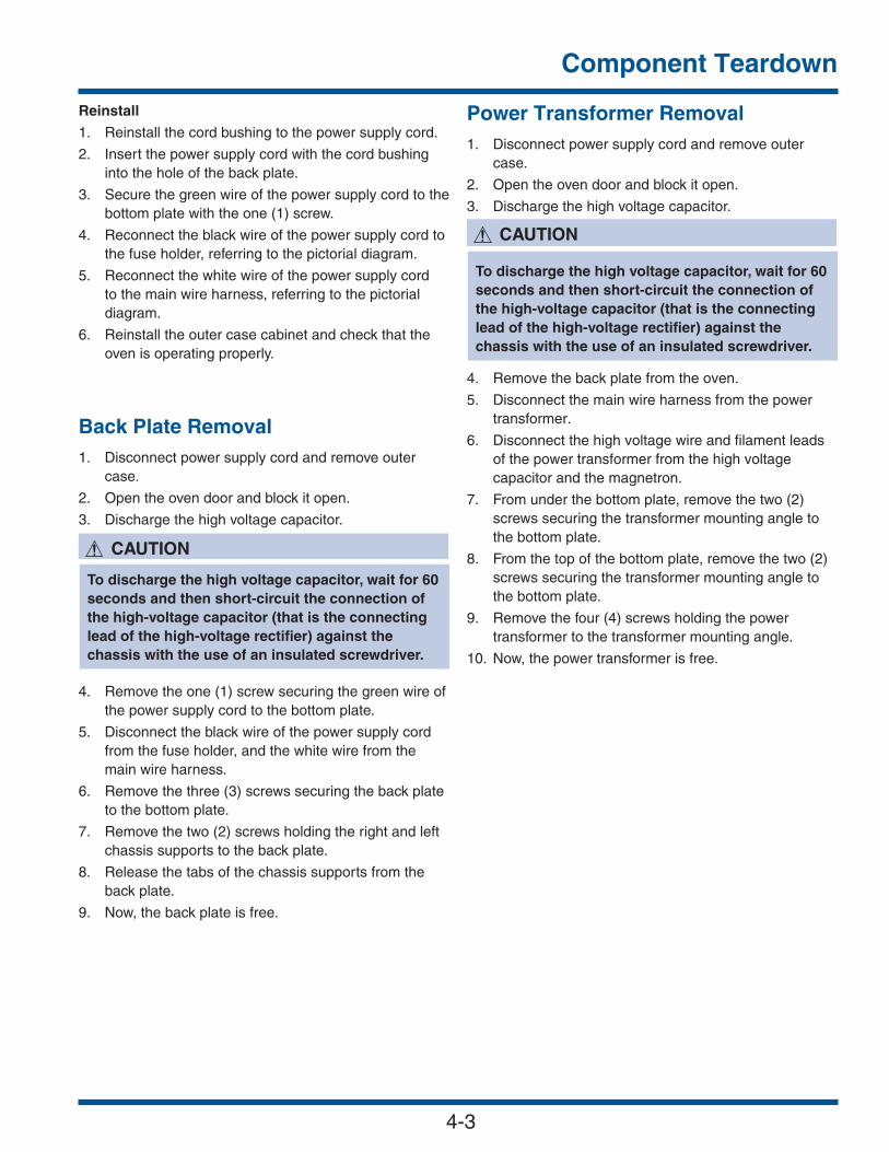
Component Teardown
4-3
Power Transformer Removal1. Disconnect power supply cord and remove outer
case. 2. Open the oven door and block it open.
3. Discharge the high voltage capacitor.
4. Remove the back plate from the oven.
5. Disconnect the main wire harness from the power transformer.
6. Disconnect the high voltage wire and filament leads of the power transformer from the high voltage capacitor and the magnetron.
7. From under the bottom plate, remove the two (2) screws securing the transformer mounting angle to the bottom plate.
8. From the top of the bottom plate, remove the two (2) screws securing the transformer mounting angle to the bottom plate.
9. Remove the four (4) screws holding the power transformer to the transformer mounting angle.
10. Now, the power transformer is free.
To discharge the high voltage capacitor, wait for 60 seconds and then short-circuit the connection of the high-voltage capacitor (that is the connecting lead of the high-voltage rectifier) against the chassis with the use of an insulated screwdriver.
Reinstall
1. Reinstall the cord bushing to the power supply cord.
2. Insert the power supply cord with the cord bushing into the hole of the back plate.
3. Secure the green wire of the power supply cord to the bottom plate with the one (1) screw.
4. Reconnect the black wire of the power supply cord to the fuse holder, referring to the pictorial diagram.
5. Reconnect the white wire of the power supply cord to the main wire harness, referring to the pictorial diagram.
6. Reinstall the outer case cabinet and check that the oven is operating properly.
Back Plate Removal1. Disconnect power supply cord and remove outer
case. 2. Open the oven door and block it open.
3. Discharge the high voltage capacitor.
4. Remove the one (1) screw securing the green wire of the power supply cord to the bottom plate.
5. Disconnect the black wire of the power supply cord from the fuse holder, and the white wire from the main wire harness.
6. Remove the three (3) screws securing the back plate to the bottom plate.
7. Remove the two (2) screws holding the right and left chassis supports to the back plate.
8. Release the tabs of the chassis supports from the back plate.
9. Now, the back plate is free.
To discharge the high voltage capacitor, wait for 60 seconds and then short-circuit the connection of the high-voltage capacitor (that is the connecting lead of the high-voltage rectifier) against the chassis with the use of an insulated screwdriver.

Component Teardown
4-4
High Voltage Capacitor And High Voltage Rectifier Assembly Removal1. Disconnect the oven power supply cord and remove
outer case.
2. Open the oven door and block it open.
3. Discharge high voltage capacitor.
4. Remove the back plate from the oven.
5. Disconnect the high voltage wire of the high voltage rectifier assembly from the magnetron.
6. Disconnect the high voltage wire and the filament lead of the power transformer from the high voltage capacitor.
7. Remove the one (1) screw securing the capacitor holder to the fan motor mounting angle.
8. Remove the one (1) screw holding the high voltage rectifier assembly to the capacitor holder.
9. Disconnect the high voltage rectifier assembly from the high voltage capacitor.
10. Now, the high voltage rectifier assembly is free, and also the high voltage capacitor is free.
When replacing the silicon rectifier assembly, the ground side terminal must be secured firmly with a grounding screw.
To discharge the high voltage capacitor, wait for 60 seconds and then short-circuit the connection of the high-voltage capacitor (that is the connecting lead of the high-voltage rectifier) against the chassis with the use of an insulated screwdriver.
Magnetron Removal1. Disconnect power supply cord and remove outer
case. 2. Open the oven door and block it open.
3. Discharge the high voltage capacitor.
4. Remove the back plate from the oven.
5. Disconnect the high voltage wire of the high voltage rectifier assembly from the magnetron.
6. Disconnect the filament wire of the power transformer from the magnetron.
7. Remove the two (2) screws securing the magnetron guide to the magnetron and remove it.
8. Disconnect the wire leads and the connector from the solid-state relay.
9. Release the main wire harness from the hole of the magnetron separator and the hook of the fan motor.
10. Remove the three (3) screws securing the magnetron separator to the bottom plate and the thermal cover back.
11. Remove the magnetron separator from the oven.
12. Carefully remove the four (4) screws securing the magnetron to the waveguide. When removing the
screws, hold the magnetron to prevent it from falling.
13. Remove the magnetron from the unit with care so the magnetron tube should not be hit by any metal object around the tube.
When replacing the magnetron, be sure the R.F. Gasket is in place and mounting screws are tightened securely.
To discharge the high voltage capacitor, wait for 60 seconds and then short-circuit the connection of the high-voltage capacitor (that is the connecting lead of the high-voltage rectifier) against the chassis with the use of an insulated screwdriver.
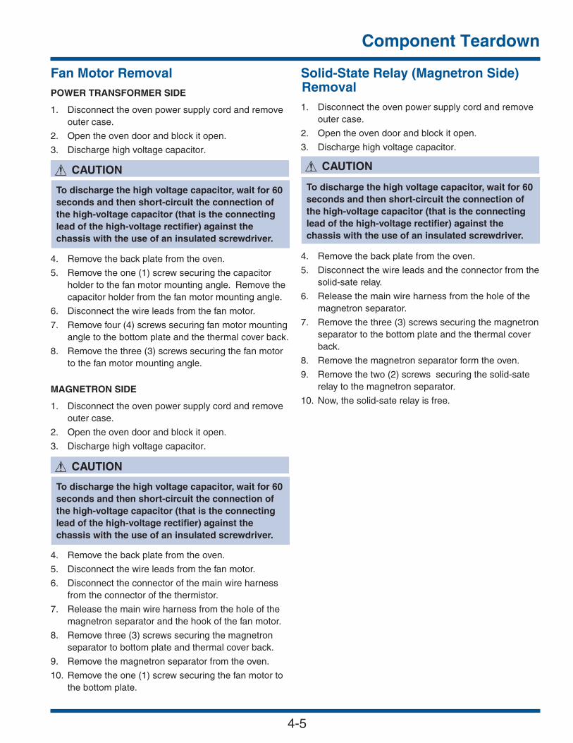
Component Teardown
4-5
Solid-State Relay (Magnetron Side) Removal1. Disconnect the oven power supply cord and remove
outer case.
2. Open the oven door and block it open.
3. Discharge high voltage capacitor.
4. Remove the back plate from the oven.
5. Disconnect the wire leads and the connector from the solid-sate relay.
6. Release the main wire harness from the hole of the magnetron separator.
7. Remove the three (3) screws securing the magnetron separator to the bottom plate and the thermal cover back.
8. Remove the magnetron separator form the oven.
9. Remove the two (2) screws securing the solid-sate relay to the magnetron separator.
10. Now, the solid-sate relay is free.
Fan Motor RemovalPOWER TRANSFORMER SIDE
1. Disconnect the oven power supply cord and remove outer case.
2. Open the oven door and block it open.
3. Discharge high voltage capacitor.
4. Remove the back plate from the oven.
5. Remove the one (1) screw securing the capacitor holder to the fan motor mounting angle. Remove the capacitor holder from the fan motor mounting angle.
6. Disconnect the wire leads from the fan motor.
7. Remove four (4) screws securing fan motor mounting angle to the bottom plate and the thermal cover back.
8. Remove the three (3) screws securing the fan motor to the fan motor mounting angle.
MAGNETRON SIDE
1. Disconnect the oven power supply cord and remove outer case.
2. Open the oven door and block it open.
3. Discharge high voltage capacitor.
4. Remove the back plate from the oven.
5. Disconnect the wire leads from the fan motor.
6. Disconnect the connector of the main wire harness from the connector of the thermistor.
7. Release the main wire harness from the hole of the magnetron separator and the hook of the fan motor.
8. Remove three (3) screws securing the magnetron separator to bottom plate and thermal cover back.
9. Remove the magnetron separator from the oven.
10. Remove the one (1) screw securing the fan motor to the bottom plate.
To discharge the high voltage capacitor, wait for 60 seconds and then short-circuit the connection of the high-voltage capacitor (that is the connecting lead of the high-voltage rectifier) against the chassis with the use of an insulated screwdriver.
To discharge the high voltage capacitor, wait for 60 seconds and then short-circuit the connection of the high-voltage capacitor (that is the connecting lead of the high-voltage rectifier) against the chassis with the use of an insulated screwdriver.
To discharge the high voltage capacitor, wait for 60 seconds and then short-circuit the connection of the high-voltage capacitor (that is the connecting lead of the high-voltage rectifier) against the chassis with the use of an insulated screwdriver.

Component Teardown
4-6
Damper Motor And Damper Switch Removal 1. Disconnect power supply cord and remove outer
case. 2. Open the oven door and block it open.
3. Discharge the high voltage capacitor.
4. Remove the back plate from the oven.
5. Remove the one (1) screw securing the right chassis support to the oven cavity front plate.
6. Disconnect the wire leads from the damper motor.
7. Remove the two (2) screws securing the damper motor to the motor mounting angle.
8. Now, the damper motor is free.
9. Disconnect the wire leads from the damper switch.
10. Remove the two (2) screws securing the motor mounting angle to the damper duct assembly.
11. Remove the one (1) screw securing the damper switch to the motor mounting angle.
12. Now, the damper switch is free.
To discharge the high voltage capacitor, wait for 60 seconds and then short-circuit the connection of the high-voltage capacitor (that is the connecting lead of the high-voltage rectifier) against the chassis with the use of an insulated screwdriver.
Heater Duct Left Assembly, Heater Duct Upper Assembly And Convection Duct Assembly Removal 1. Disconnect power supply cord and remove outer
case. 2. Open the oven door and block it open.
3. Discharge the high voltage capacitor.
4. Remove the back plate from the oven.
5. Remove the door assembly from the oven, referring to “DOOR REPLACEMENT”, and remove the door springs, the door cam right and the door cam left.
6. Remove the power transformer, magnetron, magnetron separator, high voltage capacitor assembly, fan motor (power transformer side) with fan mounting angle, and fan motor (magnetron side), referring to their removal procedures.
7. Disconnect the wire leads from all electrical parts except for the turntable motor, monitor switch, secondary interlock switch and door sensing switch.
8. Remove the two (2) screws securing the latch hook right and latch hook left from the oven cavity front plate.
9. Remove the two (2) screws securing the right and left chassis supports to the oven cavity front plate.
10. Remove the two (2) screws securing the exhaust duct to the oven cavity and remove from unit.
11. Remove the one (1) screw securing the damper duct assembly to the oven cavity from inside of the oven cavity.
12. Remove the two (2) screws securing the damper duct assembly to the thermal cover upper and the wave-
guide.
13. Remove the damper duct assembly from the oven.
14. Remove the two (2) screws securing the separator left to the thermal cover upper and remove from unit.
15. Disconnect the connector of the touch control transformer from the power unit.
16. Remove the one (1) screw securing the touch control transformer to the bottom plate and remove from unit.
To discharge the high voltage capacitor, wait for 60 seconds and then short-circuit the connection of the high-voltage capacitor (that is the connecting lead of the high-voltage rectifier) against the chassis with the use of an insulated screwdriver.

Component Teardown
4-7
Side Heating Element Removal1. Disconnect power supply cord and remove outer
case. 2. Open the oven door and block it open.
3. Discharge the high voltage capacitor.
4. Remove the back plate from the oven.
5. Remove the heater duct left assembly from the oven.
6. Remove one (1) screw securing the heater mounting angle A to the heater duct upper.
7. Remove the two (2) nuts securing the top heating element to the heater duct upper.
8. Now, the top heating element is free.
Turntable Motor Removal1. Disconnect the power supply cord.
2. Wait for 60 seconds to discharge the high voltage capacitor.
3. Remove the turntable tray and the turntable support from the oven cavity.
4. Lay the oven on its backside.
5. Remove the turntable motor cover by snipping off the material in four corners. 6. Where the corners have been snipped off, bend
corner areas flat. No sharp edges must be evident after removal of the turntable motor.
7. Disconnect the wire leads from the turntable motor.
8. Remove the one (1) screw securing the turntable motor to the oven cavity bottom plate.
9. Now, the turntable motor is free.
10. After replacement, use the one (1) screw to fit the turntable motor cover.
To discharge the high voltage capacitor, wait for 60 seconds and then short-circuit the connection of the high-voltage capacitor (that is the connecting lead of the high-voltage rectifier) against the chassis with the use of an insulated screwdriver.
18. Remove the two (2) screws securing the PWB mounting angle to the bottom plate.
19. Remove the PWB mounting angle with the power unit from the bottom plate.
20. Remove the three (3) screws securing the thermal cover left to the heater duct left.
21. Remove the one (1) screw securing the thermal cover left to the thermal cover upper.
22. Straighten the three (3) tabs holding the thermal cover left to the oven cavity, and remove the thermal cover left and the thermal insulation left from the oven cavity.
23. Remove the two (2) screws securing the thermal cover upper to the heater duct upper.
24. Straighten the four (4) tabs holding the thermal cover upper to the oven cavity, and remove the thermal
cover upper and the thermal insulation upper from the oven cavity.
25. Straighten the two (2) tabs holding the thermal insulation upper, and remove it.
26. Remove the fourteen (14) screws securing the heater duct left to the oven cavity and the convection duct.
27. Remove the heater duct left assembly from the oven cavity.
28. Now, the heater duct left assembly is free.
29. Remove the two (2) screws securing the convection motor mounting angle to the bottom plate from under the bottom plate.
30. Remove the thirteen (13) screws securing the convection duct to the oven cavity and the heater duct upper.
31. Remove the convection duct assembly from the oven cavity.
32. Now, the convection duct assembly is free.
33. Remove the nine (9) screws securing the heater duct upper to the oven cavity.
34. Remove the heater duct upper from the oven cavity.
35. Now, the heater duct upper assembly is free.

Component Teardown
4-8
Door Sensing Switch, SecondaryInterlock Switch And Monitor Switch Adjustment
If the door sensing switch, primary interlock switch, thirdinterlock switch and monitor switch do not operate properly due to a misadjustment, the following adjustment should be made.
1. Disconnect the oven power supply cord and remove outer case.
2. Open the oven door and block it open.
3. Discharge the high voltage capacitor.
4. Loosen each screw securing the latch hook right and the latch hook left to the oven cavity front plate.
5. With door closed, adjust the latch hook right and the latch hook left by moving them back and forth and up and down. In and out play of the door allowed by
the latch hook right and the latch hook left should be less than 0.5 mm. The vertical position of the latch hook right and the latch hook left should be adjusted so that the door sensing switch and the primary interlock switch are activated with the door closed. The horizontal position of the latch hook right and the latch hook left should be adjusted so that the plunger of the monitor switch is pressed with the door closed.
Door Sensing Switch, Secondary Interlock Switch and Monitor Switch ReplacementREMOVAL
1. Disconnect the oven power supply cord and remove outer case.
2. Open the door and block it open.
3. Discharge high voltage capacitor.
4. Disconnect the wire leads from the switch.
5. Remove the one (1) screw securing the latch hook (right or left) to the oven cavity front plate, and
release the latch hook (right or left).
6. Keep pushing stopper tab holding switch to the latch hook (right or left) and revolve the switch on the pole.
7. Remove the switch from the latch hook (right or left).
REINSTALL
1. Re-install each switch in its place. The door sensing switch is in the lower position of the latch hook right. The secondary interlock switch is in the lower position of the latch hook left. The monitor switch is in the upper position of the latch hook left.
2. Hold the latch hook (right or left) to the oven cavity front plate and secure with the one (1) screw.
3. Reconnect the wire leads to the switch.
4. Make sure that monitor switch is operating properly and check continuity of the monitor circuit.
To discharge the high voltage capacitor, wait for 60 seconds and then short-circuit the connection of the high-voltage capacitor (that is the connecting lead of the high-voltage rectifier) against the chassis with the use of an insulated screwdriver.
To discharge the high voltage capacitor, wait for 60 seconds and then short-circuit the connection of the high-voltage capacitor (that is the connecting lead of the high-voltage rectifier) against the chassis with the use of an insulated screwdriver.
Monitor Switch
Latch Hook Left
SecondaryInterlock Switch
Pole
PoleStopper
DoorSensing Switch
Latch Hook Right
Pole
Stopper Tab
Tab
Figure 4-3. Switch Removal

Component Teardown
4-9
Monitor Switch
Latch Hook Left
Latch Head
SecondaryInterlock Switch
DoorSensing
Latch Hook Right
Latch Head
Switch
6. Secure the screws firmly.
7. Check all of the switches operation. If any switch has not activated with the door closed, loosen the screws and adjust the position of the latch hook right and the latch hook left.
After adjustment, check the following.
1. In and out play of door remains less than 0.5mm when in the latched position. First check position of latch hook right, pushing and pulling right portion of door toward the oven face. Then check position of the latch hook left, pushing and pulling left portion of the door toward the oven face. Both results (play in the door) should be less than 0.5mm.
2. The door sensing switch, and secondary interlock switch interrupt the circuit before the door can be opened.
3. The monitor switch contacts close when the door is opened.
4. Reinstall the outer case cabinet and check for microwave leakage around the door with an approved microwave survey meter. (Refer to Microwave Measurement Procedure.)
Figure 4-4. Door Switch Components
Door Replacement And AdjustmentDOOR ASSEMBLY REMOVAL
1. Disconnect the oven power supply cord and remove outer case.
2. Open the door and block it open.
3. Discharge high voltage capacitor.
4. Close the door.
5. Remove the two (2) door springs from the door cam right, oven hinge right, door com left and oven hinge left.
6. Release the door cams right and left from the right and left door cam pins of the door.
7. Remove the door cams right and left from the oven cavity front plate.
8. Open the door assembly at an angle of more than 90½ degrees to the oven cavity front plate.
9. To release right and left door hinge pins of the door assembly from the oven hinges right and left, slide door assembly leftward. When removing the door assembly, hold door assembly to prevent damage.
DOOR ASSEMBLY REINSTALLATION
1. On reinstalling the door assembly, insert oven hinges right and left into the right and left door hinge pins.
2. Insert and hook the door cams right and left to the right and left door cam pins.
3. Reinstall the two (2) door springs between the door cams and the oven hinges right and left.
To discharge the high voltage capacitor, wait for 60 seconds and then short-circuit the connection of the high-voltage capacitor (that is the connecting lead of the high-voltage rectifier) against the chassis with the use of an insulated screwdriver.
When the individual parts are replaced, refer to “Door Disassembly”
After any service to the door:
(A) Make sure that the door sensing switch and the secondary interlock switch are operating properly.
(Refer to chapter “Test Procedures”.)(B) An approved microwave survey meter should be
used to assure compliance with proper microwave radiation emission limitation standards.

Component Teardown
4-10
Door Cam Left
Door Assembly
Door Spring
Door Spring
Oven hinge Left
Oven Hinge Right
Door Cam Right
Figure 4-5. Door Replacement and Adjustment
Door Cam Left
Door Assembly
Oven Hinge Left
Oven Hinge Right
Door Cam Right
Left Door Cam Pin
Right Door Cam Pin
Left Door Hinge Pin
Right Door Hinge Pin
Figure 4-6. Door Assembly Components
The door on a microwave oven is designed to actas an electronic seal preventing the leakage ofmicrowave energy from the oven cavity during thecook cycle. This function does not require that thedoor be airtight, moisture (condensation)-tightor light-tight. Therefore, occasional appearanceof moisture, light or sensing of gentle warm airmovement around the oven door is not abnormaland do not of themselves indicate a leakage ofmicrowave energy from the oven cavity. If suchwere the case, the oven could not be equippedwith a vent, the very purpose of which is to exhaustthe vapor-laden air from the oven cavity.
Door AdjustmentWhen removing and/or loosening the oven hinges such as in door replacement, the following adjustment criteria are taken.
Door adjustment is performed with the door properly installed and closed and while the oven hinges are loose.
1. Loosen screws holding the oven hinge right and the oven hinge left to the bottom plate with screwdriver.
2. Adjust door by moving it so that the door is parallel with the oven cavity front plate lines (right and left
side lines) and the door latch heads pass through the latch holes correctly.
3. Tighten the screws holding the oven hinge right and the oven hinge left to the bottom plate.
After adjustment, make sure of the following:
1. The door latch heads smoothly catch the latch hooks through latch holes and the latch heads goes through center of latch holes.
2. The door is positioned with its face pressed toward oven cavity front plate.
3. Reinstall outer case cabinet and check for microwave leakage around the door with an approved microwave survey meter. (Refer to Microwave Measurement Procedure.)

Component Teardown
4-11
Door Disassembly 1. Disconnect the power supply cord and remove outer
case. 2. Open the door and block it open.3. Discharge high voltage capacitor.
4. Remove the door assembly, referring to “Door Replacement”.5. Place the door assembly on a soft cloth with latch
heads facing up.
6. Replacement of the door components are as follows:
CHOKE COVER
7. Insert a putty knife (thickness of about 0.5 mm) into gap between choke cover and door panel assembly.
8. Lift up the choke cover.
9. Now, the choke cover is free from the door panel assembly.
DOOR HANDLE ASSEMBLY
10. Remove the two (2) screws securing the door handle assembly to the door panel assembly through the
door frame.
DOOR PANEL ASSEMBLY, LATCH HEAD RIGHT ANDLATCH HEAD LEFT
11. Remove the fourteen (14) screws securing the door panel assembly to the door frame.
12. Remove door panel assembly from door frame.
ChokeCover
DoorFrame
Door Panel Assembly
Putty Knife
Figure 4-7. Door Disassembly
To discharge the high voltage capacitor, wait for 60 seconds and then short-circuit the connection of the high-voltage capacitor (that is the connecting lead of the high-voltage rectifier) against the chassis with the use of an insulated screwdriver.
As the engaging part of choke cover and door frame are provided at 16 places, do not force any particular part.
When carrying out any repair to the door, do notbend or wrap the slit choke (tabs on the doorpanel assembly) to prevent microwave leakage.
13. Remove the one (1) screw securing the latch head R to the door panel assembly.
14. Remove the latch spring R from the latch head R and the handle lever.
15. Now, the latch head R is free.
16. Remove the one (1) screw securing the latch head L to the door panel assembly.
17. Remove the latch spring L from the latch head L and the handle lever.
18. Now, the latch head L is free.
19. Release the two (2) handle springs from the two (2) handle levers.
20. Pull out the two (2) handle pins from the two (2) handle levers.
21. Remove the two (2) handle levers from the door panel.
MIDDLE DOOR GLASS
22. Remove the two (2) screws securing the glass mounting angle B to the door frame.
23. Remove the middle door glass from the door frame.
FRONT DOOR GLASS
24. Remove each two (2) screws securing the two glass mounting angles A to the door frame.
25. Remove the two (2) glass mounting angles A from the door frame.
26. To release the two (2) tabs securing the lower end of the front door glass, slide the front door glass upward.
27. Release the three (3) tabs securing the upper end of the front door glass and remove the front door glass from the door frame.

Component Teardown
4-12
Servicing The Touch Control PanelPrecautions For Handling Electronic Components
This unit uses CMOS LSI in the integral part of thecircuits. When handling these parts, the followingprecautions should be strictly followed. CMOS LSI haveextremely high impedance at its input and outputterminals. For this reason, it is easily influenced by thesurrounding high voltage power source, static electricitycharge in clothes, etc. and sometimes it is not fullyprotected by the built-in protection circuit.
In order to protect CMOS LSI.
1. When storing and transporting, thoroughly wrap them in aluminium foil. Also wrap all PW boards in aluminium foil.
2. When soldering, ground the technician and use a grounded soldering iron and work table.
Servicing of Touch Control Panel
The following are procedures to permit servicing of thetouch control panel of the microwave oven and theprecautions you must take when doing so. To performthe servicing, power to the touch control panel isavailable either from the power line of the oven itself orfrom an external power source.
A. Servicing the touch control panel with power supply of the oven:
Therefore, before checking the performance of the touchcontrol panel:
1. Disconnect the power supply cord and then remove the outer case.2. Open the door and block it open.3. Discharge high voltage capacitor.4. Disconnect leads to the primary of power transformer.5. Ensure leads remain isolated from other components
and oven chassis by using insulation tape.6. Re-connect the power supply cord.
After checking performance of the touch control panel:
1. Disconnect the power supply cord.2. Open the door and block it open.3. Reconnect leads to the primary of power transformer.4. Reinstall the outer case (cabinet).5. Reconnect the power supply cord after the outer case is installed.6. Run the oven and check all functions. a) On some models, the power supply cord between the touch control panel and the oven itself is so short that the two can’t be separated. For those
models, check and repair all the controls (sensor related ones included) of the touch control panel
while keeping it connected to the oven.
b) On some models, the power supply cord between the touch control panel and the oven proper is long enough that they may be separated from each other. For those models, it is possible to check and repair the controls of the touch control panel while keeping it apart from the oven proper; in this case you must short both ends of the door sensing switch (on PWB) of the touch control panel with a jumper, which activates an operational state that is equivalent to the oven door being closed. As for the sensor-related controls of the touch control panel, checking them is possible if dummy resistor(s) with resistance equal to that of the controls are used.
B. Servicing the touch control panel with powersupply from an external power source:
Disconnect the touch control panel completely from theoven proper, and short both ends of the door sensingswitch (on PWB) of the touch control panel, which bringsabout an operational state that is equivalent to the ovendoor being closed. Connect an external power source tothe power input terminal of the touch control panel, thenit is possible to check and repair the controls of the touchcontrol panel; it is also possible to check the sensorrelated controls of the touch control panel by using thedummy resistor(s).
Servicing Tools
Tools required to service touch control panel assembly.1. Soldering iron: 30W (It is recommended to use a soldering iron with a grounding terminal.)2. Oscilloscope: Single beam, frequency range: DC - 10MHz type or more advanced model.3. Others: Hand tools
Other Precautions
1. Before turning on power source of the control unit, remove the aluminium foil applied for preventing static electricity.2. Connect the connectors of the key unit to the control unit, being sure that the lead wires are not twisted.3. After aluminium foil is removed, be careful that abnormal voltage due to static electricity etc. is not applied to the input or output terminals.4. Attach connectors, electrolytic capacitors, etc. to PWB, making sure that all connections are tight.5. Be sure to use specified components where high precision is required.

Component Teardown
4-13
Control Assembly And CPU UnitRemovalCONTROL PANEL ASSEMBLY
1. Disconnect the oven power supply cord and remove outer case.
2. Open the oven door and block it open.
3. Discharge the high voltage capacitor.
4. Disconnect the 9-pin & 14-pin harness from the connectors CN-J and CN-H on the power unit.
5. Remove the four (4) screws securing the control panel assembly to the oven cavity front plate.
6. Insert a flat edge screwdriver or similar object to release the Locking Tabs on bottom of Panel angle (See Figure 4-9).
7. Slide the control panel assembly leftward to release the eight (6) tabs of the control panel assembly from the oven cavity front plate.
CPU UNIT
8. Disconnect the 14-pin (CNK), 9-pin (CNL) & 10-pin (CNM) harness from the connectors and CN-J and
CN-H on the power unit.
9. Remove the eight (8) screws securing the CPU unit to the panel sub assembly. (See Figure 4-9).
10. Now, the CPU unit is free.
To discharge the high voltage capacitor, wait for 60 seconds and then short-circuit the connection of the high-voltage capacitor (that is the connecting lead of the high-voltage rectifier) against the chassis with the use of an insulated screwdriver.
Tabs
Panel Angle
Panel
Screw
Screw
CPU
Locking tabs
Top
Bottom
Sub Assembly
Figure 4-8. Control Panel and CPU
After the panel angle is removed from the panelsub assembly, it is can be found that the bottomside of the panel sub assembly is melted andtransformed by heat. But it is not abnormal andno problem to use the oven.
Reassembly Note: When reassembling the Control Panel assembly, be sure and lock the (Locking Tabs) back into place to prevent any gaps.

Component Teardown
4-14
Notes

Wiring Diagrams
5-1
SCHEMATICNOTE: CONDITION OF OVEN1. DOOR CLOSED.2. CLOCK APPEARS ON DISPLAY.
LV TT
ran
sfo
rmer
C2C1C4C3
T6T7
T4A
3T2
AA11
D9
RY2
RY1
RY5
RY4
RY3
RY6
1.0 µFAC 2300V
N.O.
N.O.
JM
DM
FM
FM
OL
TTM
COM.
B3
B4
B1
B2B5
B6
D7
D5
D3
E3
E5
E1
D1
240V 60Hz
ORG
BRN
RED
BLK
ORGRED
REDRED
N.O
.C
OM
.
T1T3
" indicates components with potential above 250V.
1. Circuits/ Wire colors subject to change without notice.Notes:
BLK
BLK
BLK
BLK
BLK
BLK
BLKGR
N
GN
D
WH
TW
HT
WH
T
GR
Y
GR
Y
GR
Y
WHT
Fuse
20A
Red
Red
Red
Red
BR
N
BR
N
BR
N
Sid
e Heater
Th
ermal
Cu
t-ou
t
MG
Temp
. Fu
se
Top
Heater
Th
ermal
Cu
t-ou
t
Com. PrimaryInterlock Relay
So
lid-S
tate Relay
So
lid-S
tate Relay
Fu
seF
10A
Co
ntro
l Un
it
Fu
se 12.5A
GR
N
GRN
GR
NB
RN
GR
N
WH
T
BLK
BLK
RED
BLU
REDRED
BLU
BLU
ORG
ORGORG
ORG
ORG
Seco
nd
aryIn
terlock S
witch
BLK
BLK
BLK
RED
RED
RED
Fan Motor
Oven Lamp
Damper Motor
Jet Motor
GRYGRY
GRY
GRY
GRY
WHT
WHTWHT
WHT
WHT
WHTBLU
DamperSwitch
DoorSensingSwitch
Thermistor
RED
RED
BLK
ORG
Magnetron
PowerTransformerWith 150˚C ThermostatIn Primary Winding
Capacitor
Rectifier
Side Heater
Top Heater
Monitor Switch
Turn Table Motor
BLK
BLKGRY
GRY
WHTGRY
GRYGRY
ORG
"2.
Wiring SchematicOven Off Condition

Wiring Diagrams
5-2
PR
EH
EA
T
GR
ILL
RO
AS
T
MIN
PLU
S
TM
R/C
LOC
K
ST
OP
7P
LUS
60
59
32
CO
NV
EC
TR
EC
IPE
SM
INU
S8
41
HE
LPR
EH
EA
T
DE
FR
OS
TS
TA
RT
EN
TE
RP
OP
CO
RN
PW
R L
EV
EL
BA
KE
Bac
klig
ht A
ll B
lue
LED
Backlit LED Diagram

Wiring Diagrams
5-3
PIES
MIN
USPO
ULTR
YDE
SSER
TSHE
LPM
EATS
STAR
T
GRI
LLRO
AST
PREH
EAT
BREA
DS
BAKE
REHE
AT
DEFR
OST
COM
PUCO
OK
PIZZ
AS
BASI
C CO
OK
PWR
LEVE
L
PLUS
STO
P
MIN
PLU
SSN
ACKS
POPC
ORN
RECI
PES
CONV
ECT
ENTE
R
SEAF
OO
DTM
R/CL
OCK
CASS
ERO
LES
Fun
ctio
n LE
D -
All
Blu
e E
xcep
t Sta
rt a
nd C
ance
l
Function LED Diagram

Wiring Diagrams
5-4
TU
RN
TA
BLE
M
OT
OR
LV TR
AN
SF
OR
ME
R
CO
NV
EC
TIO
NM
OT
OR
CA
PA
CIT
OR
RY
1
BLK
GR
N
RE
D
DA
MP
ER
M
OT
OR
FA
N M
OT
OR
(Mag
netr
on s
ide)
PR
IMA
RY
INT
ER
LOC
KR
ELA
Y
TO
P H
EA
TE
RT
HE
RM
AL
CU
T-O
UT
from
C
PU
UN
IT
MA
GN
ET
RO
NT
EM
PE
RA
TU
RE
FU
SE
GR
Y
CN
-T
N.O
.
CO
M
CO
M
CN
-BC
N-T
SE
CO
ND
AR
YIN
TE
RLO
CK
SW
ITC
H
HIG
H V
OLT
AG
E
CO
MP
ON
EN
TS
PO
WE
R U
NIT
SID
EH
EA
TIN
GE
LEM
EN
T
TO
P
HE
AT
ING
ELE
ME
NT M
ON
ITO
RS
WIT
CH
CO
NV
EC
TIO
N
MO
TO
R
TH
ER
MIS
TO
R
SO
LID
-ST
AT
ER
ELA
Y
(Mag
netr
on s
ide)
PO
WE
R S
UP
PLY
CO
RD
240V
60H
zN
OT
E:
The
gro
undi
ng c
ondu
ctor
of
the
pow
er s
uppl
y co
rd h
as
been
gro
unde
d by
pow
er s
uppl
y co
rd fi
scr
ew.
The
scr
ew m
ust b
e ke
pt a
llway
s tig
ht.
OV
EN
LA
MP
N.O
.
FU
SE
F10
A
MA
GN
ET
RO
N
HIG
H V
OLT
AG
EC
AP
AC
ITO
R
HIG
H V
OLT
AG
ER
EC
TIF
IER
PO
WE
R
TR
AN
SF
OR
ME
RB
LK
BLK
WH
T
WH
T
GR
Y
CN-G
CN
-F
RE
D
RE
D
R E D
R E D
R E D
R E D
B L K
B L K
R E D
R E D
B L K
R E D
O R GO R G
B R N
DO
OR
SE
NS
ING
SW
ITC
HG R N
G R NB
RN
RE
D
BLK
GR
N
CO
MN
.C.
BLK
OR
G
RE
D
BLU
RE
D
8 7 6 5 4 3 2 1
BLK BLU
1
1 14
19
6
CN
-E
15
CN
-C
CN
-C
CN
-G
CO
M.
14
1
43
21
7
BLU
BR
N
DA
MP
ER
SW
ITC
HC
OM
N.O
.
GR
Y
GR
Y
WH
T
GR
Y
WH
T
BLK
W H T
G R Y
G R Y
G R Y
O R G
BLK
WHT
1
2
3
4
56
RED
GRN
BLU
BRN
CN
-E
BLK1
2
3
4
5
RED
ORG
CN
-D
BLU
BLK
WH
T
89 7 6 5 4 3 2 1
BR
N
GR
Y
RY
2
CO
M.
GR
Y
BLK
RE
D
RE
DR
ED
WH
T
WH
T
BLK
WH
T
GR
Y
OR
G
OR
G
FA
N M
OT
OR
(Pow
er tr
ansf
orm
er s
ide)
1
1 2
2
34
RE
D
BR
N
BRN
12
3ORG
SO
LID
-ST
AT
ER
ELA
Y
(Sid
e he
atin
gel
emen
t sid
e)
12
34
WH
T
OR
G
OR
G
BR
N
RED
12
3BLK
WH
T
BLK
1 2 3
RE
DW
HT
BLK
RE
D
WH
T
BLU
RE
D
BLK
OR
G
GR
Y
WH
T
GR
Y
SID
EH
EA
TE
RT
HE
RM
AL
CU
T-O
UT
CN
-A1
3
CN-F
CN-D
9 1
WH
TB
LK WH
T
GR
YR
ED
NO
ISE
F
ILT
ER
R E D
BLK
OR
GC
N-B
1
2
3
BLK
BLK
RED
1
2
3
4
5
6
ORG
ORG
BLU
BLU
RED7
CN
-A
CNJCNH
SE
E C
IRC
UIT
SC
HE
MA
TIC
S
CP
U U
NIT
12
11419
1 14
CNL CNM
CNK
to L
ED
& K
EY
BO
AR
DS
TIN
U R
EW
OP
ot)
G-N
C &
F-N
C(
}
Pictorial Diagram

Wiring Diagrams
5-5
Power Unit Circuit

Wiring Diagrams
5-6
CPU Unit Circuit

Wiring Diagrams
5-7
89
10113
4
12
12135
6
HE
LP
CO
NV
EC
T
ST
OP
ST
AR
T
DE
FR
OS
T
943 8
MIN
US
1 6
GR
ILL
BA
KE
PO
PC
OR
NB
AS
IC C
OO
KP
LUS
PR
EH
EA
TC
OO
KR
EC
IPE
S
AD
D M
IN05
72
RO
AS
TR
EH
EA
TE
NT
ER
KE
Y F
UN
CT
ION
Key Function

Wiring Diagrams
5-8
Notes

Parts List
6-1
Note: The parts marked "ΔΔΔΔΔ" may cause undue microwave exposure.The parts marked "*" are used in voltage more than 250V.
123456789
10111213141516
Secondary interlock/door sensing/damper switchDamper motorTop heating elementSide heating elementThermistorConvection motorTurntable motorFan motor assyPower supply cordHigh voltage rectifier assyHigh voltage capacitorMonitor fuse 20A and monitor switch (V-5220Q) assemblySolid-state relayFuse F10ATemperature fuse 150 deg. C (MG)Fuse holder
3111111211112111
171819
Convection motor capacitorOven lampThermal cut out 170ºC(Top heater) 170ºC OFF 155ºC ON
111
2021
Thermal cut out 150ºC(Side heater) 150ºC OFF 130ºC ONPower transformer
11
222324
LV transformerMagnetronNoise filter
111
ELECTRICAL PARTS
REF. NO. DESCRIPTION Q’TY
25262728
29303132
3334
Back plateBottom plateLegOuter case cabinet
Power unit (located on bottom plate)CPU unitKey unitSpecial screw
Damper duct assemblyPWB mounting angleMotor mounting angle
1121
1118
111
CABINET PARTS
37383940414243
Damper cushion Damper
3536 Damper cam
Damper shaft
Catalyst angleHeater mounting angle AHeater duct upperCatalystHeater mounting angle B
11
11
31131
CONTROL PANEL PARTS
44454647484950
Heater duct leftCoupling assemblyExhaust ductConvection fan assemblyConvection motor mounting angleConvection duct
111111
OVEN PARTS
***
*
*Δ

Parts List
6-2
51525354555657585960616263646566
Thermal insulator backThermal cover backDivide plate ADivide plate BOven cavity (Non replaceable part)Turntable mounting angleSeparator leftLamp mounting angleMagnetron separatorCushionCushionThermal insulation LRear separatorThermal insulation UpperThermal insulation BottomLamp glass
1111111111211111
676869
Silcon packingThermal cover UpperThermal cover Left
111
7071
Thermal cover DFan motor mounting angle
11
727374
Capacitor holderOven hinge LeftOven hinge Right
111
OVEN PARTS
REF. NO. DESCRIPTION Q’TY
77787980
838485868788
Top ductTransformer mounting angle
7576
Latch hook RightLatch hook Left
Chassis supportMagnetron guide
8182
Door Cam LeftDoor Cam RightDoor springWaveguide coverCushionVent extrusionCushionCushionBottom duct
11
11
21
21
11
12211
91929394959697
Edge cover Cushion
8990 Cushion
Cushion
CushionCushionCushionCushionCushion
31
12
1111198
99100101
Noise unit angleSide trim RSide trim L
111
102103104105106107108109110111112113114115116
Door assyDoor handleScrewChoke coverHandle adapter leftHandle adapter rightLatch head RightLatch head LeftHandle springHandle leverLatch spring RightLatch spring LeftScrew : 4mm x 8mmScrew : 4mm x 20mmHandle pin
1121111122111222
117118
High rack assemblyLow rack assembly
11
119120
Turntable supportTurntable tray
11
121122123
Splash guardCook bookInstruction book
111
DOOR PARTS
REF. NO. DESCRIPTION Q’TY
126127128129130131132133134135
Thermistor harnessCord bushing
124125
User & care guideMain wire harness
Purse lock LMonitor cautionDHHS caution labelUser caution labelThermal insulatorCord holderPurse lock LLShipping side angle L (Not replaceable)Shipping side angel R (Not replaceable)
11
11
111111111
138139140
French user caution label BIK-height caution label
136137 Back duct
NHW caution label11
11
MISCELLANEOUS

Parts List
6-3
CONTROL PANEL PARTS
31
3032
104
113
109
116
108
112
104
110
116
110
111
115
111
115
114
106
103
105
107
102
131
139
DOOR PARTS
Control and Door Parts
141142143144145146147148149150151152153154155
Nut: 4mm x 3.2mmScrew : 4 mm x 8 mmScrew : 4 mm x 6 mmScrew : 4 mm x 8 mmScrew : 4mm x 8 mmScrew : 4mm x 8 mmScrew : 4mm x 8 mmScrew : 4mm x 12 mmSpecial screw (Torx tamper proof screw)CushionSpecial screwScrewScrew : 4mm x 8mmSpecial screwScrew : 4mm x 12mm
455612436652141371
156157
Special screwScrew : 3 mm x 10 mm
11
158159
Screw : 3 mm x 10 mmSpecial screw
112
160161162
Screw : 4mm x 8mmScrew : 3mm x 14mmClip retainer
212
SCREWS, NUTS, WASHERS AND OTHER
REF. NO. DESCRIPTION Q’TY
165166167168
CushionLamp cover
163164
Anti-tip bracket assySchematic
CushionCushion
11
11
11

Parts List
6-4
Cabinet And Frame Parts
138
37
162
13938
3388
68
91
153
892
153
92
72 93
11
146
153
14215
3
79
145
14510
47
16
14
158
1814
7
153
77
2592
x3
1735
36
148 57
95
148
148
143
161
161
145
2
153
x2
158
5814
314
3
143
40
43
40
53
147
x2
x4
143 x2
x4
143
5x4
x2
158
143
148
158
143
69
45
62
153
87
143
160
44
143
143 15
3
155
4
67
8412
1
143
13 129
20x2
154
64
42
154
153
71
91x2
x4
120
155
143
4043
76
119
145
148
7015
3
27
2761
26
153
153
158
15
9615
3
79
145
73 61
83
83
81
78
143
x3
14515
3
85
153
153
55
152
80
143
153
4814
314
3
143
143
3
41
155
143
54
21
23
7482
145
153
153
153
153
157
65
1
6614
575
160
56
145
746
142
x2
x4
x2
153
60
63
8
146
146
153
342915
915
8x2
x3
x3
153
127
9
153
153
144
6
133
148
90
51
50
144
5298
13
22
5997
89
49
153
19
94
11
63
24 9912
86
86
101
100
135
136
137
140
130
164
148
148
x6
148
x3
148
x3
148
x6
148
x6
x314
8
165
162
162
163
163
148
x2
148
x2
148
28
166
151
167
152
151
168
150
148
148
148
148

Parts List
6-5
MISCELLANEOUS
120 TURNTABLE TRAY
122 COOK BOOK123 INSTRUCTION BOOK124 USE & CARE GUIDE
119 TURNTABLE SUPPORT
TRAY PAD
DOOR PROTECTION SHEET
PLASTIC BAG
TRAY HOLDER
121 SPLASH GUARD
117 HIGH RACK
118 LOW RACK
Not replaceable items.
PACKING CASE
Actual wire harness may be different than illustration.
117
132
128 135
118
121
125
126
POSITION OF PURSE LOCK
128 Pursu lock L
134 Pursu lock LL
Main wire harness
Main wire harness
LVtransformer
20-pin wire harness
Power unit
SIDE CROSS SUPPORTBOTTOM BOX SUPPORT
BOTTOM BASE PAD
TOP BASE PAD
TOP CROSS SUPPORT
VERTICAL CORNER POST
PACKING AND ACCESSORIES
Packing and Accessories

Parts List
6-6
Notes