Technical Section Subdivision surface watermarking · to detect any change in the document. An...
13
Computers & Graphics 31 (2007) 480–492 Technical Section Subdivision surface watermarking Guillaume Lavoue´ , Florence Denis, Florent Dupont LIRIS UMR 5205, INSA-Lyon and Universite´Lyon 1, F-69621, France Received 23 January 2006; received in revised form 31 August 2006; accepted 11 January 2007 Abstract This paper presents a robust non-blind watermarking scheme for subdivision surfaces. The algorithm works in the frequency domain, by modulating spectral coefficients of the subdivision control mesh. The compactness of the watermarking support (a coarse control mesh) has led us to optimize the trade-off between watermarking redundancy (which ensures robustness) and imperceptibility by introducing two contributions: (1) spectral coefficients are perturbed according to a new modulation scheme analysing the spectrum shape and (2) the redundancy is optimized by using error correcting codes coming from telecommunication theory. Since the watermarked surface can be attacked in a subdivided version, we have introduced an algorithm to retrieve the control polyhedron, starting from a subdivided, attacked version. Experiments have shown the high robustness of our scheme against geometry attacks such as noise addition, quantization or non-uniform scaling and also connectivity alterations such as remeshing or simplification. r 2007 Elsevier Ltd. All rights reserved. Keywords: Subdivision surfaces; Digital watermarking; Spectral analysis; Error correcting codes; Surface approximation 1. Introduction Watermarking provides a mechanism for copyright protection or ownership assertion of digital media by embedding information in the data. A watermark is associated with different characteristics, depending on its purpose. For copyright protection, the watermark has to be robust to survive (i.e. remain detectable) through malicious attacks; on the contrary, for applications like integrity verification, the watermark has rather to be fragile to detect any change in the document. An other characteristic of a watermarking algorithm concerns the mark extraction which can be blind (the original document is not required to extract the mark) or non-blind (the original document is needed). The last important attribute of a watermark is the imperceptibility; indeed, the watermarked document has to be visually near identical to the original. More information about digital watermarking can be found in [1]. There still exist few watermarking algorithms for 3D models, moreover, most of the existing methods concern polygonal meshes and ignore other 3D surface representa- tions and particularly subdivision surfaces. A subdivision surface is a smooth surface defined as the limit surface generated by an infinite number of refinement operations using a subdivision rule on an input coarse control mesh. Hence, it can model a smooth surface of arbitrary topology while keeping a compact storage and a simple representa- tion. Subdivision surfaces are now widely used in com- puter graphics and have been integrated to the MPEG4 standard [2]. In this context we present a robust, imperceptible, non- blind watermarking scheme for subdivision surfaces to serve ownership claims. The algorithm is based on a frequency domain decomposition of the subdivision con- trol mesh and on spectral coefficient modulation. In order to adapt our algorithm to the compactness of the cover object (the coarse control mesh), we have optimized the trade-off between watermarking redundancy (which en- sures robustness) and imperceptibility by introducing a new modulation scheme and error correcting codes (ECC). A so-called synchronization process was also introduced to ARTICLE IN PRESS www.elsevier.com/locate/cag 0097-8493/$ - see front matter r 2007 Elsevier Ltd. All rights reserved. doi:10.1016/j.cag.2007.01.022 Corresponding author. Tel.: +33 04 72 44 83 95; fax: +33 04 72 43 15 36. E-mail address: [email protected] (G. Lavoue´ ).
Transcript of Technical Section Subdivision surface watermarking · to detect any change in the document. An...
ARTICLE IN PRESS
0097-8493/$ - se
doi:10.1016/j.ca
�Correspondfax: +3304 72 4
E-mail addr
Computers & Graphics 31 (2007) 480–492
www.elsevier.com/locate/cag
Technical Section
Subdivision surface watermarking
Guillaume Lavoue�, Florence Denis, Florent Dupont
LIRIS UMR 5205, INSA-Lyon and Universite Lyon 1, F-69621, France
Received 23 January 2006; received in revised form 31 August 2006; accepted 11 January 2007
Abstract
This paper presents a robust non-blind watermarking scheme for subdivision surfaces. The algorithm works in the frequency domain,
by modulating spectral coefficients of the subdivision control mesh. The compactness of the watermarking support (a coarse control
mesh) has led us to optimize the trade-off between watermarking redundancy (which ensures robustness) and imperceptibility by
introducing two contributions: (1) spectral coefficients are perturbed according to a new modulation scheme analysing the spectrum
shape and (2) the redundancy is optimized by using error correcting codes coming from telecommunication theory. Since the
watermarked surface can be attacked in a subdivided version, we have introduced an algorithm to retrieve the control polyhedron,
starting from a subdivided, attacked version. Experiments have shown the high robustness of our scheme against geometry attacks such
as noise addition, quantization or non-uniform scaling and also connectivity alterations such as remeshing or simplification.
r 2007 Elsevier Ltd. All rights reserved.
Keywords: Subdivision surfaces; Digital watermarking; Spectral analysis; Error correcting codes; Surface approximation
1. Introduction
Watermarking provides a mechanism for copyrightprotection or ownership assertion of digital media byembedding information in the data. A watermark isassociated with different characteristics, depending on itspurpose. For copyright protection, the watermark has tobe robust to survive (i.e. remain detectable) throughmalicious attacks; on the contrary, for applications likeintegrity verification, the watermark has rather to be fragile
to detect any change in the document. An othercharacteristic of a watermarking algorithm concerns themark extraction which can be blind (the original documentis not required to extract the mark) or non-blind (theoriginal document is needed).
The last important attribute of a watermark is theimperceptibility; indeed, the watermarked document has tobe visually near identical to the original. More informationabout digital watermarking can be found in [1].
e front matter r 2007 Elsevier Ltd. All rights reserved.
g.2007.01.022
ing author. Tel.: +3304 72 44 83 95;
3 15 36.
ess: [email protected] (G. Lavoue).
There still exist few watermarking algorithms for 3Dmodels, moreover, most of the existing methods concernpolygonal meshes and ignore other 3D surface representa-tions and particularly subdivision surfaces. A subdivisionsurface is a smooth surface defined as the limit surfacegenerated by an infinite number of refinement operationsusing a subdivision rule on an input coarse control mesh.Hence, it can model a smooth surface of arbitrary topologywhile keeping a compact storage and a simple representa-tion. Subdivision surfaces are now widely used in com-puter graphics and have been integrated to the MPEG4standard [2].In this context we present a robust, imperceptible, non-
blind watermarking scheme for subdivision surfaces toserve ownership claims. The algorithm is based on afrequency domain decomposition of the subdivision con-trol mesh and on spectral coefficient modulation. In orderto adapt our algorithm to the compactness of the coverobject (the coarse control mesh), we have optimized thetrade-off between watermarking redundancy (which en-sures robustness) and imperceptibility by introducing a newmodulation scheme and error correcting codes (ECC). Aso-called synchronization process was also introduced to
ARTICLE IN PRESSG. Lavoue et al. / Computers & Graphics 31 (2007) 480–492 481
ensure robustness to attacks against a subdivided versionof the surface.
Section 2 presents subdivision surfaces, a state of the artabout 3D watermarking and the overview of our frame-work. Section 3 details our different contributions and thecomplete watermarking algorithm, while Section 4 givessome results and comparisons with existing methods.
2. Context and overview
2.1. Subdivision surface presentation
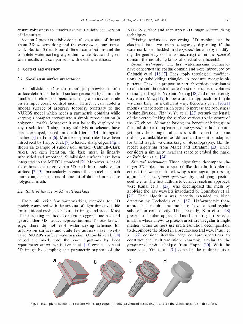
A subdivision surface is a smooth (or piecewise smooth)surface defined as the limit surface generated by an infinitenumber of refinement operations using a subdivision ruleon an input coarse control mesh. Hence, it can model asmooth surface of arbitrary topology (contrary to theNURBS model which needs a parametric domain) whilekeeping a compact storage and a simple representation (apolygonal mesh). Moreover it can be easily displayed toany resolution. Today, many subdivision schemes havebeen developed, based on quadrilateral [3,4], triangularmeshes [5] or both [6]. Moreover special rules have beenintroduced by Hoppe et al. [7] to handle sharp edges. Fig. 1shows an example of subdivision surface (Catmull–Clarkrules). At each iteration, the base mesh is linearlysubdivided and smoothed. Subdivision surfaces have beenintegrated to the MPEG4 standard [2]. Moreover, a lot ofalgorithms exist to convert a 3D mesh into a subdivisionsurface [7–13], particularly because this model is muchmore compact, in terms of amount of data, than a densepolygonal mesh.
2.2. State of the art on 3D watermarking
There still exist few watermarking methods for 3Dmodels compared with the amount of algorithms availablefor traditional media such as audio, image and video. Mostof the existing methods concern polygonal meshes andignore other 3D surface representations. To our knowl-edge, there do not exist watermarking schemes forsubdivision surfaces and quite few authors have investi-gated NURBS surface watermarking: Ohbuchi et al. [14]embed the mark into the knot equations by knotreparameterization, while Lee et al. [15] create a virtual2D image by sampling the parametric support of the
Fig. 1. Example of subdivision surface with sharp edges (in red). (a)
NURBS surface and then apply 2D image watermarkingtechniques.Existing techniques concerning 3D meshes can be
classified into two main categories, depending if thewatermark is embedded in the spatial domain (by modify-ing the geometry or the connectivity) or in the spectral
domain (by modifying kinds of spectral coefficients).Spatial techniques: The first watermarking techniques
have concerned the spatial domain and were introduced byOhbuchi et al. [16,17]. They apply topological modifica-tions by subdividing triangles to produce recognizablepatterns. They also propose to perturb vertices coordinatesto obtain certain desired ratio for some tetrahedra volumesor triangles heights. Yeo and Yeung [18] and more recentlyCayre and Macq [19] follow a similar approach for fragilewatermarking. In a different way, Benedens et al. [20,21]modify surface normals, in order to increase the robustnessto simplification. Finally, Yu et al. [22] perturb the lengthof the vectors linking the surface vertices to the centre ofthe 3D object. Although having the benefit of being quitefast and simple to implement, these spatial methods do notyet provide enough robustness with respect to someordinary attacks like noise addition, and are rather adaptedfor blind fragile watermarking or steganography, like therecent algorithm from Maret and Ebrahimi [23] whichconsiders a similarity invariant space to embed the mark,or Zafeiriou et al. [24].
Spectral techniques: These algorithms decompose thetarget 3D object into a spectral-like domain, in order toembed the watermark following some signal processingapproaches like spread spectrum, by modifying spectralcoefficients. The first authors to consider such an approachwere Kanai et al. [25], who decomposed the mesh byapplying the lazy wavelets introduced by Lounsbery et al.[26]. Their algorithm was recently extended to blinddetection by Uccheddu et al. [27]. Unfortunately theseapproaches require the mesh to have a semi-regularsubdivision connectivity. Thus, recently, Kim et al. [28]present a similar approach based on irregular waveletanalysis which allows to process arbitrary irregular trianglemeshes. Other authors use multiresolution decompositionto decompose the object in a pseudo-spectral way. Praun etal. [29] consider iterative edge collapse operations toconstruct the multiresolution hierarchy, similar to theprogressive mesh technique from Hoppe [30]. With thesame idea, Yin et al. [31] consider the multiresolution
Control mesh, (b,c) 1 and 2 subdivision steps, (d) limit surface.

ARTICLE IN PRESS
Fig. 2. Our subdivision surface watermarking framework. (a) Watermark
embedding, (b) Watermark extraction.
G. Lavoue et al. / Computers & Graphics 31 (2007) 480–492482
decomposition scheme from Guskov et al. [32]. Finally,Ohbuchi et al. [33,34] employ the spectral mesh analysisproposed by Karni and Gotsman [35]. The mesh isdecomposed on the eigenvectors of its Laplacian matrix,which reflect a real spectral decomposition, particularlyadapted for watermarking. Unfortunately this decomposi-tion requires a high computation time, which has led theauthors to cut the input mesh into several parts beforeprocessing. Thus, Wu and Kobbelt [36] have introduced anew set of orthogonal basis functions derived from radialbasis functions, allowing to process large meshes. Finally,Li et al. [37] map the input mesh into a sphere (sphericalparameterization) and then apply the spherical harmonictransform which provides a kind of Fourier frequencyrepresentation of the mesh. Although some blind algo-rithms exist in these spectral domains [38], most of thespectral techniques presented in this paragraph are additiveand not blind, besides the watermarks are mostlyembedded in the low frequencies [29,31,34,36], in order tominimize the visual distortion and also to remain robust tohigh-frequency perturbations like noise addition orsmoothing. These spectral algorithms are particularlyrobust to a large variety of attacks such as noise addition,cropping, filtering, simplification, resampling andsimilarities.
2.3. Objective and framework
Our objective is to propose an efficient watermarkingalgorithm for subdivision surfaces, which have not been,for the moment, considered in existing 3D techniques, inspite of their popularity and widespread use. Basically,every existing polygonal mesh watermarking techniquecould be applied on subdivision surfaces since correspond-ing control polyhedrons are polygonal meshes. However,these surfaces have two specificities which cannot beignored to design a real efficient applicable watermarkingscheme:
(1)
For a given 3D shape, this representation is much morecompact than a polygonal mesh, since the subdivisioncontrol polyhedron contains much fewer vertices. Thusthere is much less available space to embed thewatermark.(2)
Concerning the possible attacks against the water-marked subdivision surface, they can occur on twodifferent states: against the control polyhedron oragainst a subdivided version.Taking into account these characteristics, our frameworkfor subdivision surface watermarking, detailed in Fig. 2, isthe following:
Our principal objective is the robustness of the mark,thus we have chosen a spectral domain to embed thewatermark; among existing decomposition schemes, thespectral analysis from Karni and Gotsman [35] leads to thebest decorrelation really close to a theoretical Fourier
analysis (see Section 3.1). The fact that this decompositionscheme is heavy in calculation is not a problem in our casesince we apply it on subdivision control polyhedrons. Thecompactness of the watermarking support (a coarse controlpolyhedron) has led us to optimize the efficiency of theinsertion in two different ways:
�
We propose an extension of the simple additive water-marking scheme, used by most of the authors andparticularly by Ohbuchi et al. [33,34], by increasingembedding strength on low-frequency components, inwhich alterations are less visible for human eyes (seeSection 3.2). At the opposite to most of the existingmethods, our algorithm will also watermark some high-frequency components, since disturbing a high-fre-quency of a subdivision control polyhedron has finallya low-frequency impact on the limit surface andtherefore leads to low visual distortions. � In [33,34], the mark is repeated several times to increasethe robustness; at the extraction, the extracted marks areaveraged to calculate the correlation. We have investi-gated a more sophisticated technique, coming fromtelecommunication theory, to increase the robustness ofour mark using convolutional encoding (see Section 3.3).
Our extraction process needs to compare the watermarkedsubdivision control polyhedron with the original one.However, attacks can occur on a subdivided version ofthe watermarked surface. Thus, we propose an algorithmto retrieve the control polyhedron, starting from asubdivided, attacked (by noise addition, remeshing, sim-plification) version: the control mesh synchronization (seeSection 3.4).
3. Subdivision surface watermarking algorithm
3.1. Spectral analysis
The mesh spectrum is obtained by projecting the vertexcoordinates on the eigenvalues of the Laplacian matrix of

ARTICLE IN PRESS
Fig. 3. Amplitude spectrum of the 3D object SubRabbit and evolution of
the watermarking strength (b function) according to parameter T .
G. Lavoue et al. / Computers & Graphics 31 (2007) 480–492 483
the input polygonal mesh. Karni and Gotsman [35] andBollabas [39] propose two distinct definitions for thecomputation of such a matrix. We consider Bollabas’sone, which leads to an easier eigenvalues decomposition.The Laplacian matrix L is defined by
L ¼ D� A, (1)
where D is a diagonal matrix whose each diagonal elementdii corresponds to the valence of the vertex i (the valence isequal to the number of edges connected to this vertex) andA is the adjacency matrix of the mesh whose each elementaij is defined by
aij ¼1 if vertices i and j are adjacent;
0 otherwise:
�(2)
For a mesh with n vertices, matrices A, D and L have ann� n size. The eigenvalues decomposition of the Laplacianmatrix L gives n eigenvalues li and n eigenvectors wi. Bysorting the eigenvalues in an ascending order, the n
corresponding eigenvectors form a set of basis functionswith increasing frequencies, only depending on the meshconnectivity (geometry is not taken into account). We callW the n� n projection matrix constructed with thejuxtaposition of the n ordered column eigenvectors.
The geometry information of the mesh, containing n
vertices vi ¼ ðxi; yi; ziÞ, can be represented by three vectorsX, Y and Z:
X ¼ ðx1;x2; . . . ;xnÞ,
Y ¼ ðy1; y2; . . . ; ynÞ,
Z ¼ ðz1; z2; . . . ; znÞ. ð3Þ
The spectral decomposition is obtained by projecting thesethree vectors on the eigenvector basis and produces threespectral coefficient vectors P, Q and R. These orderedcoefficient vectors form three mesh spectra correspondingto the three orthogonal coordinate axes in the spectraldomain:
P ¼W :X ;
Q ¼W :Y ;
R ¼W :Z:
8><>: (4)
The geometry can be retrieved using spectral coordinatesand inverse matrix W�1:
X ¼W�1:P;
Y ¼W�1:Q;
Z ¼W�1:R:
8><>: (5)
The amplitude spectrum can be obtained by computingcoefficients si for each vertex by using the transformedcoordinates ðpi; qi; riÞ with the following equation:
si ¼
ffiffiffiffiffiffiffiffiffiffiffiffiffiffiffiffiffiffiffiffiffiffiffiffiffiffiffiffiðp2
i þ q2i þ r2i Þ
q. (6)
Fig. 3 presents the amplitude spectrum obtained for theSubRabbit model (200 vertices) which shows a very fastdecrease, since most of the geometric information is
concentrated in low frequencies. We have not representedthe first coefficient which corresponds to the continuouscomponent (i.e. the position) of the object and is notconsidered in the watermarking process.
3.2. Spectral coefficient modulation
Our watermarking algorithm embeds the marks byperturbing the amplitude of the coefficients of the meshspectra P, Q and R, following the spread-spectrumapproach introduced by Cox et al. [40] for 2D imagewatermarking. For a given modulating vector V ¼ ðv1;v2; . . . ; vmÞ; vi 2 f�1; 1g, there exist several schemes toperturb spectral coefficients, introduced notably by Ohbu-chi et al. [33,34] and Wu and Kobbelt [36]. Ohbuchi et al.consider a simple additive scheme
ci ¼ ci þ via, (7)
with ci the watermarked spectral coefficient, ci the originalone and a the global watermarking strength which controlsthe energy of the embedded watermark. The main draw-back is that the low-frequency coefficients are disturbedwith the same amplitude than the higher frequency ones,which involve a larger visual distortion. Moreover, low-frequency coefficients are much higher and less sensitive toperturbations than high-frequency ones. At the opposite,the modulating scheme from Wu and Kobbelt is basicallythe following:
ci ¼ ci þ civia. (8)
Thus, the modulating amplitude is directly proportional tothe coefficient value, therefore it will rapidly convergetoward zero; indeed, the spectrum that they obtain withtheir decomposition is similar to ours (see Fig. 3). Thus,only very low-frequency coefficients will be considered inthe watermarking process.In order to avoid both drawbacks of these existing
methods, we introduce a new coefficient modulationscheme: the low-frequency favouring (LFF) modulation,which favours low frequencies (of which alterations remain

ARTICLE IN PRESSG. Lavoue et al. / Computers & Graphics 31 (2007) 480–492484
nearly invisible for the human eyes), but also modulateshigher frequency ones. Indeed, we have to exploit to themaximum the cover data since the subdivision controlmeshes have a quite small coefficient number. Our schemeis the following:
ci ¼ ci þ viabi, (9)
with bi, the local watermarking strength which adapts themodulation amplitude to the frequency:
bi ¼1 if iXT ;
g � i þ ð1� g � TÞ if ioT :
((10)
T is a user-defined threshold (usually fixed to n=10, with n
the number of coefficients), and g is the gradient of thelinear approximation of the amplitude spectrum betweencoefficients 1 and T . The main idea is to have a constantwatermark (a strength) for middle and high-frequencycoefficients (index4T) and then increase linearly thestrength (by increasing b) for low frequencies. Concerningthe gradient g of the b function before T , we havecalculated a linear approximation of the amplitudespectrum in ½1;T � and followed its gradient, in order toadapt the watermarking function to the considered object.Fig. 3 shows an example of b functions for the SubRabbitshape and for different T values.
Increasing the watermarking strength for low-frequencycoefficients does not increase the visual distortion since thehuman eye is much more sensible to normal variations thanto geometric modifications, like it was observed by Sorkineet al. [41]. Moreover, a high-frequency distortion appliedon a subdivision control mesh implies a low-frequencydistortion on the limit surface since a control mesh can beconsidered as a coarse low-frequency version of itsassociated limit surface. For instance, the 3D mesh wavelettheory [26] is based on subdivision inversion. This factallows us to consider the whole spectra to embed the mark,contrary to existing algorithms which consider only verylow-frequency coefficients [36], or the first half [34], in theembedding process.
3.3. Message sequence generation
Most of the existing algorithms ensure robustness tohigh-frequency attacks (noise addition, smoothing, sim-plification) by watermarking only very low frequencies[29,31,36]; however, these methods are not so robust tolow-frequency attacks like non-uniform scaling orother global deformations. In a different way Ohbuchiet al. [33] repeat the mark along the spectra, and thenaverage the extracted marks. Unfortunately, this tech-nique is not an optimal way of adding redundancyand requires a lot of repetitions (� 10) to obtain agood robustness, which are not always possible forsmall meshes, such as subdivision control polyhedrons(see Fig. 1a).
3.3.1. Communication theory and ECC
A watermarking system can be viewed as a digitalcommunication system [42]; indeed the 3D object repre-sents the communication channel and the objective is toensure the reliable transmission of the watermark messagethrough this channel. Thus, like for a traditional commu-nication system, it seems natural to consider the use ofError Correcting Codes (ECC) to increase the robustnessof the transmission.A lot of different ECC exist in the field of telecommu-
nication: repetition coding (like Ohbuchi et al. do),algebraic coding (Hamming, BCH, etc.), convolutional
coding (Viterbi, etc.) and turbocodes. Most of these existingECC are characterized by their rate of redundancy rr whichis the average number of bits necessary to encode 1 bit ofthe message. Thus rr� k bits are necessary to encode amessage of length k.These ECC also depend on the nature of the considered
channel: binary symmetric or additive white Gaussian noise.A watermarking channel is said to be binary symmetric ifthe embedded binary message M is decoded to a binarycode word, whereas it is considered to be Gaussian if oneextracts a Gaussian real vector with mean M, that is ourcase.Two decoding strategies exist for Gaussian channels:
hard decision decoding or soft decision decoding. Harddecision decoding consists in thresholding the rr� k sizeextracted Gaussian real vector in a binary vector and thenapplying the error correction decoding. Of course, thisdecoding principle is not optimal since the thresholdingimplies a loss of valuable information. Better performancecan be achieved by taking into account the real valuedvector extracted directly from the Gaussian channel; that isprecisely what soft decoding achieves.Baudry et al. [43] have investigated the use of ECC,
within the field of 2D image watermarking. Their conclu-sion highlights the contribution of such algorithms for therobustness and shows the significant superiority ofconvolutional codes associated with soft decision Viterbidecoding [44].
3.3.2. Convolutional encoding
During convolutional encoding, k input bits are mappedto m output bits to give a rate k=m coded bit stream. Eachoutput bit is constructed not only from the current inputbit but also using the l � 1 previous ones, by using l blocksof shift registers. Bits in registers are outputted to dobinary modulo 2 additions, according to certain rules,whose results are the m output bits. l is called the constraint
length. An example with l ¼ 3, k ¼ 1 and m ¼ 2 is shown inFig. 4.A convolutional encoding can be expressed by means of
a trellis diagram (see Fig. 5 for the trellis corresponding tothe encoder from Fig. 4). Solid and broken lines show,respectively, code branches produced by Un ¼ 0 and 1input bits. Un�1Un�2 expressions correspond to thedifferent internal states of the encoder, while generated

ARTICLE IN PRESS
Fig. 5. Trellis diagram corresponding to convolutional encoder from
Fig. 4.
Fig. 6. Viterbi decoding of the sequence 11 00 00 01. The result is 1011.
Fig. 4. Convolutional encoder with l ¼ 3, k ¼ 1 and m ¼ 2.
G. Lavoue et al. / Computers & Graphics 31 (2007) 480–492 485
symbols are represented by the S1S2 expressions. Forexample, the input sequence 1011 generates the encodedsequence 11 10 00 01; the encoding details are the following(the bits are read from left to right, Un is underlined):
00 1 011) Un�1Un�2 ¼ 00) S1S2 ¼ 11;
001 0 11) Un�1Un�2 ¼ 10) S1S2 ¼ 10;
0010 1 1) Un�1Un�2 ¼ 01) S1S2 ¼ 00;
00101 1) Un�1Un�2 ¼ 10) S1S2 ¼ 01:
8>>><>>>:
(11)
3.3.3. Viterbi soft decoding
The Viterbi decoding algorithm [44] is a type of decodingalgorithm used with convolutional encoding. This max-imum likelihood decoder searches all the possible paths inthe trellis and compares the metrics between each path andthe input sequence. The path with the minimum metric isselected as the output.
Fig. 6 illustrates a Viterbi decoding of the code word11 00 00 01, corresponding to the encoded input sequence1011 (see previous section), with a transmission error at thethird bit. Since our encoder has a rate k=m ¼ 1
2, the code
word is read 2 bits by 2 bits. Starting from the initial 00state, each possible path (corresponding to a possibledecoded bit) is associated with an estimated transmitted 2bits symbol which is compared with the really receivedsymbol (at the bottom of Fig. 6). A distance is thencalculated between these symbols. In our example theconsidered distance is the Hamming distance (DH )
corresponding to the number of dissimilar bits. The pathleading to the smallest distance (DH ¼ 1) gives us thedecoded sequence: 1011 in our example.In the case of an additive white Gaussian noise channel
(our case), the code word to decode, after transmission isnot a binary sequence but rather a real Gaussian vector,with mean as the original encoded sentence. Thus,distances associated to the possible paths during Viterbidecoding algorithm can be calculated using this real vectorwhich carries much more information than a thresholdedbinary one: that corresponds to soft decoding and that isprecisely what we use in our algorithm.
3.4. Control mesh synchronization
3.4.1. Context and presentation
The watermarked subdivision surface can be capturedand/or attacked in a subdivided (i.e. smooth) version, thuswe have to be able to retrieve the mark even in such a case.The subdivision mechanism is linear, thus, it seems easy toretrieve the corresponding control mesh by inverting thesubdivision rules. Unfortunately, if the subdivided surfacehas been attacked (noise addition, remeshing), the inver-sion becomes impossible. Another solution is the subdivi-sion-based wavelet decomposition [26], but it deals onlywith semi-regular triangular meshes.Our solution comes from approximation theory: starting
from the reference original subdivision surface, ourobjective is to move iteratively its control points in orderto match it with the suspect smooth surface, we call thisoperation the control mesh synchronization.This problem ties up with the subdivision surface
approximation issue, which was investigated by severalauthors. Lee et al. [9] and Hoppe et al. [7] sample the inputmesh with a set of points and minimize a quadratic error tothe subdivision surface. Suzuki et al. [8] propose a fasterapproach: the position of each control point is optimized,only by reducing the distance between its limit position andthe target surface. Hence, only subsets of the surfaces areinvolved in the fitting procedure, thus results are not soprecise and may produce oscillations. Ma et al. [11] considerthe minimization of the distance from vertices of the
ARTICLE IN PRESSG. Lavoue et al. / Computers & Graphics 31 (2007) 480–492486
subdivision surface after several refinements to the targetmesh. Our algorithm follows this framework while using apoint to surface distance minimization, based on the localquadratic approximant introduced by Pottmann andLeopoldseder [45], rather than a point to point distanceminimization. This algorithm used for subdivision surfaceapproximation by Lavoue et al. [12] and Marinov andKobbelt [13] allows more accurate and rapid convergence.
The principal contribution of Pottmann and Leopoldse-der [45] is the definition of local approximants of thesquared distance from a point to a surface. Thus, theminimization of this point to surface distance is muchfaster than the traditional point to point distance. The localapproximant of the point to surface quadratic distance isdefined as follows: considering a smooth surface C, we candefine at each point t0, a Cartesian system (e1; e2; e3) whosefirst two vectors e1; e2 are the principal curvature directionsand e3 is the normal vector. Considering this frame, thelocal quadratic approximant Fd ðpÞ of the squared distanceof a point p at ð0; 0; dÞ to the surface C is given by [45]
Fd ðx1;x2;x3Þ ¼d
d þ r1x21 þ
d
d þ r2x22 þ x2
3, (12)
where x1, x2 and x3 are the coordinates of p with respect tothe frame (e1; e2; e3) and r1 (resp. r2) is the curvatureradius at Cðt0Þ, corresponding to the curvature direction e1(resp. e2).
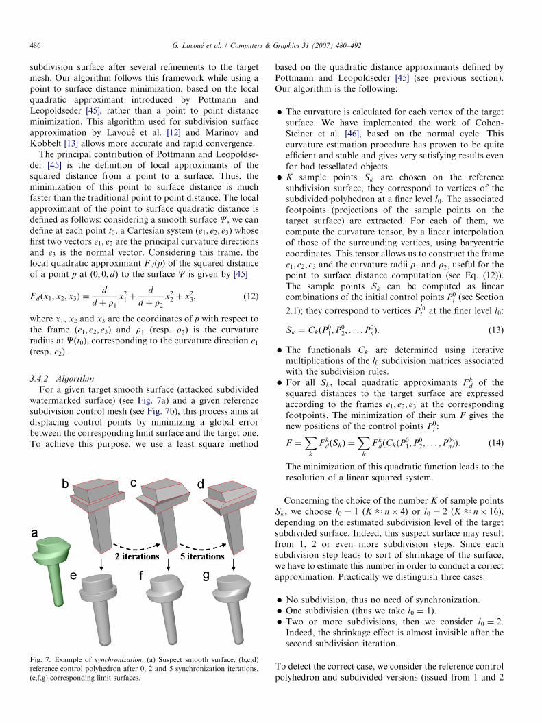
3.4.2. Algorithm
For a given target smooth surface (attacked subdividedwatermarked surface) (see Fig. 7a) and a given referencesubdivision control mesh (see Fig. 7b), this process aims atdisplacing control points by minimizing a global errorbetween the corresponding limit surface and the target one.To achieve this purpose, we use a least square method
Fig. 7. Example of synchronization. (a) Suspect smooth surface, (b,c,d)
reference control polyhedron after 0, 2 and 5 synchronization iterations,
(e,f,g) corresponding limit surfaces.
based on the quadratic distance approximants defined byPottmann and Leopoldseder [45] (see previous section).Our algorithm is the following:
�
The curvature is calculated for each vertex of the targetsurface. We have implemented the work of Cohen-Steiner et al. [46], based on the normal cycle. Thiscurvature estimation procedure has proven to be quiteefficient and stable and gives very satisfying results evenfor bad tessellated objects. � K sample points Sk are chosen on the referencesubdivision surface, they correspond to vertices of thesubdivided polyhedron at a finer level l0. The associatedfootpoints (projections of the sample points on thetarget surface) are extracted. For each of them, wecompute the curvature tensor, by a linear interpolationof those of the surrounding vertices, using barycentriccoordinates. This tensor allows us to construct the framee1; e2; e3 and the curvature radii r1 and r2, useful for thepoint to surface distance computation (see Eq. (12)).The sample points Sk can be computed as linearcombinations of the initial control points P0
i (see Section
2.1); they correspond to vertices Pl0i at the finer level l0:
Sk ¼ CkðP01;P
02; . . . ;P
0nÞ. (13)
�
The functionals Ck are determined using iterativemultiplications of the l0 subdivision matrices associatedwith the subdivision rules. � For all Sk, local quadratic approximants Fkd of thesquared distances to the target surface are expressedaccording to the frames e1; e2; e3 at the correspondingfootpoints. The minimization of their sum F gives thenew positions of the control points P0
i :
F ¼X
k
Fkd ðSkÞ ¼
Xk
F kdðCkðP
01;P
02; . . . ;P
0nÞÞ. (14)
The minimization of this quadratic function leads to theresolution of a linear squared system.
Concerning the choice of the number K of sample pointsSk, we choose l0 ¼ 1 (K � n� 4) or l0 ¼ 2 (K � n� 16),depending on the estimated subdivision level of the targetsubdivided surface. Indeed, this suspect surface may resultfrom 1, 2 or even more subdivision steps. Since eachsubdivision step leads to sort of shrinkage of the surface,we have to estimate this number in order to conduct a correctapproximation. Practically we distinguish three cases:
�
No subdivision, thus no need of synchronization. � One subdivision (thus we take l0 ¼ 1). � Two or more subdivisions, then we consider l0 ¼ 2.Indeed, the shrinkage effect is almost invisible after thesecond subdivision iteration.
To detect the correct case, we consider the reference controlpolyhedron and subdivided versions (issued from 1 and 2
ARTICLE IN PRESSG. Lavoue et al. / Computers & Graphics 31 (2007) 480–492 487
subdivision steps), and we take the version whichminimizes the mean L1 error to the target suspect surface.
Fig. 7a presents a smooth surface coming from foursubdivisions (and possibly attacks) of a watermarkedcontrol mesh (Catmull–Clark rules), thus we considerl0 ¼ 2. The watermark strength has been exaggerated forthis experiment. The reference original subdivision surfaceis shown in Fig. 7b (control mesh) and 7e (limit surface).After only 5 synchronization iterations, the limit surface(Fig. 7g) is perfectly fitted with the suspect one (Fig. 7a).Resulting errors are respectively 3:84� 10�3 and 0:03�10�3 after 2 and 5 iterations (surfaces were normalized in acubic bounding box of length equal to 1). Thus, after 5iterations we have retrieved the shape of the watermarkedcontrol mesh (see Fig. 7d), and we are able to launch thewatermark extraction.
3.5. Complete insertion and extraction algorithms
3.5.1. Watermark insertion
Given a binary mark A of size k to embed, the first step isto produce an m bits code word B ¼ ðb1; b2; . . . ;bmÞ ðm4k), using convolutional encoding (see Section3.3), in order to increase the mark robustness. The con-trol mesh of the subdivision surface to watermark isthen decomposed in the spectral domain (see Section 3.1)to produce the three spectral coefficient vectors P, Q
and R of size n. The m dimensional watermark B (mon)will be embedded in the 3D subdivision control mesh,by modulating these spectral coefficients. In order toincrease the robustness, we have chosen to repeat thewatermark on each vector P, Q and R. Nevertheless, sincea specific attack may alter the same part (high, lowor middle frequencies) of each coordinate spectrum, wehave chosen to shuffle the mark B into three differentversions B1, B2, B3 using three distinct random interleaversI1, I2, I3:
B1 ¼ I1ðBÞ;
B2 ¼ I2ðBÞ;
B3 ¼ I3ðBÞ:
8><>: (15)
Before embedding the binary sequences B1, B2 and B3, wefirst construct the three modulating vectors B10 , B20 and B30
by the following mapping:
bx0
i ¼�1 if bx
i ¼ 0;
1 if bxi ¼ 1;
(i ¼ 1 . . .m; x ¼ 1; 2; 3. (16)
These vectors are then inserted, respectively, in the spectralcomponents P, Q and R using our coefficient modulationalgorithm (see Section 3.2):
pi ¼ pi þ b10
i abi,
qi ¼ qi þ b20
i abi; i ¼ 1 . . .m.
ri ¼ ri þ b30
i abi, ð17Þ
3.5.2. Watermark extraction
The extraction process needs the watermarked (andpossibly attacked) control mesh, the original referencecontrol mesh (i.e. the algorithm is non-blind) and the a andT values.The watermarked control mesh and the original one are
first aligned by a registration process [47]. If the water-marked subdivision surface is in a subdivided form, we firstalign it with the corresponding subdivided version of theoriginal surface (issued from one or two subdivisions, seeSection 3.4), and then apply the synchronization process toretrieve the corresponding watermarked control mesh.Both watermarked and reference control meshes are then
decomposed on the eigenvector basis computed on thereference one. Thus, we obtain, respectively, spectralcoefficients vectors P, Q and R and P, Q and R.Firstly, we extract three real number vectors B1, B2 and
B3 computed as follows:
b1
i ¼pi � pi
abi
,
b2
i ¼qi � qi
abi
; i ¼ 1 . . .m.
b3
i ¼ri � ri
abi
. ð18Þ
Then, these vectors are desinterleaved and summed to givethe m dimensional real number vector B:
B ¼ 13ðI�11 ðB
1Þ þ I�12 ðB2Þ þ I�13 ðB
3ÞÞ. (19)
This vector is then decoded using the soft Viterbi algorithmto give the extracted mark A ¼ ða1; a2; . . . ; akÞ of size k. Thecorrelation, between the embedded watermark A and theextracted one, is defined by
correlation ¼Xi¼k
i¼1
ðCiÞ; Ci ¼1 if ai ¼ ai;
�1 if aiaai:
((20)
4. Experiments and results
We have conducted experiments on several differentsubdivision surfaces. Examples are given for three typicalobjects, from different natures and coming from differentcreation processes. They are illustrated in Fig. 8 (controlmeshes at the top and limit surfaces at the bottom):
(a)
SubPlane (154 control points), whose control mesh wasdirectly hand designed. It is composed of a majority ofquadrangles.(b)
SubRabbit (200 control points), whose control meshcomes from the subdivision surface approximationalgorithm from Kanai [10] applied on the well-knownnatural object Stanford Bunny. It is a triangle onlycontrol mesh.(c)
SubFandisk (86 control points), whose control meshcomes from the subdivision surface approximationalgorithm from Lavoue et al. [12] applied on the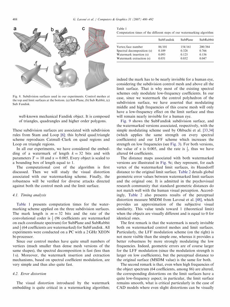
ARTICLE IN PRESS
Fig. 8. Subdivision surfaces used in our experiments. Control meshes at
the top and limit surfaces at the bottom. (a) Sub Plane, (b) Sub Rabbit, (c)
Sub Fandisk.
Table 1
Computation times of the different steps of our watermarking algorithm
SubFandisk SubPlane SubRabbit
Vertex/face number 86/101 154/161 200/384
Spectral decomposition (s) 0.109 0.328 0.766
Watermark insertion (s) 0.093 0.125 0.156
Watermark extraction (s) 0.031 0.032 0.047
G. Lavoue et al. / Computers & Graphics 31 (2007) 480–492488
well-known mechanical Fandisk object. It is composedof triangles, quadrangles and higher order polygons.
These subdivision surfaces are associated with subdivisionrules from Stam and Loop [6]; this hybrid quad/trianglescheme reproduces Catmull–Clark on quad regions andLoop on triangle regions.
In all our experiments, we have considered the embed-ding of a watermark of length k ¼ 32 bits and withparameters T ¼ 10 and a ¼ 0:005. Every object is scaled toa bounding box of length equal to 1.
The computational cost of the algorithm is firstdiscussed. Then we will study the visual distortionassociated with our watermarking scheme. Finally, therobustness will be verified for diverse attacks directedagainst both the control mesh and the limit surface.
4.1. Timing analysis
Table 1 presents computation times for the water-marking scheme applied on the three subdivision surfaces.The mark length is m ¼ 32 bits and the rate of theconvolutional coder is 1
3(96 coefficients are watermarked
on each coordinate spectrum) for SubPlane and SubRabbitand 1
2 (64 coefficients are watermarked) for SubFandisk. Allexperiments were conducted on a PC with a 2GHz XEONbi-processor.
Since our control meshes have quite small numbers ofvertices (much smaller than dense mesh versions of thesame shapes), the spectral decomposition is fast (less than1 s). Moreover, the watermark insertion and extractionmechanisms, based on spectral coefficient modulation, arevery simple and thus also quite fast.
4.2. Error distortion
The visual distortion introduced by the watermarkembedding is quite critical in a watermarking algorithm;
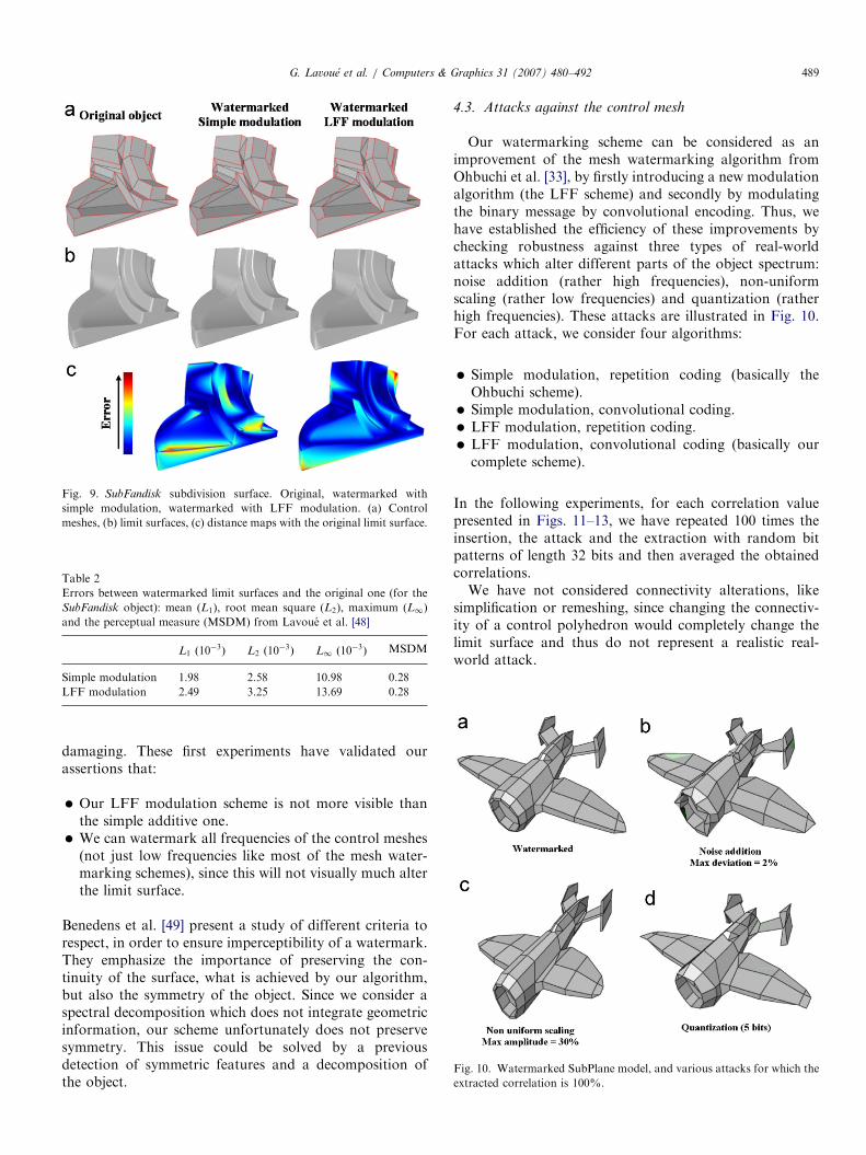
indeed the mark has to be nearly invisible for a human eye,considering the subdivision control mesh and above all thelimit surface. That is why most of the existing spectralschemes only modulate low-frequency coefficients. In ourcase, since we watermark the control polyhedron of thesubdivision surface, we have asserted that modulatingmiddle and high frequencies of this coarse mesh will onlyhave a low-frequency effect on the limit surface and thuswill remain nearly invisible for a human eye.Fig. 9 shows the SubFandisk subdivision surface, and
the watermarked versions associated, respectively, with thesimple modulating scheme used by Ohbuchi et al. [33,34](which applies the same strength on every spectralcoefficients) and our LFF scheme which increases thestrength on low frequencies (see Fig. 3). For both versions,the value of a is 0:005, and the rate is 1
2, thus we have
altered 64 coefficients.The distance maps associated with both watermarked
versions are illustrated in Fig. 9c; they represent, for eachvertex of the watermarked limit surfaces, its Hausdorffdistance to the original limit surface. Table 2 details globalgeometric error values between watermarked limit surfacesand the original one. It is admitted in the psychovisualresearch community that standard geometric distances donot match well with the human visual perception. Accord-ingly, Table 2 also presents results of the perceptualdistortion measure MSDM from Lavoue et al. [48], whichprovides an approximation of the subjective visualsimilarity. This value tends toward 1 (theoretical limit)when the objects are visually different and is equal to 0 foridentical ones.The first remark is that the watermark is nearly invisible
both on watermarked control meshes and limit surfaces.Particularly, the LFF modulation scheme (on the right) isnot more visible than the simple one, whereas it provides abetter robustness by more strongly modulating the lowfrequencies. Indeed, geometric errors are of course largerfor the LFF modulation (since the modulation strength islarger on low coefficients), but the perceptual distance tothe original surface (MSDM value) is the same for both.The second remark is that, even when high frequencies of
the object spectrum (64 coefficients, among 86) are altered,the corresponding distortions on the limit surfaces have aquite low-frequency aspect; in particular, the limit surfaceremains smooth, what is critical particularly in the case ofCAD models where even slight distortions can be visually
ARTICLE IN PRESS
Table 2
Errors between watermarked limit surfaces and the original one (for the
SubFandisk object): mean (L1), root mean square (L2), maximum (L1)
and the perceptual measure (MSDM) from Lavoue et al. [48]
L1 ð10�3Þ L2 ð10
�3Þ L1 ð10�3Þ MSDM
Simple modulation 1.98 2.58 10.98 0.28
LFF modulation 2.49 3.25 13.69 0.28
Fig. 9. SubFandisk subdivision surface. Original, watermarked with
simple modulation, watermarked with LFF modulation. (a) Control
meshes, (b) limit surfaces, (c) distance maps with the original limit surface.
G. Lavoue et al. / Computers & Graphics 31 (2007) 480–492 489
damaging. These first experiments have validated ourassertions that:
�
Our LFF modulation scheme is not more visible thanthe simple additive one. �Fig. 10. Watermarked SubPlane model, and various attacks for which the
extracted correlation is 100%.
We can watermark all frequencies of the control meshes(not just low frequencies like most of the mesh water-marking schemes), since this will not visually much alterthe limit surface.
Benedens et al. [49] present a study of different criteria torespect, in order to ensure imperceptibility of a watermark.They emphasize the importance of preserving the con-tinuity of the surface, what is achieved by our algorithm,but also the symmetry of the object. Since we consider aspectral decomposition which does not integrate geometricinformation, our scheme unfortunately does not preservesymmetry. This issue could be solved by a previousdetection of symmetric features and a decomposition ofthe object.
4.3. Attacks against the control mesh
Our watermarking scheme can be considered as animprovement of the mesh watermarking algorithm fromOhbuchi et al. [33], by firstly introducing a new modulationalgorithm (the LFF scheme) and secondly by modulatingthe binary message by convolutional encoding. Thus, wehave established the efficiency of these improvements bychecking robustness against three types of real-worldattacks which alter different parts of the object spectrum:noise addition (rather high frequencies), non-uniformscaling (rather low frequencies) and quantization (ratherhigh frequencies). These attacks are illustrated in Fig. 10.For each attack, we consider four algorithms:
�
Simple modulation, repetition coding (basically theOhbuchi scheme). � Simple modulation, convolutional coding. � LFF modulation, repetition coding. � LFF modulation, convolutional coding (basically ourcomplete scheme).
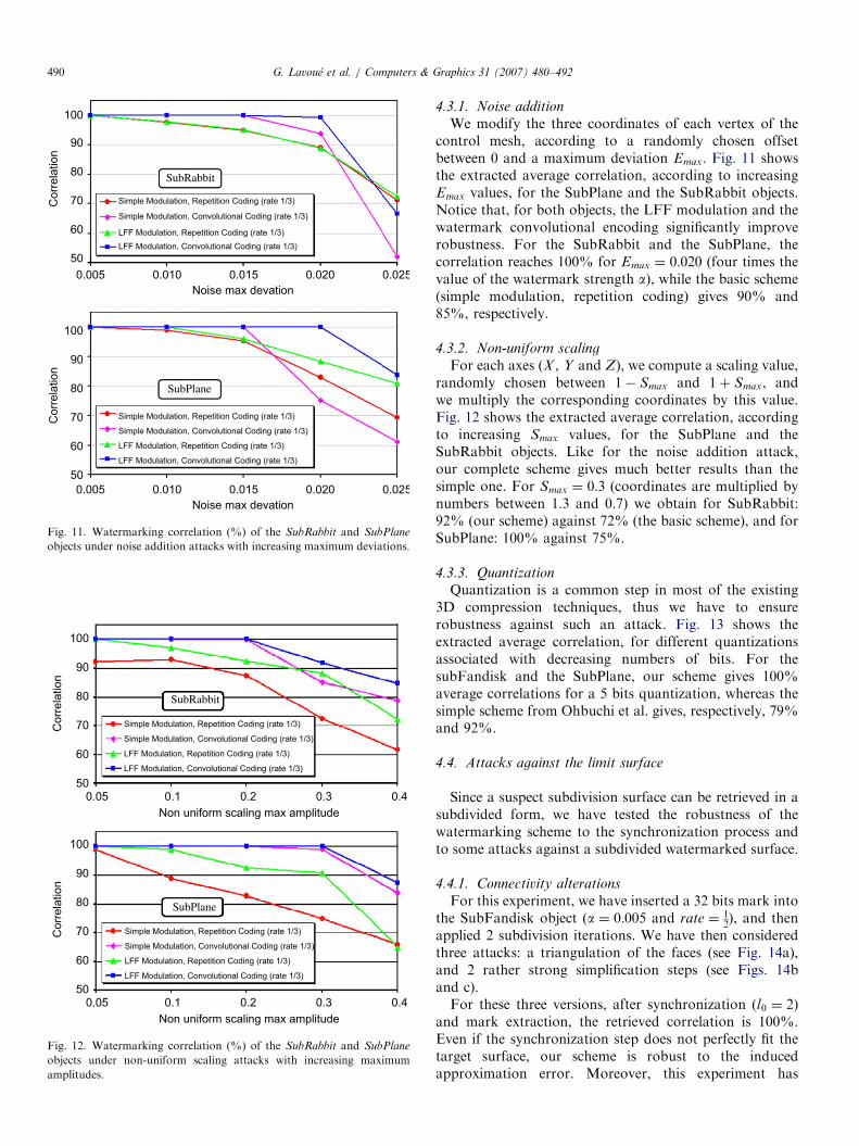
In the following experiments, for each correlation valuepresented in Figs. 11–13, we have repeated 100 times theinsertion, the attack and the extraction with random bitpatterns of length 32 bits and then averaged the obtainedcorrelations.We have not considered connectivity alterations, like
simplification or remeshing, since changing the connectiv-ity of a control polyhedron would completely change thelimit surface and thus do not represent a realistic real-world attack.
ARTICLE IN PRESS
0.005 0.010 0.015 0.020 0.025
Noise max devation
0.005 0.010 0.015 0.020 0.025
Noise max devation
100
90
80
70
60
50
Corr
ela
tion
SubRabbit
Simple Modulation, Repetition Coding (rate 1/3)
LFF Modulation, Repetition Coding (rate 1/3)
Simple Modulation, Convolutional Coding (rate 1/3)
LFF Modulation, Convolutional Coding (rate 1/3)
100
90
80
70
60
50
Corr
ela
tion
Simple Modulation, Repetition Coding (rate 1/3)
LFF Modulation, Repetition Coding (rate 1/3)
Simple Modulation, Convolutional Coding (rate 1/3)
LFF Modulation, Convolutional Coding (rate 1/3)
SubPlane
Fig. 11. Watermarking correlation (%) of the SubRabbit and SubPlane
objects under noise addition attacks with increasing maximum deviations.
100
90
80
70
60
50
Corr
ela
tion
SubRabbit
Simple Modulation, Repetition Coding (rate 1/3)
LFF Modulation, Repetition Coding (rate 1/3)
Simple Modulation, Convolutional Coding (rate 1/3)
LFF Modulation, Convolutional Coding (rate 1/3)
Simple Modulation, Repetition Coding (rate 1/3)
LFF Modulation, Repetition Coding (rate 1/3)
Simple Modulation, Convolutional Coding (rate 1/3)
LFF Modulation, Convolutional Coding (rate 1/3)
SubPlane
0.05 0.1 0.2 0.3 0.4
Non uniform scaling max amplitude
100
90
80
70
60
50
Corr
ela
tion
0.05 0.1 0.2 0.3 0.4
Non uniform scaling max amplitude
Fig. 12. Watermarking correlation (%) of the SubRabbit and SubPlane
objects under non-uniform scaling attacks with increasing maximum
amplitudes.
G. Lavoue et al. / Computers & Graphics 31 (2007) 480–492490
4.3.1. Noise addition
We modify the three coordinates of each vertex of thecontrol mesh, according to a randomly chosen offsetbetween 0 and a maximum deviation Emax. Fig. 11 showsthe extracted average correlation, according to increasingEmax values, for the SubPlane and the SubRabbit objects.Notice that, for both objects, the LFF modulation and thewatermark convolutional encoding significantly improverobustness. For the SubRabbit and the SubPlane, thecorrelation reaches 100% for Emax ¼ 0:020 (four times thevalue of the watermark strength a), while the basic scheme(simple modulation, repetition coding) gives 90% and85%, respectively.
4.3.2. Non-uniform scaling
For each axes (X , Y and Z), we compute a scaling value,randomly chosen between 1� Smax and 1þ Smax, andwe multiply the corresponding coordinates by this value.Fig. 12 shows the extracted average correlation, accordingto increasing Smax values, for the SubPlane and theSubRabbit objects. Like for the noise addition attack,our complete scheme gives much better results than thesimple one. For Smax ¼ 0:3 (coordinates are multiplied bynumbers between 1:3 and 0:7) we obtain for SubRabbit:92% (our scheme) against 72% (the basic scheme), and forSubPlane: 100% against 75%.
4.3.3. Quantization
Quantization is a common step in most of the existing3D compression techniques, thus we have to ensurerobustness against such an attack. Fig. 13 shows theextracted average correlation, for different quantizationsassociated with decreasing numbers of bits. For thesubFandisk and the SubPlane, our scheme gives 100%average correlations for a 5 bits quantization, whereas thesimple scheme from Ohbuchi et al. gives, respectively, 79%and 92%.
4.4. Attacks against the limit surface
Since a suspect subdivision surface can be retrieved in asubdivided form, we have tested the robustness of thewatermarking scheme to the synchronization process andto some attacks against a subdivided watermarked surface.
4.4.1. Connectivity alterations
For this experiment, we have inserted a 32 bits mark intothe SubFandisk object (a ¼ 0:005 and rate ¼ 1
2), and then
applied 2 subdivision iterations. We have then consideredthree attacks: a triangulation of the faces (see Fig. 14a),and 2 rather strong simplification steps (see Figs. 14band c).For these three versions, after synchronization (l0 ¼ 2)
and mark extraction, the retrieved correlation is 100%.Even if the synchronization step does not perfectly fit thetarget surface, our scheme is robust to the inducedapproximation error. Moreover, this experiment has

ARTICLE IN PRESS
8 7 6 5 4
Nb bits Quantization
100
90
80
70
60
50
Corr
ela
tion
8 7 6 5 4
Nb bits Quantization
100
90
80
70
60
50
Corr
ela
tion
SubFandisk
Simple Modulation, Repetition Coding (rate 1/2)
LFF Modulation, Repetition Coding (rate 1/2)
Simple Modulation, Convolutional Coding (rate 1/2)
LFF Modulation, Convolutional Coding (rate 1/2)
Simple Modulation, Repetition Coding (rate 1/3)
LFF Modulation, Repetition Coding (rate 1/3)
Simple Modulation, Convolutional Coding (rate 1/3)
LFF Modulation, Convolutional Coding (rate 1/3)
SubPlane
Fig. 13. Watermarking correlation (%) of the SubFandisk and SubPlane
objects submitted to different quantizations.
Fig. 14. Watermarked SubFandisk object after 2 subdivision iterations
and triangulation (a), and 2 simplification steps (b,c). The extracted
correlation is 100%. (a) 1282 vertices, (b) 270 vertices, (c) 110 vertices.
Fig. 15. Watermarked SubFandisk object after 3 subdivision iterations (a)
and noise addition (b). The extracted correlation is 100%.
G. Lavoue et al. / Computers & Graphics 31 (2007) 480–492 491
proven the high robustness to hard connectivity alterationslike the simplifications illustrated in Figs. 14b and c.
4.4.2. Geometry alterations
In order to establish the robustness of our scheme togeometric attacks against the subdivided watermarked sur-face, we have considered the watermarked SubFandisk object(a ¼ 0:005 and rate ¼ 1
2), after three subdivision iterations (see
Fig. 15a) and noise addition (see Fig. 15b). The synchroniza-tion is processed with l0 ¼ 2, and we obtain for both case a100% correlation, after the mark extraction. Even if the noiseamplitude is not very high (max : deviation ¼ ð0:4%Þ, thisresult is quite satisfying since we have just watermarked thecoarse control polyhedron (86 vertices).
5. Conclusion
We have presented a robust watermarking scheme forsubdivision surfaces, based on the modulation of spectral
coefficients of the subdivision control mesh. Due to thecompactness of the cover object (a coarse control mesh),our algorithm optimizes the trade-off between water-marking redundancy and imperceptibility by modulatingcoefficients according to a new scheme (LFF) and by usingECC. Experiments have shown an average 20% improve-ment of the robustness, compared with a standardmodulation scheme [34].Since a watermarked subdivision surface can be captured
and/or attacked in a subdivided (i.e. smooth) version, wehave also introduced a synchronization process allowing toretrieve the corresponding control mesh and to correctlyextract the mark. This process provides efficient robustnessagainst remeshing or simplification attacks which areconsidered critical issues according to evaluation criteriafrom Benedens et al. [49].Concerning future work, we plan to investigate other
types of ECC, providing robustness even for very severeattacks, since convolutional coding efficiency tends to falldown in such cases. It should be useful to modelize thespectral distortion introduced by the different types ofattacks (noise addition, quantization, scaling, etc.) in orderto construct specific correcting schemes.Finally, the properties of subdivision surfaces could be
exploited to design blind watermarking schemes; aninteresting idea could be to use connectivity properties(semi-regularity) of limit surfaces.
References
[1] Cox I-J, Miller M-L, Bloom J-A. Digital watermarking. Los Altos,
CA: Morgan Kaufman; 2002.
[2] MPEG4, Iso-iec 14496-16. Coding of audio-visual objects: animation
framework extension (afx), 2006.
[3] Doo D, Sabin M. Behavior of recursive division surfaces near
extraordinary points. Computer Aided Design 1978;10:356–60.
[4] Catmull E, Clark J. Recursively generated b-spline surfaces on
arbitrary topological meshes. Computer-Aided Design 1978;10(6):
350–5.
[5] Loop C. Smooth subdivision surfaces based on triangles. Master’s
thesis, Utah University, 1987.
[6] Stam J, Loop C. Quad/triangle subdivision. Computer Graphics
Forum 2003;22(1):79–85.

ARTICLE IN PRESSG. Lavoue et al. / Computers & Graphics 31 (2007) 480–492492
[7] Hoppe H, DeRose T, Duchamp T, Halstead M, Jin H, McDonald J,
et al. Piecewise smooth surface reconstruction. In: ACM Siggraph,
vol. 28; 1994. p. 295–302.
[8] Suzuki H. Subdivision surface fitting to a range of points. In: IEEE
Pacific graphics; 1999. p. 158–67.
[9] Lee A, Moreton H, Hoppe H. Displaced subdivision surfaces. In:
ACM Siggraph; 2000. p. 85–94.
[10] Kanai T. Meshtoss—converting subdivision surfaces from dense
meshes. In: The sixth international workshop on vision, modeling and
visualization; 2001. p. 325–32.
[11] Ma W, Ma X, Tso S, Pan Z. A direct approach for subdivision
surface fitting from a dense triangle mesh. Computer Aided Design
2004;36(16):525–36.
[12] Lavoue G, Dupont F, Baskurt A. A framework for quad/triangle
subdivision surface fitting: application to mechanical objects.
Computer Graphics Forum 2007;26(1) to appear.
[13] Marinov M, Kobbelt L. Optimization methods for scattered data
approximation with subdivision surfaces. Graphical Models 2005;
67(5):452–73.
[14] Ohbuchi R, Masuda H, Aono M. A shape-preserving data
embedding algorithm for nurbs curves and surfaces. In: IEEE
computer graphics international; 1999. p. 180–7.
[15] Lee J-J, Cho N-I, Lee S-U. Watermarking algorithms for 3d nurbs
graphic data. EURASIP Journal on Applied Signal Processing
2004;14:2142–52.
[16] Ohbuchi R, Masuda H, Aono M. Watermarking three-dimensional
polygonal meshes. In: ACM multimedia; 1997. p. 261–72.
[17] Ohbuchi R, Masuda H, Aono M. Watermarking three-dimensional
polygonal models through geometric and topological modifications.
IEEE Journal on Selected Areas in Communication 1998;16(4):
551–9.
[18] Yeo B-L, Yeung M-M. Watermarking 3d objects for verification.
IEEE Computer Graphics and Applications 1999;19(1):36–45.
[19] Cayre F, Macq B. Data hiding on 3-d triangle meshes. IEEE
Transactions on Signal Processing 2003;51(4):939–49.
[20] Benedens O. Geometry-based watermarking of 3d models. IEEE
Computer Graphics and Application 1999;19(1):46–55.
[21] Benedens O, Busch C. Toward blind detection of robust water-
marks in polygonal models. Computer Graphics Forum 2000;19:
199–208.
[22] Yu Z, Ip H-H, Wok L-F. A robust watermarking scheme
for 3d triangular mesh models. Pattern Recognition 2003;
36(11):2603–14.
[23] Maret Y, Ebrahimi T. Data hiding on 3d polygonal meshes. In: ACM
workshop on multimedia and security; 2004. p. 68–74.
[24] Zafeiriou S, Tefas A, Pitas I. Blind robust watermarking schemes for
copyright protection of 3d mesh objects. IEEE Transactions on
Visualization and Computer Graphics 2005;11(5):596–607.
[25] Kanai S, Date H, Kishinami T. Digital watermarking for 3d polygons
using multi-resolution wavelet decomposition. In: IFIP WG 5.2
International workshop on geometric modeling: fundamental and
application (GEO-6); 1998. p. 296–307.
[26] Lounsbery M, DeRose T-D, Warren J. Multiresolution analysis for
surfaces of arbitrary topological type. ACM transactions on graphics
1997;16(1):34–73.
[27] Uccheddu F, Corsini M, Barni M. Wavelet-based blind water-
marking of 3d models. In: ACM workshop on multimedia and
security; 2004. p. 143–54.
[28] Kim M-S, Valette S, Jung H-Y, Prost R. Watermarking of 3d
irregular meshes based on wavelet multiresolution analysis, Lecture
notes in computer Science, vol. 3710. In: Proceedings of IWDW,
2005. p. 313–24.
[29] Praun E, Hoppe H, Finkelstein H. Robust mesh watermarking. In:
Siggraph; 1999. p. 69–76.
[30] Hoppe H. Progressive meshes. In: ACM Siggraph; 1996. p. 99–108.
[31] Yin K, Pan Z, Shi J, Hang D. Robust mesh watermarking based on
multiresolution processing. Computers and Graphics 2001;25(3):
409–20.
[32] Guskov I, Sweldens W, Shroder P. Multiresolution signal processing
for meshes. In: ACM Siggraph; 1999. p. 49–56.
[33] Ohbuchi R, Takahashi S, Miyazawa T, Mukaiyama A. Water-
marking 3d polygonal meshes in the mesh spectral domain. In:
Graphic interface; 2001. p. 9–17.
[34] Ohbuchi R, Mukaiyama A, Takahashi S. A frequency-domain
approach to watermarking 3d shapes. Computer Graphic forum
2002;21(3):373–82.
[35] Karni Z, Gotsman C. Spectral compression of mesh geometry. In:
ACM Siggraph; 2000. p. 279–86.
[36] Wu J, Kobbelt L. Efficient spectral watermarking of large meshes
with orthogonal basis functions. The Visual Computers 2005;
21(8–10):848–57.
[37] Li L, Zhang D, Pan Z, Shi J, Zhou K, Kai Y. Watermarking 3d mesh
by spherical parameterization. Computers and Graphics 2004;
28(6):981–9.
[38] Cayre F, Rondao-Alface P, Schmitt F, Macq B, Maıtre H.
Application of spectral decomposition to compression and water-
marking of 3d triangle mesh geometry. Signal Processing : Image
Communications 2003;18(4):309–19.
[39] Bollabas B. Modern graph theory. Berlin: Springer; 1998.
[40] Cox I-J, Killian J, Leighton T, Shamoon T. Secure spread spectrum
watermarking for multimedia. IEEE Transactions on Image Proces-
sing 1997;12(6):1673–87.
[41] Sorkine O, Cohen-Or D, Toldeo S. High-pass quantization for mesh
encoding. In: Eurographics symposium on geometry processing;
2003. p. 42–51.
[42] Cox I-J, Miller M-L, McKellips A-L. Watermarking as communica-
tions with side information. Proceedings of the IEEE 1999;87(7):
1127–41.
[43] Baudry S, Delaigle J-F, Sankur B, Macq B, Maitre H. Analyses of
error correction strategies for typical communication channels in
watermarking. Signal Processing 2001;81(6):1239–50.
[44] Viterbi A. Error bounds for convolution codes and an asymptotically
optimum decoding algorithm. IEEE Transactions on Information
Theory 1967;13:260–9.
[45] Pottmann H, Leopoldseder S. A concept for parametric surface
fitting which avoids the parametrization problem. Computer Aided
Geometric Design 2003;20(6):343–62.
[46] Cohen-Steiner D, Morvan J. Restricted delaunay triangulations and
normal cycle. In: 19th annual ACM symposium computation
geometry, 2003.
[47] Besl P-J, McKay N-D. A method for registration of 3-d shapes. IEEE
Transactions on Pattern Analysis and Machine Intelligence
1992;14(2):239–56.
[48] Lavoue G, Drelie Gelasca E, Dupont F, Baskurt A, Ebrahimi T.
Perceptually driven 3d distance metrics with application to water-
marking. In: SPIE applications of digital image processing XXIX,
vol. 6312; 2006.
[49] Benedens O, Dittmann J, Petitcolas F. 3d watermarking design
evaluation. In: SPIE security and watermarking of multimedia
contents V, vol. 5020; 2003. p. 337–48.