TECHNICAL REPORT STANDARD TITLE PAGE · TECHNICAL REPORT STANDARD TITLE PAGE 1. ... Daniel B....
52
TECHNICAL REPORT STANDARD TITLE PAGE 1. Report No. 2. GoYemmem Aocellion No. 3. Recipient's Catalog No. TX-92/990-2 4. Title and Subtille 5. Report Date Recommended Design Guidelines for the November 1991 Vertical Alignment of Driveways 6. Performing Orpniz.ation Code 7. Autbor(s) 8. Organization Report No. Marc D. Williams, Daniel B. Fambro, and Vergil G. Stover Research Report 990-2 _9._ Performing _Organization.Name and Address ----- --10. -Work-Unit-No.- Texas Transportation Institute Texas A&M University 11. Contract or Grant No. College Station, Texas 77843-3135 Study No. 2-8-90/9901G . 12. Sponsoring Agency Name and .Addrea 13. 'fype oC Report and Period Covered Texas Department of Transportation Transportation Planning Division Final-- May, 1990 P.O. Box 5051 August, 1991 Austin, Texas 78763 14. Sponsoring Agency Code 15. Supplementiuy Notes Research performed in cooperation with the state of Texas. Study Title: Recommended Design Guidelines for the Vertical Alignment of Driveways 16. Abstr.m This report outlines preliminary vertical curve alignment guidelines for the design of driveways. It is intended to be an aid for highway engineers involved with the design of driveways for access locations with restricted right of way and steep vertical alignment. Guidelines are recommended that will allow designs to meet minimum safety and operational criteria. In addition to the design guidelines, the report discusses various elements. that should be considered in formulating a design that includes site characteristics, functional requirements, and design vehicles. Based on these factors, requirements for maximum and minimum driveway grades and lengths of grades are established. In addition, this report provides a procedural framework for implementation in design and analysis. By utilizing this framework, the engineer develops initial design considerations based on geometries and functional requirements, formulates the design according to maximum and minimum geometric guidelines, tests the design to accommodate design vehicles, and then retests the design with respect to the geometric guidelines. Application of the guidelines and procedures provided in this report will enable engineers to be more confident in the safety and operational effectiveness of their design. 17. KeyWord5 18. Distribution Statement Driveway, Vertical Alignment, No restriction. This document is available to Right-of-Way, Slope of Grade, the public through the National Technical Grade-Break Angle, Length of Grade, Information Service, 5285 Port Royal Rd., Design Vehicle Springfield, VA 22161 19. Security Classi!. (of this report) 20. Security Ciassit. (of this page) 21. No. of Pages 22.. Price Unclassified Unclassified 53 Form DOT F 1700.7 (8-69)
Transcript of TECHNICAL REPORT STANDARD TITLE PAGE · TECHNICAL REPORT STANDARD TITLE PAGE 1. ... Daniel B....

TECHNICAL REPORT STANDARD TITLE PAGE 1. Report No. 2. GoYemmem Aocellion No. 3. Recipient's Catalog No.
TX-92/990-2
4. Title and Subtille 5. Report Date
Recommended Design Guidelines for the November 1991 Vertical Alignment of Driveways 6. Performing Orpniz.ation Code
7. Autbor(s) 8. P~rtorming Organization Report No.
Marc D. Williams, Daniel B. Fambro, and Vergil G. Stover Research Report 990-2 _9._ Performing _Organization.Name and Address ----- --10. -Work-Unit-No.-
Texas Transportation Institute Texas A&M University 11. Contract or Grant No.
College Station, Texas 77843-3135 Study No. 2-8-90/9901G .
12. Sponsoring Agency Name and .Addrea 13. 'fype oC Report and Period Covered
Texas Department of Transportation Transportation Planning Division Final-- May, 1990 P.O. Box 5051 August, 1991 Austin, Texas 78763 14. Sponsoring Agency Code
15. Supplementiuy Notes
Research performed in cooperation with the state of Texas. Study Title: Recommended Design Guidelines for the Vertical Alignment of Driveways
16. Abstr.m
This report outlines preliminary vertical curve alignment guidelines for the design of driveways. It is intended to be an aid for highway engineers involved with the design of driveways for access locations with restricted right of way and steep vertical alignment. Guidelines are recommended that will allow designs to meet minimum safety and operational criteria. In addition to the design guidelines, the report discusses various elements. that should be considered in formulating a design that includes site characteristics, functional requirements, and design vehicles. Based on these factors, requirements for maximum and minimum driveway grades and lengths of grades are established. In addition, this report provides a procedural framework for implementation in design and analysis. By utilizing this framework, the engineer develops initial design considerations based on geometries and functional requirements, formulates the design according to maximum and minimum geometric guidelines, tests the design to accommodate design vehicles, and then retests the design with respect to the geometric guidelines. Application of the guidelines and procedures provided in this report will enable engineers to be more confident in the safety and operational effectiveness of their design.
17. KeyWord5 18. Distribution Statement
Driveway, Vertical Alignment, No restriction. This document is available to Right-of-Way, Slope of Grade, the public through the National Technical Grade-Break Angle, Length of Grade, Information Service, 5285 Port Royal Rd., Design Vehicle Springfield, VA 22161
19. Security Classi!. (of this report) 20. Security Ciassit. (of this page) 21. No. of Pages 22.. Price
Unclassified Unclassified 53
Form DOT F 1700.7 (8-69)

RECOMMENDED DESIGN GUIDELINES FOR THE VERTICAL ALIGNMENT OF DRIVEWAYS
by
Marc D. Williams Engineering Research Assistant Texas Transportation Institute
Daniel B. Fambro, P.E. Assistant Research Engineer
Texas Transportation Institute
Vergil 0. Stover, P.E. Research Engineer
Texas Transportation Institute
Research Report 99010-1 Research Study Number 2-8-90/1-99010
Sponsored by the Texas State Department of Highways and Public Transportation
November 1991
TEXAS TRANSPORTATION INSTITUTE The Texas A&M University System
College Station, Texas 77843
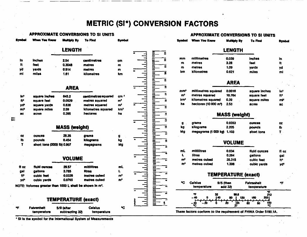
METRIC (SI*) CONVERSION FACTORS APPROXIMATE CONVERSIONS TO SI UNITS APPROXIMATE CONVERSIONS TO SI UNITS .,..... '"-Y•ic-
llulllplr " To Find .,.....
""""" '"-Yau IC- Mulllply llJ To Find """"" LENGTH LENGTH •
~ ::
In Inches 2.54 centtmetrn :: mm mllllmelrea 0.039 Inches In cm ---= ~ m metres 3.28 '"' It It feet 0.3048 metro• m ;; metres 1.09 yards yd ~ m yd yanll 0.914 metros m • km kllomelrea 0.821 mlles ml ml mile• 1.111 kllomelros km § II
---= = AREA =
AREA ~ ~ = mm• mHllmetres squ1rod 0.0018 1quaro Inches In'
In' squaro lnchee 1145.2 centtmotrnsquarod cm' § :: m' metres squ•red 10.784 1quare tu1 It'
It' squaro feel 0.0929 metros squared m' - = km' kllometros squarod 0.39 square mlles ml' yd' squaro yard• 0.838 metro• squarod m' • = ha hecloros (10 000 m'I 2.53 acres ac - :: ml' squaro mlln 2.59 kllomelros squarod km' ~ IC acres 0.395 hectaroa ha --:::: :: MASS (Weight) §§ e:
§ = • II grams 0.0353 ounces oz MASS (Weight) § = kg kllogram1 2.205 pounds lb
: =
Mg megagroms (1 000 kal 1. 103 short Iona T oz ounce• 28.35 oram• 0 ~ lb pounds 0.454 kilograms kg • ~ VOLUME T lhort Ions (2000 lb) 0.807 megaoram1 Mo s
• ~ ml mlllllllros 0.034 fluid ounces II oz - • l lllres 0.284 gallons • ~ gal
VOLUME ~· ~ m• metres cubed 35.315 cubic feel It' E- m• metros cubed 1.308 cubic yanls yd' ft oz ftuld ouncn 29.57 mlllllllrea ml
~ • 11•• gallons 3.785 "''" l
• w TEMPERATURE. (exact) II' cubic feel 0.0328 inetreacubod m' § yd' cubic yanl• 0.0785 metres cubed m' : ~ • ec Celalus 9/5 (then Fahronhall •f
NOTE: Volumes groat• l"8n 1000 l lhlll be lhown In m•. " lemperoturo Hd32) temperoluro E "F
" "F 32 .... 212 - = -~ .. I~ I I i~1 ·I~.~'?!'. I •1!". I .2!>0, TEMPERATURE (exact) • -: ! = s _ol() f -io i ~ I I IO ( dO I 100 'C 37 'C
Of Fahrenheit 5/9(•11• Celalua ec temperaluro 1ublractlng 32) temperaturo Those lactora conform to the roqulroment of FHWA Order 5180.iA.
• SI la the symbol for tho lntematlonal System of Measuroments

ABSTRACT
This report outlines preliminary vertical curve alignment guidelines for the design of driveways. It is intended to be an aid for highway engineers involved with the design of driveways for access locations with restricted right-of-way and steep vertical alignment. Guidelines are recommended that will allow designs to meet minimum safety and operational criteria. In addition to the design guidelines, the report discusses various elements that should be considered in formulating a design that includes site characteristics, functional requirements, and design vehicles. Based on these factors, requirements for maximum and minimum driveway grades and lengths of grades are established. In addition, this report provides a procedural framework for implementation in design and analysis. By utilizing this framework, the engineer develops initial design considerations based on geometries and functional requirements, formulates the design according to maximum and minimum geometric guidelines, tests the design to accommodate design vehicles, and then retests the design with respect to the geometric guidelines. Application of the guidelines and procedures provided in this report will enable engineers to be more confident in the safety and operational effectiveness of their design.
iv

ACKNOWLEDGEMENTS
The development of this report was performed as part of a cooperative research study entitled "Proposed Development of Vertical Alignment Guidelines for Driveways." The research was conducted by the Texas Transportation Institute and sponsored by the Texas Department of Transportation. Dr. Daniel B. Fambro and Mr. Marc D. Williams of the Texas Transportation Institute respectively served as the research supervisor and primary author.
The authors wish to thank Mr. Mark A Marek, Mr. Harold D. Cooner, and Ms. Elizabeth Hilton of the Texas Department of Transportation for their technical assistance and suggestions through the project duration. Thanks is also extended to several Research Assistants and Student Technicians with the Texas Transportation Institute -- Mr. John Habermann and Mr. Richard Harper for their help with field surveys, Mr. Jerry Henderson, Mr. Chris Hoff, and Mr. Steve Venglar for their help in spreadsheet development and preparation of the appendices, and to Ms. Laura Arabie and Ms. Stacy Wyrwich who assisted with the report's technical editing.
DISCLAIMER
The contents of this report reflect the views of the authors who are responsible for the opinions, findings, and conclusions presented herein. The contents do not necessarily reflect the official views or policies of the Federal Highway Administration or the Texas Department of Transportation. This report does not constitute a standard, specification, or regulation. This report is not intended for construction, bidding, or permit purposes.
v
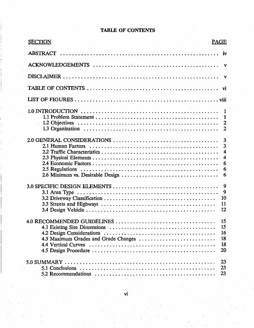
TABLE OF CONTENTS
SECTION PAGE
ABS1RACT . . . . . . . . . . . . . . . . . . . . . . . . . . . . . . . . . . . . . . . . . . . . . . . . . . . . . . iv
ACKNOWLEDGEMENTS . . . . . . . . . . . . . . . . . . . . . . . . . . . . . . . . . . . . . . . . . . . v
DISCLAIMER . . . . . . . . . . . . . . . . . . . . . . . . . . . . . . . . . . . . . . . . . . . . . . . . . . . . . v
TABLE OF CONTENTS . . . . . . . . . . . . . . . . . . . . . . . . . . . . . . . . . . . . . . . . . . . . . vi
UST OF FIGURES ................................................. viii
1.0 IN1RODUCTION . . . . . . . . . . . . . . . . . . . . . . . . . . . . . . . . . . . . . . . . . . . . . . . 1 1.1 Problem Statement . . . . . . . . . . . . . . . . . . . . . . . . . . . . . . . . . . . . . . . . . . 1 1.2 Objectives . . . . . . . . . . . . . . . . . . . . . . . . . . . . . . . . . . . . . . . . . . . . . . . . 2 1.3 Organization .... · . . . . . . . . . . . . . . . . . . . . . . . . . . . . . . . . . . . . . . . . . . 2
2.0 GENERAL CONSIDERATIONS . . . . . . . . . . . . . . . . . . . . . . . . . . . . . . . . . . . . 3 2.1 Human Factors ............................. ; . . . . . . . . . . . . . . 3 22 Traffic Characteristics . . . . . . . . . . . . . . . . . . . . . . . . . . . . . . . . . . . . . . . . 4 2.3 Physical Elements . . . . . . . . . . . . . . . . . . . . . . . . . . . . . . . . . . . . . • . . . . . 4 2.4 Economic Factors . . . . . . . . . . . . . . . . . . . . . . . . . . . . . . . . . . . . . . . . . . . 6 2.5 Regulations . . . . . . . . . . . . . . . . . . . . . . . . . . . . . . . . . . . . . . . . . . . . . . . 6 2.6 Minimum vs. Desirable Design . . . . . . . . . . . . . . . . . . . . . . . . . . . . . . . . . 6
3.0 SPECIFIC DESIGN ELEMENTS . . . . . . . . . . . . . . . . . . . . . . . . . . . . . . . . . . . . 9 3.1 Area Type . . . . . . . . . . . . . . . . . . . . . . . . . . . . . . . . . . . . . . . . . . . . . . . . 9 32 Driveway Classification . . . . . . . . . . . . . . . . . . . . . . . . . . . . . . . . . . . . . . 10 3.3 Streets and Highways . . . . . . . . . . . . . . . . . . . . . . . . . . . . . . . . . . . . . . . 11 3.4 Design Vehicle . . . . . . . . . . . . . . . . . . . . . . . . . . . . . . . . . . . . . . . . . . . . 12
4.0 RECOMMENDED GUIDEUNES . . . . . . . . . . . . . . . . . . . . . . . . . . . . . . . . . . 15 4.1 Existing Site Dimensions . . . . . . . . . . . . . . . . . . . . . . . . . . . . . . . . . . . . 15 4.2 Design Considerations . . . . . . . . . . . . . . . . . . . . . . . . . . . . . . . . . . . . . . 16 4.3 Maximum Grades and Grade Changes . . . . . . . . . . . . . . . . . . . . . . . . . . 18 4.4 Vertical Curves . . . . . . . . . . . . . . . . . . . . . . . . . . . . . . . . . . . . . . . . . . . 18 4.5 Design Procedure . . . . . . . . . . . . . . . . . . . . . . . . . . . . . . . . . . . . . . . . . . 20
5.0 SUMMARY . . . . . . . . . . . . . . . . . . . . . . . . . . . . . . . . . . . . . . . . . . . . . . . . . . . 23 5.1 Conclusions . . . . . . . . . . . . . . . . . . . . . . . . . . . . . . . . . . . . . . . . . . . . . . 23 5.2 Recommendations . . . . . . . . . . . . . . . . . . . . . . . . . . . . . . . . . . . . . . . . . 23
vi
SECTION PAGE
6.0 REFERENCES . . . . . . . . . . . . . . . . . . . . . . . . . . . . . . . . . . . . . . . . . . . . . . . . 25
APPENDIX A - Examples of Existing Driveway Designs . . . . . . . . . . . . . . . . . . . . 27
APPENDIX B - Example Spreadsheet Formulation . . . . . . . . . . . . . . . . . . . . . . . . 33
APPENDIX C - Example Driveway Problem . . . . . . . . . . . . . . . . . . . . . . . . . . . . . 39
vii
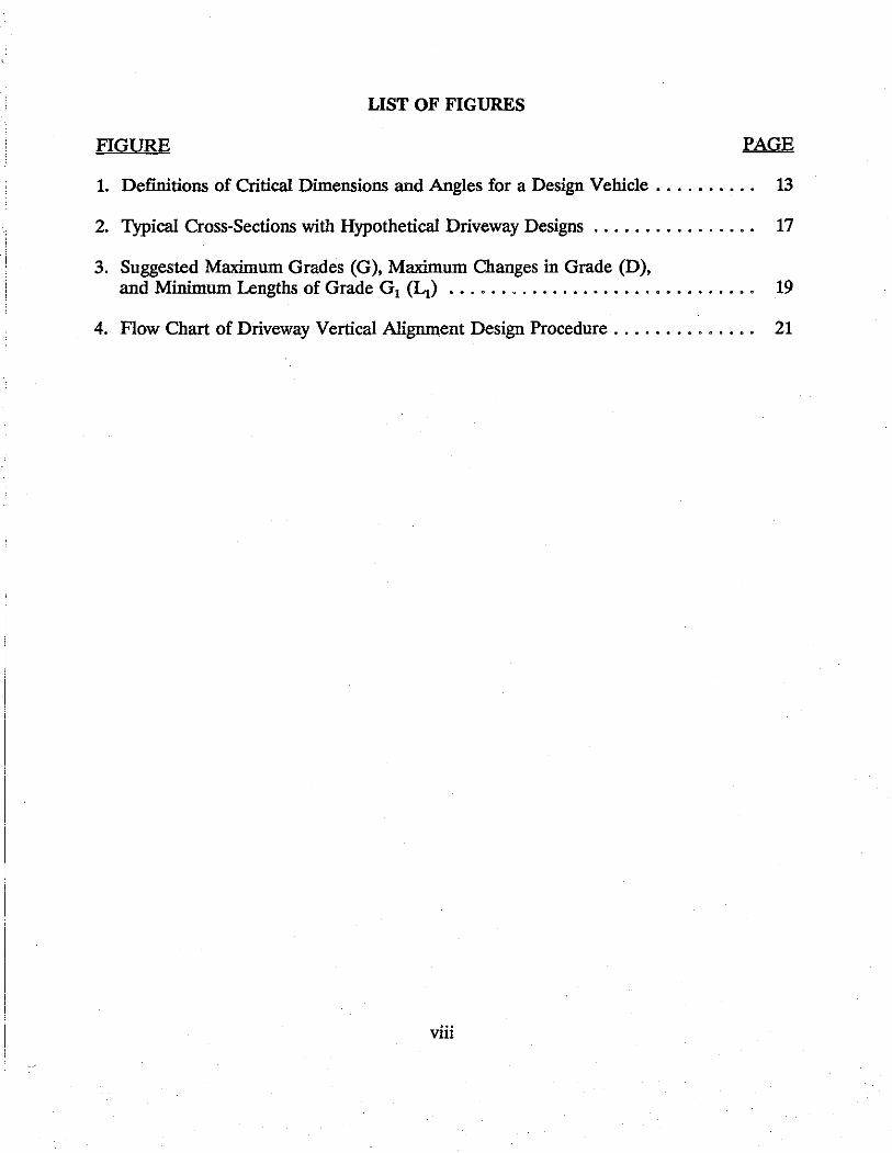
LIST OF FIGURES
FIGURE PAGE
1. Definitions of Critical Dimensions and Angles for a Design Vehicle . . . . . . . . . . 13
2. Typical Cross-Sections with Hypothetical Driveway Designs . . . . . . . . . . . . . . . . 17
3. Suggested Maximum Grades (G), Maximum Changes in Grade (D), and Minimum Lengths of Grade G1 (Li) . . . . . . . . . . . . . . . . . . . . . . . . . . . . . . 19
4. Flow Chart of Driveway Vertical Alignment Design Procedure . . . . . . . . . . . . . . 21
viii
1.0 INTRODUCTION
A number of roadway reconstruction and widening projects are planned for the near future in Texas. Many of these will result in a variety of driveway realignments. For these and other projects, there has been a demonstrated need for information regarding the vertical alignment of access driveways. Review of the available literature, however, indicates that there is little information on this subject.
The absence of specific guidelines results in a variety of problems associated with insufficient driveway vertical alignment. Typically, these problems are associated with physical, safety, and operational factors. Physical problems due to inadequate vertical alignment generally result in vehicles being unable to negotiate the driveway without coming into contact with the pavement surface. Drainage is an additional physical problem that can result from poor vertical alignment. Safety considerations are related to the speed differentials between vehicles entering and exiting the driveway and vehicles in the primary traffic lanes, as well as the available sight distance for vehicles exiting from the driveway. Operational problems are primarily associated with driver discomfort due to poor vertical alignment such as bumps, steep grades, and abrupt changes in grade. In some cases the vertical alignment makes it difficult, or even impossible, for the driver to maneuver through the driveway.
1.1 Problem Statement
The problems outlined above are especially pronounced for the two following conditions. The first case involves locations in hilly terrain where there is a limited amount of right-of-way available for situating the driveway. Examples of this first case often occur with roadway widening projects. The second case involves locations where special vehicles having restrictive characteristics must be accounted for in the design of the driveway. Examples of this second case are driveways to schools, access to residential subdivisions which must be used by buses, and driveways serving recreational areas that are frequented by large recreational vehicles. In these instances, as with other special design vehicle cases, the variety in wheel bases, underside clearances, operational performance, and other characteristics must be taken into consideration in the design of the driveway alignment.
In addition to the above cases, problems can also arise due to a variety of additional considerations. The type of driveway under design, whether it is residential or commercial, is an important consideration. Secondly, the functional classification and the traffic volume of the roadway from which the driveway is providing access is of concern in its design. Finally, the horizontal alignment of the roadway and the location of the driveway often combine to affect the vertical profile.
1
1.2 Objectives
The primary objective of this study is to establish preliminary design gnidelines for the vertical alignment of driveways. These guidelines are specifically developed for application in road reconstruction projects where the existing driveways must be realigned to account for a widened or realigned roadway.
The first task conducted as part of this research involved a review of the pertinent information regarding driveway design in publications and existing guidelines in use by state and local transportation agencies. The second task of research dealt with the evaluation of existing driveway designs through field surveys, construction plans, and operational observations. The third task was an evaluation of how the physical and operational characteristics of design vehicles should be included in the design procedure. The final task involved using the evaluations and comparisons of driveways and design vehicles to establish preliminary design guidelines for vertical alignment of access driveways.
This report provides an initial step in the development of a comprehensive set of controls for the geometric design of driveways. This report is a result of coordinated efforts between the Texas Transportation Institute (TTI) research team and Texas Department of Transportation (TxDOT) engineers.
1.3 Organization
This report is organized into five principal sections. The first section is the introduction, while the second section discusses classifications and definitions of terms used in the research and report. Section three is a compilation of design considerations which are to be used in establishing the final design guidelines. Section four outlines the design controls, established by this research, for the vertical alignment driveways. The fifth and final section consists of recommendations and conclusions pertaining to the design gnidelines.
In addition to the principal sections of this report, there are three separate appendices. Appendix A is a photographic compilation of examples of existing driveway designs. Appendix B presents a sample spreadsheet format that implements the design procedure of this report to evaluate the driveway problem in the previous appendix. Appendix C contains an example problem that is used to illustrate how the guidelines and procedures of this document can be applied.
2
2.0 GENERAL CONSIDERATIONS
When formulating the design of a driveway facility, there are a number of basic engineering considerations that should be kept in mind. Additionally, all designs should be evaluated with regard to safety and operational aspects. There are four principal concerns with unique characteristics and design considerations that driveway design should address: human factors, traffic considerations, physical elements, and economics. The following text discusses each of these principal considerations; however, it also should be noted that additional considerations can be made depending upon the unique characteristics of each particular location. In addition to these four considerations, a discussion is provided regarding how applications of agency regulations and minimum and desirable design guidelines can be understood.
2.1 Human Factors
Driver ability and driver comfort are two specific elements that should be regarded with respect to the vertical alignment design of a driveway. The expectancy of drivers, their decision-making ability, and their reaction times comprise the fundamental characteristics that define a driver's ability. Safety and operational aspects are highly related and strongly affected by driver ability. Adequate intersection sight distance and decision sight distance must be provided together with operational considerations such as the maneuverability of different vehicles and effective signs and markings.
The classification of the roadway facility (arterial, collector, and local) can influence the manner in which human factors considerations are applied in driveway design. For arterial streets and major collectors, traffic flow is of predominate concern over provisions for property access. Safety considerations are particularly critical with regard to vehicles interacting with the traffic stream. For minor collectors and local streets, property access becomes more prevalent, and traffic flow is reduced. Safety considerations with regard to pedestrians may become increasingly critical, while the majority of safety considerations associated with traffic stream interaction are less prevalent.
The comfort of the driver and occupants is an additional human factor concern that is specifically addressed by American Association of State Highway and Transportation Officials (AASHTO) with regard to vertical alignment. It is important that grades and rates of change of grades be kept within tolerable limits so that the combination of gravitational and centrifugal forces acting upon the driver and passengers are not excessive. The overall appearance of the facility to drivers approaching from all directions should also be considered as much as possible during the design process. Imposing grades and sudden profile breaks should be avoided.
3

2.2 Traffic Characteristics
For the design of a particular driveway, an assessment should be made of the traffic characteristics of both the street and the property served by the access driveway. Traffic characteristics will typically exhibit a high degree of variability with respect to the different functional and operational characteristics of specific locations. Elements that should be considered for each location are design volumes and speeds, allowable movements, vehicle types, and accident locations.
The design hourly volume and vehicular speeds for a driveway should be determined based upon traffic characteristics of the adjoining street and property. Driveway volumes can be predicted based upon analyses of the proposed site plan, similar traffic generators, and the directions of approach and departure of the expected clientele (i.e., a good Traffic Impact Analysis).
The movements that are allowed for both ingress to and egress from a property have a large effect on the desirable vertical alignment guidelines for the proposed driveways. Vehicular speeds and angles of approach as well as their effective turning radii should be taken into consideration in the design of each access location.
Accident location analysis for a particular driveway should be a post-design procedure that is done after the driveway is operational. If a particular driveway location has a history of being an accident location, an analysis of the conditions associated with the accident should be made and the factors contributing to the problem identified. It is good engineering practice, however, for the designer of a particular driveway to attempt to anticipate accident locations and to develop a design that would mitigate any problems prior to the actual design implementation.
2.3 Physical Elements
There are physical elements of the roadway and property that influence the design of the driveway. Primarily, geometric features are the key physical element to be considered, but such elements as traffic control, intersection location, lighting, and safety devices, along with features and characteristics of the abutting property, should also be considered.
Geometric features associated with the functional classification of the roadway are a primary concern in both the preliminary planning phase during which access rights are granted as well as during the design and implementation phases. It is desirable that the driveway design not fall below one functional classification of the roadway it is accessing. In other words, if a driveway is being designed to intersect an urban arterial, it should have geometric characteristics that are similar to those of a collector street. If a driveway is being
4

designed to intersect a collector, it should have geometric characteristics similar to those of residential street.
Additionally, with regard to geometric considerations, the location of turning lanes and median barriers is necessary to consider when determining vertical as well as horizontal profile. These items will affect the manner, particularly the speed and angles, that vehicles approach and leave the driveway. For instance, if a right-hand speed change lane is provided for vehicles wishing to tum into the property, it would be expected that the tendency would be for them to enter the driveway at a slow speed and with little distraction from other vehicles on the roadway. In general, the vertical profile of the driveway must allow drivers to make ingress and egress maneuvers to and from the property without creating safety or operational problems.
The location of intersections and, in particular, the functional boundaries of intersections should be considered in locating a driveway and in designing the driveway's geometries. AASHTO's 1984 edition of A Policy on Geometric Design of Highways and Streets (1) states on page 888 that "driveway terminals are in effect at-grade intersections and should be designed predicated on residential or commercial use, or both." Related to this design principle, the AASHTO policy goes on to state that "driveways should not be situated within the functional boundary of at-grade intersections."
Traffic control devices as well as lighting and other safety features have a range of influence on a driveway's vertical design. Driveway profiles should be such that traffic control devices along the roadway are readily visible for vehicles leaving the property. Lighting must be sufficient to allow drivers to safely locate the intersection, assess the geometry of the drive, and navigate their way into and out of the property. If location and design are unable to eliminate hazardous features, such as deep culverts or steep embankments, safety features must be provided to protect drivers. Numerous concerns associated with these elements can be determined for any particular case. These cases can include such things as access drives and tum-bays on horizontal curves or areas where rightof-way is severely restricted. Basic engineering judgement and design are the most important means of addressing these problems.
Vertical alignment of both the roadway and property are an obvious consideration in the profile design of the driveway. It is important that critical combinations of vertical alignment with other roadway or property features are noted, especially in instances where a driver's visual sight distance may be reduced or distracted. Attention should be given to approach and departure sight triangles. As is discussed on pages 727 and 774 in the AASHTO Policy on Geometric Design, "adequate sight triangles must be provided that are free of obstructions and will allow drivers to have a clear view of the driveway facility and the roadway" (1).
A final physical element that needs to be regarded is the character of the abutting property to which the access is being provided. The property's size and classification
5
(residential, commercial, industrial, etc.) will dictate the amount and characteristics of the traffic at the location. Hourly volumes and design vehicles will largely be influenced by the character of the property to which access is being provided.
2.4 Economic Factors
There are always economic factors that play a role in the design of a driveway intersection, and these often dictate the degree to which the property owner is willing to cooperate with design decisions. There are direct costs to be considered, such as the cost of the actual driveway or the cost to make improvements to the roadway, existing driveway, or abutting property. There are also indirect costs that must be considered, such as the effect that the driveway will have on the abutting property, vehicle fuel consumption and emissions, and delay incurred by motorists. A final economic consideration that is both a direct and indirect cost is associated with accidents that occur at the driveway location due to its design being below desirable limits.
2.5 Regulations
Any type of design should be done within the limitations of the regulations that apply to the particular project. The Texas Department of Transportation (TxDOT) has regulations which apply to driveway design (2). Regulations apply to such aspects as the type of driveway, access limitations, indemnification procedures, materials, inspection, etc. The regulations pertaining to construction and reconstruction are as follows:
"All new access driveways, following approval of permit, shall be constructed in conformance with the applicable regulations. Any existing access driveway structures which are destroyed or removed in the construction or reconstruction of a section of highway will be replaced or reconstructed by the Department to a qesign within these regulations and a condition equal to or better than the original structures."
2.6 Minimum vs. Desirable Desigu
TxDOT's Level II Design Manual provides a general discussion on engineering consideration that should be given toward "minimum" versus "desirable" standards (3.). This manual states that standards for design are often denoted in terms of "minimum" values. These values should be considered by the design engineer as the lowest acceptable limits in design. It is expected that designs will include the highest and most desirable standards that are possible while being commensurate with prevailing conditions. Some design values
6

may appear to be inviolable; however, these values are intended to be sufficiently flexible to permit designs to be tailored to unique situations.
Desirable values should be used generally and minimum values used only when unusual conditions are encountered. The closer design values are to desirable standards, the safer the driver environment will be and the better the capability of accommodating driver error.
The rehabilitation of existing highways often presents conditions that make it infeasible or non-cost-effective to acquire the right-of-way necessary to accommodate a desirable design. For these situations, consideration should be given to upgrading the driveway design to the maximum extent possible within the right-of-way such that it is able to adhere to the minimum guidelines.
In the event that minimum guidelines are not met, practical engineering judgement should be applied to find means of accommodating design deficiencies that may exist. The following list provides some examples of a few potential actions that could be taken to enhance driveway designs that may fall short of the minimum specifications:
1. Signing and pavement markings to warn motorists of potential bumps or steep grades;
2. Additional lighting to delineate the features of the driveway at night;
3. Traffic control devices to accommodate for restricted sight distances or partial "blind spots"; and/ or
4. Multiple grades to provide for less severe changes in grades.
7

8

3.0 SPECIFIC DESIGN ELEMENTS
The following list of specific design elements applies to the basic design procedure outlined in this report. The elements discussed in this section are primarily functional criteria that must be considered in practical engineering design.
3.1 Area Type
A region's area type is determined by the density and types of land use, the density of street and highway networks, the nature of travel patterns, and the way these elements are interrelated. There are three common classifications of area type:
Rural - An area in which the adjacent properties are agricultural in nature and there is no current potential for non-agricultural development. Driveways are infrequent and are subject to very low traffic (typically less than 15 vehicles per day).
For driveways constructed in rural areas, it is common practice to have the initial grade of the driveway tie into the shoulder slope of the roadway. In other words, the driveway's first grade and the highway's shoulder slope should be the same. This grade should continue for the entire shoulder width or longer. This feature is primarily provided for safety considerations so as not to cause a hump or depression in the shoulder area that is commonly used by highway traffic (~).
Urban - An area in which residential, commercial, and industrial land uses predominate, or an area which is developed, or is expected to be developed, in such use within the next 5 years, or the horizon of the municipal capital improvement program, whichever is longer.
Driveways constructed in urban areas should accommodate the existing curb and gutter section of the roadway as well as sidewalks and drainage requirements. For the construction of driveways at high volume locations, such as commercial and industrial locations, the height of the curb transitions to zero and the gutter is carried through the driveway to avoid accident hazards or driver discomforts. For residential driveways along local streets, mountable curbs can be used as long as the curb is lowered to approximately the same elevation as that of the gutter. At high volume locations with sidewalks situated near the curb line, a depression in the sidewalk should be provided along the driveway section. By warping the sidewalk to conform with the profile of the driveway, undue inconsistency in the driveway's grade can be avoided. Locations carrying drainage along the curb should have
9

driveway grades constructed so that runoff is prevented from spilling onto the private property (2).
Urban Fringe - An area which is undergoing a transition to non-agricultural uses or which may be subjected to such transition within the next several years. Additionally, property within the extraterritorial jurisdiction of a municipality should be considered as urban fringe.
Driveways constructed in urban fringe areas constitute a mix of requirements in their design that is drawn from rural and urban design requirements. Generally the design cross-section is rural in nature while the operational considerations are urban in nature.
3.2 Driveway Classification
A driveway is a point of access connecting an adjacent property to the public roadway. The AASHTO Policy on Geometric Design states that "the principles of intersection design should apply to driveway design" (1).
Driveway design is dependent upon the functional classification of the driveway, which is determined from the land use requirements of the property the driveway is serving. There are four general types of land uses, or property types, which driveways can serve (5.):
Private (Residential) - One providing access to a single family residence, to a duplex, to an apartment building containing not more than 4 units, or to a farm or ranch.
Public - One providing access to a school, church or other public place. This type of driveway can often be used by special types of vehicles such as school busses requiring special design considerations.
Commercial - One providing access to an office, retail, or institutional building, or to an apartment building having five or more dwelling units. Such buildings are customarily serviced by trucks as an incidental rather than a principal driveway use.
Industrial - One directly serving a substantial number of trucks such as an industrial warehouse or truck terminal. A large regional shopping center may have one or more driveways that are specially designed to provide access for large trucks servicing the center; such driveways are classified as "industrial" (2).
10

3.3 Streets and Highways
AASHTO specifically states that roadway design should be based upon the function of the roadway as opposed to basing the design on the roadway's volume. Streets and highway segments commonly provide two distinct functions: movement of vehicles (or, if movement is acceptable, mobility) and access to land or property. The manner in which a roadway segment handles these functions defines the segment's functional classification.
The following are three broad functional classifications into which streets can be categorized (n):
Arterials - Urban facilities that provide a high degree of mobility over long distances. Arterials are continuous roadways designed to accommodate movement. Access is provided but not to the extent that the access function interferes with the movement function. Ordinances typically prohibit certain types of access, such as local streets and minor driveways, to an arterial street. These restrictions of access help to reduce excessive interference to the traffic stream by turning movements, thereby increasing safety and operating speeds.
Arterials can be classified as either major or minor arterials according to the degree to which they provide vehicular movement. Freeways are considered to be high-level arterials since their function is to provide movement. Freeways are differentiated from major arterials by the design of access which is provided by grade separated interchanges.
Collectors - Intermediate facilities that are a grade below the arterial facilities. Collectors provide a higher degree of property access than do arterials; movement along the street is more restrictive and discontinuous. Like arterials, collector streets are subclassified as major and minor.
Locals - Minor facilities that predominately serve the function of providing access to property. To accomplish this access function, movement is restricted with short, discontinuous street segments so as to result in slow operating speeds and low traffic volumes.
A functionally designed transportation system should recognize that driveways create intersections with the roadways from which they provide access, and design controls should be accordingly developed to minimize the potential for conflict.
11

3.4 Design Vehicle
With regard to driveway design, a design vehicle is a specific vehicle whose physical dimensions and operational characteristics are more restrictive than those found on other vehicles. An assessment of the types of vehicles that are expected to use a particular driveway should yield the physical dimensions and operational characteristics that are necessary to establish a design vehicle for the driveway.
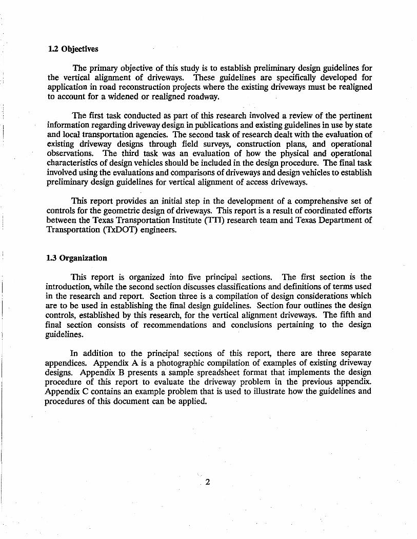
The physical dimensions of the design vehicles will be needed to determine the guidelines for grade changes. Critical dimensions of a design vehicle include lengths and clearances for the front, rear, and wheelbase. Critical angles can be determined from these dimensions and include approach and departure angles, used to determine the critical sag grade breaks, and cross-over angles, used to determine the critical crest grade breaks. Each of these dimensions and angles are illustrated in Figure 1.
12

1r-~ !'-'-Ji __.~.____.!._____.
Front Clearance
t Base Clearance
Rear-11*+--Wheelbase ---11~4-Front--i..i
Design Vehicle - Critical Dimensions
i-Wheelbase
Design Vehicle - Critical Angles
Figure 1. Definitions of Critical Dimensions and Angles for a Design Vehicle.
13

14

4.0 RECOMMENDED GUIDELINES
In developing design guidelines for vertical alignment of a particular driveway, the physical components of both the vehicle and the driveway must be coordinated and evaluated in order to develop the critical design dimensions. The physical components include the maximum and minimum grades, lengths of grades, and the critical angles of approach, departure, and cross-over. The following procedure provides a recommended framework for formulating the vertical alignment dimensions of a driveway based upon these characteristics.
The design of adequate driveway grades should be developed with respect to three primary factors. These are site characteristics, functional requirements, and design vehicles. Requirements for maximum and minimum grades and lengths of grades are established based upon the site characteristics and functional requirements of the driveway. Site characteristics are broad considerations that incorporate elements discussed in Section .2 while functional requirements are specific considerations that incorporate elements discussed in Section 3. Design vehicle dimensions are necessary for determining whether or not the driveway profile will provide adequate clearance between the vehicle and the driveway surface, and these dimensions were also discussed in Section 3.
4.1 Existing Site Dimensions
To begin a design formulation, an assessment of the existing conditions at the site should be made. Specific elements that can be evaluated are available right-of-way, roadway and property elevations, roadway cross-slope, shoulder slope, and property slope.
Available right-of-way - The amount of available right-of-way will dictate the maximum length of the driveway that can be constructed without requiring the acquisition of additional right-of-way or a property easement. This distance is measured from the edge of the roadway to the existing right-of-way/property line.
Roadway and property elevations - The relative difference in the vertical elevation between the roadway edge and the property line should be established. The roadway edge elevation is measured from the point at which the driveway will begin, typically the pavement edge or, if one is present, the shoulder. The property elevation is measured from the point at which the driveway will terminate, typically the right-of-way or easement limit.
Roadway cross-slope - The cross-slope of the roadway and/or shoulders is necessary for determining the angle of grade-break between the roadway and the initial slope of the driveway.
15

Shoulder slope - On uncurbed sections of highway, the grade of the driveway should conform to the normal shoulder slope from the edge of the travelled way to the outer shoulder line. In other words, the shoulder of a roadway will constitute the initial portion of the driveway's first grade.
Property slope - If the slope of the property that the driveway is providing access to is extreme enough to cause a severe grade-break angle between itself and the roadway, it may need to be evaluated and modified. The angle of grade-break between the final slope of the driveway and the property may present itself as a critical design factor.
Figure 2 illustrates typical cross-sections for two hypothetical driveway design situations. The primary driveway and site dimensions are labeled on each example. The first pair of driveways are illustrative of the types of design that could occur in urban locations on roadway cross-sections with curbs and gutters. For these situations, the first driveway grade (G1) will originate at the pavement edge where the curb and gutter section is modified or removed. The right-of-way will be located on or near the end of the second grade (G2). Due to drainage requirements, G1 is almost always a positive slope. The presence of sidewalks or unusual drainage considerations, however, could alter these general examples of urban cross-sections.
The second pair of driveways in Figure 2 are illustrative of the types of design that could occur in rural locations on roadway cross-sections with shoulders. For these situations, the first grade (G1) will originate at the pavement edge and must conform to the slope of the shoulder, generally resulting in G1 having a negative slope. The right-of-way will be located on or near the end of the second grade (G2). Superelevated roadway sections or drainage considerations could alter these general examples of rural crosssections.
4.2 Design Considerations
Driveways should conform to specifications that are derived based upon the driveway location's area type (Section 3.1) along with the functional classification of the driveway (Section 3.2) and adjacent roadway (Section 3.3). Additional considerations could be based upon those elements addressed in the previous section (4.1). These elements include the presence of curbs and gutters, shoulders, sidewalks, superelevated sections, and drainage factors. The examples that were presented in Figure 2 can be considered as basic representations of the driveway designs for urban and rural situations respectively.
This document is not of the scope to which all combinations of vertical alignment can be effectively addressed. Combinations of multiple design elements could alter the alignment beyond the four basic examples that are presented. It is up to the design engineer to evaluate and refine each design once the basic guidelines have been either met or addressed. For some instances, deviation from these guidelines may be acceptable, but practical engineering judgement should be used to validate decisions in this regard.
16

Pavement R.0.W. Elevation Property
_t Elevation
.. G1 (+) G.!<-l i -
k- L1 >I !IE: L2 >I
R.0.W. Property
I Elevation Pavement i Elevation
G.!(+)
J = G1 (+)
~ ~ L1 >I< L2
Typical Urban Driveway Design (On Cross-Sections with Curb and Gutter)
Pavement Elevation Shoulder
* I G1 (-).
k- L1 >I<
Pavement Elevation Shoulder
t I "1 (-)
R.0.W.
I
G.! (-) I
L2 >I
R.0.W. I
G.!(+)
Property Elevation
t
Property Elevation
t
Typical Rural Driveway Design (On Cross-Sections with Shoulders)
Fignre 2. Typical Cross-Sections with Hypothetical Driveway Designs.
17

4.3 Maximum Grades and Grade Changes
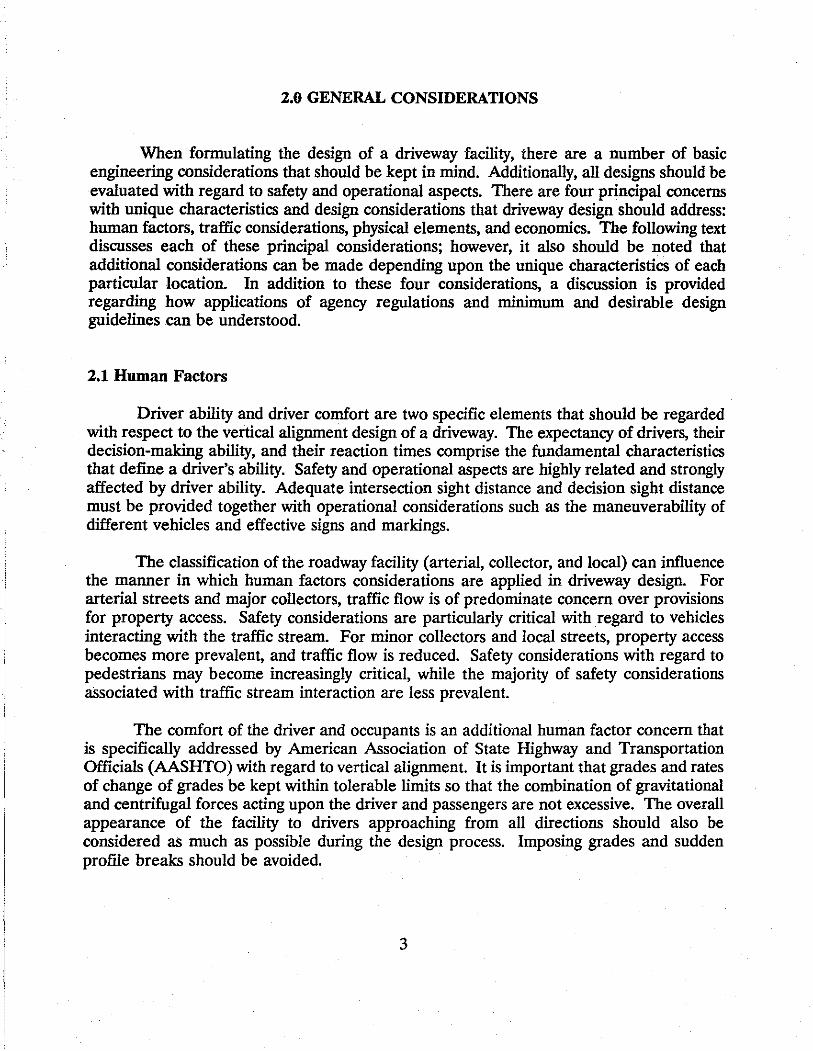
A Federal Highway Administration (FHWA) publication, Access Management for Streets and Highways, provides some fundamental guidelines for the establishment of maximum grades for driveways (~). Figure 3 is derived from the FHW A publication .and provides an illustration of a typical driveway profile along with a table of maximum grades and grade changes for various driveway classifications and volumes.
These maximum values are essentially minimum design guidelines and were established due to operational and safety problems that can occur when grades and grade changes are excessive. Steep grades inhibit the performance characteristics of vehicles, especially braking and acceleration. Additionally, vehicle operators are often unable to judge necessary stopping and acceleration distances that are associated with steep grades. Grade changes also present operational problems if the change is so abrupt that adequate vehicular clearance is not available. Safety problems can be a concern when poor sight distances result from sharp grade changes.
4.4 Vertical Curves
For extreme grade changes, especially those in excess of the maximum values listed in Figure 3, vertical curves should be constructed to allow for improved operations and safety. Vertical curve design for driveways should follow the same requirements used for vertical curves on streets and highways. Designers should consult applicable manuals such as TxDOT's Highway Design Division Operations and Procedures Manual (1) or Chapter 3 of the AASHTO Policy on Geometric Design (1).
The minimum design length of vertical curves, as stated by AASHTO is 20 feet. For some instances, however, this minimum length may be to long for driveway design. In some cases, the available right of way is not much more than 20 feet. For these instances, the designer should utilize multiple grades or simply accept the short vertical curve. Consideration should be given to the placement of the vertical curve to minimize any operational hazards that may exist. It may also be appropriate to provide signing to warn drivers of possible dips or bumps.
A slight degree of vertical curvature usually occurs when concrete or seal coat is poured over grade breaks. In some instances this feature could provide enough vertical curvature to smooth in excessive transitions.
18

Edge of
#Pavement
I I
High Volume (Commercial, Industrial) Low Volume (Commercial, Industrial) Residential
0.
3-±3% ±5% ±8%
02 ±5% ±8% ±15%
D, orD2
±3% ±6%
Yeh. Clear.
*L1 (ft.)
40 40 10
* For driveways with restrictive sight distances, it is often desirable to have L1 equal to the maximum length of the design vehicle but not less than the values indicated in the table. For certain combinations of grades where no sight distance geometric or operational constraints exist, it may be possible to justify values ofL1 that are less than those in the table.
Figure 3. Suggested Maximum Grades (G), Maximum Changes in Grade (D), and Minimum Lengths of Grade G1 (L1).
19

4.5 Design Procedure
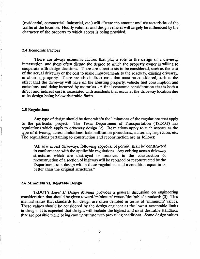
The following items illustrate some of the specific considerations that are necessary for formulating an initial driveway design. For each design element under consideration (slopes, grade changes, etc.), the initial design should be formulated within the maximum/minimum guidelines outlined in this section. Once the initial design has been established with respect to the maximum/minimum guidelines and right-of-way constraints, it should be tested to ensure that it can accommodate the design vehicles proposed for the driveway. IT the driveway fails to provide adequate clearance for the design vehicle, alignment modifications will be necessary. Once these modifications are complete, the design should again be compared to the maximum/minimum guidelines to ensure that it is adequate. Figure 4 provides a general flow chart for this procedure.
There are six primary components of a driveway that should be considered in the formulation of the general design. These components are the slope and lengths of the driveway grades along with the grade break angles formed by the driveway's grade changes. Each of these components are discussed below along with considerations that are necessary to develop a desirable design. For minimum design, specific driveway components should at least conform to the guidelines that were listed in Figure 3.
Slope of Grade 1 (G1) - This grade is to allow vehicles exiting a roadway to do so without immediately climbing or descending, to allow vehicles entering the roadway to have a waiting area at approximately roadway level, and to provide for the drainage considerations previously discussed in this section. For urban locations the value of G1 is restricted by the presence of a sidewalk and generally should be positive to allow the driveway to initially slope upward away from the gutter. For rural locations the slope of G1 is generally limited by the shoulder slopes, primarily for safety considerations (;!).
Grade Break Angle 1 (D1) - This grade break angle is defined by the cross-slope of the roadway and the slope of G1• For the majority of cases in urban or suburban locations, D1 will be positive and should fall within the critical approach/departure angles of the design vehicles. For many driveways in rural locations D1 will be negative. For this case, D 1 should not be greater than the critical cross-over angles of the design vehicles. In situations where D1 is in excess of the maximum values listed in Figure 3, vertical curves should be incorporated as discussed in Section 4.3.
Length of Grade 1 (L1) - In general, the length of this first grade must be sufficient to accommodate the functional requirements of the driveway. As a minimum design, Li should be at least equal to the maximum length of a design vehicle but not less than 10 feet for residential driveways or 40 feet for most commercial and industrial driveways. Latitude may be given to certain commercial and industrial locations if it is determined that the types of trucks entering the driveway can be accommodated with grade lengths shorter than 40 feet or the occurrence of a large truck entering the driveway is infrequent. A level "landing"
20
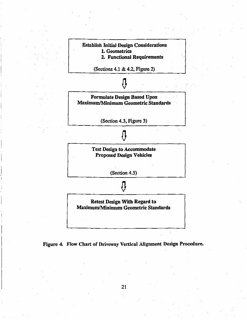
Establish Initial Design Considerations 1. Geometrics 2. Functional Requirements
(Sections 4.1 & 4.2, Figure 2)
Formulate Design Based Upon Maximum/Minimum Geometric Standards
(Section 4.3, Figure 3)
Test Design to Accommodate Proposed Design Vehicles
(Section 4.5)
Retest Design With Regard to Maximum/Minimum Geometric Standards
Figure 4. Flow Chart of Driveway Vertical Alignment Design Procedure.
21

area should be considered at the driveway's approach to the street in order to provide adequate sight distance and a smooth transition area.
Slope of Grade 2 (GJ - This grade, for the majority of instances, provides the major transition in elevations for the driveway. Desirable design of G2 should incorporate functional and safety considerations as has been previously discussed throughout this report. Some governmental jurisdictions have restrictions on storm water run-off or other types of site drainage leaving the property and entering the public right-of-way. In these case G2 should be designed to control drainage and keep it on the property.
Grade Break Angle 2 (D2) - This grade break angle is defined by the difference between the slope of G1 and the slope of G2• For cases where D2 is positive, it should fall within the critical approach/departure angles of the.design vehicles. If D2 is negative, it should not be greater than the critical cross-over angles of the design vehicles.
Length of Grade 2 (Lz) - There are no specific limitations on the length of the second grade, but in general, L:z should extend for as long as is practically feasible to minimize the slope of this grade. In areas with restricted right-of-way, it may be necessary to acquire additional right-of-way or relocate the driveway to provide for a sufficient length of Li and minimize the driveway's second grade.
22

5.0 SUMMARY
The guidelines for formulating the vertical alignment of driveways presented in Section 4 are intended to provide a procedural framework by which driveways can be designed and/or analyzed. The values presented for grades and grade changes are design minimums for those individual elements. Combinations of certain values for individual elements may create conditions for particular types of design vehicles that do not meet the guidelines of this report. Each proposed grade combination should be evaluated with respect to specific vehicular clearance capabilities.
5.1 Conclusions
It is desirable that the grades and grade changes be minimized to the greatest extent possible during the design process. These minimum guidelines should be implemented provided that conditions exist that allow for the guidelines to be accommodated in a practical manner. In contrast, if conditions exist that make meeting the minimum design guidelines unduly expensive or impractical, design adjustments should be made utilizing engineering judgement to ensure that the design is safe and accessible.
5.2 Recommendations
Design Applications - This report can be used to provide general guidelines in the design and evaluation of driveways. Suggested minimum design values are provided for different driveway uses and include such features as grades, lengths of grades, and changes in grades. Desirable design values should correspond with the design principals for intersections that are stated in AASHTO's Policy on Geometric Design (1). Because of the diversity and range of driveway designs, the design values recommended in this report should not circumvent the judgement of the engineer or designer.
Computer/Spreadsheet Applications -The procedural framework presented in these guidelines is such that computer methods can be incorporated into the design process. Basic computer programming or spreadsheet applications can be particularly useful when multiple designs are to be analyzed. Appendix B presents an example of a spreadsheet program that utilizes the guidelines and procedures outlined in this document for some specific applications.
Appendix C provides a sample design problem in which the guidelines of this report are utilized to evaluate the proposed design for a driveway. The guidelines are followed in the preliminary design of the driveway as well as the corresponding analysis of specified design vehicles. The minimum requirements for grade and grade changes developed from these guidelines are presented once the preliminary design has been formulated.
23

24

6.0 REFERENCES
1. American Association of State Highway Transportation Officials. A Policy on Geometric Design of Highways and Streets. Washington DC: AASHTO, 1984.
2. Regulations for Access Driveways to State Highways. Prepared by the Safety and Maintenance Operations Division of the Texas Department of Transportation. Austin, TX: The State of Texas, August 1986.
3. Design Training Manua~ Level JI, "Roadway Design, Subject 7." Texas Department of Transportation. Austin, TX: The State of Texas, 1988.
4. Access Management for Streets and Highways. Federal Highway Administration. Washington DC: U.S. Department of Transportation, June 1982.
5. Institute of Transportation Engineers. Guidelines for Driveway Design and Location. Washington DC: ITE, 1974.
6. Stover, V.G. and Koepke, F.J. "Functional Circulation Systems," Chapter 4. Transportation and Land Development. Institute of Transportation Engineers. Englewood Cliffs, NJ: Prentice Hall, 1988.
7. Highway Design Division Operations and Procedures Manual Texas Department of Transportation. Austin, TX: The State of Texas, Revised February 1987.
25

26

APPENDIX A • Examples of Existing Driveway Designs
27

28

Figure A-1. The widening of a rural highway has produced a driveway with a severe grade. Driver attention is focused on the driveway rather than the highway, and multiple hazards are presented for entering and exiting vehicles. Deep scrape marks exist in the pavement from impacts with vehicle bumpers and under-carriages. (G, =2%, L1 =34 ft., G2 =22%, L,=65 ft.)
Figure A-2. This relatively high volume driveway provides access to a commercial shopping center alongside an urban curb and gutter roadway section. The initial grade is severe and could cause discomfort to entering and exiting motorists. Multiple scrape marks indicate that the grade breaks also are severe. (01 =16%, L1=62 ft., 0 2 =-2%, L,=10 ft.)
29

Figure A-3. Multiple grades can result in sharp grade breaks and inadequate lengths of grades. This driveway, which connects a small commercial facility to a minor collector, could be redesigned with two longer, less severe grades to allow for smoother transitions. (G1=9%, L1 =7 ft., G2 =1%, L2 =7 ft., G,=-19%, L,=23 ft.)
Figure A-4. The initial grade of this driveway may be too short to accommodate a high volume of large trucks; note, however, that the first grade corresponds to the shoulder's slope and continues for several feet beyond the shoulder's edge. The driveway's second grade is severe and may limit the sight distance of drivers attempting to exit from the property. (G1 =4.5%, L1 =20 ft., G2 =-16%, L2 =50 ft.)
30

Figure A-5. The first grade descending from the minor arterial is of adequate length, but the slope may be inappropriate for high volume commercial operations. (G1 =-4%, L1 =50 ft.)
Figure A-6. Long grades and relatively minor changes in grades are characteristics of good design. The dimensions for this driveway are acceptable for commercial operations with low to moderate volumes. Unfortunately, the trees may interfere with adequate sight distance. (G1 =1.5%, L1 =45 ft., G2 =-3%, L2 =45 ft.)
31
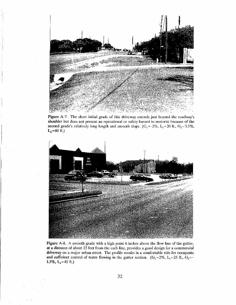
Figure A-7. The short initial grade of this driveway extends just beyond the roadway's shoulder but does not present an operational or safety hazard to motorist because of the second grade's relatively long length and smooth slope. (G 1 ~ -2%, L1 ~20 ft., G,~ 3.5%, L2 =60 ft.)
Figure A-8. A smooth grade with a high point 6 inches above the flow line of the gutter, at a distance of about 25 feet from the curb line, provides a good design for a commercial driveway on a major urban street. The profile results in a comfortable ride for occupants and sufficient control of water flowing in the gutter section. (G1 ~2%, L1 =25 ft., G,=-1.5%, L2 =45 ft.)
32
APPENDIX B - Example Spreadsheet Formulation
33

34

SPECIFIC INSTRUCTIONS FOR DATA INPUT AND OUTPUT
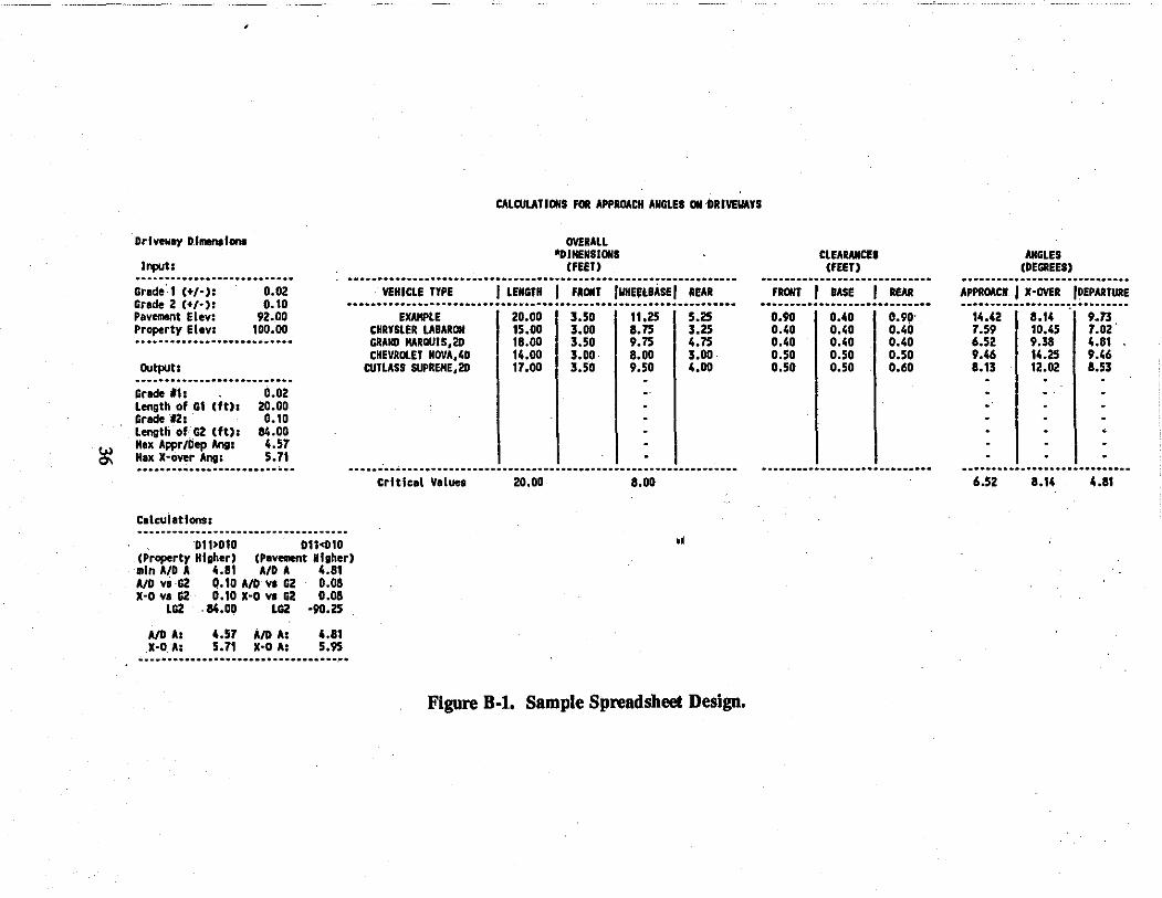
The following are some basic instructions for using the spreadsheet formulated for application with the design problem that is presented in Appendix C. Figure B-1 provides an illustration of the spreadsheet discussed in this appendix.
DRIVEWAY DIMENSIONS
Input Values: Grade 1 (+/-) - Enter the grade (as a decimal) that is nearest the roadway. This number is called G1 in the spreadsheet.
Grade 2 ( + /-) - Enter the grade (as a decimal) that is nearest the adjacent property. This number can be either positive or negative, so it is important to enter the correct sign for this grade. This number will be called G2 in the spreadsheet.
Pavement Elev. - The value entered here (in feet) may or may not be the actual elevation. Only the relative difference (in feet) between the pavement elevation and the property elevation will matter.
Property Elev. - Again, this value (in feet) is only relative to the pavement elevation.
Output Values: Grade 1- This cell displays the calculated maximum acceptable grade for G1 (as a decimal). If the entered design value is acceptable, then this output value will be equal to the value for G1 that was entered by the user. If the entered design value is not feasible, then the cell will indicate the maximum acceptable value that it has computed.
Length of G1 (ft.) - This cell displays the calculated minimum length (in feet) along the G1 grade that must exist for the Grade 1 value given above. Typically this value is based on the maximum design vehicle length.
Grade 2 - This cell displays the calculated maximum value that G2 can assume (as a decimal). As long as the design values entered are feasible, this value will be the entered value of G2•
Length of G2 (ft.) - This cell displays the calculated minimum length (in feet) along the G2 grade that can be used given the value of G1•
Max Appr /Dep Angle - This cell displays the calculated maximum approach/ departure angle (in degrees) that can be attained using the computed values for G1 and G2•
Max X-Over Angle -This cell displays the calculated maximum cross-over angle (in degrees) that can be attained using the computed values for G1 and G2•
35
Driveway Dlmenolons
ll'f>Utl
Grodo·I <•I·>• 0.02 Grode 2 (+/·): 0.10 Pavement Elev: 92.00 Property Elev: 100.00
output:
Grode #1: length of GI Cftl: Grade 12: length of G2 <ft): Hex Appr/Dep Ang: Max X·over Ang:
0.02 20.00 o. 10
84.00 4.57 5.71
----·····----·····-····-··-
Calculations:
Dl1>D10 011<010 (Property Higher) (Povetnent Higher) min A/D A 4.81 AID A 4.81 A/0 vi·G2 Q.10 A/D VI G2 0.08 X·O YI G2 0.10 X·O VI G2 0.08
LG2 .114.00 LG2 ·90.25
AID Al X·O A:
4.57 AID A: 5.71 X·O A:
4.81 5.95 .... -............................................................ ..
CALCULATIONS FOR APPROACH ANGLES OH DRIVEWAYS
VEHICLE TYPE
EXAMPLE CHRYSLER LABAROll GRAND HARQUJS,20 CHEVROLET NOVA,40
CUTLASS SuPREHE,20
Crltlcol Volues
OVERALL "DIHENSIOllS
(FEET>
I LENGTH I FRONT fllHEELBASEf REAR
20.00 15.00 18.00 14.00 17.00
20.00
3.50 3.00 3.50 3.00 3.50
11.25 8.75 9.75 8.oo 9.50
8.oo
••
5.25 3.25 4.75 3.00 4.00
Figure B-1. Sample Spreadsheet Design.
CLEARANCES <FEET)
.....................................................
FRONT I BASE I REAR -----------------------------0.90 0.40 0.90·
0.40 0.40 0.40 0.40 0.40 0.40 0.50 0.50 0.50 0.50 0.50 0.60
ANGLES (DEGREES) .. ................................................
APPROACH I X·OVER fDEPARTURE ..................................................
14.42 8.14 9.73 7.59 10.45 7.02. 6.52 9.38 4.81 9.46 14.25 9.46 8.13 12.02 8.53
.·
6.52 8.14 4.81

OVERALL VEHICLE DIMENSIONS
Vehicle Type - This field is simply a label area for the convenience of the user to identify the types of design vehicles that are being evaluated.
Length - Total bumper-to-bumper length of the vehicle, in feet ..
Front - Length, in feet, from the front edge of the vehicles' front bumper to the center of its front axle.
Wheelbase - Distance, in feet, from center of the vehicles' front axle to center of its rear axle.
Rear - Distance, in feet, from center of the vehicles' rear axle to the edge of the rear bumper. (Exceptions should be made where high proportions of vehicles with trailer hitches occur. In these cases, the rear distance should be out to the edge of the trailer hitch or the furthest extensions from the vehicle.)
CLEARANCE
Front - Vertical height, in feet, between pavement surface and low point edge of the front of the vehicle.
Base - Vertical height, in feet, between pavement and vehicles' underside clearance between the two axles.
Rear - Vertical height, in feet, between pavement and low point at rear of vehicle. This height will probably involve the muffler, if there is one.
ANGLES
Approach, X-Over, Departure - No values are entered in these cells. The cells contain the calculated values for the respective angles for each of the design vehicles. The worst-case values for each of the three types of angles will be taken as the design values.
37

USING THE DRIVEWAY SPREADSHEET - STEPS TO FOLWW
1. Enter the values required to complete the driveway dimensions - input section of the spreadsheet. These values include grade 1, grade 2, pavement elevation, and property elevation. These values are explained in the section which gives specific instructions on what should be entered in each cell.
2. The user should enter data into the section on design vehicles - overall dimensions and clearance. Again, for a description of what exactly needs to be entered in each particular cell, reference can be made to the instructions. The user can enter up to twelve (12) design vehicles in this region. Note that the program automatically selects the most critical values for the analysis of the vehicle dimensions. These critical values appear below the dimensions data area.
3. The user needs to input the respective dimensions of the design vehicles, including length, front, and rear. Note that the wheelbase is a calculated value. The user only need enter the length, front, and rear measurements. Again, the critical values are tabulated at the bottom of the data entry area.
4. The ground clearances for the respective design vehicles can be entered, including front, base, and rear. Critical values are calculated and shown as in the previous data entry areas.
5. The spreadsheet will now take over with the analysis. In the angles section, the program calculates the critical approach and cross-over angles for each design vehicle, given the dimensions entered by the user. As with the dimensions, the program selects the most critical values for the analysis and indicates them in the critical values area.
6. In the driveway dimensions - output section, the program calculates the values that can be used for the design. The way that each of these values is calculated is explained in more detail in the instruction section.
7. The calculations section is simply an area used by the spreadsheet to make some of the required computations. No values are required to be entered into this area, nor should any concern arise if the values do not appear familiar.
NOTE: This spreadsheet is presented as an example of a possible application of the methodology outlined in this document. It is not an acceptable substitute for following the methodology itself. The spreadsheet was designed for application to a few specific cases and not for all possible types of driveway designs. ·
38
APPENDIX C • Example Driveway Problem
39

40
EXAMPLE DRIVEWAY PROBLEM
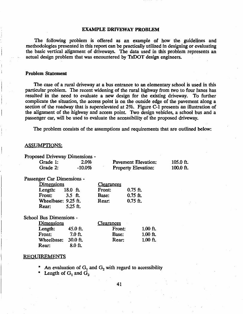
The following problem is offered as an example of how the guidelines and methodologies presented in this report can be practically utilized in designing or evaluating the basic vertical alignment of driveways. The data used in this problem represents an actual design problem that was encountered by TxDOT design engineers.
Problem Statement
The case of a rural driveway at a bus· entrance to an elementary school is used in this particular problem. The recent widening of the rural highway from two to four lanes has resulted in the need to evaluate a new design for the existing driveway. To further complicate the situation, the access point is on the outside edge of the pavement along a section of the roadway that is superelevated at 2%. Figure C-1 presents an illustration of the alignment of the highway and access point. Two design vehicles, a school bus and a passenger car, will be used to evaluate the accessibility of the proposed driveway.
The problem consists of the assumptions and requirements that are outlined below:
ASSUMPTIONS:
Proposed Driveway Dimensions -Grade 1: 2.0% Grade 2: -10.0%
Passenger Car Dimensions -Dimensions Length: 18.0 ft. Front: 3.5 ft. Wheelbase: 9.25 ft. Rear: 5.25 ft.
School Bus Dimensions -Dimensions Length: Front: Wheelbase: Rear:
REQUIREMENTS
45.0 ft. 7.0 ft.
30.0 ft. 8.0 ft.
Pavement Elevation: Property Elevation:
Oearances Front: Base: Rear:
Oearances Front: Base: Rear:
0.75 ft. 0.75 ft. 0.75 ft.
1.00 ft. 1.00 ft. 1.00 ft.
* An evaluation of G1 and G2 with regard to accessibility * Length of G 1 and G2
41
105.0 ft. 100.0 ft.

Pavement Elevation= 105 ft.
! G,-2.0%
Property Elevation= 100 ft.
Figure C-1. Vertical Alignment for the Example Problem's Driveway Section.
42
Solution
The spreadsheet presented in Appendix B is utilized for determining a possible combination of grades for an appropriate driveway design. The assumptions for this problem were entered into the appropriate spreadsheet fields as is illustrated in Figure C-2.
For each of the two design vehicles, the angles of approach, cross-over, and departure were calculated. These angles were compared and the critical values were determined for each of the two design vehicles along with the critical length and wheelbase for the vehicle. For each of these five requirements, the critical design values of the school bus were more critical than those for an ordinary passenger car.
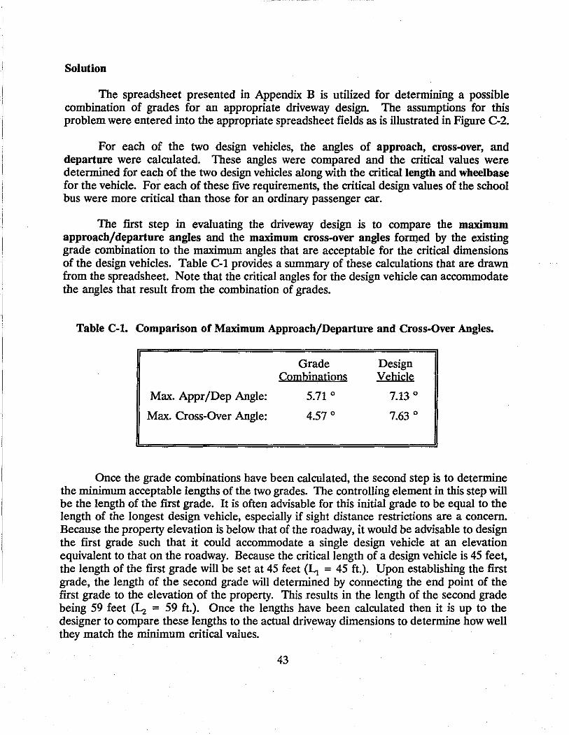
The first step in evaluating the driveway design is to compare the maximum approach/departure angles and the maximum cross-over angles fo~ed by the existing grade combination to the maximum angles that are acceptable for the critical dimensions of the design vehicles. Table C-1 provides a summary of these calculations that are drawn · from the spreadsheet. Note that the critical angles for the design vehicle can accommodate the angles that result from the combination of grades.
Table C-1. Comparison of Maximum Approach/Departure and Cross-Over Angles.
Max. Appr/Dep Angle:
Max. Cross-Over Angle:
Grade Combinations
5.71 ° 4.57 °
Design Vehicle
7.13 ° 7.63 °
Once the grade combinations have been calculated, the second step is to determine the minimum acceptable lengths of the two grades. The controlling element in this step will be the length of the first grade. It is often advisable for this initial grade to be equal to the length of the longest design vehicle, especially if sight distance restrictions are a concern. Because the property elevation is below that of the roadway, it would be advisable to design the first grade such that it could accommodate a single design vehicle at an elevation equivalent to that on the roadway. Because the critical length of a design vehicle is 45 feet, the length of the first grade will be set at 45 feet (Li = 45 ft.). Upon establishing the first grade, the length of the second grade will determined by connecting the end point of the first grade to the elevation of the property. This results in the length of the second grade being 59 feet (1..-i = 59 ft.). Once the lengths have been calculated then it is up to the designer to compare these lengths to the actual driveway dimensions to determine how well they match the minimum critical values.
43

---------------~-----------·----··------- --- -- --
Driveway Dlmenatona
lrl"'t:
CALCULATIDHS FOR APPROACH ANGLES DH DRIVEMAYS
OVERALL *DI MENSI OHS CLEARANCES
(FEET) (FEET)
Grade 1 (+/-): 0.02 -0.10
105.00 100.00
VEHICLE TYPE I LENGTH I FRDHT IMHEELBASEI REAR FROHT I BASE I REAR Grade 2 (+/·): ---------------------------------····-------------···-------~-----Pavement Elev: Property Elev:
Output:
Grade #1: 0.02 length of G1 (ft): 45.00 Grade #2: ·0.10 Length of G2 (ft): 59.00 Max Appr/Dep Ang: 5.71 Max X·over Ang; 4.57
PASSENGER CAR 18.00 3.50 9,25 5.25 SCHOOL BUS 45.00 7.00 30.00 8.00
---------------···-----------------~-------··--------------------·
t Calculations:
D11>D10 D11<010 (Property Higher). (Pavement Hfgher) minA/DA 7.13 A/DA 7.13 A/D vs G2 0.1000 A/D vs G2 ·0.1000 X-0 vs G2 0.1000 X-0 vs G2 ·0.1000
LG2 •59,00 LG2 59.00
AID A: X·O A:
4.57 AID A: 5.71 X·O A:
5.71 4.57
Critical Values 45,00 9.25
0.75 1.00
Figure C-2. Spreadsheet for Example Problem.
0.75 1.00
0.75 1.00
ANGLES (DEGREES)
APPROACH I X·OVER !DEPARTURE
12.09 8.13
18.42 7.63
8.13 7.13
•.
-----------------------------. . 8.13 7.63 7.13