Technical Report: Part Three - Pennsylvania State University
19
Technical Report: Part Three Rendering courtesy of Devrouax & Purnell Architects Jonathan Cann Option: Mechanical Consultant: Prof. Treado Date: 11/11/2014
Transcript of Technical Report: Part Three - Pennsylvania State University
Technical Report: Part Three
Rendering courtesy of Devrouax & Purnell Architects
Jonathan Cann Option: Mechanical
Consultant: Prof. Treado Date: 11/11/2014
Jonathan Cann | Elementary School One | Mechanical 2
Table of Contents Executive Summary ...................................................................................................................................... 3
Building Overview ........................................................................................................................................ 3
Mechanical Systems Summary .................................................................................................................... 4
Mechanical System Design........................................................................................................................... 5
Design Objectives ...................................................................................................................................... 5
Design Conditions ..................................................................................................................................... 6
Ventilation Requirements ......................................................................................................................... 6
Heating and Cooling Requirements .......................................................................................................... 6
Mechanical Equipment ................................................................................................................................ 7
Air Handling Units ..................................................................................................................................... 7
VRF Operations ......................................................................................................................................... 8
Boilers ....................................................................................................................................................... 9
Mechanical System Schematic and Operation ............................................................................................ 9
Air Side ...................................................................................................................................................... 9
Refrigerant Side....................................................................................................................................... 11
Mechanical System Evaluation .................................................................................................................. 12
Energy Sources ........................................................................................................................................ 12
Annual Energy Use .................................................................................................................................. 12
Building Energy Cost Analysis ................................................................................................................. 13
Mechanical system First Cost .................................................................................................................. 13
Loss of Usable Space ............................................................................................................................... 13
LEED Evaluation .......................................................................................................................................... 14
Energy & Atmosphere Credits ................................................................................................................. 14
Indoor Environmental Quality Credits .................................................................................................... 15
Overall Mechanical System Evaluation ..................................................................................................... 16
References .................................................................................................................................................. 17
Appendix A- Ventilation Calculation ......................................................................................................... 18
Jonathan Cann | Elementary School One | Mechanical 3
Executive Summary Technical Report Three evaluated the Elementary School One’s mechanical system by examining the design requirements, LEED, equipment cost and operation. Information from Technical Report One and Two are used and referenced in this report. Elementary School One is a school located in Town, Maryland. The existing school building was renovated and an addition was built on the west side of the building. Elementary School One modernization finished in 2011. The total mechanical cost for the entire project is $3,216,046 which is 16.5% of the total cost of construction. The VRF system used increases the initial cost, but will save energy in the long term. The mechanical system consists of 4 packaged RTUs, 3 DOAS RTUs with VRF system and addition FCUs and radiator heating are used throughout the building. The VRF systems has 3 roof top air-cooled condensing units. The cooling and heating air side use refrigerant and electricity to condition the spaces. Two natural gas boilers that serve the domestic water loads. A LEEDv4 analysis was completed for the mechanical system. The original design received School LEED Gold Certification and may not pass with the new LEEDv4. The design may achieve certification, but more documentation is needed. With the current documentation, the building received 13 points of the credits reviewed. More LEED points could be achieved with further documentation of energy use history, commissioning and etc.
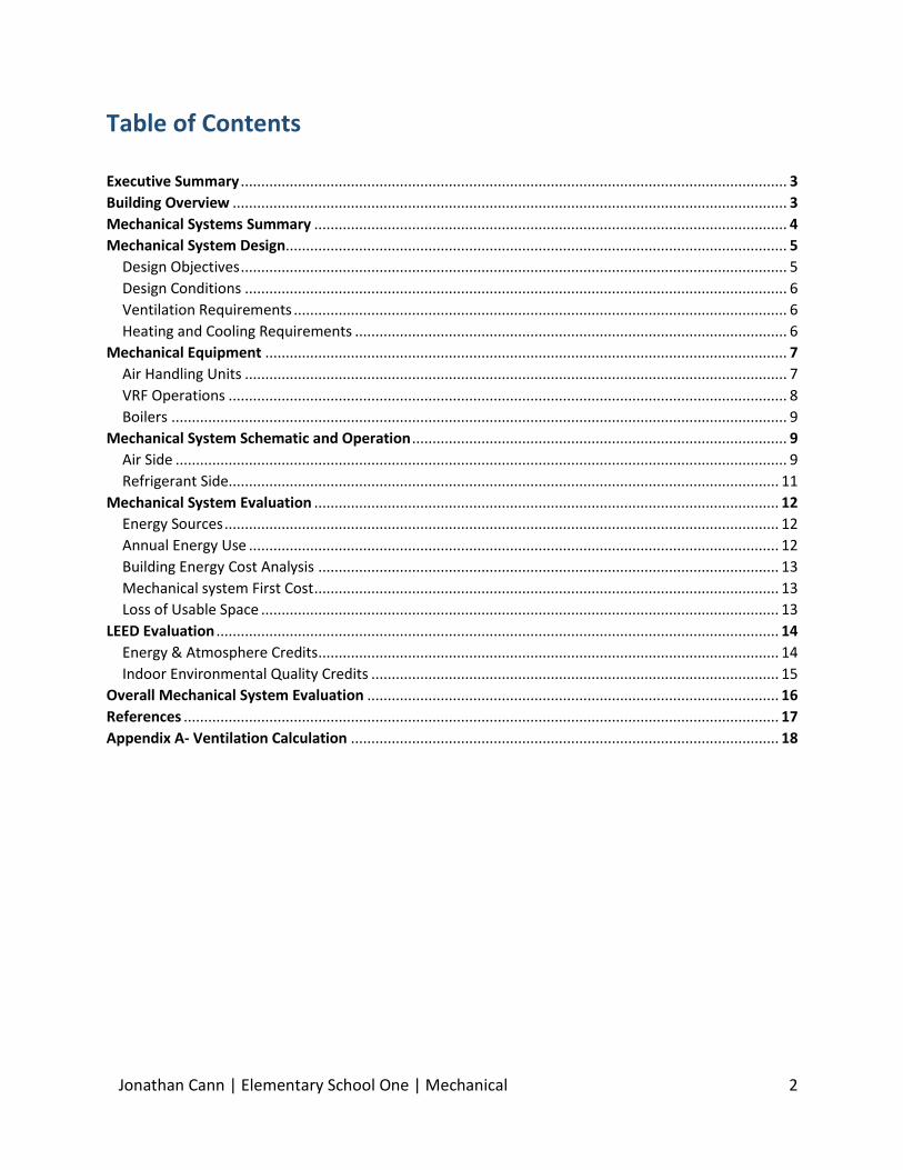
Building Overview Building Name: Elementary School One Location and Site: Town, Maryland Dates of Construction: 2010 – August 2011 Size: 84,400 sq. ft. Number of Stories: 3 above and 1 below grade
Figure 1: First Floor Plan. The red line separates the existing building and the addition. The existing is on the right and the addition is on the left.
Jonathan Cann | Elementary School One | Mechanical 4
Mechanical Systems Summary
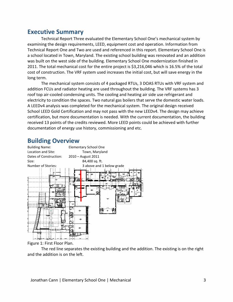
Elementary School One modernization involved a renovation of the existing building and adding an addition on the west side. All new mechanical systems were applied to both the existing and the addition. The mechanical system has three dedicated outside air RTUs that supply VAV boxes in each space. Each space then exhausts air back to the RTUs for heat wheel. There are three air-cooled VRF systems that condition these spaces with dedicated outside area.
Two RTUs serve the cafeteria and two serve the multipurpose room. There are also base board radiators and cabinet heaters in some of the spaces near the exterior. In the administrative section of the existing building, an AHU conditions the spaces with its own outside air intake. There are small AHUs that serve the computer room and telecom room, but they were not included in my analysis because of the insignificant impact.
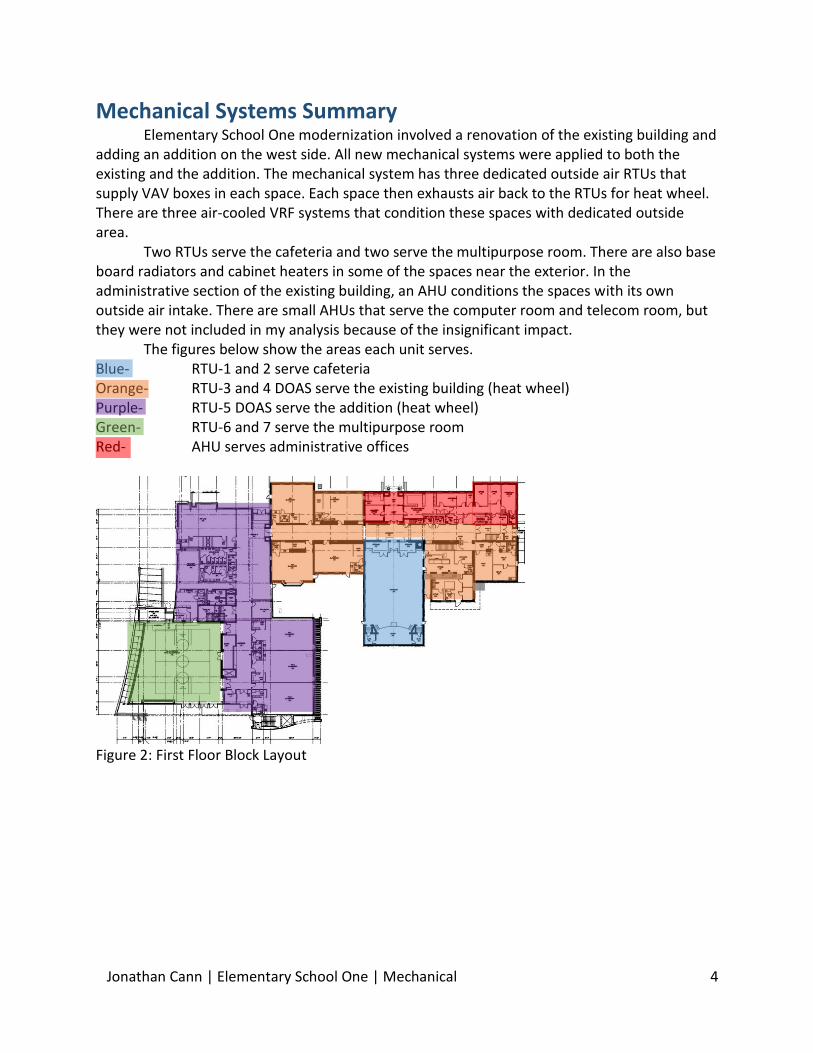
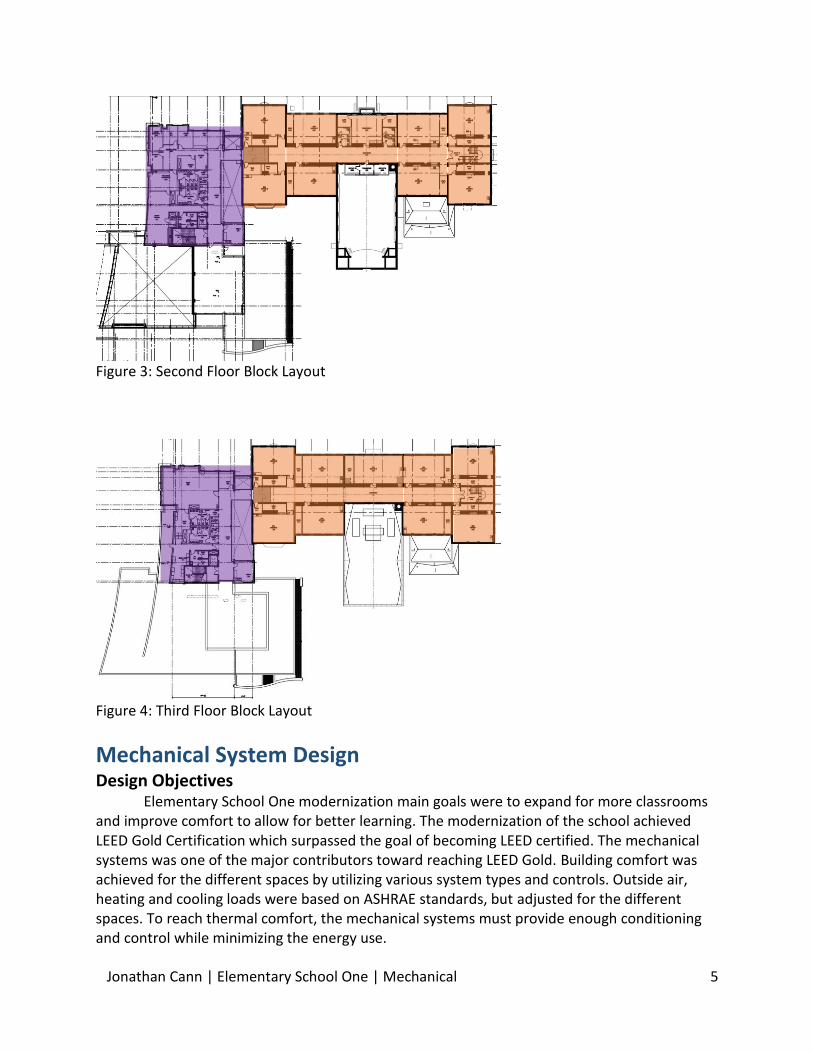
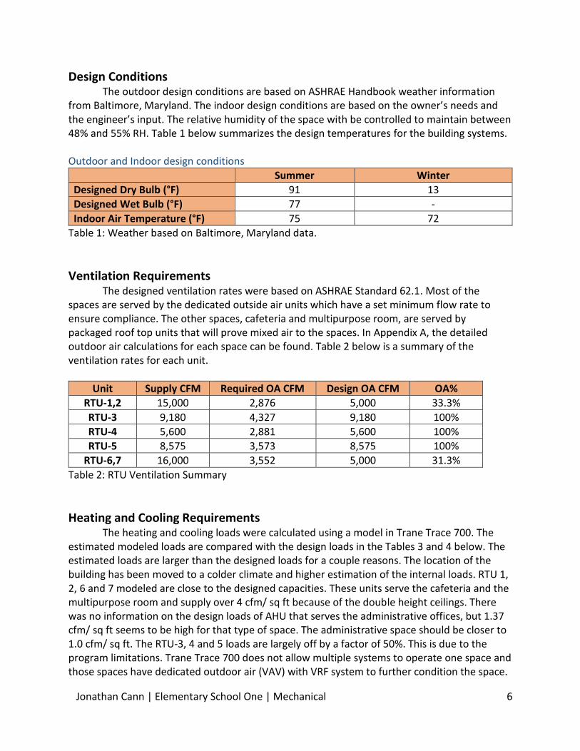
The figures below show the areas each unit serves. Blue- RTU-1 and 2 serve cafeteria Orange- RTU-3 and 4 DOAS serve the existing building (heat wheel) Purple- RTU-5 DOAS serve the addition (heat wheel) Green- RTU-6 and 7 serve the multipurpose room Red- AHU serves administrative offices
Figure 2: First Floor Block Layout
Jonathan Cann | Elementary School One | Mechanical 5
Figure 3: Second Floor Block Layout
Figure 4: Third Floor Block Layout
Mechanical System Design Design Objectives
Elementary School One modernization main goals were to expand for more classrooms and improve comfort to allow for better learning. The modernization of the school achieved LEED Gold Certification which surpassed the goal of becoming LEED certified. The mechanical systems was one of the major contributors toward reaching LEED Gold. Building comfort was achieved for the different spaces by utilizing various system types and controls. Outside air, heating and cooling loads were based on ASHRAE standards, but adjusted for the different spaces. To reach thermal comfort, the mechanical systems must provide enough conditioning and control while minimizing the energy use.
Jonathan Cann | Elementary School One | Mechanical 6
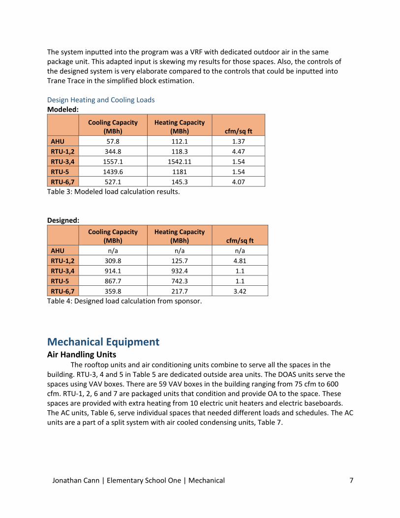
Design Conditions The outdoor design conditions are based on ASHRAE Handbook weather information
from Baltimore, Maryland. The indoor design conditions are based on the owner’s needs and the engineer’s input. The relative humidity of the space with be controlled to maintain between 48% and 55% RH. Table 1 below summarizes the design temperatures for the building systems. Outdoor and Indoor design conditions
Summer Winter
Designed Dry Bulb (°F) 91 13
Designed Wet Bulb (°F) 77 -
Indoor Air Temperature (°F) 75 72
Table 1: Weather based on Baltimore, Maryland data.
Ventilation Requirements The designed ventilation rates were based on ASHRAE Standard 62.1. Most of the
spaces are served by the dedicated outside air units which have a set minimum flow rate to ensure compliance. The other spaces, cafeteria and multipurpose room, are served by packaged roof top units that will prove mixed air to the spaces. In Appendix A, the detailed outdoor air calculations for each space can be found. Table 2 below is a summary of the ventilation rates for each unit.
Unit Supply CFM Required OA CFM Design OA CFM OA%
RTU-1,2 15,000 2,876 5,000 33.3%
RTU-3 9,180 4,327 9,180 100%
RTU-4 5,600 2,881 5,600 100%
RTU-5 8,575 3,573 8,575 100%
RTU-6,7 16,000 3,552 5,000 31.3%
Table 2: RTU Ventilation Summary
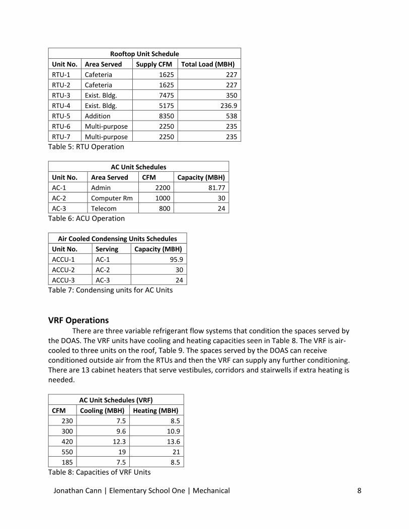
Heating and Cooling Requirements The heating and cooling loads were calculated using a model in Trane Trace 700. The
estimated modeled loads are compared with the design loads in the Tables 3 and 4 below. The estimated loads are larger than the designed loads for a couple reasons. The location of the building has been moved to a colder climate and higher estimation of the internal loads. RTU 1, 2, 6 and 7 modeled are close to the designed capacities. These units serve the cafeteria and the multipurpose room and supply over 4 cfm/ sq ft because of the double height ceilings. There was no information on the design loads of AHU that serves the administrative offices, but 1.37 cfm/ sq ft seems to be high for that type of space. The administrative space should be closer to 1.0 cfm/ sq ft. The RTU-3, 4 and 5 loads are largely off by a factor of 50%. This is due to the program limitations. Trane Trace 700 does not allow multiple systems to operate one space and those spaces have dedicated outdoor air (VAV) with VRF system to further condition the space.
Jonathan Cann | Elementary School One | Mechanical 7
The system inputted into the program was a VRF with dedicated outdoor air in the same package unit. This adapted input is skewing my results for those spaces. Also, the controls of the designed system is very elaborate compared to the controls that could be inputted into Trane Trace in the simplified block estimation. Design Heating and Cooling Loads Modeled:
Cooling Capacity
(MBh) Heating Capacity
(MBh) cfm/sq ft
AHU 57.8 112.1 1.37
RTU-1,2 344.8 118.3 4.47
RTU-3,4 1557.1 1542.11 1.54
RTU-5 1439.6 1181 1.54
RTU-6,7 527.1 145.3 4.07
Table 3: Modeled load calculation results. Designed:
Cooling Capacity
(MBh) Heating Capacity
(MBh) cfm/sq ft
AHU n/a n/a n/a
RTU-1,2 309.8 125.7 4.81
RTU-3,4 914.1 932.4 1.1
RTU-5 867.7 742.3 1.1
RTU-6,7 359.8 217.7 3.42
Table 4: Designed load calculation from sponsor.
Mechanical Equipment Air Handling Units
The rooftop units and air conditioning units combine to serve all the spaces in the building. RTU-3, 4 and 5 in Table 5 are dedicated outside area units. The DOAS units serve the spaces using VAV boxes. There are 59 VAV boxes in the building ranging from 75 cfm to 600 cfm. RTU-1, 2, 6 and 7 are packaged units that condition and provide OA to the space. These spaces are provided with extra heating from 10 electric unit heaters and electric baseboards. The AC units, Table 6, serve individual spaces that needed different loads and schedules. The AC units are a part of a split system with air cooled condensing units, Table 7.
Jonathan Cann | Elementary School One | Mechanical 8
Rooftop Unit Schedule
Unit No. Area Served Supply CFM Total Load (MBH)
RTU-1 Cafeteria 1625 227
RTU-2 Cafeteria 1625 227
RTU-3 Exist. Bldg. 7475 350
RTU-4 Exist. Bldg. 5175 236.9
RTU-5 Addition 8350 538
RTU-6 Multi-purpose 2250 235
RTU-7 Multi-purpose 2250 235
Table 5: RTU Operation
AC Unit Schedules
Unit No. Area Served CFM Capacity (MBH)
AC-1 Admin 2200 81.77
AC-2 Computer Rm 1000 30
AC-3 Telecom 800 24
Table 6: ACU Operation
Air Cooled Condensing Units Schedules
Unit No. Serving Capacity (MBH)
ACCU-1 AC-1 95.9
ACCU-2 AC-2 30
ACCU-3 AC-3 24
Table 7: Condensing units for AC Units
VRF Operations There are three variable refrigerant flow systems that condition the spaces served by
the DOAS. The VRF units have cooling and heating capacities seen in Table 8. The VRF is air-cooled to three units on the roof, Table 9. The spaces served by the DOAS can receive conditioned outside air from the RTUs and then the VRF can supply any further conditioning. There are 13 cabinet heaters that serve vestibules, corridors and stairwells if extra heating is needed.
AC Unit Schedules (VRF)
CFM Cooling (MBH) Heating (MBH)
230 7.5 8.5
300 9.6 10.9
420 12.3 13.6
550 19 21
185 7.5 8.5
Table 8: Capacities of VRF Units
Jonathan Cann | Elementary School One | Mechanical 9
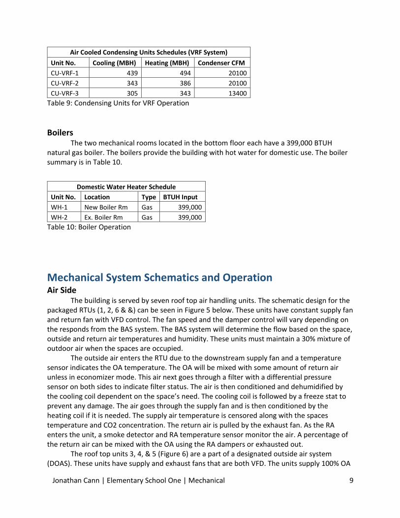
Air Cooled Condensing Units Schedules (VRF System)
Unit No. Cooling (MBH) Heating (MBH) Condenser CFM
CU-VRF-1 439 494 20100
CU-VRF-2 343 386 20100
CU-VRF-3 305 343 13400
Table 9: Condensing Units for VRF Operation
Boilers The two mechanical rooms located in the bottom floor each have a 399,000 BTUH
natural gas boiler. The boilers provide the building with hot water for domestic use. The boiler summary is in Table 10.
Domestic Water Heater Schedule
Unit No. Location Type BTUH Input
WH-1 New Boiler Rm Gas 399,000
WH-2 Ex. Boiler Rm Gas 399,000
Table 10: Boiler Operation
Mechanical System Schematics and Operation
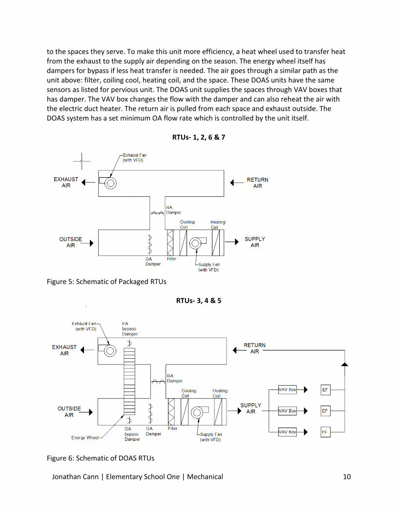
Air Side The building is served by seven roof top air handling units. The schematic design for the
packaged RTUs (1, 2, 6 & &) can be seen in Figure 5 below. These units have constant supply fan and return fan with VFD control. The fan speed and the damper control will vary depending on the responds from the BAS system. The BAS system will determine the flow based on the space, outside and return air temperatures and humidity. These units must maintain a 30% mixture of outdoor air when the spaces are occupied.
The outside air enters the RTU due to the downstream supply fan and a temperature sensor indicates the OA temperature. The OA will be mixed with some amount of return air unless in economizer mode. This air next goes through a filter with a differential pressure sensor on both sides to indicate filter status. The air is then conditioned and dehumidified by the cooling coil dependent on the space’s need. The cooling coil is followed by a freeze stat to prevent any damage. The air goes through the supply fan and is then conditioned by the heating coil if it is needed. The supply air temperature is censored along with the spaces temperature and CO2 concentration. The return air is pulled by the exhaust fan. As the RA enters the unit, a smoke detector and RA temperature sensor monitor the air. A percentage of the return air can be mixed with the OA using the RA dampers or exhausted out.
The roof top units 3, 4, & 5 (Figure 6) are a part of a designated outside air system (DOAS). These units have supply and exhaust fans that are both VFD. The units supply 100% OA
Jonathan Cann | Elementary School One | Mechanical 10
to the spaces they serve. To make this unit more efficiency, a heat wheel used to transfer heat from the exhaust to the supply air depending on the season. The energy wheel itself has dampers for bypass if less heat transfer is needed. The air goes through a similar path as the unit above: filter, coiling cool, heating coil, and the space. These DOAS units have the same sensors as listed for pervious unit. The DOAS unit supplies the spaces through VAV boxes that has damper. The VAV box changes the flow with the damper and can also reheat the air with the electric duct heater. The return air is pulled from each space and exhaust outside. The DOAS system has a set minimum OA flow rate which is controlled by the unit itself.
RTUs- 1, 2, 6 & 7
Figure 5: Schematic of Packaged RTUs
RTUs- 3, 4 & 5
Figure 6: Schematic of DOAS RTUs
Jonathan Cann | Elementary School One | Mechanical 11
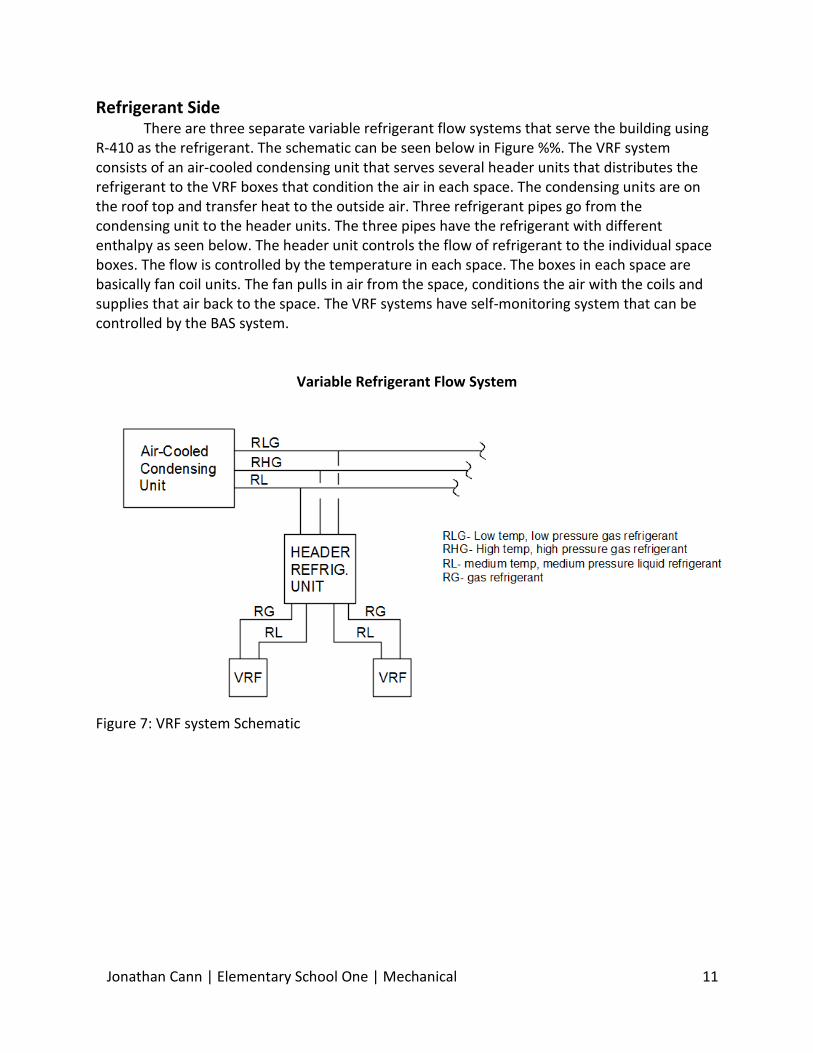
Refrigerant Side There are three separate variable refrigerant flow systems that serve the building using
R-410 as the refrigerant. The schematic can be seen below in Figure %%. The VRF system consists of an air-cooled condensing unit that serves several header units that distributes the refrigerant to the VRF boxes that condition the air in each space. The condensing units are on the roof top and transfer heat to the outside air. Three refrigerant pipes go from the condensing unit to the header units. The three pipes have the refrigerant with different enthalpy as seen below. The header unit controls the flow of refrigerant to the individual space boxes. The flow is controlled by the temperature in each space. The boxes in each space are basically fan coil units. The fan pulls in air from the space, conditions the air with the coils and supplies that air back to the space. The VRF systems have self-monitoring system that can be controlled by the BAS system.
Variable Refrigerant Flow System
Figure 7: VRF system Schematic
Jonathan Cann | Elementary School One | Mechanical 12
Mechanical System Evaluation Energy Sources
Elementary School One’s energy sources are electricity and natural gas. Electricity provides power to most of the building and the natural gas provides power to the two water heaters. Both of these energy sources come from the city provider. Table 11 summarizes the utility rates.
Energy Source Average Rate
Electricity $0.131/kWH
Natural Gas $1.044/therm
Table 11: Average Utility Rates
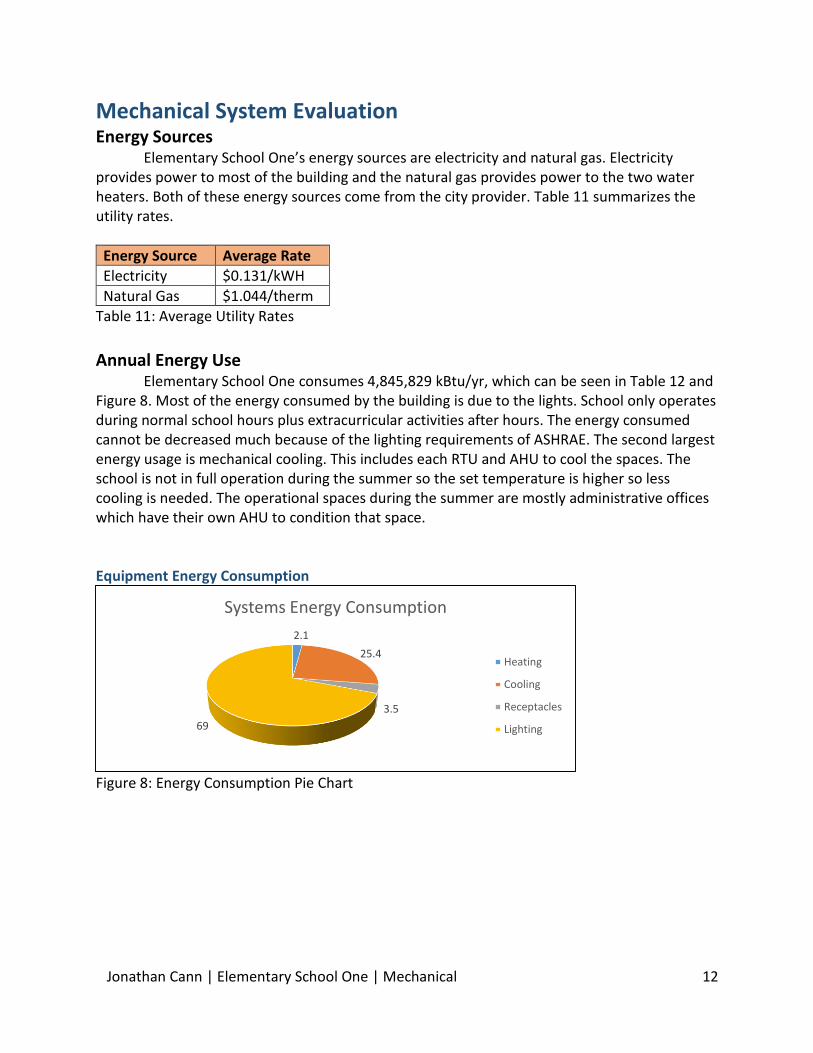
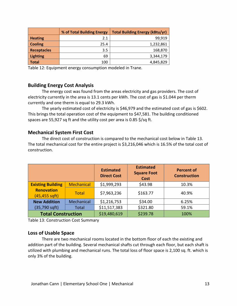
Annual Energy Use Elementary School One consumes 4,845,829 kBtu/yr, which can be seen in Table 12 and Figure 8. Most of the energy consumed by the building is due to the lights. School only operates during normal school hours plus extracurricular activities after hours. The energy consumed cannot be decreased much because of the lighting requirements of ASHRAE. The second largest energy usage is mechanical cooling. This includes each RTU and AHU to cool the spaces. The school is not in full operation during the summer so the set temperature is higher so less cooling is needed. The operational spaces during the summer are mostly administrative offices which have their own AHU to condition that space. Equipment Energy Consumption
Figure 8: Energy Consumption Pie Chart
2.1
25.4
3.5
69
Systems Energy Consumption
Heating
Cooling
Receptacles
Lighting
Jonathan Cann | Elementary School One | Mechanical 13
% of Total Building Energy Total Building Energy (kBtu/yr)
Heating 2.1 99,919
Cooling 25.4 1,232,861
Receptacles 3.5 168,870
Lighting 69 3,344,179
Total 100 4,845,829
Table 12: Equipment energy consumption modeled in Trane.
Building Energy Cost Analysis The energy cost was found from the areas electricity and gas providers. The cost of electricity currently in the area is 13.1 cents per kWh. The cost of gas is $1.044 per therm currently and one therm is equal to 29.3 kWh. The yearly estimated cost of electricity is $46,979 and the estimated cost of gas is $602. This brings the total operation cost of the equipment to $47,581. The building conditioned spaces are 55,927 sq ft and the utility cost per area is 0.85 $/sq ft.
Mechanical System First Cost
The direct cost of construction is compared to the mechanical cost below in Table 13. The total mechanical cost for the entire project is $3,216,046 which is 16.5% of the total cost of construction.
Estimated Direct Cost
Estimated Square Foot
Cost
Percent of Construction
Existing Building Renovation (45,455 sqft)
Mechanical $1,999,293 $43.98 10.3%
Total $7,963,236 $163.77 40.9%
New Addition (35,790 sqft)
Mechanical $1,216,753 $34.00 6.25%
Total $11,517,383 $321.80 59.1%
Total Construction $19,480,619 $239.78 100%
Table 13: Construction Cost Summary
Loss of Usable Space
There are two mechanical rooms located in the bottom floor of each the existing and addition part of the building. Several mechanical shafts cut through each floor, but each shaft is utilized with plumbing and mechanical runs. The total loss of floor space is 2,100 sq. ft. which is only 3% of the building.
Jonathan Cann | Elementary School One | Mechanical 14
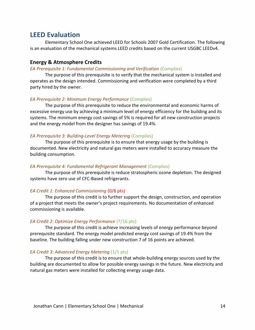
LEED Evaluation Elementary School One achieved LEED for Schools 2007 Gold Certification. The following
is an evaluation of the mechanical systems LEED credits based on the current USGBC LEEDv4.
Energy & Atmosphere Credits EA Prerequisite 1: Fundamental Commissioning and Verification (Complies) The purpose of this prerequisite is to verify that the mechanical system is installed and operates as the design intended. Commissioning and verification were completed by a third party hired by the owner. EA Prerequisite 2: Minimum Energy Performance (Complies) The purpose of this prerequisite to reduce the environmental and economic harms of excessive energy use by achieving a minimum level of energy efficiency for the building and its systems. The minimum energy cost savings of 5% is required for all new construction projects and the energy model from the designer has savings of 19.4%. EA Prerequisite 3: Building-Level Energy Metering (Complies) The purpose of this prerequisite is to ensure that energy usage by the building is documented. New electricity and natural gas meters were installed to accuracy measure the building consumption. EA Prerequisite 4: Fundamental Refrigerant Management (Complies) The purpose of this prerequisite is reduce stratospheric ozone depletion. The designed systems have zero use of CFC-Based refrigerants. EA Credit 1: Enhanced Commissioning (0/6 pts) The purpose of this credit is to further support the design, construction, and operation of a project that meets the owner’s project requirements. No documentation of enhanced commissioning is available. EA Credit 2: Optimize Energy Performance (7/16 pts) The purpose of this credit is achieve increasing levels of energy performance beyond prerequisite standard. The energy model predicted energy cost savings of 19.4% from the baseline. The building falling under new construction 7 of 16 points are achieved. EA Credit 3: Advanced Energy Metering (1/1 pts) The purpose of this credit is to ensure that whole-building energy sources used by the building are documented to allow for possible energy savings in the future. New electricity and natural gas meters were installed for collecting energy usage data.
Jonathan Cann | Elementary School One | Mechanical 15
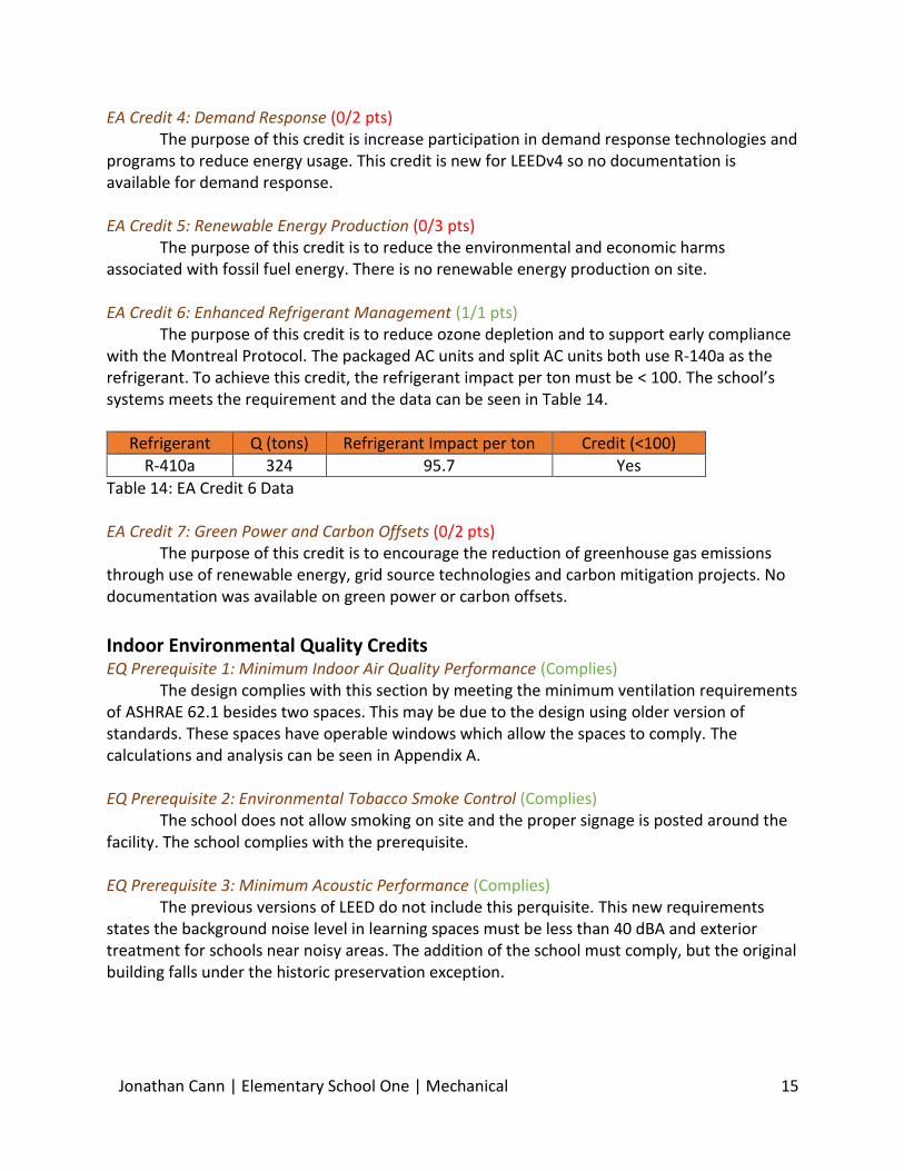
EA Credit 4: Demand Response (0/2 pts) The purpose of this credit is increase participation in demand response technologies and programs to reduce energy usage. This credit is new for LEEDv4 so no documentation is available for demand response. EA Credit 5: Renewable Energy Production (0/3 pts) The purpose of this credit is to reduce the environmental and economic harms associated with fossil fuel energy. There is no renewable energy production on site. EA Credit 6: Enhanced Refrigerant Management (1/1 pts) The purpose of this credit is to reduce ozone depletion and to support early compliance with the Montreal Protocol. The packaged AC units and split AC units both use R-140a as the refrigerant. To achieve this credit, the refrigerant impact per ton must be < 100. The school’s systems meets the requirement and the data can be seen in Table 14.
Refrigerant Q (tons) Refrigerant Impact per ton Credit (<100)
R-410a 324 95.7 Yes
Table 14: EA Credit 6 Data EA Credit 7: Green Power and Carbon Offsets (0/2 pts) The purpose of this credit is to encourage the reduction of greenhouse gas emissions through use of renewable energy, grid source technologies and carbon mitigation projects. No documentation was available on green power or carbon offsets.
Indoor Environmental Quality Credits EQ Prerequisite 1: Minimum Indoor Air Quality Performance (Complies) The design complies with this section by meeting the minimum ventilation requirements of ASHRAE 62.1 besides two spaces. This may be due to the design using older version of standards. These spaces have operable windows which allow the spaces to comply. The calculations and analysis can be seen in Appendix A. EQ Prerequisite 2: Environmental Tobacco Smoke Control (Complies) The school does not allow smoking on site and the proper signage is posted around the facility. The school complies with the prerequisite. EQ Prerequisite 3: Minimum Acoustic Performance (Complies) The previous versions of LEED do not include this perquisite. This new requirements states the background noise level in learning spaces must be less than 40 dBA and exterior treatment for schools near noisy areas. The addition of the school must comply, but the original building falls under the historic preservation exception.

Jonathan Cann | Elementary School One | Mechanical 16
EQ Credit 1: Enhanced Indoor Air Quality Strategies (1/2 pts) The purpose of this credit is improve indoor air quality for the occupants. The design does have CO2 sensors in each occupied space, but does not design 30% OA increase of the requirement to achieve the 2 points in this section. EQ Credit 4: Indoor Air Quality Assessment (0/2 pts) The purpose of this credit to establish better quality indoor air in the building after construction and during occupancy. No documentation was found on air testing or air flush outs. This credit was not in the previous versions of LEED. EQ Credit 5: Thermal Comfort (1/1 pts) The school complies with ASHRAE 55-2010. The set points for temperature, humidity and ventilation follow that standard. The thermal comfort satisfies 80% of the occupants by having thermostats and occupancy sensors in each space controlling the individual space fan coil unit. EQ Credit 9: Acoustical Performance (2/2 pts) The purpose of this credit is to provide learning spaces that promotes occupants’ well-being, productivity, and communications through acoustic design. An acoustical consultant was hired and verified that the spaces do meet School LEED Ratings. The problem spaces do not affect LEED rating because they are not learning spaces.
Overall Mechanical System Evaluation Elementary School One modernization main goals were to expand for more classrooms and improve comfort to allow for better learning while being energy efficient. One of the main difficulties in the design is to balance energy efficient and initial cost of construction. The building’s mechanical system provides comfortable learning spaces while meeting requirements of ventilation and conditioning. The DOAS roof top units combined with the VRF system provides thermal and acoustical comfort to the learning spaces. The combination of systems make for very energy efficient mechanical system. The packaged roof top units that serve the cafeteria and multipurpose room fit the needs for the space. The conditioning of these spaces might be able to be served in a more energy efficient way. The cost of the modernization to Elementary School One was $19,480,619 with the mechanical system cost at $3,216,046. The sustainability of the systems should be worth the initial cost of the system. Through further research and evolution, the building’s mechanical systems could save more energy by implanting new equipment and renewable energy sources. The original design of the mechanical system meets the design objectives of the owner and requirements of the standards. More evaluations and research may provide ways to other options and technologies that may work for Elementary School One.
Jonathan Cann | Elementary School One | Mechanical 17
References
ASHRAE (2013) Standard 62.1- Ventilation for Acceptable Indoor Air Quality
ASHRAE (2013) Standard 90.1- Energy Standard For building Except Low-Rise Residential Buildings
"Department of Public Works." Department of Public Works. N.p., n.d. Web. 06 Oct. 2014.
"U.S. Bureau of Labor Statistics." U.S. Bureau of Labor Statistics. U.S. Bureau of Labor Statistics, n.d.
Web. 05 Oct. 2014.
Jonathan Cann | Elementary School One | Mechanical 18
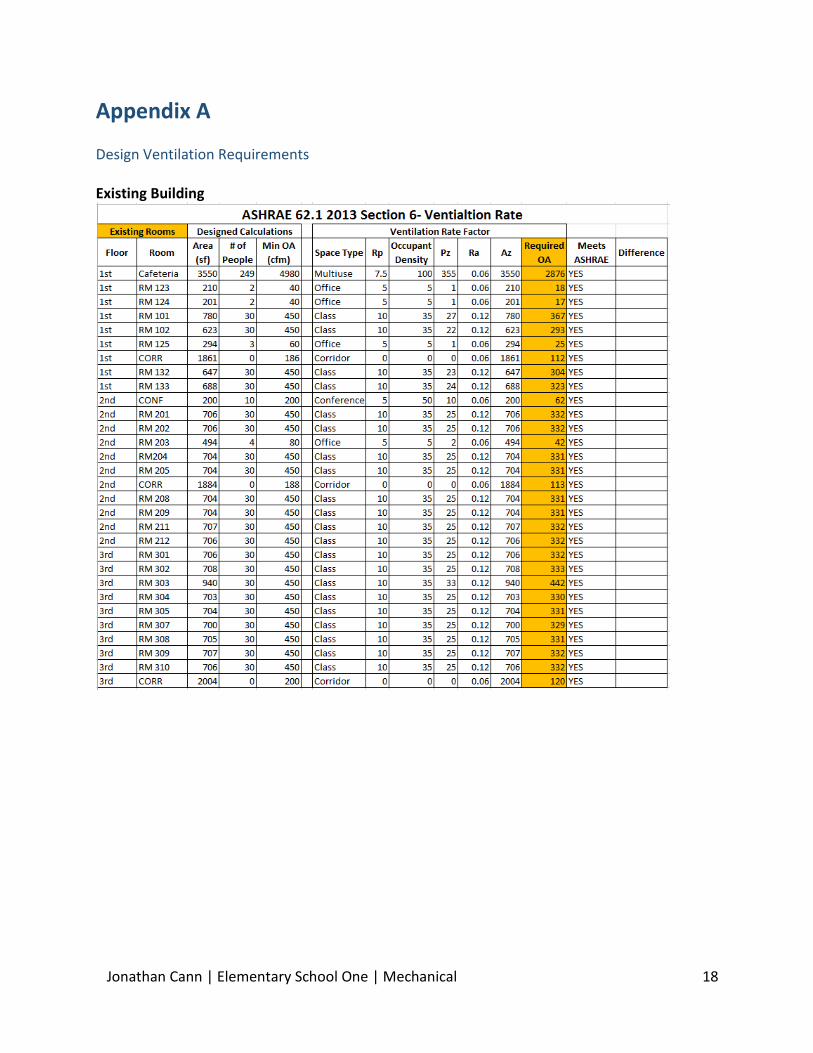
Appendix A
Design Ventilation Requirements Existing Building

Jonathan Cann | Elementary School One | Mechanical 19
Building Addition