TECHNICAL rEPORT oNE: ashrae STANDARDS 62.1 AND 90.1 ... · TECHNICAL REPORT ONE: ASHRAE STANDARDS...
21
Samuel T Bridwell DR. JAMES FREIJHAUT NEOMED Research and Graduate Education Building TECHNICAL REPORT ONE: ASHRAE STANDARDS 62.1 AND 90.1 EVALUATION September 18, 2014
Transcript of TECHNICAL rEPORT oNE: ashrae STANDARDS 62.1 AND 90.1 ... · TECHNICAL REPORT ONE: ASHRAE STANDARDS...

Samuel T Bridwell
DR. JAMES FREIJHAUT NEOMED Research and Graduate Education Building
TECHNICAL REPORT ONE: ASHRAE STANDARDS 62.1 AND
90.1 EVALUATION
September 18, 2014
1 Sam Bridwell │ Mechanical │ Dr. James Freihaut │ NEOMED RGE and CMU Expansion
TECHNICAL REPORT ONE: ASHRAE STANDARDS 62.1 AND 90.1 EVALUATION
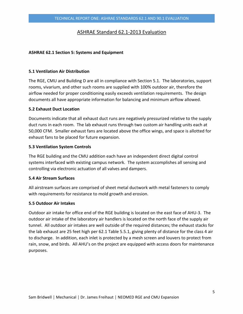
Table of Contents
Executive Summary 2
Building Overview 3
Mechanical Systems Overview 4
ASHRAE Standard 62.1.5-2013 Evaluation 5
ASHRAE Standard 62.1.6-2013 Evaluation 9
ASHRAE Standard 90.1-2013 Evaluation 11
References 13
Appendix 14

2 Sam Bridwell │ Mechanical │ Dr. James Freihaut │ NEOMED RGE and CMU Expansion
TECHNICAL REPORT ONE: ASHRAE STANDARDS 62.1 AND 90.1 EVALUATION
Executive Summary
This Report is an evaluation of the NEOMED Research and Graduate Education and Comparable
Medical Unit with respect to ASHRAE Standards 62.1 and 90.1. The Project is located on the
Northeast Ohio Medical University campus, at 4209 Ohio 44, Rootstown, Ohio. The facility is
used for graduate-level research and education in the medical field, with laboratories,
operating rooms, a vivarium, and numerous biological support spaces. The project was
completed in August 2013.
Through investigation of the standards, The RGE and CMU addition are generally up to code.
However, there are a number of opportunities to improve efficiency concerning ventilation
rates for non-research areas and energy recovery from exhaust.

3 Sam Bridwell │ Mechanical │ Dr. James Freihaut │ NEOMED RGE and CMU Expansion
TECHNICAL REPORT ONE: ASHRAE STANDARDS 62.1 AND 90.1 EVALUATION
Building Overview
The project is comprised of three additions to the NEOMED campus. The main addition is the Research and Graduate Education Center, a four-story 63,000 square foot biomedical research building. The first three floors are fully built out with laboratories, support rooms, and offices, while the top floor is shelled in and will be built out as the research program grows. There is a 6,000 square foot basement to house stand-alone utilities.
The second component is a 14,500 square foot addition to the Comparable Medical Unit, which provides animal care services. Lastly, several existing laboratories in Building D were renovated.

4 Sam Bridwell │ Mechanical │ Dr. James Freihaut │ NEOMED RGE and CMU Expansion
TECHNICAL REPORT ONE: ASHRAE STANDARDS 62.1 AND 90.1 EVALUATION
Mechanical Systems Overview
Campus Utilities will not be utilized for this project; there is a stand-alone system of chillers,
medium pressure steam generators, and hot water boilers located in the basement area of the
addition. The RGE Building has two 100% outside air handling units each sized at 50,000 CFM
respectively and a smaller 28,000 CFM office unit with return air. The CMU has its own 35,000
CFM 100% outdoor air unit as well.
5 Sam Bridwell │ Mechanical │ Dr. James Freihaut │ NEOMED RGE and CMU Expansion
TECHNICAL REPORT ONE: ASHRAE STANDARDS 62.1 AND 90.1 EVALUATION
ASHRAE Standard 62.1-2013 Evaluation
ASHRAE 62.1 Section 5: Systems and Equipment
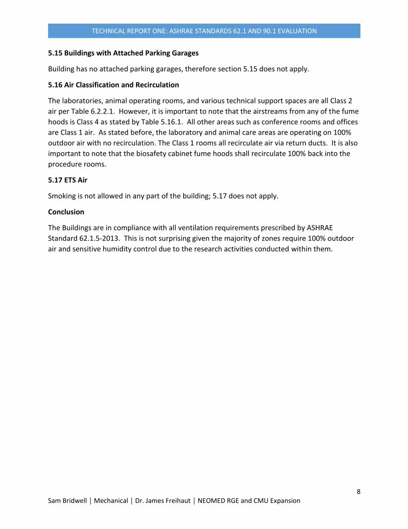
5.1 Ventilation Air Distribution
The RGE, CMU and Building D are all in compliance with Section 5.1. The laboratories, support
rooms, vivarium, and other such rooms are supplied with 100% outdoor air, therefore the
airflow needed for proper conditioning easily exceeds ventilation requirements. The design
documents all have appropriate information for balancing and minimum airflow allowed.
5.2 Exhaust Duct Location
Documents indicate that all exhaust duct runs are negatively pressurized relative to the supply
duct runs in each room. The lab exhaust runs through two custom air handling units each at
50,000 CFM. Smaller exhaust fans are located above the office wings, and space is allotted for
exhaust fans to be placed for future expansion.
5.3 Ventilation System Controls
The RGE building and the CMU addition each have an independent direct digital control
systems interfaced with existing campus network. The system accomplishes all sensing and
controlling via electronic actuation of all valves and dampers.
5.4 Air Stream Surfaces
All airstream surfaces are comprised of sheet metal ductwork with metal fasteners to comply
with requirements for resistance to mold growth and erosion.
5.5 Outdoor Air Intakes
Outdoor air intake for office end of the RGE building is located on the east face of AHU-3. The
outdoor air intake of the laboratory air handlers is located on the north face of the supply air
tunnel. All outdoor air intakes are well outside of the required distances; the exhaust stacks for
the lab exhaust are 25 feet high per 62.1 Table 5.5.1, giving plenty of distance for the class 4 air
to discharge. In addition, each inlet is protected by a mesh screen and louvers to protect from
rain, snow, and birds. All AHU’s on the project are equipped with access doors for maintenance
purposes.

6 Sam Bridwell │ Mechanical │ Dr. James Freihaut │ NEOMED RGE and CMU Expansion
TECHNICAL REPORT ONE: ASHRAE STANDARDS 62.1 AND 90.1 EVALUATION
Figure 1 (Source: ASHRAE 62.1-2013)
5.6 Local Capture of Contaminants
All areas with equipment that generate contaminates, such as labs and restrooms, have
exhaust to capture contaminates and direct outdoors away from any intake openings.
5.7 Combustion Air
All laboratory spaces are equipped with fume hoods for removal of any potential combustion
products.
5.8 Particulate Matter Removal
Supply air tunnels have a MERV-9 pre-filter and a MERV-14 after-filter within each air handler.
Heat recovery coils within exhaust tunnels have MERV-9 pre-filters. Also, room-side
replaceable “filter grilles” are used for exhaust of the animal holding room in the CMU. All of
these meet the minimum ASHRAE standard of MERV-8 filtration.
5.9 Dehumidification Systems
Lab and support spaces are designed at 35% humidity in winter and 50% humidity in summer.
The vivarium is designed at 30-40% winter humidity and 50% summer humidity. These are all

7 Sam Bridwell │ Mechanical │ Dr. James Freihaut │ NEOMED RGE and CMU Expansion
TECHNICAL REPORT ONE: ASHRAE STANDARDS 62.1 AND 90.1 EVALUATION
less than the required 65% maximum. Regarding section 5.9.2, the RGE has two custom air
handling units, with both supply and exhaust at 37,500 CFM for 100% outdoor air intake. The
CMU addition has an 85,000 CFM supply and exhaust in a similar fashion.
5.10 Drain Pans
No mention of drain pans is given in the specifications
5.11 Finned-Tube Coils and Heat Exchangers
Plate and frame heat exchangers are utilized on this project rather than finned-tube heat
exchangers
5.12 Humidifiers and Water-Spray Systems
The project utilizes Nortec NH series electrode steam humidifiers which are specified to use
potable water and drain pans per ASHRAE standard.
5.13 Access for Inspection, Cleaning, and Maintenance
Sufficient access to HVAC equipment has been designed.
5.14 Building Envelope and Interior Surfaces
Architectural wall sections such as Figure 2 indicate a building envelope with rigid insulation,
moisture barriers, and batt insulation between studs.
Figure 2: architectural wall section
8 Sam Bridwell │ Mechanical │ Dr. James Freihaut │ NEOMED RGE and CMU Expansion
TECHNICAL REPORT ONE: ASHRAE STANDARDS 62.1 AND 90.1 EVALUATION
5.15 Buildings with Attached Parking Garages
Building has no attached parking garages, therefore section 5.15 does not apply.
5.16 Air Classification and Recirculation
The laboratories, animal operating rooms, and various technical support spaces are all Class 2
air per Table 6.2.2.1. However, it is important to note that the airstreams from any of the fume
hoods is Class 4 as stated by Table 5.16.1. All other areas such as conference rooms and offices
are Class 1 air. As stated before, the laboratory and animal care areas are operating on 100%
outdoor air with no recirculation. The Class 1 rooms all recirculate air via return ducts. It is also
important to note that the biosafety cabinet fume hoods shall recirculate 100% back into the
procedure rooms.
5.17 ETS Air
Smoking is not allowed in any part of the building; 5.17 does not apply.
Conclusion
The Buildings are in compliance with all ventilation requirements prescribed by ASHRAE
Standard 62.1.5-2013. This is not surprising given the majority of zones require 100% outdoor
air and sensitive humidity control due to the research activities conducted within them.
9 Sam Bridwell │ Mechanical │ Dr. James Freihaut │ NEOMED RGE and CMU Expansion
TECHNICAL REPORT ONE: ASHRAE STANDARDS 62.1 AND 90.1 EVALUATION
ASHRAE 62.1 Section 6: Procedures
6.1 General
The site’s outdoor air has no contamination issues and is deemed acceptable for ventilation
purposes. Proper ventilation rates are hereby calculated via the prescriptive Ventilation Rate
Procedure and the Exhaust Rate Procedure and compared to the existing design specifications.
No natural ventilation strategies are used in the design.
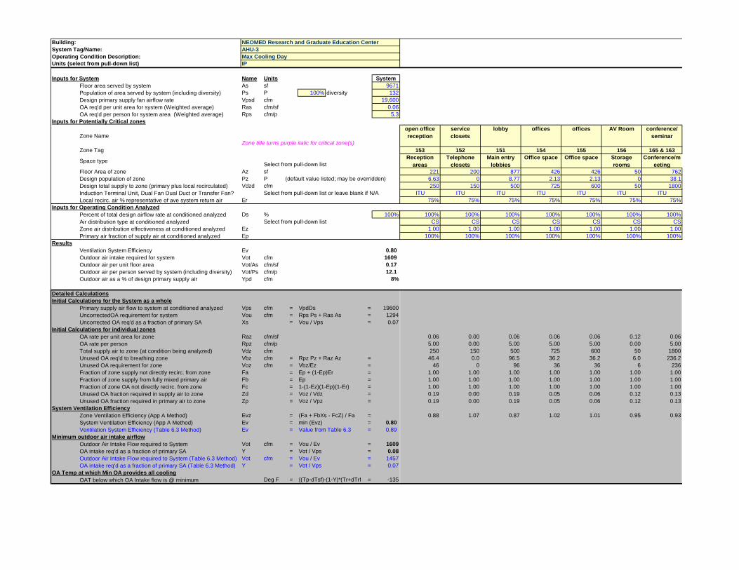
6.2 Ventilation Rate Procedure
A preconfigured excel spreadsheet was used to calculate ventilation needed for the offices and
conference rooms to the east end of the RGE building, covered by AHU-3. In this project, this
was the only air handler configuration that was not configured for 100% outdoor air intake.
The breakdown from the spreadsheet calculations is located in Appendix A.
First, breathing zone outdoor air flow rates are calculated with Equation 6-1 from ASHRA 62.1-
2013 for each room
Vbz = Rp*Pz + Ra*Az
Where Rp is outdoor airflow rate per person, Pz is zone population by occupancy class, Ra is
outdoor airflow rater per area, and Az is the area covered by the zone. Table 6-1 of ASHRAE
Standard 62.1-2013 contains values for both Rp and Ra, and is referenced by the spreadsheet.
The next step is to find and factor in the zone air distribution effectiveness Ez, found in Table 6-
2. In all instances examined, supply air was delivered via ceiling diffusers at cooling
temperature, so Ez was 1.0 all around. These values are also referenced in the spreadsheet in
Appendix A.
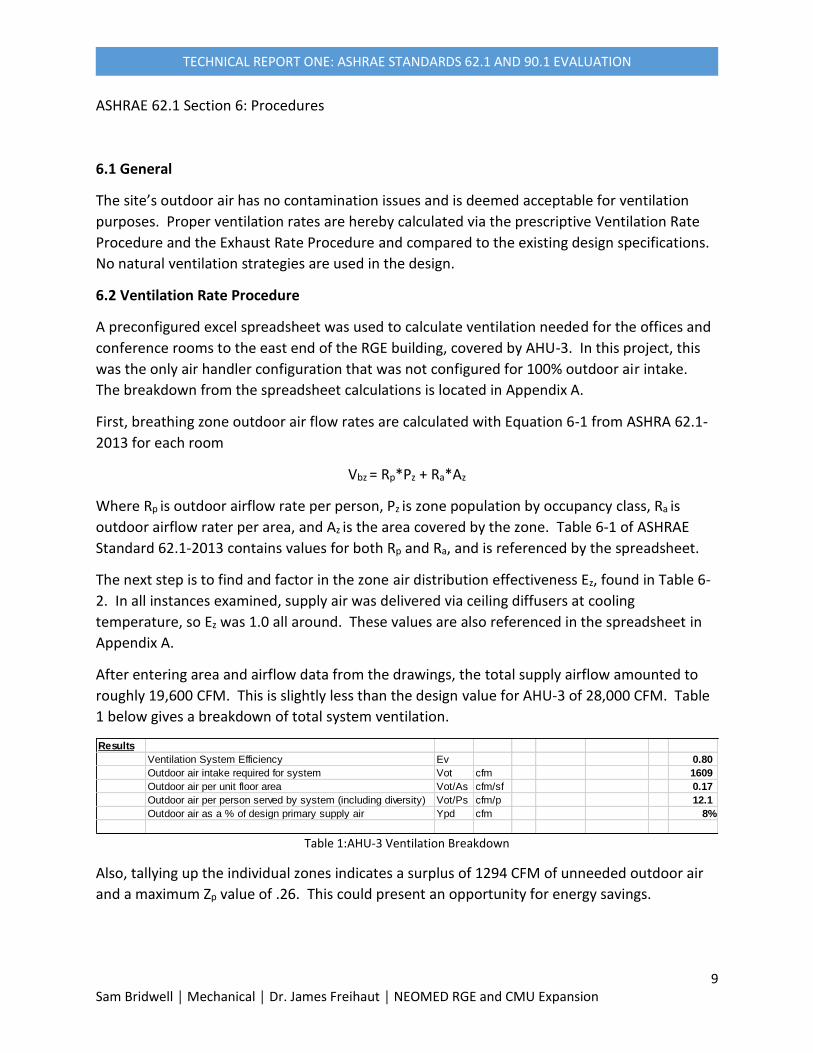
After entering area and airflow data from the drawings, the total supply airflow amounted to
roughly 19,600 CFM. This is slightly less than the design value for AHU-3 of 28,000 CFM. Table
1 below gives a breakdown of total system ventilation.
Table 1:AHU-3 Ventilation Breakdown
Also, tallying up the individual zones indicates a surplus of 1294 CFM of unneeded outdoor air
and a maximum Zp value of .26. This could present an opportunity for energy savings.
Results
Ventilation System Efficiency Ev 0.80
Outdoor air intake required for system Vot cfm 1609
Outdoor air per unit floor area Vot/As cfm/sf 0.17
Outdoor air per person served by system (including diversity) Vot/Ps cfm/p 12.1
Outdoor air as a % of design primary supply air Ypd cfm 8%
10 Sam Bridwell │ Mechanical │ Dr. James Freihaut │ NEOMED RGE and CMU Expansion
TECHNICAL REPORT ONE: ASHRAE STANDARDS 62.1 AND 90.1 EVALUATION
Conclusion
As a science and research facility, the RGE and CMU buildings by necessity have large turnover
in airflow. The analysis shows that even in the minority of non-research zones there are
moderate energy savings to be had. There are likely even greater savings to be had if one
examines the heat recovery methods used for the rest of the project.

11 Sam Bridwell │ Mechanical │ Dr. James Freihaut │ NEOMED RGE and CMU Expansion
TECHNICAL REPORT ONE: ASHRAE STANDARDS 62.1 AND 90.1 EVALUATION
ASHRAE Standard 90.1-2013 Evaluation
Section 5: Building Envelope
5.1 General
As shown by Figure B1-1 in ASHRAE Standard 90.1-2013 Section 5.1.4, the project’s location in
Rootstown, Ohio places it in the 5A Climate Zone, a relatively cool, moist region.
5.2 Compliance Paths
Here we will elect to use the prescriptive evaluation for the building envelope outline in Section
5.5 of the code.
5.4 Mandatory Provisions
The building is constructed with a continuous air and water membrane throughout the entirety
of the envelope. In addition, the entrances to the RGE and CMU have vestibules per section
5.4.3.4 of the code.
5.5 Prescriptive Building Envelope Option
Insulation values for the envelope are not available, making the envelope difficult to access.
More information finding will be required.
Section 6: Heating, Ventilation, and Air Conditioning

12 Sam Bridwell │ Mechanical │ Dr. James Freihaut │ NEOMED RGE and CMU Expansion
TECHNICAL REPORT ONE: ASHRAE STANDARDS 62.1 AND 90.1 EVALUATION
6.4 Mandatory Provisions
The prescriptive path outlined in Section 6.4 of Standard 90.1-2013 shall be followed as the
building project does not meet the size criteria for the simplified approach outlined in Section
6.3. All equipment meets efficiency standards outlined in the tables of Section 6.8 and load
calculations were conducted in the program Chvac 7 in accordance with ASHRAE Standards.
The DDC system mentioned in the Standard 62.1.5.3-2013 controls all equipment in accordance
with Standard 6.4.3.
6.5 Prescriptive Path
AHU-3 is outfitted with an economizer in accordance with code Section 6.5.1. The automatic
temperature control system governs the zone controls via digital sensors and actuators. Also,
given the data presented in the analysis of Standard 62.1.6.2 the amount of outdoor air utilized
by the office air handler is less than the amount needed to require energy recovery equipment.
However, the two AHU’s feeding the labs of the RGE and the AHU feeding the CMU expansion
use heat pipes with refrigerant to transfer heat from the exhaust stream to the supply stream
during heating season, and vice versa during the cooling season.
Section 7: Service Water Heating
Domestic water service is piped through water softeners with a duplex water system to provide
adequate pressure for lab fixtures. Hot water will be provided via duplex 250 gallon condensing
water heaters. This equipment is of proper efficiency per standard 7.8.
Section 8: Power
This project has a new main electrical service made up of a single ended normal power
switchboard, diesel emergency generator, branch automatic transfers and an optional standby
distribution system. Feeders are sized within the required voltage drop of 2% and branch
circuits are sized to no more that 3% voltage drop.
Section 9: Lighting
All lighting on the project is automatically switched off via low voltage relays or occupancy
sensors. Multi-level switch control is provided in perimeter areas to reduce intensity of light
during daylight hours.
Section 10: Other Equipment
None of the equipment mentioned in Section 10 applies to the project.
Conclusion
The Research and Graduate Education Building and the expansion of the Comparable Medical
Unit are up to energy code. This is not surprising, given the fact that the building was
completed only one year ago to this report and is a very advanced technical project.
13 Sam Bridwell │ Mechanical │ Dr. James Freihaut │ NEOMED RGE and CMU Expansion
TECHNICAL REPORT ONE: ASHRAE STANDARDS 62.1 AND 90.1 EVALUATION
References
ANSI/ASHRAE. (2013). Standard 62.1-2013, Ventilation for Acceptable Indoor Air Quality. Atlanta, Georgia: American Society of Heating, Refrigeration and Air Conditioning Engineers, Inc.
ANSI/ASHRAE/IES. (2013). Standard 90.1-2013, Energy Standard for Buildings Except Low-Rise Residential Buildings (I-P edition). Atlanta, Georgia: American Society of Heating, Refrigeration and Air Conditioning Engineers, Inc.
Scheeser Buckley Mayfield LLC. Mechanical, Electrical, Plumbing, and Fire Protection Construction Documents. Scheeser Buckley Mayfield, Uniontown, Ohio
Bard, Rao + Athanas Consulting Engineers, LLC. MEP Schematic Narratives. BR+A, Boston, MA
Ellenzweig Architects. Architectural Construction Documents. Ellenzweig, Boston, MA
TC Architects Inc. Architectural Construction Documents. TC Architects, Akron, Ohio

14 Sam Bridwell │ Mechanical │ Dr. James Freihaut │ NEOMED RGE and CMU Expansion
TECHNICAL REPORT ONE: ASHRAE STANDARDS 62.1 AND 90.1 EVALUATION
Appendix

Building:System Tag/Name:Operating Condition Description:Units (select from pull-down list)
Inputs for System Name Units SystemFloor area served by system As sf 9671Population of area served by system (including diversity) Ps P 100% diversity 132Design primary supply fan airflow rate Vpsd cfm 19,600OA req'd per unit area for system (Weighted average) Ras cfm/sf 0.06OA req'd per person for system area (Weighted average) Rps cfm/p 5.3
Inputs for Potentially Critical zones
Zone NameZone title turns purple italic for critical zone(s)
offices offices copy room Conference Office IMS Director open office reception
Zone Tag 362 363 364 365 366 367 369
Space type Select from pull-down listOffice space Office space Office space Conference/m
eetingOffice space Office space Reception
areasFloor Area of zone Az sf 426 426 155 100 142 174 155Design population of zone Pz P (default value listed; may be overridden) 2.13 2.13 0.775 5 0.71 0.87 4.65Design total supply to zone (primary plus local recirculated) Vdzd cfm 675 600 275 150 375 275 225Induction Terminal Unit, Dual Fan Dual Duct or Transfer Fan? Select from pull-down list or leave blank if N/A ITU ITU ITU ITU ITU ITU ITULocal recirc. air % representative of ave system return air Er 75% 75% 75% 75% 75% 75% 75%
Inputs for Operating Condition AnalyzedPercent of total design airflow rate at conditioned analyzed Ds % 100% 100% 100% 100% 100% 100% 100% 100%Air distribution type at conditioned analyzed Select from pull-down list CS CS CS CS CS CS CSZone air distribution effectiveness at conditioned analyzed Ez 1.00 1.00 1.00 1.00 1.00 1.00 1.00Primary air fraction of supply air at conditioned analyzed Ep 100% 100% 100% 100% 100% 100% 100%
ResultsVentilation System Efficiency Ev 0.80Outdoor air intake required for system Vot cfm 1609Outdoor air per unit floor area Vot/As cfm/sf 0.17Outdoor air per person served by system (including diversity) Vot/Ps cfm/p 12.1Outdoor air as a % of design primary supply air Ypd cfm 8%
Detailed CalculationsInitial Calculations for the System as a whole
Primary supply air flow to system at conditioned analyzed Vps cfm = VpdDs = 19600UncorrectedOA requirement for system Vou cfm = Rps Ps + Ras As = 1294Uncorrected OA req'd as a fraction of primary SA Xs = Vou / Vps = 0.07
Initial Calculations for individual zonesOA rate per unit area for zone Raz cfm/sf 0.06 0.06 0.06 0.06 0.06 0.06 0.06OA rate per person Rpz cfm/p 5.00 5.00 5.00 5.00 5.00 5.00 5.00Total supply air to zone (at condition being analyzed) Vdz cfm 675 600 275 150 375 275 225Unused OA req'd to breathing zone Vbz cfm = Rpz Pz + Raz Az = 36.2 36.2 13.2 31.0 12.1 14.8 32.6Unused OA requirement for zone Voz cfm = Vbz/Ez = 36 36 13 31 12 15 33Fraction of zone supply not directly recirc. from zone Fa = Ep + (1-Ep)Er = 1.00 1.00 1.00 1.00 1.00 1.00 1.00Fraction of zone supply from fully mixed primary air Fb = Ep = 1.00 1.00 1.00 1.00 1.00 1.00 1.00Fraction of zone OA not directly recirc. from zone Fc = 1-(1-Ez)(1-Ep)(1-Er) = 1.00 1.00 1.00 1.00 1.00 1.00 1.00Unused OA fraction required in supply air to zone Zd = Voz / Vdz = 0.05 0.06 0.05 0.21 0.03 0.05 0.14Unused OA fraction required in primary air to zone Zp = Voz / Vpz = 0.05 0.06 0.05 0.21 0.03 0.05 0.14
System Ventilation EfficiencyZone Ventilation Efficiency (App A Method) Evz = (Fa + FbXs - FcZ) / Fa = 1.01 1.01 1.02 0.86 1.03 1.01 0.92System Ventilation Efficiency (App A Method) Ev = min (Evz) = 0.80Ventilation System Efficiency (Table 6.3 Method) Ev = Value from Table 6.3 = 0.89
Minimum outdoor air intake airflowOutdoor Air Intake Flow required to System Vot cfm = Vou / Ev = 1609OA intake req'd as a fraction of primary SA Y = Vot / Vps = 0.08Outdoor Air Intake Flow required to System (Table 6.3 Method) Vot cfm = Vou / Ev = 1457 152.21OA intake req'd as a fraction of primary SA (Table 6.3 Method) Y = Vot / Vps = 0.07 0.09
OA Temp at which Min OA provides all coolingOAT below which OA Intake flow is @ minimum Deg F = {(Tp-dTsf)-(1-Y)*(Tr+dTrf = -135
NEOMED Research and Graduate Education CenterAHU-3Max Cooling DayIP

Building:System Tag/Name:Operating Condition Description:Units (select from pull-down list)
Inputs for System Name Units SystemFloor area served by system As sf 9671Population of area served by system (including diversity) Ps P 100% diversity 132Design primary supply fan airflow rate Vpsd cfm 19,600OA req'd per unit area for system (Weighted average) Ras cfm/sf 0.06OA req'd per person for system area (Weighted average) Rps cfm/p 5.3
Inputs for Potentially Critical zones
Zone NameZone title turns purple italic for critical zone(s)
Zone Tag
Space type Select from pull-down listFloor Area of zone Az sfDesign population of zone Pz P (default value listed; may be overridden)Design total supply to zone (primary plus local recirculated) Vdzd cfmInduction Terminal Unit, Dual Fan Dual Duct or Transfer Fan? Select from pull-down list or leave blank if N/ALocal recirc. air % representative of ave system return air Er
Inputs for Operating Condition AnalyzedPercent of total design airflow rate at conditioned analyzed Ds % 100%Air distribution type at conditioned analyzed Select from pull-down list Zone air distribution effectiveness at conditioned analyzed EzPrimary air fraction of supply air at conditioned analyzed Ep
ResultsVentilation System Efficiency Ev 0.80Outdoor air intake required for system Vot cfm 1609Outdoor air per unit floor area Vot/As cfm/sf 0.17Outdoor air per person served by system (including diversity) Vot/Ps cfm/p 12.1Outdoor air as a % of design primary supply air Ypd cfm 8%
Detailed CalculationsInitial Calculations for the System as a whole
Primary supply air flow to system at conditioned analyzed Vps cfm = VpdDs = 19600UncorrectedOA requirement for system Vou cfm = Rps Ps + Ras As = 1294Uncorrected OA req'd as a fraction of primary SA Xs = Vou / Vps = 0.07
Initial Calculations for individual zonesOA rate per unit area for zone Raz cfm/sfOA rate per person Rpz cfm/pTotal supply air to zone (at condition being analyzed) Vdz cfmUnused OA req'd to breathing zone Vbz cfm = Rpz Pz + Raz Az =Unused OA requirement for zone Voz cfm = Vbz/Ez =Fraction of zone supply not directly recirc. from zone Fa = Ep + (1-Ep)Er =Fraction of zone supply from fully mixed primary air Fb = Ep =Fraction of zone OA not directly recirc. from zone Fc = 1-(1-Ez)(1-Ep)(1-Er) =Unused OA fraction required in supply air to zone Zd = Voz / Vdz =Unused OA fraction required in primary air to zone Zp = Voz / Vpz =
System Ventilation EfficiencyZone Ventilation Efficiency (App A Method) Evz = (Fa + FbXs - FcZ) / Fa =System Ventilation Efficiency (App A Method) Ev = min (Evz) = 0.80Ventilation System Efficiency (Table 6.3 Method) Ev = Value from Table 6.3 = 0.89
Minimum outdoor air intake airflowOutdoor Air Intake Flow required to System Vot cfm = Vou / Ev = 1609OA intake req'd as a fraction of primary SA Y = Vot / Vps = 0.08Outdoor Air Intake Flow required to System (Table 6.3 Method) Vot cfm = Vou / Ev = 1457OA intake req'd as a fraction of primary SA (Table 6.3 Method) Y = Vot / Vps = 0.07
OA Temp at which Min OA provides all coolingOAT below which OA Intake flow is @ minimum Deg F = {(Tp-dTsf)-(1-Y)*(Tr+dTrf = -135
NEOMED Research and Graduate Education CenterAHU-3Max Cooling DayIP
Office Office Break/Meeting offices offices copy workroom
conference
370 371 373 260 261 262 263Office space Office space Break rooms Office space Office space Office space Conference/m
eeting142 142 381 426 426 155 100
0.71 0.71 9.525 2.13 2.13 0.775 5300 725 1225 675 600 275 250
ITU ITU ITU ITU ITU ITU ITU75% 75% 75% 75% 75% 75% 75%
100% 100% 100% 100% 100% 100% 100%CS CS CS CS CS CS CS
1.00 1.00 1.00 1.00 1.00 1.00 1.00100% 100% 100% 100% 100% 100% 100%
0.06 0.06 0.06 0.06 0.06 0.06 0.065.00 5.00 5.00 5.00 5.00 5.00 5.00300 725 1225 675 600 275 250
12.1 12.1 70.5 36.2 36.2 13.2 31.012 12 70 36 36 13 31
1.00 1.00 1.00 1.00 1.00 1.00 1.001.00 1.00 1.00 1.00 1.00 1.00 1.001.00 1.00 1.00 1.00 1.00 1.00 1.000.04 0.02 0.06 0.05 0.06 0.05 0.120.04 0.02 0.06 0.05 0.06 0.05 0.12
1.03 1.05 1.01 1.01 1.01 1.02 0.94

Building:System Tag/Name:Operating Condition Description:Units (select from pull-down list)
Inputs for System Name Units SystemFloor area served by system As sf 9671Population of area served by system (including diversity) Ps P 100% diversity 132Design primary supply fan airflow rate Vpsd cfm 19,600OA req'd per unit area for system (Weighted average) Ras cfm/sf 0.06OA req'd per person for system area (Weighted average) Rps cfm/p 5.3
Inputs for Potentially Critical zones
Zone NameZone title turns purple italic for critical zone(s)
Zone Tag
Space type Select from pull-down listFloor Area of zone Az sfDesign population of zone Pz P (default value listed; may be overridden)Design total supply to zone (primary plus local recirculated) Vdzd cfmInduction Terminal Unit, Dual Fan Dual Duct or Transfer Fan? Select from pull-down list or leave blank if N/ALocal recirc. air % representative of ave system return air Er
Inputs for Operating Condition AnalyzedPercent of total design airflow rate at conditioned analyzed Ds % 100%Air distribution type at conditioned analyzed Select from pull-down list Zone air distribution effectiveness at conditioned analyzed EzPrimary air fraction of supply air at conditioned analyzed Ep
ResultsVentilation System Efficiency Ev 0.80Outdoor air intake required for system Vot cfm 1609Outdoor air per unit floor area Vot/As cfm/sf 0.17Outdoor air per person served by system (including diversity) Vot/Ps cfm/p 12.1Outdoor air as a % of design primary supply air Ypd cfm 8%
Detailed CalculationsInitial Calculations for the System as a whole
Primary supply air flow to system at conditioned analyzed Vps cfm = VpdDs = 19600UncorrectedOA requirement for system Vou cfm = Rps Ps + Ras As = 1294Uncorrected OA req'd as a fraction of primary SA Xs = Vou / Vps = 0.07
Initial Calculations for individual zonesOA rate per unit area for zone Raz cfm/sfOA rate per person Rpz cfm/pTotal supply air to zone (at condition being analyzed) Vdz cfmUnused OA req'd to breathing zone Vbz cfm = Rpz Pz + Raz Az =Unused OA requirement for zone Voz cfm = Vbz/Ez =Fraction of zone supply not directly recirc. from zone Fa = Ep + (1-Ep)Er =Fraction of zone supply from fully mixed primary air Fb = Ep =Fraction of zone OA not directly recirc. from zone Fc = 1-(1-Ez)(1-Ep)(1-Er) =Unused OA fraction required in supply air to zone Zd = Voz / Vdz =Unused OA fraction required in primary air to zone Zp = Voz / Vpz =
System Ventilation EfficiencyZone Ventilation Efficiency (App A Method) Evz = (Fa + FbXs - FcZ) / Fa =System Ventilation Efficiency (App A Method) Ev = min (Evz) = 0.80Ventilation System Efficiency (Table 6.3 Method) Ev = Value from Table 6.3 = 0.89
Minimum outdoor air intake airflowOutdoor Air Intake Flow required to System Vot cfm = Vou / Ev = 1609OA intake req'd as a fraction of primary SA Y = Vot / Vps = 0.08Outdoor Air Intake Flow required to System (Table 6.3 Method) Vot cfm = Vou / Ev = 1457OA intake req'd as a fraction of primary SA (Table 6.3 Method) Y = Vot / Vps = 0.07
OA Temp at which Min OA provides all coolingOAT below which OA Intake flow is @ minimum Deg F = {(Tp-dTsf)-(1-Y)*(Tr+dTrf = -135
NEOMED Research and Graduate Education CenterAHU-3Max Cooling DayIP
Office space unassig director
open office reception
Office space Office space break meeting room
connecting bridge
264 265 266 267 269 271 1 & 2Office space Office space Reception
areasOffice space Office space Office space Corridors
142 174 155 142 142 388 8840.71 0.87 4.65 0.71 0.71 1.94 0375 275 275 300 325 775 2825
ITU ITU ITU ITU ITU ITU ITU75% 75% 75% 75% 75% 75% 75%
100% 100% 100% 100% 100% 100% 100%CS CS CS CS CS CS CS
1.00 1.00 1.00 1.00 1.00 1.00 1.00100% 100% 100% 100% 100% 100% 100%
0.06 0.06 0.06 0.06 0.06 0.06 0.065.00 5.00 5.00 5.00 5.00 5.00 0.00375 275 275 300 325 775 2825
12.1 14.8 32.6 12.1 12.1 33.0 53.012 15 33 12 12 33 53
1.00 1.00 1.00 1.00 1.00 1.00 1.001.00 1.00 1.00 1.00 1.00 1.00 1.001.00 1.00 1.00 1.00 1.00 1.00 1.000.03 0.05 0.12 0.04 0.04 0.04 0.020.03 0.05 0.12 0.04 0.04 0.04 0.02
1.03 1.01 0.95 1.03 1.03 1.02 1.05
Potentially Critical Zones
Building:System Tag/Name:Operating Condition Description:Units (select from pull-down list)
Inputs for System Name Units SystemFloor area served by system As sf 9671Population of area served by system (including diversity) Ps P 100% diversity 132Design primary supply fan airflow rate Vpsd cfm 19,600OA req'd per unit area for system (Weighted average) Ras cfm/sf 0.06OA req'd per person for system area (Weighted average) Rps cfm/p 5.3
Inputs for Potentially Critical zones
Zone NameZone title turns purple italic for critical zone(s)
Zone Tag
Space type Select from pull-down listFloor Area of zone Az sfDesign population of zone Pz P (default value listed; may be overridden)Design total supply to zone (primary plus local recirculated) Vdzd cfmInduction Terminal Unit, Dual Fan Dual Duct or Transfer Fan? Select from pull-down list or leave blank if N/ALocal recirc. air % representative of ave system return air Er
Inputs for Operating Condition AnalyzedPercent of total design airflow rate at conditioned analyzed Ds % 100%Air distribution type at conditioned analyzed Select from pull-down list Zone air distribution effectiveness at conditioned analyzed EzPrimary air fraction of supply air at conditioned analyzed Ep
ResultsVentilation System Efficiency Ev 0.80Outdoor air intake required for system Vot cfm 1609Outdoor air per unit floor area Vot/As cfm/sf 0.17Outdoor air per person served by system (including diversity) Vot/Ps cfm/p 12.1Outdoor air as a % of design primary supply air Ypd cfm 8%
Detailed CalculationsInitial Calculations for the System as a whole
Primary supply air flow to system at conditioned analyzed Vps cfm = VpdDs = 19600UncorrectedOA requirement for system Vou cfm = Rps Ps + Ras As = 1294Uncorrected OA req'd as a fraction of primary SA Xs = Vou / Vps = 0.07
Initial Calculations for individual zonesOA rate per unit area for zone Raz cfm/sfOA rate per person Rpz cfm/pTotal supply air to zone (at condition being analyzed) Vdz cfmUnused OA req'd to breathing zone Vbz cfm = Rpz Pz + Raz Az =Unused OA requirement for zone Voz cfm = Vbz/Ez =Fraction of zone supply not directly recirc. from zone Fa = Ep + (1-Ep)Er =Fraction of zone supply from fully mixed primary air Fb = Ep =Fraction of zone OA not directly recirc. from zone Fc = 1-(1-Ez)(1-Ep)(1-Er) =Unused OA fraction required in supply air to zone Zd = Voz / Vdz =Unused OA fraction required in primary air to zone Zp = Voz / Vpz =
System Ventilation EfficiencyZone Ventilation Efficiency (App A Method) Evz = (Fa + FbXs - FcZ) / Fa =System Ventilation Efficiency (App A Method) Ev = min (Evz) = 0.80Ventilation System Efficiency (Table 6.3 Method) Ev = Value from Table 6.3 = 0.89
Minimum outdoor air intake airflowOutdoor Air Intake Flow required to System Vot cfm = Vou / Ev = 1609OA intake req'd as a fraction of primary SA Y = Vot / Vps = 0.08Outdoor Air Intake Flow required to System (Table 6.3 Method) Vot cfm = Vou / Ev = 1457OA intake req'd as a fraction of primary SA (Table 6.3 Method) Y = Vot / Vps = 0.07
OA Temp at which Min OA provides all coolingOAT below which OA Intake flow is @ minimum Deg F = {(Tp-dTsf)-(1-Y)*(Tr+dTrf = -135
NEOMED Research and Graduate Education CenterAHU-3Max Cooling DayIP
open office reception
service closets
lobby offices offices AV Room conference/ seminar
153 152 151 154 155 156 165 & 163Reception
areasTelephone
closetsMain entry
lobbiesOffice space Office space Storage
roomsConference/m
eeting221 200 877 426 426 50 762
6.63 0 8.77 2.13 2.13 0 38.1250 150 500 725 600 50 1800
ITU ITU ITU ITU ITU ITU ITU75% 75% 75% 75% 75% 75% 75%
100% 100% 100% 100% 100% 100% 100%CS CS CS CS CS CS CS
1.00 1.00 1.00 1.00 1.00 1.00 1.00100% 100% 100% 100% 100% 100% 100%
0.06 0.00 0.06 0.06 0.06 0.12 0.065.00 0.00 5.00 5.00 5.00 0.00 5.00250 150 500 725 600 50 1800
46.4 0.0 96.5 36.2 36.2 6.0 236.246 0 96 36 36 6 236
1.00 1.00 1.00 1.00 1.00 1.00 1.001.00 1.00 1.00 1.00 1.00 1.00 1.001.00 1.00 1.00 1.00 1.00 1.00 1.000.19 0.00 0.19 0.05 0.06 0.12 0.130.19 0.00 0.19 0.05 0.06 0.12 0.13
0.88 1.07 0.87 1.02 1.01 0.95 0.93

Building:System Tag/Name:Operating Condition Description:Units (select from pull-down list)
Inputs for System Name Units SystemFloor area served by system As sf 9671Population of area served by system (including diversity) Ps P 100% diversity 132Design primary supply fan airflow rate Vpsd cfm 19,600OA req'd per unit area for system (Weighted average) Ras cfm/sf 0.06OA req'd per person for system area (Weighted average) Rps cfm/p 5.3
Inputs for Potentially Critical zones
Zone NameZone title turns purple italic for critical zone(s)
Zone Tag
Space type Select from pull-down listFloor Area of zone Az sfDesign population of zone Pz P (default value listed; may be overridden)Design total supply to zone (primary plus local recirculated) Vdzd cfmInduction Terminal Unit, Dual Fan Dual Duct or Transfer Fan? Select from pull-down list or leave blank if N/ALocal recirc. air % representative of ave system return air Er
Inputs for Operating Condition AnalyzedPercent of total design airflow rate at conditioned analyzed Ds % 100%Air distribution type at conditioned analyzed Select from pull-down list Zone air distribution effectiveness at conditioned analyzed EzPrimary air fraction of supply air at conditioned analyzed Ep
ResultsVentilation System Efficiency Ev 0.80Outdoor air intake required for system Vot cfm 1609Outdoor air per unit floor area Vot/As cfm/sf 0.17Outdoor air per person served by system (including diversity) Vot/Ps cfm/p 12.1Outdoor air as a % of design primary supply air Ypd cfm 8%
Detailed CalculationsInitial Calculations for the System as a whole
Primary supply air flow to system at conditioned analyzed Vps cfm = VpdDs = 19600UncorrectedOA requirement for system Vou cfm = Rps Ps + Ras As = 1294Uncorrected OA req'd as a fraction of primary SA Xs = Vou / Vps = 0.07
Initial Calculations for individual zonesOA rate per unit area for zone Raz cfm/sfOA rate per person Rpz cfm/pTotal supply air to zone (at condition being analyzed) Vdz cfmUnused OA req'd to breathing zone Vbz cfm = Rpz Pz + Raz Az =Unused OA requirement for zone Voz cfm = Vbz/Ez =Fraction of zone supply not directly recirc. from zone Fa = Ep + (1-Ep)Er =Fraction of zone supply from fully mixed primary air Fb = Ep =Fraction of zone OA not directly recirc. from zone Fc = 1-(1-Ez)(1-Ep)(1-Er) =Unused OA fraction required in supply air to zone Zd = Voz / Vdz =Unused OA fraction required in primary air to zone Zp = Voz / Vpz =
System Ventilation EfficiencyZone Ventilation Efficiency (App A Method) Evz = (Fa + FbXs - FcZ) / Fa =System Ventilation Efficiency (App A Method) Ev = min (Evz) = 0.80Ventilation System Efficiency (Table 6.3 Method) Ev = Value from Table 6.3 = 0.89
Minimum outdoor air intake airflowOutdoor Air Intake Flow required to System Vot cfm = Vou / Ev = 1609OA intake req'd as a fraction of primary SA Y = Vot / Vps = 0.08Outdoor Air Intake Flow required to System (Table 6.3 Method) Vot cfm = Vou / Ev = 1457OA intake req'd as a fraction of primary SA (Table 6.3 Method) Y = Vot / Vps = 0.07
OA Temp at which Min OA provides all coolingOAT below which OA Intake flow is @ minimum Deg F = {(Tp-dTsf)-(1-Y)*(Tr+dTrf = -135
NEOMED Research and Graduate Education CenterAHU-3Max Cooling DayIP
kitchen copy room Office space Office space conference room
Office space Office space
162 157 158 159 160 161 166Cafeteria/fast-
food diningOffice space Office space Office space Conference/m
eetingOffice space Office space
162 130 142 142 130 142 14216.2 0.65 0.71 0.71 6.5 0.71 0.71575 275 475 275 250 300 400
ITU ITU ITU ITU ITU ITU ITU75% 75% 75% 75% 75% 75% 75%
100% 100% 100% 100% 100% 100% 100%CS CS CS CS CS CS CS
1.00 1.00 1.00 1.00 1.00 1.00 1.00100% 100% 100% 100% 100% 100% 100%
0.18 0.06 0.06 0.06 0.06 0.06 0.067.50 5.00 5.00 5.00 5.00 5.00 5.00575 275 475 275 250 300 400
150.7 11.1 12.1 12.1 40.3 12.1 12.1151 11 12 12 40 12 12
1.00 1.00 1.00 1.00 1.00 1.00 1.001.00 1.00 1.00 1.00 1.00 1.00 1.001.00 1.00 1.00 1.00 1.00 1.00 1.000.26 0.04 0.03 0.04 0.16 0.04 0.030.26 0.04 0.03 0.04 0.16 0.04 0.03
0.80 1.03 1.04 1.02 0.90 1.03 1.04

Building:System Tag/Name:Operating Condition Description:Units (select from pull-down list)
Inputs for System Name Units SystemFloor area served by system As sf 9671Population of area served by system (including diversity) Ps P 100% diversity 132Design primary supply fan airflow rate Vpsd cfm 19,600OA req'd per unit area for system (Weighted average) Ras cfm/sf 0.06OA req'd per person for system area (Weighted average) Rps cfm/p 5.3
Inputs for Potentially Critical zones
Zone NameZone title turns purple italic for critical zone(s)
Zone Tag
Space type Select from pull-down listFloor Area of zone Az sfDesign population of zone Pz P (default value listed; may be overridden)Design total supply to zone (primary plus local recirculated) Vdzd cfmInduction Terminal Unit, Dual Fan Dual Duct or Transfer Fan? Select from pull-down list or leave blank if N/ALocal recirc. air % representative of ave system return air Er
Inputs for Operating Condition AnalyzedPercent of total design airflow rate at conditioned analyzed Ds % 100%Air distribution type at conditioned analyzed Select from pull-down list Zone air distribution effectiveness at conditioned analyzed EzPrimary air fraction of supply air at conditioned analyzed Ep
ResultsVentilation System Efficiency Ev 0.80Outdoor air intake required for system Vot cfm 1609Outdoor air per unit floor area Vot/As cfm/sf 0.17Outdoor air per person served by system (including diversity) Vot/Ps cfm/p 12.1Outdoor air as a % of design primary supply air Ypd cfm 8%
Detailed CalculationsInitial Calculations for the System as a whole
Primary supply air flow to system at conditioned analyzed Vps cfm = VpdDs = 19600UncorrectedOA requirement for system Vou cfm = Rps Ps + Ras As = 1294Uncorrected OA req'd as a fraction of primary SA Xs = Vou / Vps = 0.07
Initial Calculations for individual zonesOA rate per unit area for zone Raz cfm/sfOA rate per person Rpz cfm/pTotal supply air to zone (at condition being analyzed) Vdz cfmUnused OA req'd to breathing zone Vbz cfm = Rpz Pz + Raz Az =Unused OA requirement for zone Voz cfm = Vbz/Ez =Fraction of zone supply not directly recirc. from zone Fa = Ep + (1-Ep)Er =Fraction of zone supply from fully mixed primary air Fb = Ep =Fraction of zone OA not directly recirc. from zone Fc = 1-(1-Ez)(1-Ep)(1-Er) =Unused OA fraction required in supply air to zone Zd = Voz / Vdz =Unused OA fraction required in primary air to zone Zp = Voz / Vpz =
System Ventilation EfficiencyZone Ventilation Efficiency (App A Method) Evz = (Fa + FbXs - FcZ) / Fa =System Ventilation Efficiency (App A Method) Ev = min (Evz) = 0.80Ventilation System Efficiency (Table 6.3 Method) Ev = Value from Table 6.3 = 0.89
Minimum outdoor air intake airflowOutdoor Air Intake Flow required to System Vot cfm = Vou / Ev = 1609OA intake req'd as a fraction of primary SA Y = Vot / Vps = 0.08Outdoor Air Intake Flow required to System (Table 6.3 Method) Vot cfm = Vou / Ev = 1457OA intake req'd as a fraction of primary SA (Table 6.3 Method) Y = Vot / Vps = 0.07
OA Temp at which Min OA provides all coolingOAT below which OA Intake flow is @ minimum Deg F = {(Tp-dTsf)-(1-Y)*(Tr+dTrf = -135
NEOMED Research and Graduate Education CenterAHU-3Max Cooling DayIP
offices
168Office space
3421.71
1200ITU
75%
100%CS
1.00100%
0.065.00
120029.1
291.001.001.000.020.02
1.04