Technical Report NetApp Private Storage for Amazon … SnapMirror replication between colocated data...
60
Technical Report NetApp Private Storage for Amazon Web Services (AWS) Solution Architecture and Deployment Guide Mark Beaupre, NetApp March 2013 | TR-4133 Abstract This document describes the architecture for the NetApp® private storage for Amazon Web services (AWS) solution. It also serves as a deployment guide for the NetApp private storage for AWS solution.
Transcript of Technical Report NetApp Private Storage for Amazon … SnapMirror replication between colocated data...

Technical Report
NetApp Private Storage for Amazon Web Services (AWS) Solution Architecture and Deployment Guide
Mark Beaupre, NetApp
March 2013 | TR-4133
Abstract
This document describes the architecture for the NetApp® private storage for Amazon Web
services (AWS) solution. It also serves as a deployment guide for the NetApp private storage
for AWS solution.

2 NetApp Private Storage for Amazon Web Services (AWS)
TABLE OF CONTENTS Scope of Document .................................................................................................................................... 2
NetApp Private Storage for AWS Solution Architecture ......................................................................... 2
Solution Architecture .............................................................................................................................................. 4
NetApp Private Storage for AWS Deployment Guide ............................................................................. 9
NetApp Private Cloud for AWS OSPF Deployment Guide ................................................................................... 51
NetApp Private Storage for AWS BPG Test Procedures ...................................................................................... 53
NetApp Private Storage for AWS OSPF Test Procedures .................................................................................... 56
References ................................................................................................................................................. 59
Version History ......................................................................................................................................... 59
LIST OF TABLES
Table 1) NetApp private storage for AWS prerequisites. ................................................................................................9
Table 2) NetApp private cloud for AWS OSPF prerequisites. ....................................................................................... 51
LIST OF FIGURES
Figure 1) Example of routing configuration between colocated data center and EC2 virtual private cloud (BGP only). .7
Figure 2) Example of complex routing configuration, including routing over private network between EC2 regions to support SnapMirror replication between colocated data centers (BGP and OSPF). ......................................................8
Scope of Document
This technical report documents the storage architecture and deployment procedures for the NetApp for
private storage for AWS solution.
NetApp Private Storage for AWS Solution Architecture
Overview
The NetApp private storage for AWS solution is a joint effort between NetApp and its partner public cloud,
colocation, and network providers. It provides a reference architecture that combines NetApp storage
consolidated guidance and validated configurations with Amazon Web services (AWS) elastic compute
cloud (EC2) compute resources, Equinix colocation facilities, and XO Communications long-haul
networks.
The NetApp private storage for AWS hybrid cloud model provides much of the efficiency and agility of
cloud computing along with the increased control and customization achieved through dedicated private
resources. With the NetApp private cloud for AWS, NetApp and its partners provide organizations with
both the control and the flexibility required to reap the full benefits of the hybrid cloud infrastructures.

3 NetApp Private Storage for Amazon Web Services (AWS)
The typical use cases for NetApp private storage for AWS are:
High-performance workloads
Big data analytics
Development and test
Disaster recovery
Multitier backup
Data with compliance requirements
Data center migration and consolidation
NetApp SnapMirror® and SnapVault® can provide the ability for customers to move data from NetApp
storage in an on-premises data center to NetApp storage that is closer to the compute resources from
Amazon AWS EC2 and Amazon AWS Simple Storage Service (S3) storage resources for customers who
need to store backups in the cloud.
From a business perspective, the solution offers customers the ability to shift capital expenses to
operational expenses. Customers can dynamically allocate compute resources, application resources, or
backup resources instead of building out on-premises infrastructure.
Technical Overview
The NetApp private cloud for AWS solution combines compute resources from Amazon EC2 with NetApp
storage hosted at Amazon direct connect certified colocation facilities and long-haul network resources.
This is made possible by leveraging the Amazon direct connect offering. Direct connect provides high-
speed network connectivity to a certified colocation facility that is physically near Amazon data centers.
The connectivity options range from 1Gbit to 20Gbit using one or more dedicated connections.
Within the colocation facility, the customer provides a router and NetApp storage resources. Virtual
machines within Amazon EC2 connect to the NetApp storage by iSCSI, CIFS, or NFS. Additional long-
haul network resources can also be connected to the router to provide network connectivity between
Amazon EC2 regions. The following glossary defines the terms used to describe the technical
architecture.
Glossary of Terms
Amazon machine instance (AMI). AMI is a virtual machine image in Amazon EC2.
Amazon region. Amazon region is a pool of AWS cloud resources tied to a geographic site. Each
Amazon region consists of multiple availability zones.
Availability zone. Availability zones are distinct locations within an Amazon region that are engineered to
be isolated from failures in other availability zones and provide inexpensive, low-latency network
connectivity to other availability zones in the same region.
Border Gateway Protocol (BGP). BGP is the border routing protocol Amazon uses to advertise routes
between EC2 VPCs and resources located in direct connect facilities.
Direct connect. Direct connect is a service offered by Amazon and participating colocation providers to
establish a high-speed connection to customer-provided hardware hosted in a colocation facility cage.
Open Shortest Path First (OSPF). OSPF is a network interior routing protocol.
Virtual private cloud (VPC). A VPC is an isolated IP address range within EC2. It can be connected to
other VPCs, the Internet, or direct connect through a VGW.
Virtual private gateway (VGW). A VGW is a virtual router gateway used to connect your VPC to other
networks.
4 NetApp Private Storage for Amazon Web Services (AWS)
Solution Architecture
The solution architecture consists of the following components:
AWS EC2 compute
AWS virtual private cloud
AWS AMI virtual machines
AWS direct connect
BGP configuration (single AWS region topologies)
OSPF routing configuration (routing between multiple single AWS region topologies)
Customer-provided network switches and routers
NetApp storage (FAS/V-Series)
Network storage protocols (CIFS, NFS, iSCSI)
Long-haul network
AWS EC2 Compute
Amazon elastic compute cloud (Amazon EC2) is a Web service that provides resizable compute capacity
in the cloud. This environment provides for preconfigured virtual machines or AMIs.
The AWS EC2 service is available on a per AWS region basis. Each AWS region is tied to a specific
geographic location. The following is a list of AWS regions:
GovCloud (U.S. only)
Ireland
Northern California
Northern Virginia
Oregon
São Paolo
Singapore
Sydney
Tokyo
Note: The Oregon and GovCloud AWS regions do not offer direct connect service, so these regions are not available for use in this solution.
The AWS EC2 management Web interface is used to deploy AWS VPC and AMI resources for the
NetApp private storage for AWS solution.
AWS Virtual Private Cloud
AWS virtual private cloud is a dedicated virtual network into which AWS AMI virtual machines and other
AWS services can be deployed. The VPC network configuration can be customized, which includes IP
address ranges, subnets, routing, gateways, and network security using access control lists and security
groups.
The VPCs can consist of different subnets. For example, there could be a subnet for storage connectivity
between the AMI virtual machines and the NetApp storage and a second subnet for client access to an
application installed on the AMI virtual machine.
Each VPC is connected to the NetApp storage using Amazon direct connect over a Layer 2 network
connection from the Amazon EC2 resources to the customer-owned network switches in the Equinix
colocated facility.

5 NetApp Private Storage for Amazon Web Services (AWS)
The VPC can span multiple availability zones within an Amazon region. VPC subnets cannot span
multiple availability zones.
The NetApp storage controller is connected to the customer-owned network switches with the appropriate
routing configured using BGP and OSPF (if deploying NetApp private storage for AWS in multiple AWS
regions).
AWS AMI Virtual Machines
The Amazon machine instance (AMI) virtual machines have various instance types that support the
compute needs of a customer. The categories of machine instance types are:
Standard instances
First generation
Second generation
Micro instances
High-memory instances
High-CPU instances
Cluster compute instances
Cluster GPU instances
High-I/O instances
Note: Refer to this link for more information about AMI instance types. Not all instance types are available for all AWS regions.
In addition to different instance types, AMI virtual machines can run different operating systems. The list
of supported operating systems includes:
Red Hat Enterprise Linux®
Windows Server® (2003 R2, 2008, 2008 R2 and 2012)
Oracle® Enterprise Linux
SUSE Linux Enterprise (Enterprise Server 10 and 11)
Amazon Linux AMI
Ubuntu
Fedora
Gentoo Linux
Debian
Amazon also offers AMI virtual machines preinstalled with applications. The types of preinstalled
applications that are offered are:
Database servers
Application servers
Content management servers
Business intelligence servers
You can also create a custom AMI virtual machine based on the available AMI virtual machine instances.
The custom virtual machine is saved as an image for you to deploy other AMI virtual machine instances.
Note: Refer to this link for more information about the available operating systems and preinstalled applications with AMI virtual machines.

6 NetApp Private Storage for Amazon Web Services (AWS)
For each operating system and application type, validate version compatibility with NetApp client software
and Data ONTAP® version using the NetApp Interoperability Matrix Tool at
http://support.netapp.com/matrix.
By default, all Amazon EC2 instances are assigned two IP addresses at launch: a private (RFC 1918)
address and a public address that is mapped to the private IP address through network address
translation (NAT).
To connect to your instance, you use the public DNS name associated with the public IP address.
However, this name is not static and can change, for example, when an instance reboots. If you want a
persistent address to which to connect, use an AWS elastic IP address.
Elastic IP addresses are static IP addresses designed for dynamic cloud computing. Additionally, elastic
IP addresses are associated with your account, not specific instances. Any elastic IP addresses that you
associate with your account remain associated with your account until you explicitly release them. Unlike
traditional static IP addresses, however, elastic IP addresses allow you to mask instance or availability
zone failures by rapidly remapping your public IP addresses to any instance in your account.
Note: Refer to this link for more information about elastic IP addresses.
AWS Direct Connect
AWS direct connect is used to establish a dedicated network connection between the customer-provided
network switch or router in the Equinix colocated facility and the Amazon virtual private cloud. Direct
connect supports the use of industry-standard 802.1q VLANs. When multiple VLANs are used, the
dedicated connection can be partitioned into multiple virtual interfaces.
Multiple VLANs can be used for different types of network traffic. For example, one VLAN can be used for
AMI virtual machine storage connectivity to the NetApp storage, and another VLAN can be used for client
connectivity to any applications running on the AMI virtual machine. Access to S3 is supported as well.
Virtual interfaces can be reconfigured at any time to meet changing needs.
Direct connect connections come in two types: Gigabit Ethernet (GbE) and 10 Gigabit Ethernet (10GbE).
The connection from the VPC to the network switch or router in the Equinix colocation is a Layer 2
connection from each availability zone used by the VPC.
It is recommended that two direct connection network connections be connected to two customer-
provided network switches or routers in the Equinix colocation.
Border Gateway Protocol
Border Gateway Protocol (BGP) is used to support network routing between the Amazon VPC networks
and the customer network in the Equinix colocated facility over the Amazon direct connect network
connection.
For simple single-region topologies, customer networks in the colocation facility are all directly connected
to the customer-provided router. The router configuration advertises BGP routes to the AWS VPC
network over the direct connect network connection and also receives the BGP advertisements from the
AWS VPC network over the direct connect network connection. The AWS direct connect team and
Equinix colocation provider will complete this basic BGP configuration.
Open Shortest Path First (OSPF)
For more advanced topologies, where you have multiple connected networks in the colocation facility or
are routing between AWS regions, you will need to deploy an interior routing protocol such as OSPF and
then import and export routes from each AWS regions. Network connectivity between AWS regions is
provided using long-haul networks from XO Communications.
7 NetApp Private Storage for Amazon Web Services (AWS)
BGP will still be used for routing between the customer network in the colocation facility and the VPC
network over the direct connect network connection.
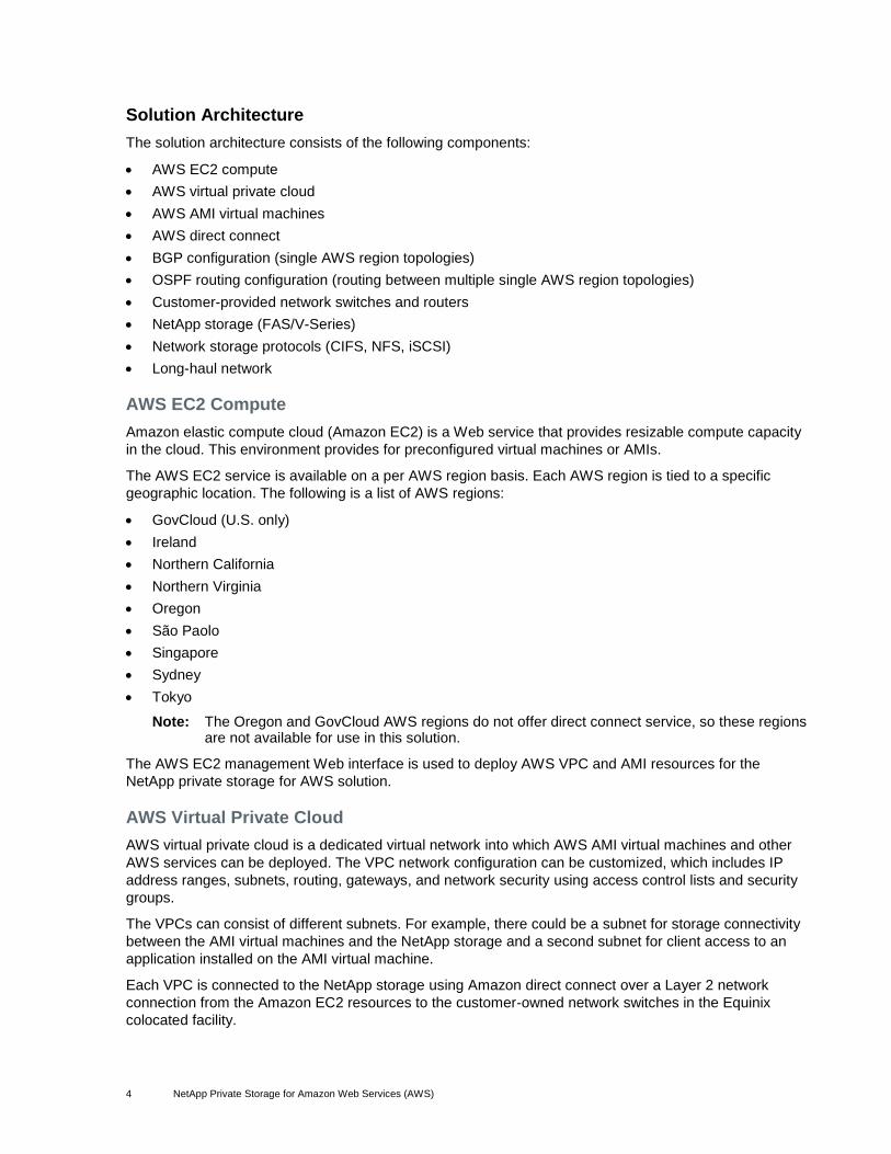
Sample Network Topologies
One of the strengths of NetApp private storage for AWS is that the solution can accommodate various
customer topologies or scenarios, although it is impossible to cover every possible topology. The
following diagrams illustrate two common routing configurations.
Figure 1) Example of routing configuration between colocated data center and EC2 virtual private cloud (BGP only).

8 NetApp Private Storage for Amazon Web Services (AWS)
Figure 2) Example of complex routing configuration, including routing over private network between EC2 regions to support SnapMirror replication between colocated data centers (BGP and OSPF).
9 NetApp Private Storage for Amazon Web Services (AWS)
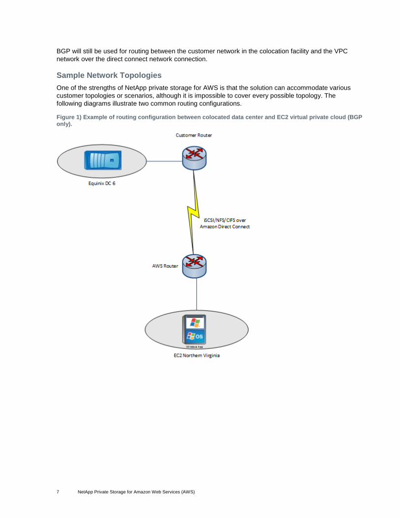
NetApp Private Storage for AWS Deployment Guide
Table 1) NetApp private storage for AWS prerequisites.
Description
The customer must have an Amazon account created with an associated payment method and must have associated this account with Amazon Web services (http://aws.amazon.com).
Designate in which Amazon AWS region Amazon EC2 AMI virtual machines will be stored.
Identify the availability zones in the designated AWS region where AMI virtual machines will be created.
IP address plan for VPC (IP CIDR block and subnet information).
NetApp storage controller must be installed in the colocation facility for the designated Amazon AWS region.
Customer-provided network switch(es) and router(s) must be installed in the colocation facility for the designated Amazon AWS region.
Customer-provided network router(s) must have BGP support enabled.
Determine which type of AMI virtual machine will be deployed in EC2 for the solution.
NetApp storage system network interfaces connected to the customer-provided network switch(es).
NetApp storage system network interfaces enabled and configured.

10 NetApp Private Storage for Amazon Web Services (AWS)
Create and Configure Amazon AWS Virtual Private Cloud
To create and configure an Amazon AWS virtual private cloud, complete the following steps:
1. Open a Web browser and go to the URL for Amazon AWS, http://aws.amazon.com. Click “Sign in to the AWS Console” to access the AWS console.
11 NetApp Private Storage for Amazon Web Services (AWS)
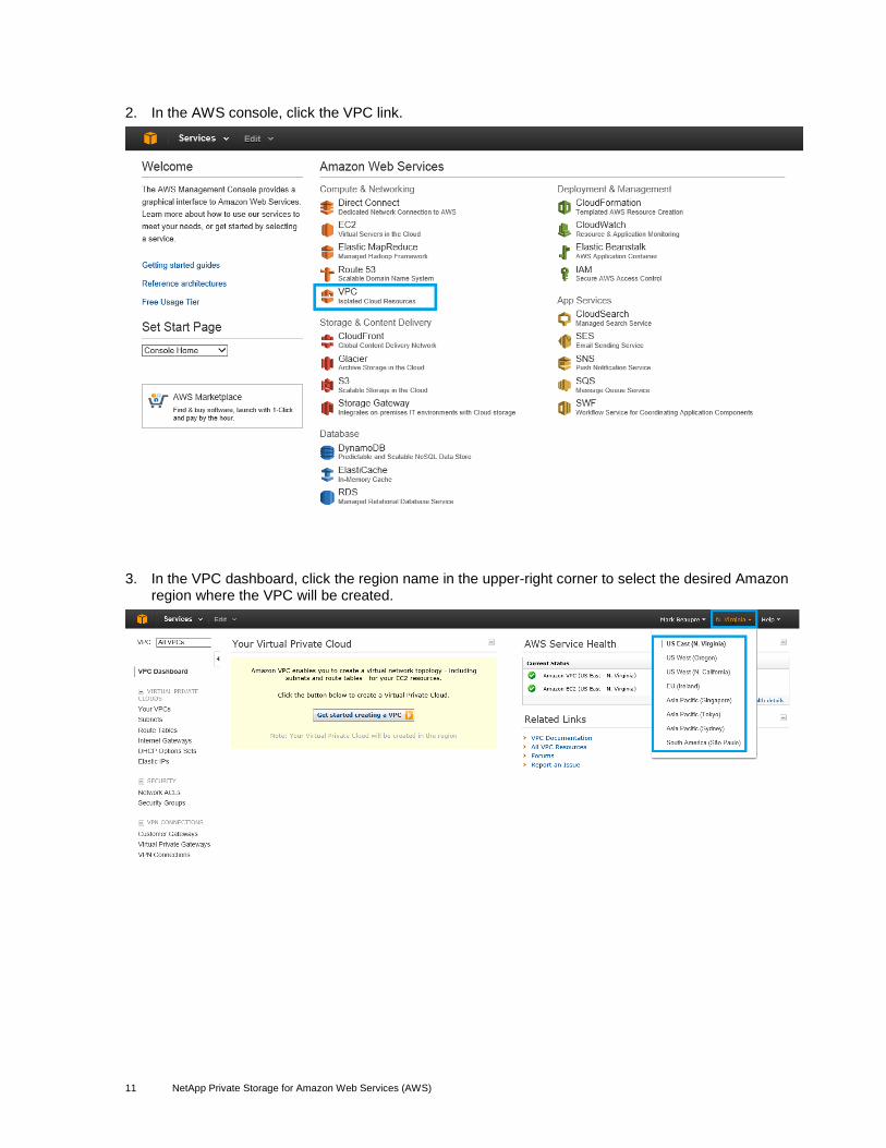
2. In the AWS console, click the VPC link.
3. In the VPC dashboard, click the region name in the upper-right corner to select the desired Amazon region where the VPC will be created.

12 NetApp Private Storage for Amazon Web Services (AWS)
4. After selecting the Amazon region in the VPC console, click “Get started to creating a VPC.”

13 NetApp Private Storage for Amazon Web Services (AWS)
5. In the “Create an Amazon Private Cloud” wizard, select “VPC with Public and Private Subnets.”
Note: The option “VPC with Public and Private Subnets” will allow for a network configuration that will support LAN access to the EC2 AMI virtual machines and a private storage connection between the NetApp storage and the EC2 AMI virtual machines.
Note: Other VPC subnet options can be selected based on the requirements where the solution will be used.
Click Continue.

14 NetApp Private Storage for Amazon Web Services (AWS)
6. In the “Create an Amazon Virtual Cloud” page, set the following options for your environment:
“Edit VPC CIDR IP Block” to set the CIDR IP block for the VPC network (that is, 10.0.10.0/16).
“Edit Public Subnet” to set the public subnet in the CIDR IP block (that is, 10.0.10.0/24).
“Edit Private Subnet” to set the private subnet in the CIDR IP block (that is, 10.0.11.0/24).
“Edit NAT Instance Type” to set the EC2 AMI instance type. (that is, m1.large).
Note: Your instance type will depend on the system requirements of the applications that will be run on the EC2 AMI instances.
Note: An AMI instance will automatically be created and assigned to the VPC.
Set hardware tenancy, if desired.
Click “Create VPC.”
7. You will be notified of the successful creation of the VPC. Click Close.

15 NetApp Private Storage for Amazon Web Services (AWS)
8. In the VPC dashboard, click Subnets to review the subnet status.
9. In the VPC dashboard, review the subnets that have been created with the VPC. If additional subnets need to be created, for the VPC, click the “Create Subnet” link.

16 NetApp Private Storage for Amazon Web Services (AWS)
10. In the VPC dashboard, click the “Route Tables” link to review the route tables for the subnets in the VPC. If additional route tables need to be created, for the VPC, click the “Create Route Table” link.

17 NetApp Private Storage for Amazon Web Services (AWS)
11. In the VPC dashboard, click “Internet Gateways” to review the Internet gateways configured for the VPC. An Internet gateway is the router on the AWS network that connects your VPC to the Internet.
18 NetApp Private Storage for Amazon Web Services (AWS)
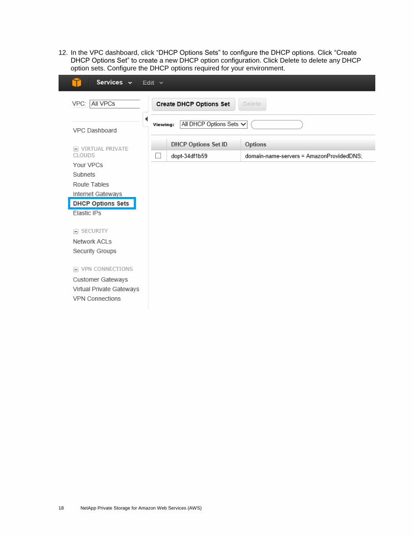
12. In the VPC dashboard, click “DHCP Options Sets” to configure the DHCP options. Click “Create DHCP Options Set” to create a new DHCP option configuration. Click Delete to delete any DHCP option sets. Configure the DHCP options required for your environment.
19 NetApp Private Storage for Amazon Web Services (AWS)
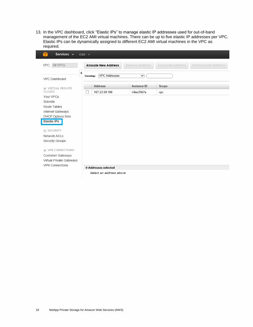
13. In the VPC dashboard, click “Elastic IPs” to manage elastic IP addresses used for out-of-band management of the EC2 AMI virtual machines. There can be up to five elastic IP addresses per VPC. Elastic IPs can be dynamically assigned to different EC2 AMI virtual machines in the VPC as required.
20 NetApp Private Storage for Amazon Web Services (AWS)
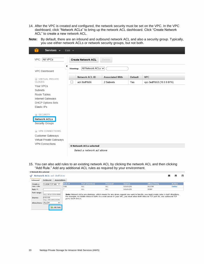
14. After the VPC is created and configured, the network security must be set on the VPC. In the VPC dashboard, click “Network ACLs” to bring up the network ACL dashboard. Click “Create Network ACL” to create a new network ACL.
Note: By default, there are an inbound and outbound network ACL and also a security group. Typically, you use either network ACLs or network security groups, but not both.
15. You can also add rules to an existing network ACL by clicking the network ACL and then clicking “Add Rule.” Add any additional ACL rules as required by your environment.

21 NetApp Private Storage for Amazon Web Services (AWS)
16. If the use of network security groups is required, click “Security Groups” in the VPC dashboard to bring up the security groups dashboard. Click “Create Security Group” to create a new security group.
17. You can also add rules to an existing network security group by clicking the security group and then clicking either the Inbound or Outbound tab. Click “Add Rule” to add any additional security rules as required by your environment.

22 NetApp Private Storage for Amazon Web Services (AWS)
Create Amazon Direct Connect Network Connection
1. Launch the direct connect network dashboard by clicking Services > Compute & Networking > Direct Connect.
2. Click the “Get Started” button to start the direct connect wizard.
23 NetApp Private Storage for Amazon Web Services (AWS)
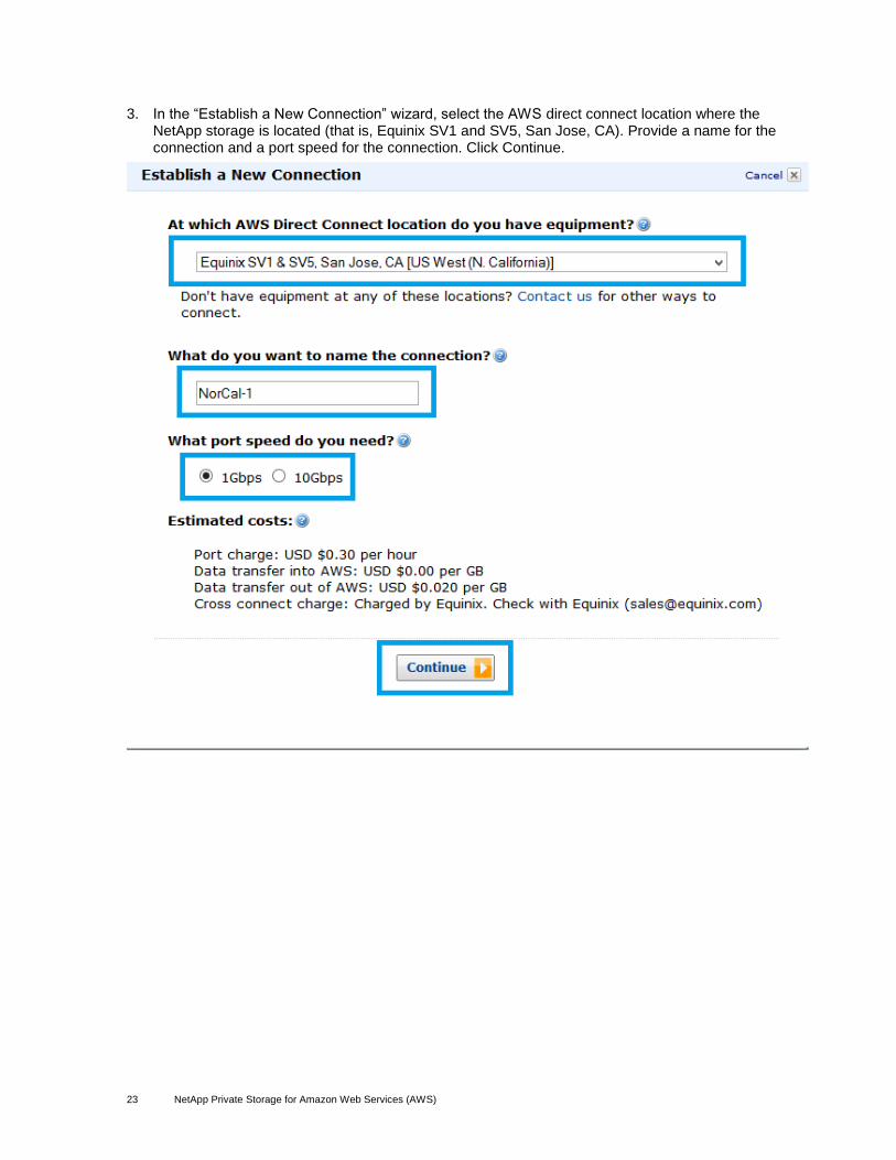
3. In the “Establish a New Connection” wizard, select the AWS direct connect location where the NetApp storage is located (that is, Equinix SV1 and SV5, San Jose, CA). Provide a name for the connection and a port speed for the connection. Click Continue.

24 NetApp Private Storage for Amazon Web Services (AWS)
4. Review the direct connect connection order details. Click Place Order.
5. Verify that the new order is listed in the order new connection dashboard.

25 NetApp Private Storage for Amazon Web Services (AWS)
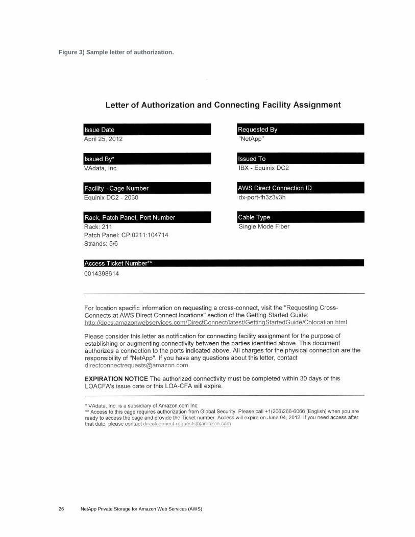
6. Follow the procedures listed in the AWS direct connect user guide, http://docs.amazonwebservices.com/directconnect/latest/UserGuide/Colocation.html, to request a cross-connect (LOA-CFA). Each location has different procedures for requesting a cross-connect. This request will create a ticket to the colocation provider so that they can physically wire the cross-connect between AWS and the router in the cage where the NetApp storage is located. Figure 3 shows a sample letter of authorization and connecting facility assignment (LOA-CFA).
26 NetApp Private Storage for Amazon Web Services (AWS)
Figure 3) Sample letter of authorization.

27 NetApp Private Storage for Amazon Web Services (AWS)
7. In addition to the LOA-CFA, provide the following information to the colocation provider:
A pair of private IP addresses in the 169.xxx.xxx.xxx range to use for the routing interfaces
The virtual gateway ID (VGW-ID) of the VPC you want to connect using this direct connect link
A pair of private autonomous system numbers (ASNs) for the connection
Note: If you use a public ASN, make sure that you own the ASN. For private ASNs, make sure that they are unique.
A VLAN ID for traffic routed to and from AWS
BGP secret configuration information
8. In the VPC dashboard, click “Internet Gateways” to view the virtual gateway ID (VGW-ID) configured for the VPC. Document the VGW-ID as you will need to provide this to the colocation provider.
Note: An Internet gateway is the router on the AWS network that connects your VPC to the Internet.

28 NetApp Private Storage for Amazon Web Services (AWS)
9. Repeat steps 1 through 8 for each additional virtual private cloud. Each virtual private cloud will be listed in the VPC dashboard.
Configure Network Router (BGP) in Colocation Facility
1. After the direct connect cross-connect has been patched, open the AWS management console and click the direct connect link to launch the direct connect dashboard.
2. In the direct connect dashboard, click the direct connect connection ID checkbox. Click the “Download Router Configuration” link.
29 NetApp Private Storage for Amazon Web Services (AWS)
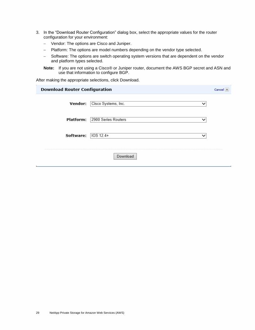
3. In the “Download Router Configuration” dialog box, select the appropriate values for the router configuration for your environment:
Vendor: The options are Cisco and Juniper.
Platform: The options are model numbers depending on the vendor type selected.
Software: The options are switch operating system versions that are dependent on the vendor and platform types selected.
Note: If you are not using a Cisco® or Juniper router, document the AWS BGP secret and ASN and use that information to configure BGP.
After making the appropriate selections, click Download.

30 NetApp Private Storage for Amazon Web Services (AWS)
4. Save the AWS direct connect router configuration to a text file. The text file will contain the ASN and BGP secret used by the AWS direct connect router. Open the file in a text editor. The following is a sample BGP router configuration for a Cisco 2900+ router running Cisco IOS® Software 12.4+:
! Amazon Web Services
! Direct Connect
! Virtual Interface ID: dxvif-ffwgp6t2
!
! --------------------------------------------------------------------------------
! Interface Configuration
interface GigabitEthernet0/1
no ip address
interface GigabitEthernet0/1.3
description "Direct Connect to your Amazon VPC or AWS Cloud"
encapsulation dot1Q 3
ip address 169.254.253.18 255.255.255.252
! --------------------------------------------------------------------------------
! Border Gateway Protocol (BGP) Configuration
!
! BGP is used to exchange prefixes between the Direct Connect Router and your
! Customer Gateway.
!
! Your Customer Gateway may announce a default route (0.0.0.0/0),
! which can be done with the 'network' and 'default-originate' statements.
!
! To advertise additional prefixes, copy the 'network' statement and identify the
! prefix you wish to advertise. Make sure the prefix is present in the routing
! table of the device with a valid next-hop.
!
! The local BGP Autonomous System Number (ASN) (64514) is configured as
! part of your Customer Gateway. If the ASN must be changed, the Customer Gateway
! and Direct Connect Virtual Interface will need to be recreated with AWS.
router bgp 64514
neighbor 169.254.253.17 remote-as 7224
neighbor 169.254.253.17 password xxxxxxxxxxxxxxxxxxxxxxx
network 0.0.0.0
exit
! Additional Notes and Questions
! - Amazon Web Services Direct Connect Getting Started Guide:
! http://docs.amazonwebservices.com/DirectConnect/latest/GettingStartedGuide/Welcome.html

31 NetApp Private Storage for Amazon Web Services (AWS)
5. On the network router, configure BGP to advertise routes to AWS and receive BGP advertisements from AWS.
Note: BGP relies on autonomous system numbers to identify networks for routing purposes. The customer-provided router in the colocation facility is assigned an AS number. This number must be unique and not conflict with any reserved AS numbers that Amazon uses. Use the BGP configuration information from the router configuration downloaded from the direct connect dashboard and apply this configuration to the customer-provided router.
Note: The following is a sample configuration for a Cisco 2900 router. Note the BGP configuration section:
POC-4908-SV#show run
Building configuration...
Current configuration:
!
version 12.0
no service pad
service timestamps debug uptime
service timestamps log uptime
no service password-encryption
!
hostname POC-4908-SV
!
enable secret 5 xxxxxxxxxxxxxxxxxxxxxxxxxxxxx
enable password xxxxxx
!
ip subnet-zero
bridge irb
!
!
!
interface GigabitEthernet1
no ip address
no ip directed-broadcast
no negotiation auto
!
interface GigabitEthernet1.10
encapsulation dot1Q 10
no ip directed-broadcast
bridge-group 10
!
interface GigabitEthernet1.11
encapsulation dot1Q 11
no ip directed-broadcast
bridge-group 11
!
interface GigabitEthernet1.12
encapsulation dot1Q 12
no ip directed-broadcast
bridge-group 12
!
interface GigabitEthernet2
no ip address
no ip directed-broadcast
!
interface GigabitEthernet2.1
encapsulation dot1Q 3
no ip directed-broadcast
bridge-group 2
!
interface GigabitEthernet3
no ip address
no ip directed-broadcast
!
interface GigabitEthernet4
no ip address
no ip directed-broadcast
shutdown

32 NetApp Private Storage for Amazon Web Services (AWS)
!
interface GigabitEthernet5
no ip address
no ip directed-broadcast
shutdown
!
interface GigabitEthernet6
no ip address
no ip directed-broadcast
shutdown
!
interface GigabitEthernet7
no ip address
no ip directed-broadcast
no negotiation auto
!
interface GigabitEthernet7.1
encapsulation dot1Q 3
ip address 169.254.253.18 255.255.255.252
no ip directed-broadcast
!
interface GigabitEthernet8
no ip address
no ip directed-broadcast
no negotiation auto
!
interface GigabitEthernet8.3
encapsulation dot1Q 3
no ip directed-broadcast
bridge-group 2
!
interface GigabitEthernet8.10
encapsulation dot1Q 10
no ip directed-broadcast
bridge-group 10
!
interface GigabitEthernet8.11
encapsulation dot1Q 11
no ip directed-broadcast
bridge-group 11
!
interface GigabitEthernet8.12
encapsulation dot1Q 12
no ip directed-broadcast
bridge-group 12
!
interface BVI2
ip address 192.168.1.100 255.255.255.0
no ip directed-broadcast
no ip route-cache cef
!
interface BVI3
no ip address
no ip directed-broadcast
no ip route-cache cef
shutdown
!
interface BVI10
ip address 10.10.10.4 255.255.255.0
no ip directed-broadcast
no ip route-cache cef
!
interface BVI11
ip address 10.10.11.4 255.255.255.0
no ip directed-broadcast
no ip route-cache cef
!
interface BVI12
ip address 10.10.12.4 255.255.255.0
no ip directed-broadcast
no ip route-cache cef

33 NetApp Private Storage for Amazon Web Services (AWS)
!
router bgp 64514
network 10.10.10.0 mask 255.255.255.0
network 192.168.1.0
neighbor 169.254.253.17 remote-as 7224
neighbor 169.254.253.17 password xxxxxxxxxxxxxxxxxxxxxxxx
!
ip classless
!
6. After the direct connect connection is established and the BGP configuration is set up, the status of the direct connect connection will change to green in the direct connect dashboard.
7. Repeat steps 1 through 6 for each additional direct connect connection. Each direct connect connection will be listed in the direct connect dashboard.
Create AWS AMI Virtual Machines
1. Launch the EC2 dashboard by clicking Services > Compute & Networking > EC2.

34 NetApp Private Storage for Amazon Web Services (AWS)
2. In the EC2 dashboard, click “Launch Instance” to start the “Create a New Instance” wizard. Select the Wizard option (that is, Classic Wizard) and click Continue.
35 NetApp Private Storage for Amazon Web Services (AWS)
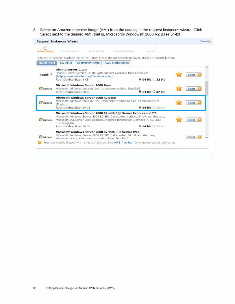
3. Select an Amazon machine image (AMI) from the catalog in the request instances wizard. Click Select next to the desired AMI (that is, Microsoft® Windows® 2008 R2 Base 64-bit).
36 NetApp Private Storage for Amazon Web Services (AWS)
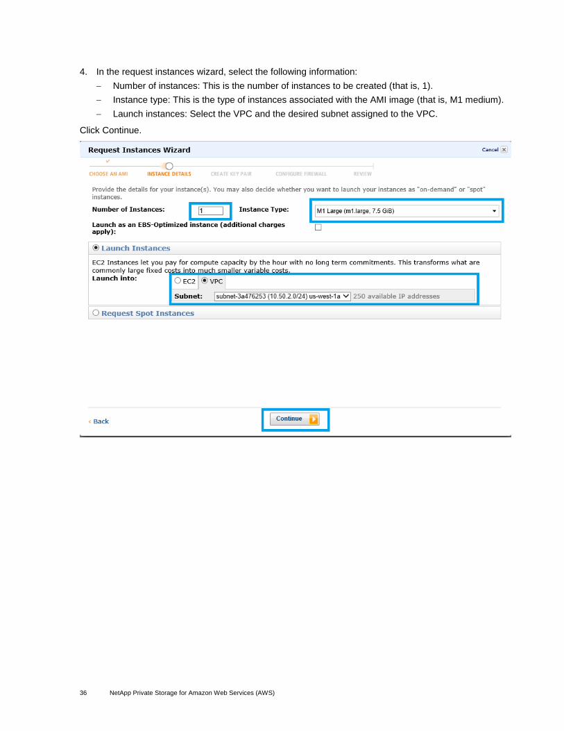
4. In the request instances wizard, select the following information:
Number of instances: This is the number of instances to be created (that is, 1).
Instance type: This is the type of instances associated with the AMI image (that is, M1 medium).
Launch instances: Select the VPC and the desired subnet assigned to the VPC.
Click Continue.

37 NetApp Private Storage for Amazon Web Services (AWS)
5. Under the “Advanced Instance Options,” set CloudWatch monitoring for the instance, User Data describing the instance, termination protection, and shutdown behavior. Select the number of network interfaces for the instance (that is, 2).
Note: It is recommended to have separate interfaces for storage and LAN access. Each interface will have a separate subnet and IP address assigned to it.
Note: For redundant iSCSI connectivity to the NetApp storage, configure multiple direct connect connections. Each iSCSI session would use a different direct connect network connection.
Click Continue.

38 NetApp Private Storage for Amazon Web Services (AWS)
6. In “Storage Device Configuration,” click Edit to set storage options for the AMI instance.
Note: If you click Edit, you can set the size of the root volume for the instance, set the volume type, and assign Amazon EBS storage and instance store volumes.
After setting the desired instance storage options, click Continue.

39 NetApp Private Storage for Amazon Web Services (AWS)
7. If desired, create metadata tags to simplify the administration of your AMI instances. The tags consist of user-friendly names that help organize and browse resources. Enter in a key (that is, Windows) and a value (2008 R2). Click Continue.
40 NetApp Private Storage for Amazon Web Services (AWS)
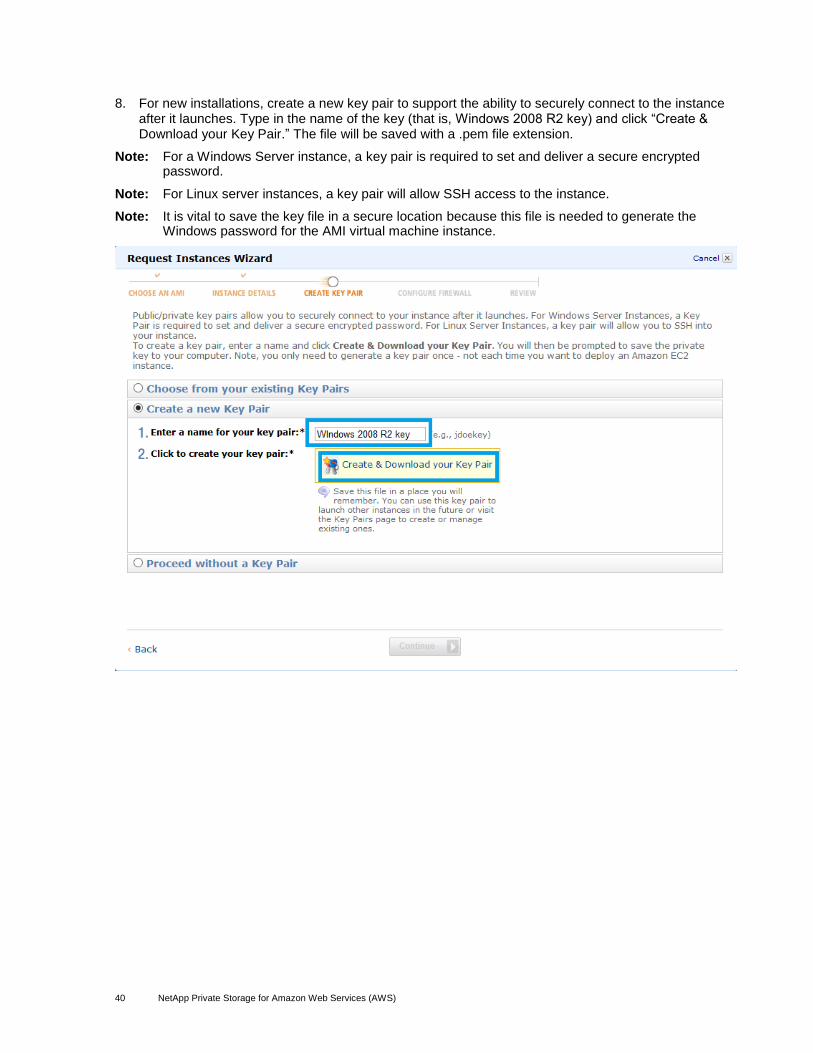
8. For new installations, create a new key pair to support the ability to securely connect to the instance after it launches. Type in the name of the key (that is, Windows 2008 R2 key) and click “Create & Download your Key Pair.” The file will be saved with a .pem file extension.
Note: For a Windows Server instance, a key pair is required to set and deliver a secure encrypted password.
Note: For Linux server instances, a key pair will allow SSH access to the instance.
Note: It is vital to save the key file in a secure location because this file is needed to generate the Windows password for the AMI virtual machine instance.

41 NetApp Private Storage for Amazon Web Services (AWS)
9. For existing configurations, select “Choose from your existing Key Pairs.” Select the preexisting key pair from the “Your existing Key Pairs” dropdown list. After selecting the existing key pair, click Continue.

42 NetApp Private Storage for Amazon Web Services (AWS)
10. For new installations, select an existing network security group created when the VPC was created, or create a new network security group. If you create a new security group, you will set the group name, group description, and inbound rules to the instance. After selecting the security group options, click Continue.

43 NetApp Private Storage for Amazon Web Services (AWS)
11. Review the instance details prior to launch. Edit any details that are not correct. Click Launch to continue.
12. After the launch of the instance is initiated, you can create a status check alarm or add AWS EBS volumes to the instance. Click Close to complete the wizard.

44 NetApp Private Storage for Amazon Web Services (AWS)
13. The EC2 dashboard will show the new AMI instance that was created.to verify that the instance was created. Click the Tag field for the new AMI instance to assign a tag to the new AMI instance. Click Save to save the changes.
14. In the EC2 dashboard, right click the instance name, and select Get Windows Password.
Note: AWS requires that you wait at least 15 minutes after launching an instance for the first time before attempting to retrieve the local administrator password for the instance.

45 NetApp Private Storage for Amazon Web Services (AWS)
15. In the Retrieve Windows Administrator Password dialog box, copy the contents from the .pem key pair file that is being used by the instance into the Private Key field. Click “Decrypt Password” to retrieve the local password for the AMI virtual machine instance.

46 NetApp Private Storage for Amazon Web Services (AWS)
16. If the key pair information is correct, the local administrator password will be shown.
Note: It is recommended to change the password.
Click Close.

47 NetApp Private Storage for Amazon Web Services (AWS)
17. In the EC2 dashboard, click Elastic IPs to launch the elastic IP dashboard. If less than 5 elastic IP addresses have been allocated for the VPC, click the Allocate IP Address link.
18. In the Allocate New Address dialog box, select VPC from the dropdown box. Click “Yes, Allocate” to continue.

48 NetApp Private Storage for Amazon Web Services (AWS)
19. Click the allocated elastic IP address and then click Associate Address.

49 NetApp Private Storage for Amazon Web Services (AWS)
20. In the Associate Address dialog box, select the instance that was created and the IP address for the interface with which the elastic IP address will be associated.
Note: Alternatively, you can associate by interface name.
Click “Yes, Associate” to continue.

50 NetApp Private Storage for Amazon Web Services (AWS)
21. Review the elastic IP dashboard to show that the elastic IP has been associated with the AMI virtual machine instance.
22. From a Windows host connected to the Internet, open the remote desktop (RDP) client. Provide the elastic IP address, the administrator user name, and password for the new AMI virtual machine instance and log into the virtual machine.
23. Repeat steps 1 through 22 for any additional AMI instances that will be needed.
51 NetApp Private Storage for Amazon Web Services (AWS)
NetApp Private Cloud for AWS OSPF Deployment Guide
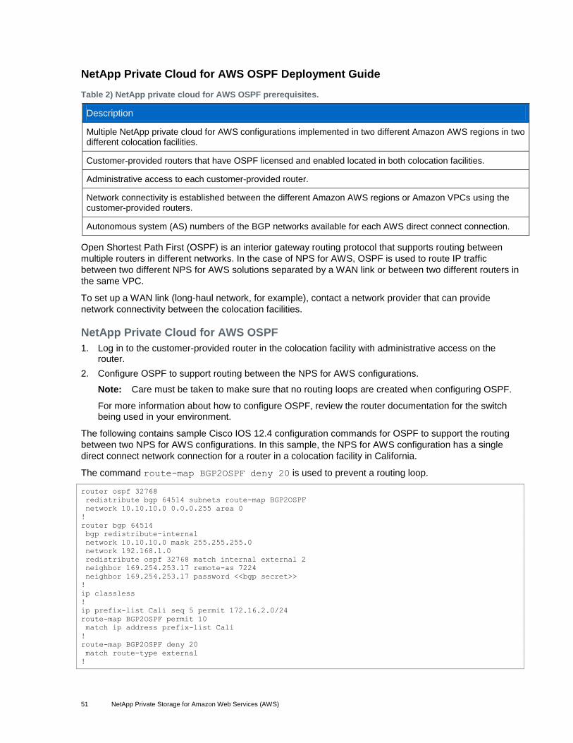
Table 2) NetApp private cloud for AWS OSPF prerequisites.
Description
Multiple NetApp private cloud for AWS configurations implemented in two different Amazon AWS regions in two different colocation facilities.
Customer-provided routers that have OSPF licensed and enabled located in both colocation facilities.
Administrative access to each customer-provided router.
Network connectivity is established between the different Amazon AWS regions or Amazon VPCs using the customer-provided routers.
Autonomous system (AS) numbers of the BGP networks available for each AWS direct connect connection.
Open Shortest Path First (OSPF) is an interior gateway routing protocol that supports routing between
multiple routers in different networks. In the case of NPS for AWS, OSPF is used to route IP traffic
between two different NPS for AWS solutions separated by a WAN link or between two different routers in
the same VPC.
To set up a WAN link (long-haul network, for example), contact a network provider that can provide
network connectivity between the colocation facilities.
NetApp Private Cloud for AWS OSPF
1. Log in to the customer-provided router in the colocation facility with administrative access on the router.
2. Configure OSPF to support routing between the NPS for AWS configurations.
Note: Care must be taken to make sure that no routing loops are created when configuring OSPF.
For more information about how to configure OSPF, review the router documentation for the switch being used in your environment.
The following contains sample Cisco IOS 12.4 configuration commands for OSPF to support the routing
between two NPS for AWS configurations. In this sample, the NPS for AWS configuration has a single
direct connect network connection for a router in a colocation facility in California.
The command route-map BGP2OSPF deny 20 is used to prevent a routing loop.
router ospf 32768
redistribute bgp 64514 subnets route-map BGP2OSPF
network 10.10.10.0 0.0.0.255 area 0
!
router bgp 64514
bgp redistribute-internal
network 10.10.10.0 mask 255.255.255.0
network 192.168.1.0
redistribute ospf 32768 match internal external 2
neighbor 169.254.253.17 remote-as 7224
neighbor 169.254.253.17 password <<bgp secret>>
!
ip classless
!
ip prefix-list Cali seq 5 permit 172.16.2.0/24
route-map BGP2OSPF permit 10
match ip address prefix-list Cali
!
route-map BGP2OSPF deny 20
match route-type external
!

52 NetApp Private Storage for Amazon Web Services (AWS)
3. Repeat steps 1 and 2 for each additional NPS for AWS configuration.
The following contains sample Cisco IOS 12.4 configuration commands for OSPF to support the routing
between two NPS for AWS configurations. In this sample, the NPS for AWS configuration has a single
direct connect network connection for a router in a colocation facility in Virginia.
The command route-map BGP2OSPF deny 20 is used to prevent a routing loop.
router ospf 32769
redistribute bgp 64513 subnets route-map BGP2OSPF
network 10.10.10.0 0.0.0.255 area 0
!
router bgp 64513
bgp redistribute-internal
network 10.10.10.0 mask 255.255.255.0
network 10.10.10.0
network 192.168.1.0
redistribute ospf 32769 match internal external 2
neighbor 169.254.255.57 remote-as 7224
neighbor 169.254.255.57 password <<bgp secret>>
!
ip classless
!
ip prefix-list Virginia seq 5 permit 172.16.1.0/24
route-map BGP2OSPF permit 10
match ip address prefix-list Virginia
!
route-map BGP2OSPF deny 20
match route-type external
!

53 NetApp Private Storage for Amazon Web Services (AWS)
NetApp Private Storage for AWS BPG Test Procedures
Verify Direct Connect Network Connections
Test Case Details
Test Number NPSAWSBPG-1
Tester
Date
Test Prerequisites The physical network connectivity from AWS EC2 to the NetApp storage using an AWS direct connect network connection has been established.
Network interface configuration for the NetApp storage has been configured to use the AWS direct connect network connection.
The AMI virtual machine instance is up and running.
The AMI virtual machine instance is configured with a virtual network interface to communicate to the NetApp storage.
Local administrator access to the AMI virtual machine instance.
BGP configuration on the customer-provided router in the colocation facility.
The direct connect network rules allow ICMP ping to the AMI virtual machine instances.
An AWS elastic IP address is assigned to the AMI virtual machine for out-of-band access to the virtual machine.
Expected Outcome The ping test succeeds (0% packet loss), and network information is displayed.
Test Results Passed/failed
Comments
Test Procedure
1. Log into the AWS management console. In the VPC dashboard, click “Elastic IPs” to manage elastic IP addresses used for out-of-band management of the EC2 AMI virtual machines. There can be up to five elastic IP addresses per VPC. Elastic IPs can be dynamically assigned to different EC2 AMI virtual machines in the VPC as required.
54 NetApp Private Storage for Amazon Web Services (AWS)
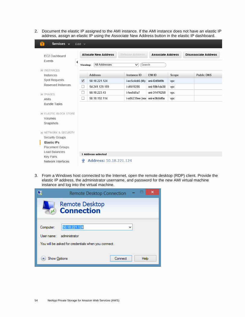
2. Document the elastic IP assigned to the AMI instance. If the AMI instance does not have an elastic IP address, assign an elastic IP using the Associate New Address button in the elastic IP dashboard.
3. From a Windows host connected to the Internet, open the remote desktop (RDP) client. Provide the elastic IP address, the administrator username, and password for the new AMI virtual machine instance and log into the virtual machine.
55 NetApp Private Storage for Amazon Web Services (AWS)
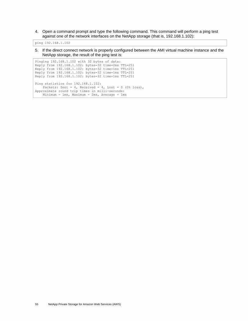
4. Open a command prompt and type the following command. This command will perform a ping test against one of the network interfaces on the NetApp storage (that is, 192.168.1.102):
ping 192.168.1.102
5. If the direct connect network is properly configured between the AMI virtual machine instance and the NetApp storage, the result of the ping test is:
Pinging 192.168.1.102 with 32 bytes of data:
Reply from 192.168.1.102: bytes=32 time=2ms TTL=251
Reply from 192.168.1.102: bytes=32 time=1ms TTL=251
Reply from 192.168.1.102: bytes=32 time=1ms TTL=251
Reply from 192.168.1.102: bytes=32 time=1ms TTL=251
Ping statistics for 192.168.1.102:
Packets: Sent = 4, Received = 4, Lost = 0 (0% loss),
Approximate round trip times in milli-seconds:
Minimum = 1ms, Maximum = 2ms, Average = 1ms

56 NetApp Private Storage for Amazon Web Services (AWS)
NetApp Private Storage for AWS OSPF Test Procedures
Verify Routing Across WAN
Test Case Details
Test Number NPSAWSOSPF-1
Tester
Date
Test Prerequisites NetApp private storage for AWS solution has been installed and configured in two different colocation facilities and two different Amazon AWS regions.
The long-haul network (MPLS)/VPN connectivity between the two NetApp private storage for AWS solutions has been established.
Two AMI virtual machine instances are up and running. Each AMI is in different VPCs in different AWS regions.
The AMI virtual machine instance is configured with at least one virtual network interface.
Local administrator access to the AMI virtual machines.
OSPF configuration on the customer-provided router in both colocation facilities.
An AWS elastic IP address is assigned to each AMI virtual machine for out-of-band access to the virtual machines.
Expected Outcome The ping test succeeds (0% packet loss), and network information is displayed.
Test Results Passed/failed
Comments
Test Procedure
1. Log into the AWS management console and select the primary region. In the VPC dashboard, click “Elastic IPs” to manage elastic IP addresses used for out-of-band management of the EC2 AMI virtual machines. There can be up to five elastic IP addresses per VPC. Elastic IPs can be dynamically assigned to different EC2 AMI virtual machines in the VPC as required.

57 NetApp Private Storage for Amazon Web Services (AWS)
2. Document the elastic IP assigned to the AMI instance. If the AMI instance does not have an elastic IP address, assign an elastic IP using the Associate New Address button in the elastic IP dashboard.
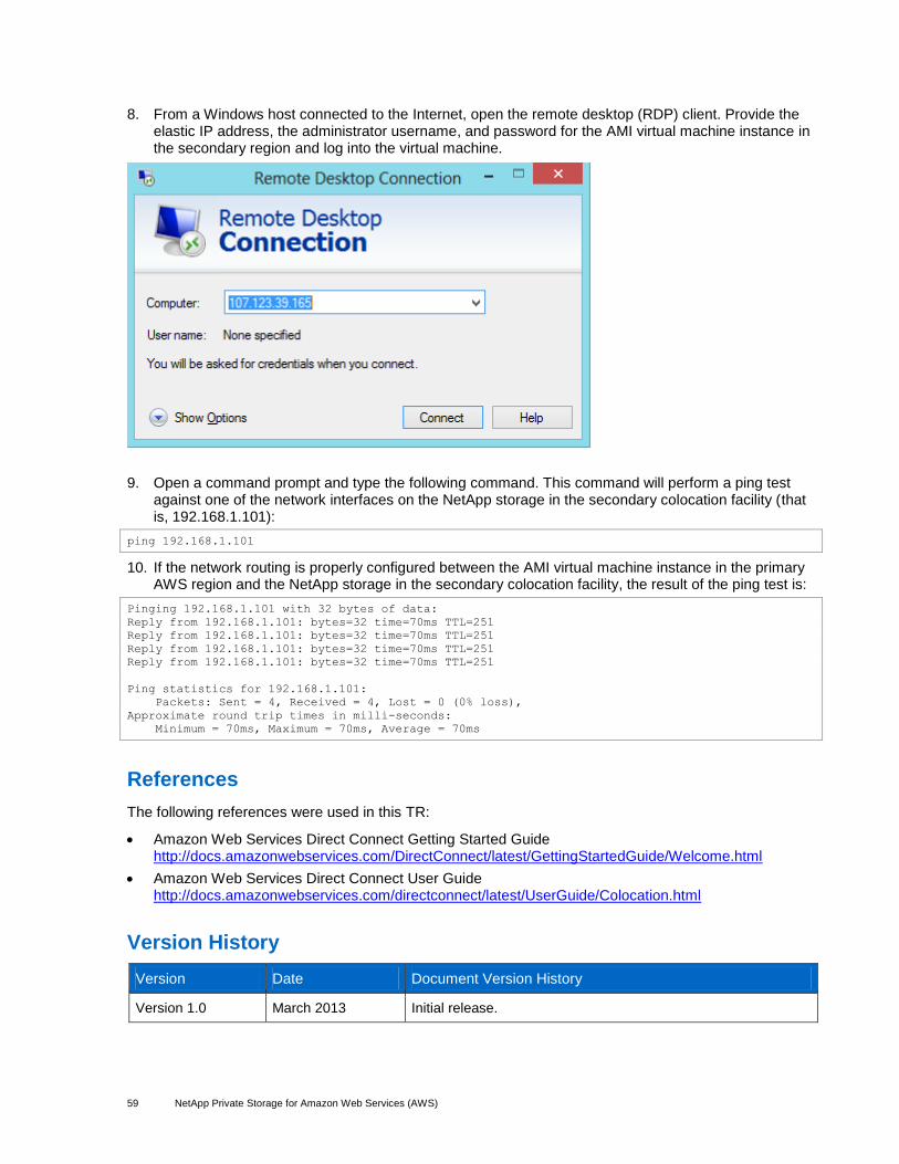
3. From a Windows host connected to the Internet, open the remote desktop (RDP) client. Provide the elastic IP address, the administrator username, and password for the AMI virtual machine instance and log into the virtual machine.

58 NetApp Private Storage for Amazon Web Services (AWS)
4. Open a command prompt and type the following command. This command will perform a ping test against one of the network interfaces on the NetApp storage in the secondary colocation facility (that is, 192.168.1.101):
ping 192.168.1.101
5. If the network routing is properly configured between the AMI virtual machine instance in the primary AWS region and the NetApp storage in the secondary colocation facility, the result of the ping test is:
Pinging 192.168.1.101 with 32 bytes of data:
Reply from 192.168.1.101: bytes=32 time=71ms TTL=251
Reply from 192.168.1.101: bytes=32 time=71ms TTL=251
Reply from 192.168.1.101: bytes=32 time=71ms TTL=251
Reply from 192.168.1.101: bytes=32 time=71ms TTL=251
Ping statistics for 192.168.1.101:
Packets: Sent = 4, Received = 4, Lost = 0 (0% loss),
Approximate round trip times in milli-seconds:
Minimum = 71ms, Maximum = 71ms, Average = 71ms
6. In the AWS management console and select the secondary region. In the VPC dashboard, click “Elastic IPs” to manage elastic IP addresses used for out-of-band management of the EC2 AMI virtual machines. There can be up to five elastic IP addresses per VPC. Elastic IPs can be dynamically assigned to different EC2 AMI virtual machines in the VPC as required.
7. Document the elastic IP assigned to the AMI instance in the secondary region. If the AMI instance does not have an elastic IP address, assign an elastic IP using the Associate New Address button in the elastic IP dashboard.
59 NetApp Private Storage for Amazon Web Services (AWS)
8. From a Windows host connected to the Internet, open the remote desktop (RDP) client. Provide the elastic IP address, the administrator username, and password for the AMI virtual machine instance in the secondary region and log into the virtual machine.
9. Open a command prompt and type the following command. This command will perform a ping test against one of the network interfaces on the NetApp storage in the secondary colocation facility (that is, 192.168.1.101):
ping 192.168.1.101
10. If the network routing is properly configured between the AMI virtual machine instance in the primary AWS region and the NetApp storage in the secondary colocation facility, the result of the ping test is:
Pinging 192.168.1.101 with 32 bytes of data:
Reply from 192.168.1.101: bytes=32 time=70ms TTL=251
Reply from 192.168.1.101: bytes=32 time=70ms TTL=251
Reply from 192.168.1.101: bytes=32 time=70ms TTL=251
Reply from 192.168.1.101: bytes=32 time=70ms TTL=251
Ping statistics for 192.168.1.101:
Packets: Sent = 4, Received = 4, Lost = 0 (0% loss),
Approximate round trip times in milli-seconds:
Minimum = 70ms, Maximum = 70ms, Average = 70ms
References
The following references were used in this TR:
Amazon Web Services Direct Connect Getting Started Guide http://docs.amazonwebservices.com/DirectConnect/latest/GettingStartedGuide/Welcome.html
Amazon Web Services Direct Connect User Guide http://docs.amazonwebservices.com/directconnect/latest/UserGuide/Colocation.html
Version History
Version Date Document Version History
Version 1.0 March 2013 Initial release.

60 NetApp Private Storage for Amazon Web Services (AWS)
NetApp provides no representations or warranties regarding the accuracy, reliability, or serviceability of any information or recommendations provided in this publication, or with respect to any results that may be obtained by the use of the information or observance of any recommendations provided herein. The information in this document is distributed AS IS, and the use of this information or the implementation of any recommendations or techniques herein is a customer’s responsibility and depends on the customer’s ability to evaluate and integrate them into the customer’s operational environment. This document and the information contained herein may be used solely in connection with the NetApp products discussed in this document.
© 2013 NetApp, Inc. All rights reserved. No portions of this document may be reproduced without prior written consent of NetApp, Inc. Specifications are subject to change without notice. NetApp, the NetApp logo, Go further, faster, Data ONTAP, SnapMirror, and SnapVault are trademarks or registered trademarks of NetApp, Inc. in the United States and/or other countries. Microsoft, Windows, and Windows Server are registered trademarks of Microsoft Corporation. Linux is a registered trademark of Linus Torvalds. Oracle is a registered trademark of Oracle Corporation. Cisco and IOS are registered trademarks of Cisco Systems, Inc. All other brands or products are trademarks or registered trademarks of their respective holders and should be treated as such. TR-4133-0313
Refer to the Interoperability Matrix Tool (IMT) on the NetApp Support site to validate that the exact product and feature versions described in this document are supported for your specific environment. The NetApp IMT defines the product components and versions that can be used to construct configurations that are supported by NetApp. Specific results depend on each customer's installation in accordance with published specifications.