Technical Reference Manual - Level measurement - …TRM) Technical...Preface ii LFXG-F Technical...
73
Technical Reference Manual LFXG-F ® FiberFlex ® Detector with Frequency Output For Continuous Level Applications Document ID: 31557 Nuclear
Transcript of Technical Reference Manual - Level measurement - …TRM) Technical...Preface ii LFXG-F Technical...
Technical Reference ManualLFXG-F®
FiberFlex® Detector with Frequency OutputFor Continuous Level Applications
Document ID:31557
Nuclear

Revision history
Table 1: Revision history
Version Description Date
1.0 Initial release. Formerly 241089. 2001
1.1 Added internal and external ground screw information. Changed format.
051201
1.2 Electronics revision 090306
1.3 Added certification information and IECex label 090819
1.4 Changed company name, logo, and website 110301
Copyright© 2011 VEGA Americas, Inc., Cincinnati, Ohio. All rights reserved.
This document contains proprietary information of VEGA Americas, Inc. It shall not be reproduced in whole or in part, in any form, without the expressed written permission of VEGA Americas, Inc.
The material in this document is provided for informational purposes and is subject to change without notice.
FiberFlex and VEGAViewTM
are trademarks of VEGA Americas, Inc.
US and Foreign Patent Pending.
HART® is a registered trademark of The HART
® Communication Foundation.
Santoprene® is a registered trademark of Advanced Elastomer Systems.
ISO 9001 approval by Lloyd’s Register Quality Assurance Limited, to the following Quality Management System Standards: ISO 9001:2000, ANSI/ASQC Q9001-2000, Approval Certificate No. 107563.
VEGA Americas, Inc.
4170 Rosslyn Drive
Cincinnati, Ohio 45209-1599 USA
Voice:
( 5 1 3 ) 2 7 2 - 0 1 3 1
FAX:
( 5 1 3 ) 2 7 2 - 0 1 3 3 Web site www.vega-americas.com
WARNING! Use this equipment only in the manner that this manual describes. If you do not
use the equipment per VEGA specifications, the unit is not CE compliant, and may be
damaged or cause personal injury.

Preface
ii LFXG-F Technical Reference Manual
Contents Explanation of symbols vii
Your comments viii
CHAPTER 1 : INTRODUCTION 1
Nuclear materials notice 1
Unpacking the equipment 2
Storing the equipment 3
Certifications 3
LXFG-F specifications 5
Typical applications 6
Where to find help 7
VEGA Customer Service 7
Principle of operation 8
System overview 8
Scintillator model LXFG-F 10
Communicating with the gauge 11
CHAPTER 2 : INSTALLATION 13
Location considerations 13
Mounting the measuring assembly 15
Wiring the equipment 16
Power 19
Switch for CE compliance 19
SmartPro and ProPac connections 19
Conduit 19
Commissioning the gauge 20
Can you remove the source holder lock? 21
Field service commissioning call checklist 22
CHAPTER 3 : CALIBRATION 23
Memory backup 24
Calibration with SmartPro 25
Choosing the calibration method 25
Two-point calibration 26
Set process span 26
Cal Lo on Process 27
Cal Hi on Process 29
Calculate calibration with Two Point Cal 31
Creating a linearizer curve (optional) 32
Manually entering Cal High and Cal Low counts (optional) 33
Entering and activating the linearizer curve 34
When a two-point initial calibration is impossible 35
When a new calibration may be necessary 35
Periodic re-cal 36
CHAPTER 4 : DIAGNOSTICS AND REPAIR 39
Software diagnostics 39
Hardware diagnostics 39
Test points 40
Jumpers 41
LED indicators 41
Maintenance and repair 43
Periodic maintenance schedule 43
Spare parts 43
Replacing the CPU or power supply board 45
Requesting field service 47
Returning equipment for repair to VEGA 47

Preface
LFXG-F Technical Reference Manual iii
APPENDIX I: SPECIAL APPLICATIONS 49
Multiple detectors summation 50
Jumpers to reduce counts 52
Initial settings and calibration requirements 52
Vapor pressure compensation 53
Installation requirements 54
Detector wiring 55
Initial settings and calibration requirements 55
Pressure compensation fine tuning 56
Internal heater kit for applications as lows as –50 °°°°C 58
INDEX 59
Preface
iv LFXG-F Technical Reference Manual
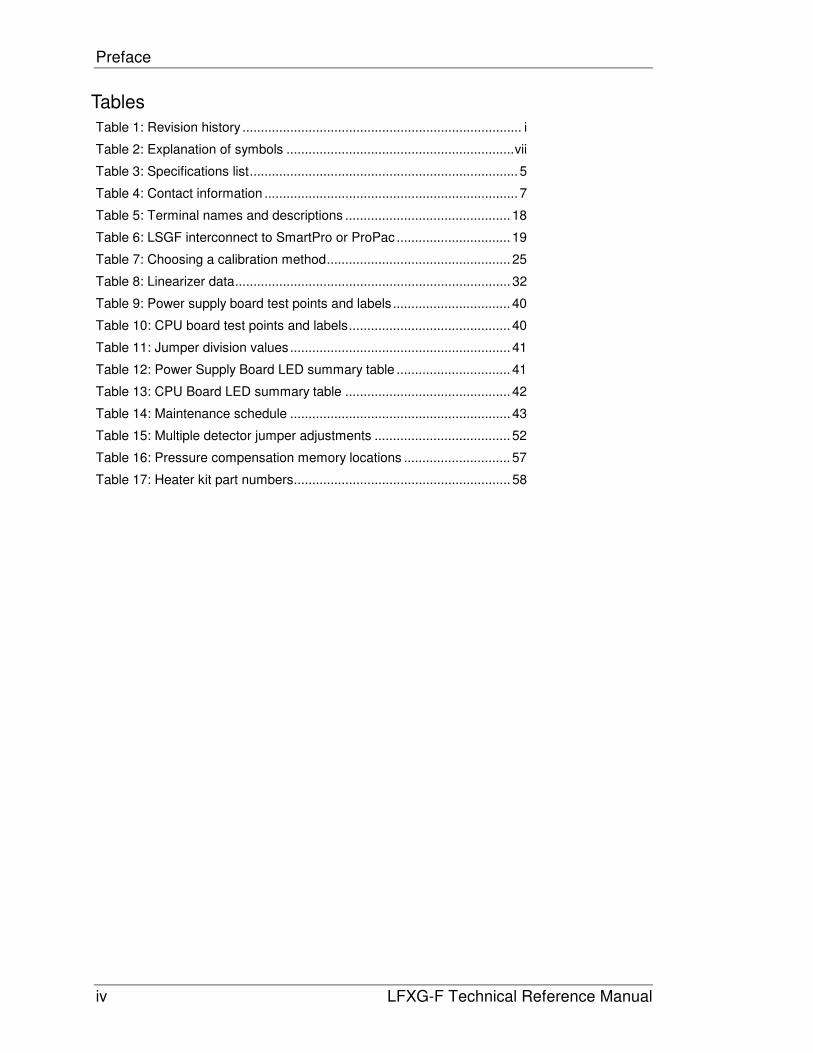
Tables
Table 1: Revision history ............................................................................ i
Table 2: Explanation of symbols .............................................................. vii
Table 3: Specifications list ......................................................................... 5
Table 4: Contact information ..................................................................... 7
Table 5: Terminal names and descriptions ............................................. 18
Table 6: LSGF interconnect to SmartPro or ProPac ............................... 19
Table 7: Choosing a calibration method .................................................. 25
Table 8: Linearizer data ........................................................................... 32
Table 9: Power supply board test points and labels ................................ 40
Table 10: CPU board test points and labels ............................................ 40
Table 11: Jumper division values ............................................................ 41
Table 12: Power Supply Board LED summary table ............................... 41
Table 13: CPU Board LED summary table ............................................. 42
Table 14: Maintenance schedule ............................................................ 43
Table 15: Multiple detector jumper adjustments ..................................... 52
Table 16: Pressure compensation memory locations ............................. 57
Table 17: Heater kit part numbers ........................................................... 58

Preface
LFXG-F Technical Reference Manual v
Figures
Figure 1: IECex Label 4
Figure 2: System overview 8
Figure 3: Typical source holder 9
Figure 4: LFXG-F exploded view 10
Figure 5: Conduit and bracket mounting 15
Figure 6: External and internal housing ground 16
Figure 7: Interconnect diagram 17
Figure 8: Interconnect connections 17
Figure 9: Circuit board identification 39
Figure 10: Test points and jumpers 40
Figure 11: LED indicators 41
Figure 12: Multiple detectors summation 50
Figure 13: Placement of multiple detectors 51
Figure 14: Vapor compensation system 53
Preface
vi LFXG-F Technical Reference Manual
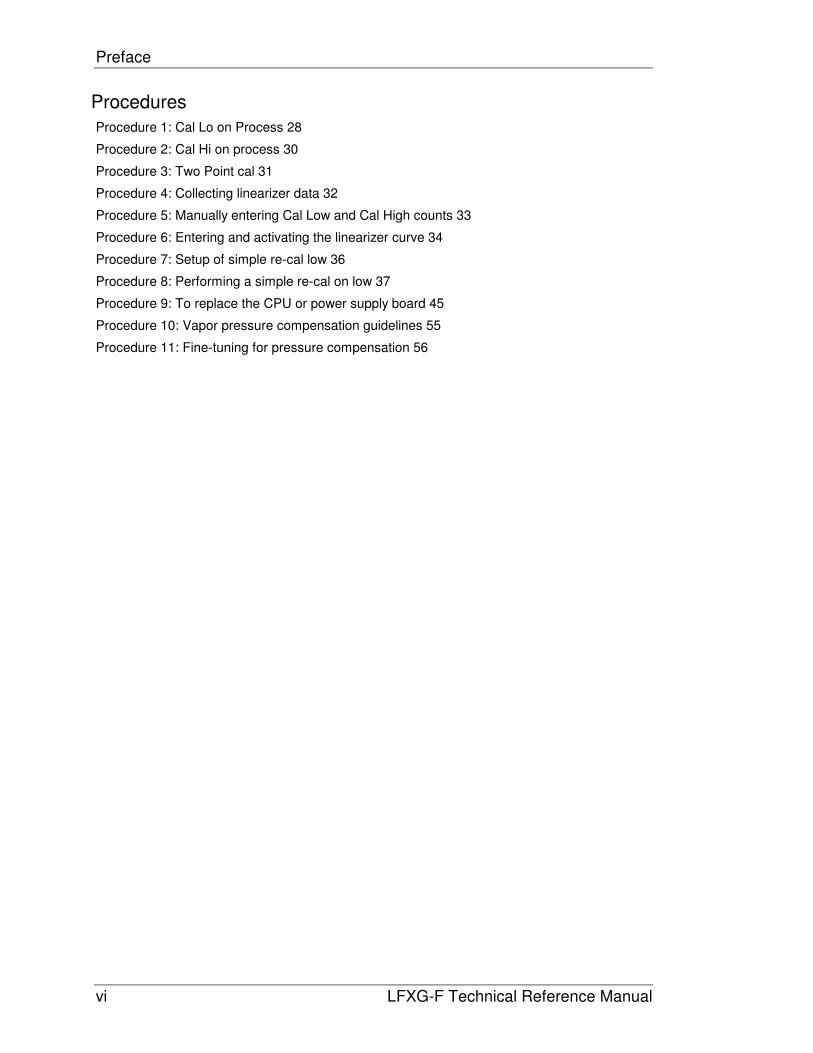
Procedures
Procedure 1: Cal Lo on Process 28
Procedure 2: Cal Hi on process 30
Procedure 3: Two Point cal 31
Procedure 4: Collecting linearizer data 32
Procedure 5: Manually entering Cal Low and Cal High counts 33
Procedure 6: Entering and activating the linearizer curve 34
Procedure 7: Setup of simple re-cal low 36
Procedure 8: Performing a simple re-cal on low 37
Procedure 9: To replace the CPU or power supply board 45
Procedure 10: Vapor pressure compensation guidelines 55
Procedure 11: Fine-tuning for pressure compensation 56

Preface
LFXG-F Technical Reference Manual vii
Explanation of symbols
Table 2 lists the symbols that the manual and instrument use.
Table 2: Explanation of symbols
Radiation notice
In the manual, information concerning radioactive materials
or radiation safety information is found in the accompanying
text.
Caution
In the manual, warnings concerning potential damage to the
equipment or bodily harm are found in the accompanying
text.
AC current or voltage
On the instrument, a terminal to which or from which an
alternating (sine wave) current or voltage may be applied or
supplied.
DC current or voltage
On the instrument, a terminal to which or from which a
direct current voltage may be applied or supplied.
Potentially hazardous voltages
On the instrument, a terminal on which potentially
hazardous voltage exists.

Preface
viii LFXG-F Technical Reference Manual
Your comments
VEGA values your opinion! Please fill out this page so that we can continually improve our
technical documentation.
Manual: LFXG-F Technical Reference Manual
Date: ______________
Customer Order Number: ___________________
How we can contact you (optional if you prefer to remain anonymous):
Name: _________________________
Title: _________________________
Company: __________________________
Address: __________________________
__________________________
__________________________
Did you find errors in this manual? If so, specify the error and page number.
Did you find this manual understandable, usable, and well organized? Please make
suggestions for improvement.
Was information you needed or would find helpful not in this manual? Please specify.
Please send this page to:
VEGA Americas, Inc.
Director of Engineering
4241 Allendorf Drive
Cincinnati, OH 45209-1599
Preface
LFXG-F Technical Reference Manual ix
Notes

LFXG-F Technical Reference Manual 1
Chapter 1: Introduction
Nuclear materials notice
This equipment contains radioactive source material that emits gamma radiation. Gamma
radiation is a form of high-energy electromagnetic radiation. Only persons with a specific
license from the U.S. NRC (or other regulating body) may perform the following to the source
holder:
• Dismantle
• Install
• Maintain
• Relocate
• Repair
• Test
VEGA Field Service engineers have the specific license to install and commission nuclear
gauges, and can instruct you in the safe operation of your density gauge. To contact VEGA
Field Service, call 513-272-0131. Users outside the U.S. and Canada may contact their local
representative for parts and service.
Note: Special instructions concerning your source holder are found in
the envelope that was shipped with the source holder and the
“Radiation Safety for U.S. General and Specific Licensees, Canada,
and International Users” manual and “Radiation Safety References
Addendum” CD. Please refer to this document for radiation safety
information.
Introduction
2 LFXG-F Technical Reference Manual
Unpacking the equipment
CAUTION!
Make sure that you are familiar with radiation safety practices in
accordance with your U.S. Agreement State, U.S. NRC, or your
country’s applicable regulations before unpacking the equipment.
� Unpack the unit in a clean, dry area
� Inspect the shipment for completeness, by checking against the packing slip
� Inspect the shipment for damage during shipment or storage
� If the detector is included as a separate package in the shipment, inspect the assembly for damage that may have occurred during shipment or storage
� If there was damage to the unit during shipment, file a claim against the carrier, reporting the damage in detail. Any claim on the VEGA for shortages, errors in shipment, etc., must be made within 30 days of receipt of the shipment
� If you need to return the equipment, see the section “Returning equipment for repair to VEGA” in the “Diagnostics and Repair” chapter
� After you unpack the equipment, inspect each source holder in the shipment to assure that the operating handle is in the OFF position. In the event that you find the handle in the ON position, place it in the OFF position immediately and secure it.
Note: Most source holder models accept a lock. Call VEGA Field
Service immediately for further instructions, at 513-272-0131, if the
source holder has one of the following conditions:
• Does accept a lock and there is no lock on it
• The lock is not secured
• You are unable to secure the lock
• The operating handle does not properly move into the off position
Introduction
LFXG-F Technical Reference Manual 3
Storing the equipment
Storing the source holder
If it is necessary to store the source holder, do so in a clean, dry area. Be sure the source
holder shutter is in the OFF or CLOSED position. Check the current local regulations (U.S.
NRC, Agreement State, or other) to determine if this area must have any restrictions.
Storing the detector
Avoid storage at temperatures below freezing. Store the detector indoors in an area that has
temperature-control between 10 °C and 35 °C (50 °F and 95 °F) and less than 50% relative
humidity. Store equipment in dry conditions until installation.
Certifications
This gauge is designed for certi�cation compliance from the following agencies:
• ATEX Standard
• CCOE (India)
• CEPEL/INMETRO (Brazil)
• CSA
• FM Standard
• GOST-B Standard
• GOST-R Standard
• IECex
• JIS (Japan)
• KTL (Korea)
• NEPSI (China)
Introduction
4 LFXG-F Technical Reference Manual
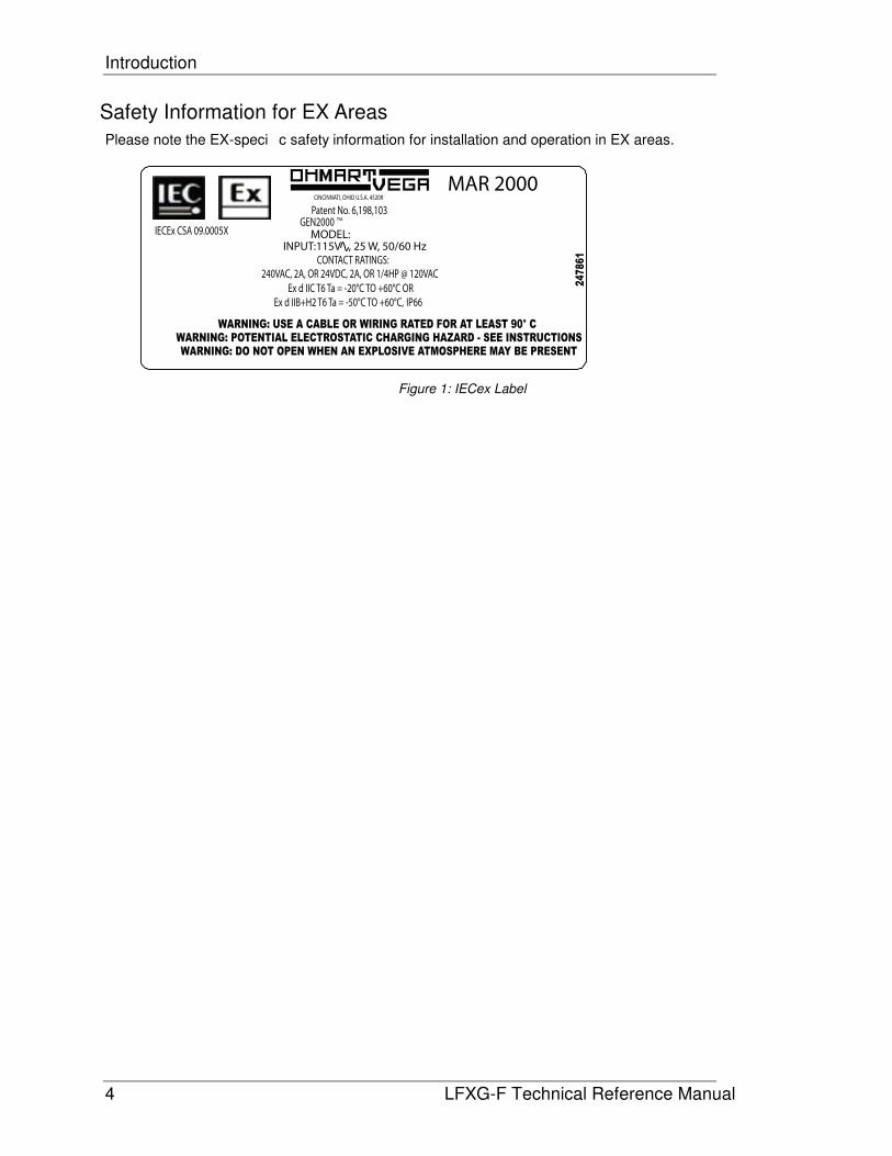
MAR 2000
MODEL: GEN2000
TM
CONTACT RATINGS:
240VAC, 2A, OR 24VDC, 2A, OR 1/4HP @ 120VAC
Ex d IIC T6 Ta = -20°C TO +60°C OR
Patent No. 6,198,103
IP66Ex d IIB+H2 T6 Ta = -50°C TO +60°C,
IECEx CSA 09.0005X
CINCINNATI, OHIO U.S.A. 45209
INPUT:115V , 25 W, 50/60 Hz
WARNING: USE A CABLE OR WIRING RATED FOR AT LEAST 90° C
WARNING: POTENTIAL ELECTROSTATIC CHARGING HAZARD - SEE INSTRUCTIONS
WARNING: DO NOT OPEN WHEN AN EXPLOSIVE ATMOSPHERE MAY BE PRESENT
24
78
61
Safety Information for EX Areas
Please note the EX-speci�c safety information for installation and operation in EX areas.
Figure 1: IECex Label
Introduction
LFXG-F Technical Reference Manual 5
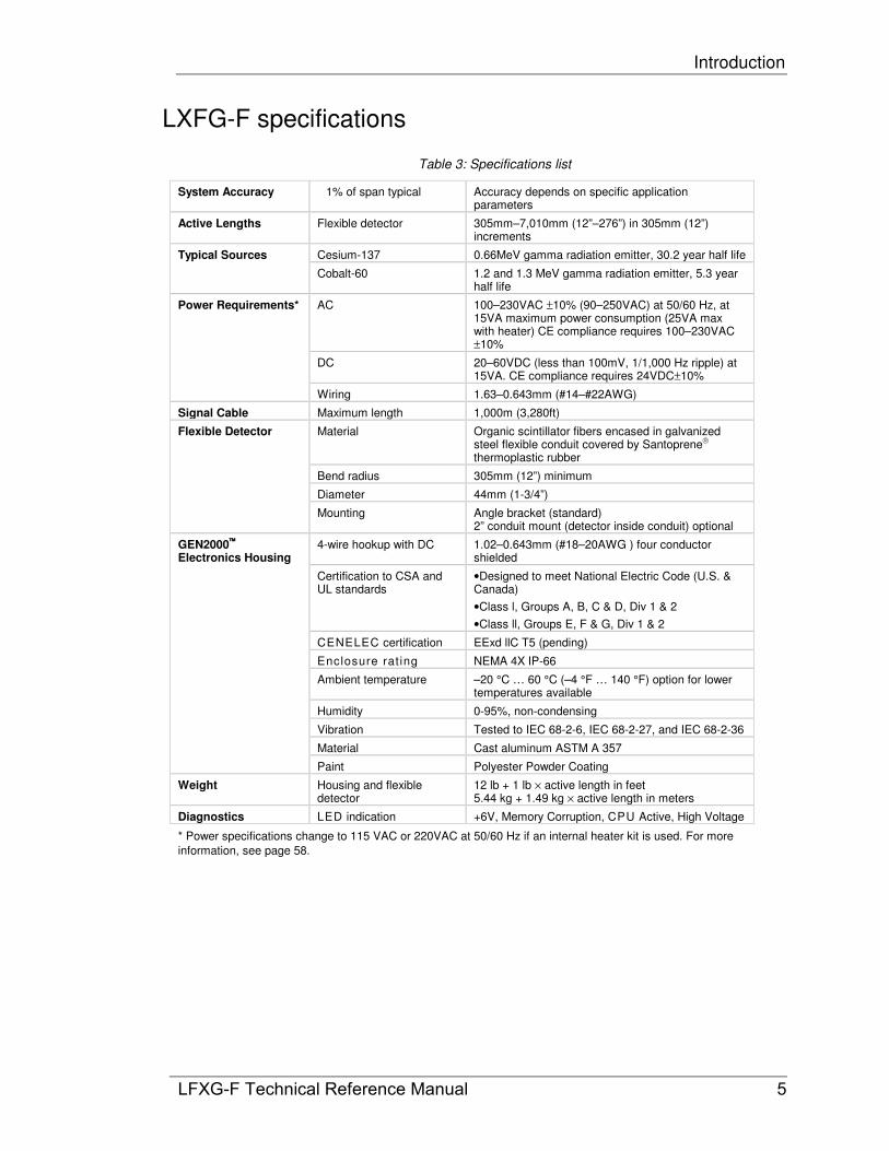
LXFG-F specifications
Table 3: Specifications list
System Accuracy �1% of span typical Accuracy depends on specific application parameters
Active Lengths Flexible detector 305mm–7,010mm (12”–276”) in 305mm (12”) increments
Typical Sources Cesium-137 0.66MeV gamma radiation emitter, 30.2 year half life
Cobalt-60 1.2 and 1.3 MeV gamma radiation emitter, 5.3 year half life
Power Requirements* AC 100–230VAC ±10% (90–250VAC) at 50/60 Hz, at 15VA maximum power consumption (25VA max with heater) CE compliance requires 100–230VAC ±10%
DC 20–60VDC (less than 100mV, 1/1,000 Hz ripple) at 15VA. CE compliance requires 24VDC±10%
Wiring 1.63–0.643mm (#14–#22AWG)
Signal Cable Maximum length 1,000m (3,280ft)
Flexible Detector Material Organic scintillator fibers encased in galvanized steel flexible conduit covered by Santoprene thermoplastic rubber
Bend radius 305mm (12”) minimum
Diameter 44mm (1-3/4”)
Mounting Angle bracket (standard) 2” conduit mount (detector inside conduit) optional
GEN2000 Electronics Housing
4-wire hookup with DC 1.02–0.643mm (#18–20AWG ) four conductor shielded
Certification to CSA and UL standards
•Designed to meet National Electric Code (U.S. & Canada)
•Class l, Groups A, B, C & D, Div 1 & 2
•Class ll, Groups E, F & G, Div 1 & 2
CENELEC certification EExd llC T5 (pending)
Enclosure rat ing NEMA 4X IP-66
Ambient temperature –20 °C … 60 °C (–4 °F … 140 °F) option for lower temperatures available
Humidity 0-95%, non-condensing
Vibration Tested to IEC 68-2-6, IEC 68-2-27, and IEC 68-2-36
Material Cast aluminum ASTM A 357
Paint Polyester Powder Coating
Weight Housing and flexible detector
12 lb + 1 lb × active length in feet 5.44 kg + 1.49 kg × active length in meters
Diagnostics LED indication +6V, Memory Corruption, CPU Active, High Voltage
* Power specifications change to 115 VAC or 220VAC at 50/60 Hz if an internal heater kit is used. For more
information, see page 58.
Introduction
6 LFXG-F Technical Reference Manual
Typical applications
VEGA level gauges accurately indicate the level of liquids or bulk materials throughout a range
on vessels, reactors, or tanks.
In order to achieve a level indication over the desired length, it may be necessary to use more
than one detector. The manner in which these multiple detectors link together depends upon
the types of detectors used. Specific details on using multiple detectors are available in
“Appendix I: Special Applications”.
A level gauge may be used in a number of applications such as the following:
Pulp and Paper
• Liquors
• Bleach plant chemicals
• Coating chemical storage
• Lime mud
• Wastewater treatment tanks
Chemical
• Low pressure/low vapor chemical storage
• Settlers
• Surge tanks
Food and beverage
• Food slurries
• Pastes
• Syrups
• Dough level
• Intermediate batch storage
Water / wastewater
• Settling/aeration tanks
• Clarifiers
• Sludge holding tanks
• Wet wells

Introduction
LFXG-F Technical Reference Manual 7
Where to find help
If you need help finding information, check the Index and Table of Contents within this manual.
In addition, the gauge has “Help” screens that you can view using the universal hand-held
terminal or VEGA View™ software. These help screens are useful references for definitions of
parameters and hints.
VEGA Customer Service
VEGA Customer Service has Field Service Engineers located across the U.S. for on-site
service to U.S. and Canada. In many cases, a Field Service Engineer is at your plant for the
start up of your gauge. In addition, Field Service Engineers regularly assist customers over the
phone.
If you have a question or need help, call Customer Service during office hours. If your problem
is an emergency (for example, line shut down because of VEGA equipment), you can reach us
24-hours a day.
Table 4: Contact information
Contact InformationContact InformationContact InformationContact Information Telephone NumberTelephone NumberTelephone NumberTelephone Number
Monday through Friday 8:00 A.M. - 5:00 P.M. EST (Eastern Standard Time)
1-513-272-0131
Emergencies: Follow the voice mail instructions
1-513-272-0131
Fax 1-513-272-0133
In addition, VEGA provides field service for customers outside the U.S. and Canada.
Customers outside the U.S. and Canada can also contact their local VEGA representative for
parts and service.
When calling with a question, if possible, please have the following information ready:
� VEGA Customer Order (C.O.) Number—Locate on the engraved label on the source holder
� Sensor serial number—Locate on the sensor housing inside the external housing
Introduction
8 LFXG-F Technical Reference Manual
Principle of operation
VEGA's nuclear level gauges direct a narrow beam of radiation through the vessel to a
radiation detector. The beam is collimated (shaped) so that the entire active length of the
detector is exposed to a radiation field.
The material in the vessel blocks the radiation in proportion to its level, the higher level, the
more radiation is blocked and the less is sensed by the detector. The material in the vessel
essentially acts as a shield, preventing a portion of the detector from being exposed to the
radiation field. The gauge is calibrated to associate the detector readings called counts with
the level of the material in the desired engineering units. The output of the detector is a 0/100
kHz true digital frequency output, in proportion to the level of the process.
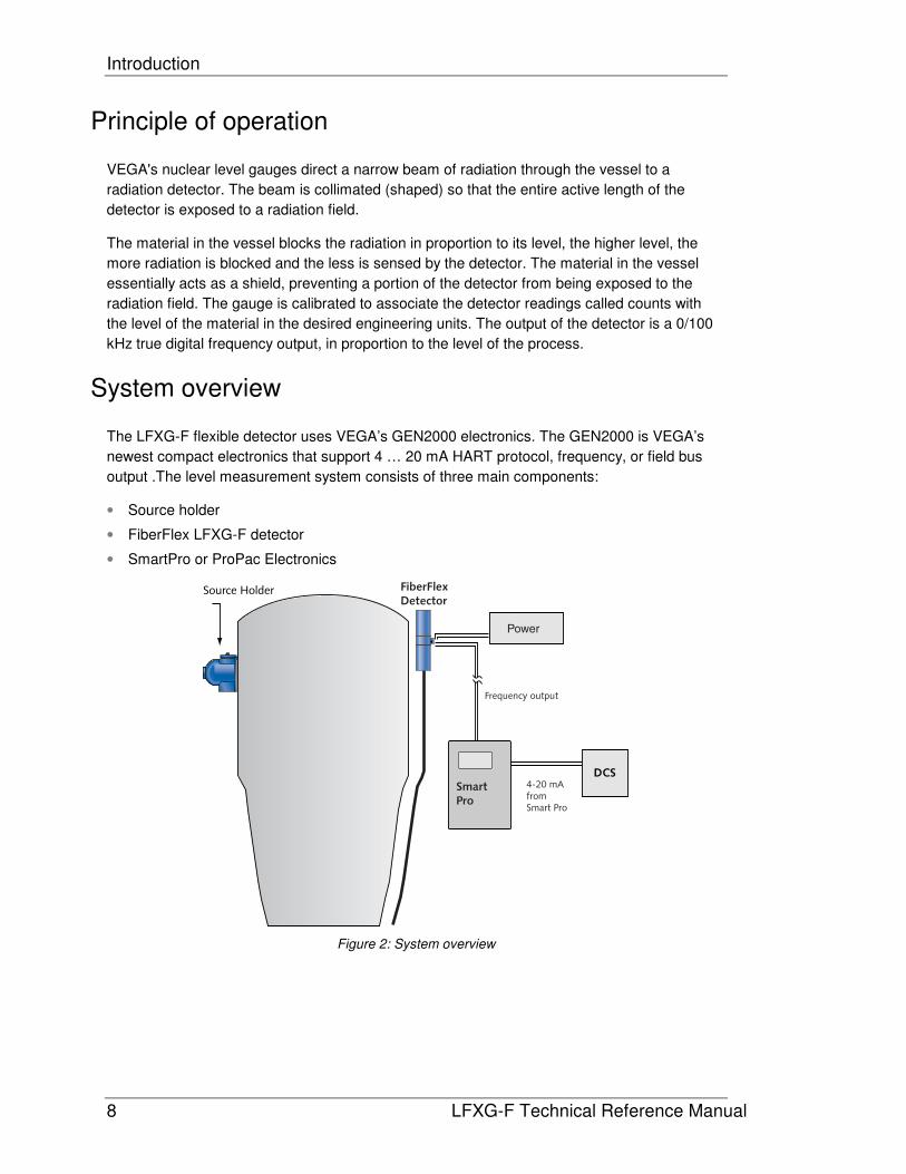
System overview
The LFXG-F flexible detector uses VEGA’s GEN2000 electronics. The GEN2000 is VEGA’s
newest compact electronics that support 4 … 20 mA HART protocol, frequency, or field bus
output .The level measurement system consists of three main components:
• Source holder
• FiberFlex LFXG-F detector
• SmartPro or ProPac Electronics
Figure 2: System overview
Introduction
LFXG-F Technical Reference Manual 9
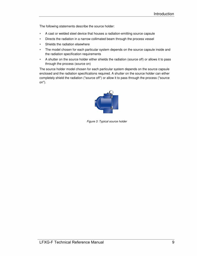
The following statements describe the source holder:
• A cast or welded steel device that houses a radiation-emitting source capsule
• Directs the radiation in a narrow collimated beam through the process vessel
• Shields the radiation elsewhere
• The model chosen for each particular system depends on the source capsule inside and
the radiation specification requirements
• A shutter on the source holder either shields the radiation (source off) or allows it to pass
through the process (source on)
The source holder model chosen for each particular system depends on the source capsule
enclosed and the radiation specifications required. A shutter on the source holder can either
completely shield the radiation ("source off") or allow it to pass through the process ("source
on").
Figure 3: Typical source holder
Introduction
10 LFXG-F Technical Reference Manual
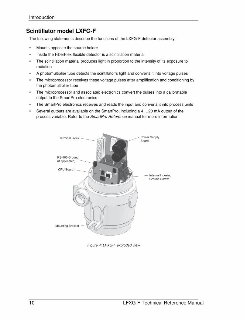
Scintillator model LXFG-F
The following statements describe the functions of the LXFG-F detector assembly:
• Mounts opposite the source holder
• Inside the FiberFlex flexible detector is a scintillation material
• The scintillation material produces light in proportion to the intensity of its exposure to
radiation
• A photomultiplier tube detects the scintillator’s light and converts it into voltage pulses
• The microprocessor receives these voltage pulses after amplification and conditioning by
the photomultiplier tube
• The microprocessor and associated electronics convert the pulses into a calibratable
output to the SmartPro electronics
• The SmartPro electronics receives and reads the input and converts it into process units
• Several outputs are available on the SmartPro, including a 4 …20 mA output of the
process variable. Refer to the SmartPro Reference manual for more information.
Terminal Block
RS-485 Ground
(if applicable)
CPU Board
Mounting Bracket
Internal Housing
Ground Screw
Power Supply
Board
Figure 4: LFXG-F exploded view

Introduction
LFXG-F Technical Reference Manual 11
Communicating with the gauge
Use either a SmartPro or ProPac to enable the following:
• Initial setup
• Calibration
• Operation


LFXG-F Technical Reference Manual 13
Chapter 2: Installation
Location considerations
At the time you ordered the level transmitter, VEGA sized the source for optimal performance.
Notify VEGA prior to installation of the gauge if the location of the gauge is different from the
original order location. Proper location of the level gauge can sometimes mean the difference
between satisfactory and unsatisfactory operation.
Note: Try to locate the source holder in such a place that process
material will not coat it. This ensures the continuing proper operation of
the source ON/OFF mechanism. Many regulatory agencies (for
example, the U.S. NRC) require periodic testing of the ON/OFF
mechanism. Refer to the “Radiation Safety for U.S. General and
Specific Licensees, Canada, and International Users” manual and
“Radiation Safety References Addendum” CD that came with the
source holder and the appropriate current regulations for details.
Stable temperature
Mount the level gauge on a portion of the line where the temperature of the process material is
relatively stable. Process temperature can effect the gauge indication. The amount of the
effect depends upon the following:
• Sensitivity of the gauge
• Temperature coefficient of the process material
Protect insulation
If insulation is between the measuring assembly and the process, protect the insulation from
liquids. The absorption of a liquid, such as water, can affect the gauge indication because it
blocks some radiation.
Avoid internal obstructions
The best possible installation of a nuclear level gauge is on a vessel that has no internal
obstructions (agitator, baffle, man ways, and so forth) directly in the path of the radiation beam.
If one of these obstructions is present, it can shield the radiation from the detector, causing an
erroneous reading. If the vessel has a central agitator, the source holder and detector can
mount to the vessel on an arc other than a diameter, so that the beam of radiation does not
cross the agitator. You can also avoid other obstructions this way.
Installation
14 LFXG-F Technical Reference Manual
Avoid external obstructions
Any material in the path of the radiation can affect the measurement. Some materials that are
present when the gauge initially calibrates pose no problem because the calibration accounts
for their effect. Examples of these materials are:
• Tank walls
• Liners
• Insulation
However, when the materials change or you introduce new ones, the gauge reading can be
erroneous.
Examples of these situations are:
• Insulation that you add after calibration absorbs the radiation and causes the gauge to
erroneously read upscale.
• Rapidly changing tank conditions due to material buildup. Regular standardizations
compensate for slowly changing tank conditions due to material buildup. See the
“Calibration” chapter for information on standardization.
Avoid source cross-talk
When multiple adjacent pipes or vessels have nuclear gauges, you must consider the
orientation of the source beams so that each detector senses radiation only from its
appropriate source. The best orientation, in this case, is for the source holders to be on the
inside with radiation beams pointing away from each other.

Installation
LFXG-F Technical Reference Manual 15
Mounting the measuring assembly
Note: The handle on the source holder operates a rotating shutter.
When installing or removing the assembly from the pipe, you must turn
the handle to the closed or Off position and lock the handle with the
combination lock that VEGA provides.
There are two types of mounting options. The first type is the bracket mount. The L bracket
supports the electronics housing. For this type of mounting, the conduit clamps should be
spaced every 24”.
The second type of mounting is the conduit mount. This type of mount consists of an adapter
with a 2” conduit coupler. It provides an air hose fitting for applications that need to cool the
detector. The conduit mount requires a user-supplied nipple and conduit adapter (union).
Shown below are the two mounting types.
Figure 5: Conduit and bracket mounting
Note: The active area (where it is possible to make a level measurement) is between the
bottom of the housing and the end of the flexible conduit. Mount the detector so that this area
spans the desired measurement length.
Conduit mounting Bracket mounting

Installation
16 LFXG-F Technical Reference Manual
Wiring the equipment
VEGA provides detailed Interconnect drawings for the LSGF.
Note: If the instructions on the drawing differ from the instructions in this manual, use the
drawing. It may contain special instructions specific to your order.
Use the drawing notes and the steps that follow to make the input and output connections.
Make the connections at the removable terminal strips mounted on the CPU board. Access the
CPU board by removing the explosion-proof housing cap.
Note: Not all connections are required for operation. See Table 5 for terminal names and
positions.
VEGA provides an internal and external ground screw for connection of the power Earth
ground wire. After removing the top cover, the location of the internal ground screw is at the
front of the housing. The location of the external ground screw is next to the conduit entry.
Terminal Block
RS-485 Ground
(if applicable)
CPU Board
Mounting Bracket
Internal Housing
Ground Screw
Power Supply
Board
Figure 6: External and internal housing ground

Installation
LFXG-F Technical Reference Manual 17
Figure 7: Interconnect diagram
Figure 8: Interconnect connections
Output signal cable
Measure signalBLK
WHT
Auxiliary frequency
input
PowerEarth ground
Power InPower In
+ Freq
- Freq
+ Aux
- Aux
Internal
housing ground
Power cable perlocal codes.
External
housing ground
1 2 3 4 5 6 7 8 9 10 11 12 13 14
AC
L1 o
r D
C
AC
L2 o
r D
C
Fre
quency o
ut
Fre
quency o
ut
Auxili
ary
in –
Auxili
ary
in +
Installation
18 LFXG-F Technical Reference Manual
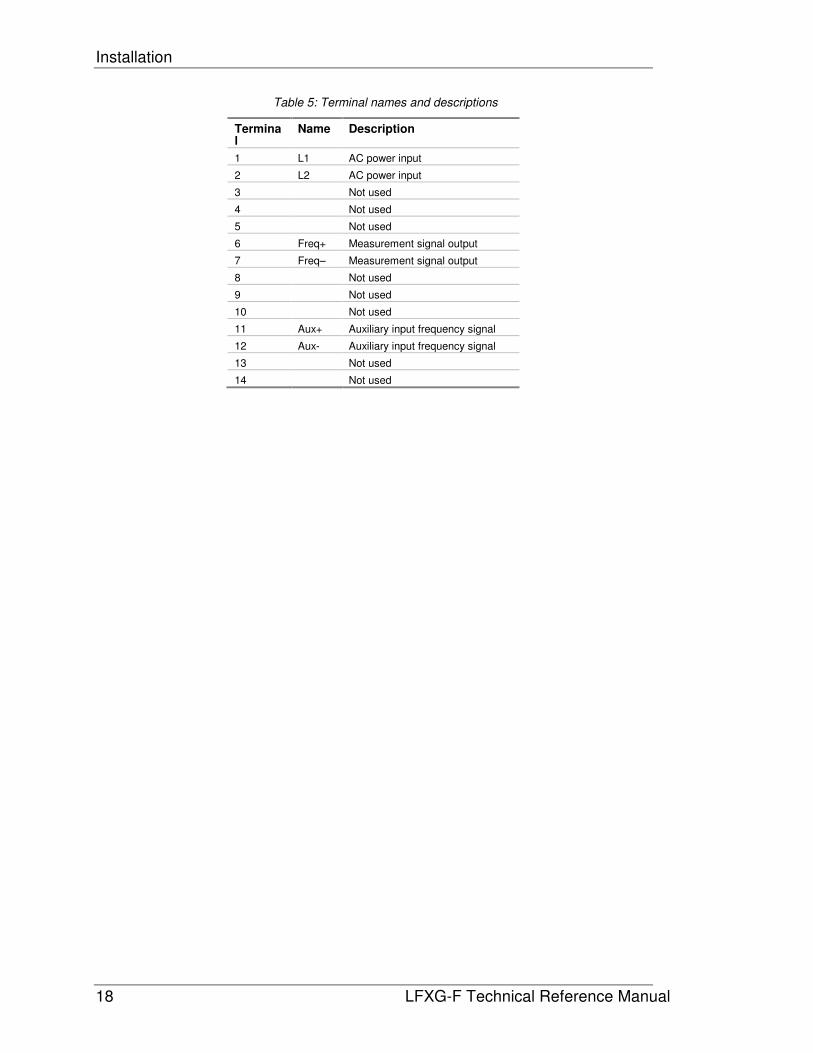
Table 5: Terminal names and descriptions
Terminal
Name Description
1 L1 AC power input
2 L2 AC power input
3 Not used
4 Not used
5 Not used
6 Freq+ Measurement signal output
7 Freq– Measurement signal output
8 Not used
9 Not used
10 Not used
11 Aux+ Auxiliary input frequency signal
12 Aux- Auxiliary input frequency signal
13 Not used
14 Not used
Installation
LFXG-F Technical Reference Manual 19
Power
CAUTION!
DO NOT APPLY POWER until a thorough check of all the wiring is
complete!
The AC power source voltage input is 100–234VAC±10% (90–250VAC) at 50/60 Hz, at 15VA
maximum power consumption. AC power must not be shared with transient producing loads.
The DC power source voltage input is 20–60VDC (24VDC±10% for CE compliance)(less than
100 mV, 1/1,000 Hz ripple) at 15VA maximum power consumption. DC power cable can be
part of a single cable 4-wire hookup, or can be separate from output signal cable. (See "Output
current loop " section)
Use wire between #14–#22AWG (1.63 to 0.643mm) for power wiring.
Switch for CE compliance
For CE compliance, install a power line switch no more than one meter from the operator
control station.
SmartPro and ProPac connections
The measurement signal from pins 6 and 7 go to an VEGA SmartPro or ProPac. The
measurement signal is 0/100 kHz, maximum, true digital, and satisfies RS-422 and RS-423.
See the table below for interconnect information.
Table 6: LSGF interconnect to SmartPro or ProPac
From LSGF To SmartPro To ProPac
Pin 6 TB 4-1 TB 1-4
Pin 7 TB 4-2 TB 1-5
Shield wire TB 4-3 TB 1-12
Conduit
Conduit runs must be continuous and you must provide protection to prevent conduit moisture
condensation from dripping into any of the housings or junction boxes. Use sealant in the
conduit, or arrange the runs so that they are below the entries to the housings and use weep
holes where permitted.
You must use a conduit seal-off in the proximity of the housing when the location is in a
hazardous area. Requirements for the actual distance must be in accordance with local code.
If you use only one conduit hub, plug the other conduit hub to prevent the entry of dirt and
moisture.
Installation
20 LFXG-F Technical Reference Manual
Commissioning the gauge
The process of commissioning the gauge includes the following:
• Taking appropriate radiation field tests
• Checking the pre-programmed setup parameters
• Calibrating on process
• Verifying the working of the gauge.
VEGA Field Service Engineers typically commission the gauge. It is necessary to remove the
source holder lock the first time the gauge takes measurements in the field. Only persons with
a specific license from the U.S. NRC, Agreement State, or other appropriate nuclear regulatory
body may remove the source holder lock.
Note: Users outside the U.S. must comply with the appropriate nuclear
regulatory body regulations in matters pertaining to licensing and
handling the equipment.

Installation
LFXG-F Technical Reference Manual 21
Can you remove the source holder lock?
If you are in doubt whether you have permission to remove the source holder lock…Do not!
The license sets limits on what the user can do with the gauge. Licenses fall into two
categories:
1. General
2. Specific
It is up to the user to review the license to determine if they have the appropriate permission to
perform any of the following:
• Disassemble
• Install
• Relocate
• Repair
• Test
• Unlock
You can remove the source lock if installation of the gauge is in the U.S. and you have the
specific license to remove the source holder lock. Confirm that your license specifically states
that you have the permission to perform this operation and then contact VEGA Field Service
Radiation Safety for the combination.
Do not remove the lock if the gauge has a general license tag, installation is in the U.S., and
you do not have the specific license that gives you permission to remove the lock. You can
verify whether the gauge is a general license gauge by checking the source holder for the
general license tag. If it is not there, it is not a general license device.
If you do not have permission to remove the source holder lock, an VEGA Field Service
Engineer or another person with this specific license must remove it for you.
Installation
22 LFXG-F Technical Reference Manual
Field service commissioning call checklist
In many U.S. installations, an VEGA Field Service Engineer commissions the gauge. To
reduce service time and costs, use this checklist to ensure the gauge is ready for commission
before the Field Service Engineer arrives:
� Mount the source holder and detector per the certified drawings found in the custom information folder in this manual, allowing access for future maintenance
� Make all wiring connections per the certified drawings and the “Wiring the Equipment” section in this manual. Tie in the wiring from the field transmitter analog output to the DCS/PLC/chart recorder
� Ensure that the AC power to the transmitter is a regulated transient-free power source. UPS type power is the best
� If using DC power, verify that the ripple is less than 100mV
Note: The equipment warranty is void if there is damage to the gauge due to incorrect wiring
not checked by the VEGA Field Service Engineer.
� Have process ready for calibration
� Mount the source holder and detector per the certified drawings found in the custom
information folder in this manual.
� Allow access for future maintenance.
� Make all wiring connections per the certified drawings and the "Wiring the equipment"
section in this manual. Tie in the wiring from the SmartPro analog output to the
DCS/PLC/chart recorder.
Ensure that the AC power to the detector and SmartPro is a regulated transient-free power
source. UPS type power is the best.
� Have process ready for calibration. When possible, it is best to be able to completely fill
and empty the vessel, at the high and low levels for the initial calibration procedure, and
when possible at 10% increments in between for the linearization procedure.
� Do not remove the lock on the source holder. Notify VEGA Field Service if the lock has
been damaged or if the lock is missing.
LFXG-F Technical Reference Manual 23
Chapter 3: Calibration
Note: This chapter discusses calibration with a SmartPro or ProPac. If your FiberFlex LFXG-F
is used to output to a HART® level transmitter, refer to the HART
® level manual for calibration
instructions.
Use the SmartPro or ProPac (the software in both operates identically) to calibrate the LFXG-
F. Refer to the SmartPro Reference for instructions to use the SmartPro software. To perform
the calibration, you must be familiar with the SmartPro topics:
• Navigating through the SmartPro screens
• Security access level
• Product Code
• Saving to EEPROM
• Accessing 520-level screens and changing item values
This section provides a summary of the calibration procedure for a standard level. Refer to the
SmartPro Reference and the SmartPro Mini Guide to Fast Startups for more details.
SmartPro Note: The instructions in this manual are compatible with SmartPro firmware
vx04.00 or later.

Calibration
24 LFXG-F Technical Reference Manual
Memory backup
To set the EEPROM in write-protect mode, remove the jumper from pins (JP17) on the
SmartPro or ProPac CPU board. The CPU saves in three different memory areas. These
areas are:
• Lower RAM (active)—battery maintained
• Upper RAM (with battery-backup)—copy of lower RAM for backup
• EEPROM (non-volatile)—copy of lower RAM for redundant backup
Lower RAM is the memory that the gauge uses during operation.
The upper RAM and EEPROM data do not download unless the operator explicitly commands
it to do so. The operator performs this procedure if trying to recover from a memory corruption.
310 MEMORY BACKUP
UPPER RAM TRANSFERS
EEPROM TRANSFERS

Calibration
LFXG-F Technical Reference Manual 25
Calibration with SmartPro
Calibration establishes reference points that relate the detector output to actual (or known)
values of the process.
You must make an initial calibration before the gauge can make measurements of any
accuracy. Perform the initial calibration after the installation and commission of the gauge at
the actual field site.
Before using the LFXG-F to make measurements, you must perform the following:
• Calibrate it to relate the detection of radiation from the source to the density of the process
material
• Periodically, you must re-cal the system on process to adjust for changes over time
You do not need to repeat the initial calibration as long as certain critical process and
equipment conditions remain the same. See "When a new initial calibration may be necessary"
on page 35.
Choosing the calibration method
For each installation, the user must choose one of two ways to calibrate the level detector. The
best calibration method depends on how the continuous level detector is to be used. Read the
following table to decide which method to use.
Table 7: Choosing a calibration method
Calibration with a linearizer curve Calibration with no linearizer curve
Use a linearizer curve if…the gauge is required to be repeatable and accurately indicate the level of process throughout the span.
Don’t use a linearizer curve if…the gauge is only required to be repeatable, but need not accurately indicate the level of process.
Typically used for vessels in which it is critical to know the accurate level.
Typically used for surge bins or other vessels under control, in which one level is to be maintained.
The linearizer curve must be turned on, after collection of linearizer data and entering the curve in the SmartPro (Screen 528 item 41 set to 1)
The linearizer curve must be turned off (Screen 528 item 41 set to 0)
Note: If you do not use a linearizer curve, the measurement indication will be repeatable but
not accurate between the Cal Low Level and Cal High Level points. The measurement
indication will not be linear with respect to the actual process level. In some applications,
accuracy is not critical and this method can be used.
If your application requires a linear or accurate indication of the actual process level, you must
use a linearizer curve.
Calibration
26 LFXG-F Technical Reference Manual
Two-point calibration
The calibration of a LFXG-F is a "two-point" calibration, with known level process samples near
both the high and low end of the span read by the LFXG-F gauge. Use the SmartPro or
ProPac electronics to perform the calibration.
SmartPro Note: Refer to the SmartPro Mini Guide to Fast Startups for systematic calibration
instructions. In addition, Chapter 3 of the SmartPro Reference provides detailed information on
the calibration process. Be sure to follow the instructions for a level gauge as indicated on the
flow chart in the beginning of the SmartPro Mini Guide to Fast Startups.
The span setting, data collection of high and low samples, and calculation of the two-point
calibration establish the "endpoints" of the calibration curve (level vs. raw counts on a graph).
The calibration curve is non-linear, due to the measurement method of radiation transmission.
The linearizer determines the shape of the curve between the endpoints.
Note: When performing calibration or any other procedure that affects the output of the gauge,
be sure to disable the gauge from your distributed control system’s (DCS) automatic control.
Set process span
The SmartPro (or ProPac) calculates the process span based on the lowest (Min Reading) and
the highest level (Max Reading) that you want the LFXG-F to measure. Enter the low and high
levels in the SmartPro SETUP MENU 2 OF 4 under the SET GAGE SPAN screen.
The measurement span was set at VEGA's factory, based on information received at the time
of the order. If you move the LFXG-F from its intended location, or are measuring on a
different span, you must modify the span setting. In any case, it is a good practice to verify that
the setting is correct.
Calibration
LFXG-F Technical Reference Manual 27
Cal Lo on Process
Setting the low level for calibration requires measurement with the level gauge of the empty
vessel or lowest level. This sets the low end (sometimes referred to in the U.S. as zero) of the
calibration curve.
Perform this procedure either before or after setting the high level, but after entering the
process span correctly in the SET GAGE SPAN screen, from the SETUP MENU 2 OF 4.
Before starting the cal low data collection:
� Empty the vessel
� Enter the password for Supervisor-level access on screen 052
� Verify on screen 502 that the SmartPro is receiving the frequency input from the level
detector, usually above 9000 counts for an empty vessel
Note: You must perform data collection for the low and high level within ten days of each other
for a good calibration. The low and high values must be more than 10% of the process span
apart for the most accurate calibration.
Increasing the process span usually increases the gauge accuracy.
Calibration
28 LFXG-F Technical Reference Manual
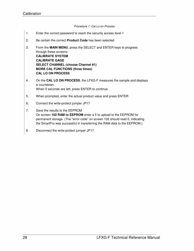
Procedure 1: Cal Lo on Process
1. Enter the correct password to reach the security access level 1
2. Be certain the correct Product Code has been selected
3. From the MAIN MENU, press the SELECT and ENTER keys to progress
through these screens:
CALIBRATE SYSTEM
CALIBRATE GAGE
SELECT CHANNEL (choose Channel #1)
MORE CAL FUNCTIONS (three times)
CAL LO ON PROCESS
4. On the CAL LO ON PROCESS, the LFXG-F measures the sample and displays
a countdown
When 0 seconds are left, press ENTER to continue
5. When prompted, enter the actual product value and press ENTER
6. Connect the write-protect jumper JP17
7. Save the results to the EEPROM
On screen 102 RAM to EEPROM enter a 1 to upload to the EEPROM for
permanent storage. (The “error code” on screen 102 should read 0, indicating
the SmartPro was successful in transferring the RAM data to the EEPROM.)
8. Disconnect the write-protect jumper JP17.
Calibration
LFXG-F Technical Reference Manual 29
Cal Hi on Process
Cal Hi on Process sets the “gain” of the calibration curve. Setting the high level for calibration
can be simulated by shutting the source holder shutter. In some cases, simulating the high
level may not be accurate, but you can adjust for it later when the tank is full. (See Procedure
5: Manually entering Cal Low and Cal High counts)
Before starting the cal high data collection:
� Turn the source holder shutter to the Off position
� Enter the password for Supervisor-level access on screen 052
� Verify on screen 502 that the SmartPro is receiving the frequency input from the level
detector. With a closed shutter, the counts should be close to zero.
Perform this procedure either before or after setting the low level, but after entering the
process span correctly in the SET GAGE SPAN screen, from the SETUP MENU 2 OF 4.
Note: Perform data collection for the low and high density within ten days of each other for a
good calibration. The low and high values must be more than 10% of the process span apart
for the most accurate calibration.
Increasing the process span usually increases the gauge accuracy.

Calibration
30 LFXG-F Technical Reference Manual
Procedure 2: Cal Hi on process
1. Enter the correct password to reach the security access level 1
2. Verify that the correct Product Code has been selected
3. From the main menu, use the SELECT and ENTER keys to progress through
these screens:
CALIBRATE SYSTEM
CALIBRATE GAGE
SELECT CHANNEL (choose Channel #1)
MORE CAL FUNCTIONS (1 time)
CAL HI ON PROCESS
4. On the CAL HI ON PROCESS screen, the LFXG-F measures the sample and
displays a countdown
When 0 seconds are left, press ENTER to continue
5. At the prompt, enter the actual product value and press ENTER
6. Connect the write-protect jumper JP17
7. Save the results to the EEPROM
On screen 102 RAM to EEPROM enter a 1 to upload to the EEPROM for
permanent storage. (The “error code” on screen 102 should read 0, indicating
the SmartPro was successful in transferring the RAM data to the EEPROM.)
8. Disconnect the write-protect jumper JP17.
Calibration
LFXG-F Technical Reference Manual 31
Calculate calibration with Two Point Cal
After collecting the high and low-level calibration data, the SmartPro can make the calibration
gain calculation.
Note: If you do not need a linearizer curve for the installation, the calibration is complete. You
need not follow the next steps to create a linearizer curve.
Procedure 3: Two Point cal
1. From the CHANNEL #1 menu, move through:
MORE CAL FUNCTIONS
TWO POINT CAL
2. From the TWO POINT CAL prompt, select YES
The SmartPro uses the Cal Lo and Cal Hi data points to calculate the calibration
3. Connect the write-protect jumper JP17
4. Save the results to the EEPROM
On screen 102 RAM to EEPROM enter a 1 to upload to the EEPROM for
permanent storage. (The “error code” on screen 102 should read 0, indicating
the SmartPro was successful in transferring the RAM data to the EEPROM.)
5. Disconnect the write-protect jumper JP17.

Calibration
32 LFXG-F Technical Reference Manual
Creating a linearizer curve (optional)
To decide if you need to create a linearizer curve for the installation, check the guidelines on
page 25, “Choosing the initial calibration method.”
To create a linearizer curve, you must take measurements with the gauge at intermediate
levels between empty and full. You will record the sensor counts at each level, and call VEGA
with the data. VEGA will calculate a linearizer curve and provide you with the data to enter into
the SmartPro.
Typical fill points are 25%, 50%, and 75%. The more points measured, the more accurate the
linearization curve will be.
Procedure 4: Collecting linearizer data
1. Fill the vessel to 25% or your first fill level. Be sure you know the level as
accurately as possible.
2. Access screen 168 Data Collect on the SmartPro.
Press ENTER to begin the data collection. A countdown timer will begin
3. When the countdown reaches zero, screen 168 will display the average counts
for the data collection.
Record the average counts and the actual level in a table. (See below.)
4. Repeat the procedure for each fill level, including full, or 100%
Table 8: Linearizer data
Nominal level Actual level Average counts
25%
50%
75%
100%
Note: You may find that the counts for a full vessel are more than the counts using a closed
shutter to simulate a full vessel. This means the shutter blocks more of the radiation than the
process does. Alternatively, when the vessel is full, some radiation beams over the process.
If this is the case, you can manually enter the counts for a full vessel in the SmartPro memory
and have it re-calculate the gain with the “Two point calibrate” function. See the procedure
below.
You must know how to access the 520-level screens and change items.

Calibration
LFXG-F Technical Reference Manual 33
Manually entering Cal High and Cal Low counts (optional)
Procedure 5: Manually entering Cal Low and Cal High counts
1. Access screen 520
2. At item 40, enter the counts that represent 100%.
3. If you need to change the empty counts, enter them at item 39
4. Access screen 152 Cal Channel #1 and select Two Point Calibrate
5. On screen 155, select YES to indicate you have done a cal low and cal high.
6. Connect the write-protect jumper JP17
7. On screen 157, select YES to store the calibrate result in the EEPROM
This causes the SmartPro to calculate a new gain, based on the values you
manually entered
8. Disconnect the write-protect jumper JP17.
Calibration
34 LFXG-F Technical Reference Manual
Entering and activating the linearizer curve
Finally, the linearizer curve must be calculated and entered into the SmartPro.
Procedure 6: Entering and activating the linearizer curve
1. Call VEGA Field Service (513-272-0131) or FAX (513-272-4381) with the counts
you obtained for the fill levels and recorded on the chart. Be sure to provide
VEGA a FAX number or e-mail address where you can receive linearizer curve
data points
2. VEGA will use special software to calculate a linearizer curve from your data.
They will FAX you 41 data point values for your linearizer curve, which you must
enter into the SmartPro
3. Enter the 41 values on the SmartPro screen 528, items 0 through 40. (Item 0 will
always have a value of 0, and item 40 will always have a value of 10,000.)
4. Make the curve active by entering a value 1 at screen 528 item 41. At screen
528, use the Auto/Man button and Yes/No button to increment and decrement
the item number (If a 0 is entered at item 41, the SmartPro will not use the curve
you just entered.)
5. Connect the write-protect jumper JP17
6. Save the results to the EEPROM
On screen 102 RAM to EEPROM enter a 1 to upload to the EEPROM for
permanent storage. (The “error code” on screen 102 should read 0, indicating
the SmartPro was successful in transferring the RAM data to the EEPROM.)
7. Disconnect the write-protect jumper JP17.

Calibration
LFXG-F Technical Reference Manual 35
When a two-point initial calibration is impossible
In some installations, it is impossible to attain the high and low level conditions required for a
two-point calibration. Calibration of the system is still possible with expert assistance. In this
case, contact VEGA Field Service for advice at (513)272-0131.
When a new calibration may be necessary
Under most circumstances, you do not need to repeat the calibration procedure. The system
requires only periodic re-cal to compensate for drifts over time. However, certain events can
necessitate a new initial calibration. These events are as follows:
• Measurement of a new process application (contact VEGA for recommendation)
• Requirement of a new measurement span by the process
• Entry of a new measurement span setting in the software
• Installation of a new radiation source holder
• Moving the level gauge to another location (in U.S. only specifically licensed persons may
relocate the gauge)
• Any change in the process vessel, for example lining, insulation, agitator
• Build up or erosion of vessel is excessive and cannot be compensated for with a re-cal
Calibration
36 LFXG-F Technical Reference Manual
Periodic re-cal
Re-cal adjusts the system by resetting one point of the calibration curve to an independently
measured or known level. This is typically performed on an empty vessel.
The frequency of re-cal depends on several factors, including the desired accuracy of the
reading.
SmartPro Note: The “Simple re-cal low” method is presented in this manual, because that is
typically used for continuous level gauges.
Refer to the SmartPro Reference Chapter 3, section ”Re-Cal / Channel #1 (Category II
Functions)” for more information about choosing a method and performing the periodic re-cal.
Setup of the Simple Re-Cal Low establishes in the SmartPro the default value of the level to
use for re-cals.
Procedure 7: Setup of simple re-cal low
1. Know the value of the level (in engineering units) you use for re-calibration, for
example, 0%, 0 inches, 10 cm. You must use this level each time you perform a
Simple Re-Cal Low
2. From the Main Menu 1 of 2, press the SELECT and ENTER keys to progress
through these screens:
Calibrate System
Calibrate Gage
Select Channel (choose Channel #1)
More Cal Functions (3 times)
Enter Absorber Value
Low Absorber Value
3. Connect the write-protect jumper JP17
4. On the LOW ABSORBER screen 147, enter the new value of the low level
condition and press ENTER
The screen prompts “Save?” Select YES to save the new value
5. The SmartPro automatically saves the results to the EEPROM. When finished, it
displays “Attempt completed”
Select DONE to finish.
6. Disconnect the write-protect jumper JP17
Calibration
LFXG-F Technical Reference Manual 37
Procedure 8: Performing a simple re-cal on low
1. Be certain the correct Product Code has been selected
2. From the Main Menu, use the SELECT and ENTER keys to progress through
these screens:
Calibrate System
Calibrate Gage
Select Channel (choose Channel #1)
Simple Re-cal Low
3. On the CAL START/STOP screen, press ENTER to “Start data collect”
The gauge measures the sample and the SmartPro displays “Collecting Data”
4. Connect the write-protect jumper JP17
5. On screen 145, the SmartPro displays the counts for the data collect. It prompts
“Save results?”
Select YES to save the re-cal results
6. The SmartPro automatically saves the results to the EEPROM. When finished, it
displays “Attempt completed”
Select DONE to finish.
7. Disconnect the write-protect jumper JP17

Calibration
38 LFXG-F Technical Reference Manual
Notes
LFXG-F Technical Reference Manual 39
Chapter 4: Diagnostics and repair
Software diagnostics
Refer to the SmartPro manual for software diagnostics information.
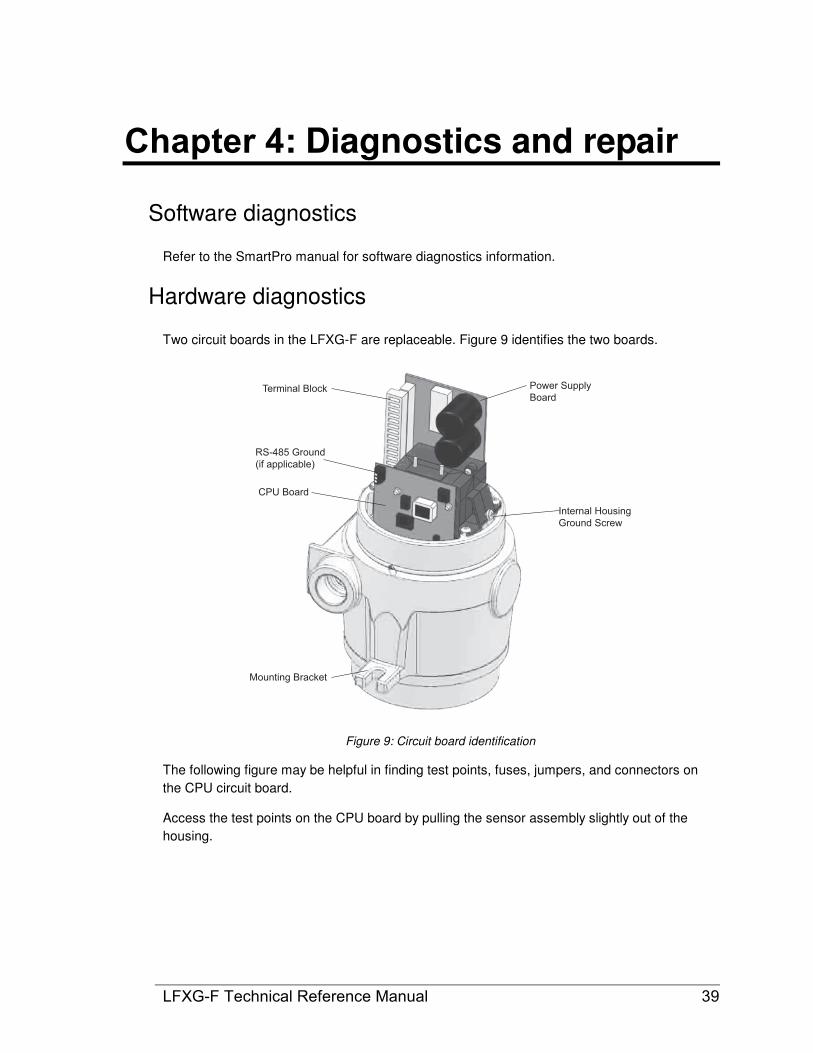
Hardware diagnostics
Two circuit boards in the LFXG-F are replaceable. Figure 9 identifies the two boards.
Terminal Block
RS-485 Ground
(if applicable)
CPU Board
Mounting Bracket
Internal Housing
Ground Screw
Power Supply
Board
Figure 9: Circuit board identification
The following figure may be helpful in finding test points, fuses, jumpers, and connectors on
the CPU circuit board.
Access the test points on the CPU board by pulling the sensor assembly slightly out of the
housing.
Diagnostics and repair
40 LFXG-F Technical Reference Manual
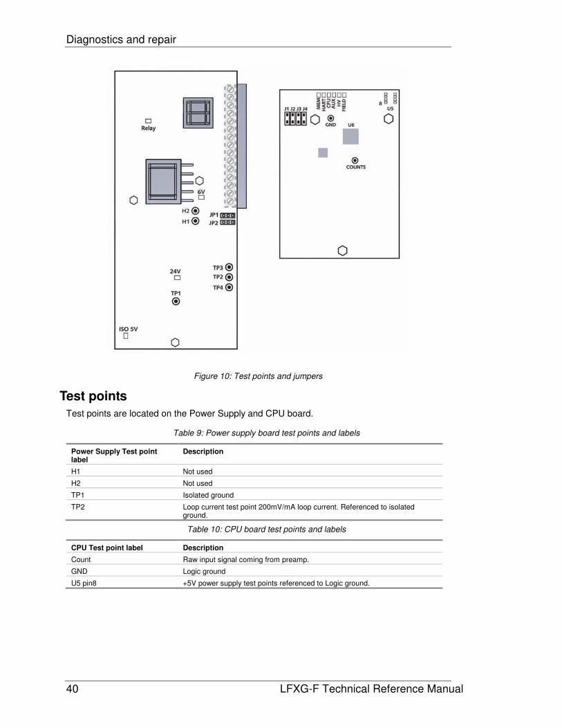
Figure 10: Test points and jumpers
Test points
Test points are located on the Power Supply and CPU board.
Table 9: Power supply board test points and labels
Power Supply Test point label
Description
H1 Not used
H2 Not used
TP1 Isolated ground
TP2 Loop current test point 200mV/mA loop current. Referenced to isolated ground.
Table 10: CPU board test points and labels
CPU Test point label Description
Count Raw input signal coming from preamp.
GND Logic ground
U5 pin8 +5V power supply test points referenced to Logic ground.

Diagnostics and repair
LFXG-F Technical Reference Manual 41
Jumpers
The LFXG-F uses jumpers J1–J4 on the CPU board as division values for the output
frequency to the SmartPro.
Note: Do not change the jumper from the current setting without consulting VEGA Field
Service
Table 11: Jumper division values
J1 Divide by 20
J2 Divide by 10
J3 Divide by 5
J4 Divide by 2
None Divide by 1
If the LFXG-F does not have a jumper, the division value is one.
LED indicators
Check the basic functioning of the VEGA electronics at the instrument with LED indicators on
the CPU board. They are visible when you remove the explosion proof housing cap.
See the tables on page 41 for a summary of the LED indications.
FIE
LD
ME
M
HA
RT
CP
U
AU
X
HV
FIE
LD
HV
AU
X
CP
U
HA
RT
ME
M
On
Blinking
Off
Normal LED pattern Memory corrupt pattern
Figure 11: LED indicators
Power Supply Board LED summary table Table 12: Power Supply Board LED summary table
LED Description Normal condition Error condition Recommendation
+6V +6V DC voltage level to electronics
ON OFF Electronics are not receiving +6V DC voltage required for functioning
Verify +6V on test points. Check fuse on Power Supply board. Check power input terminals 1, 2.
+24V Not used
Relay Not used
Diagnostics and repair
42 LFXG-F Technical Reference Manual
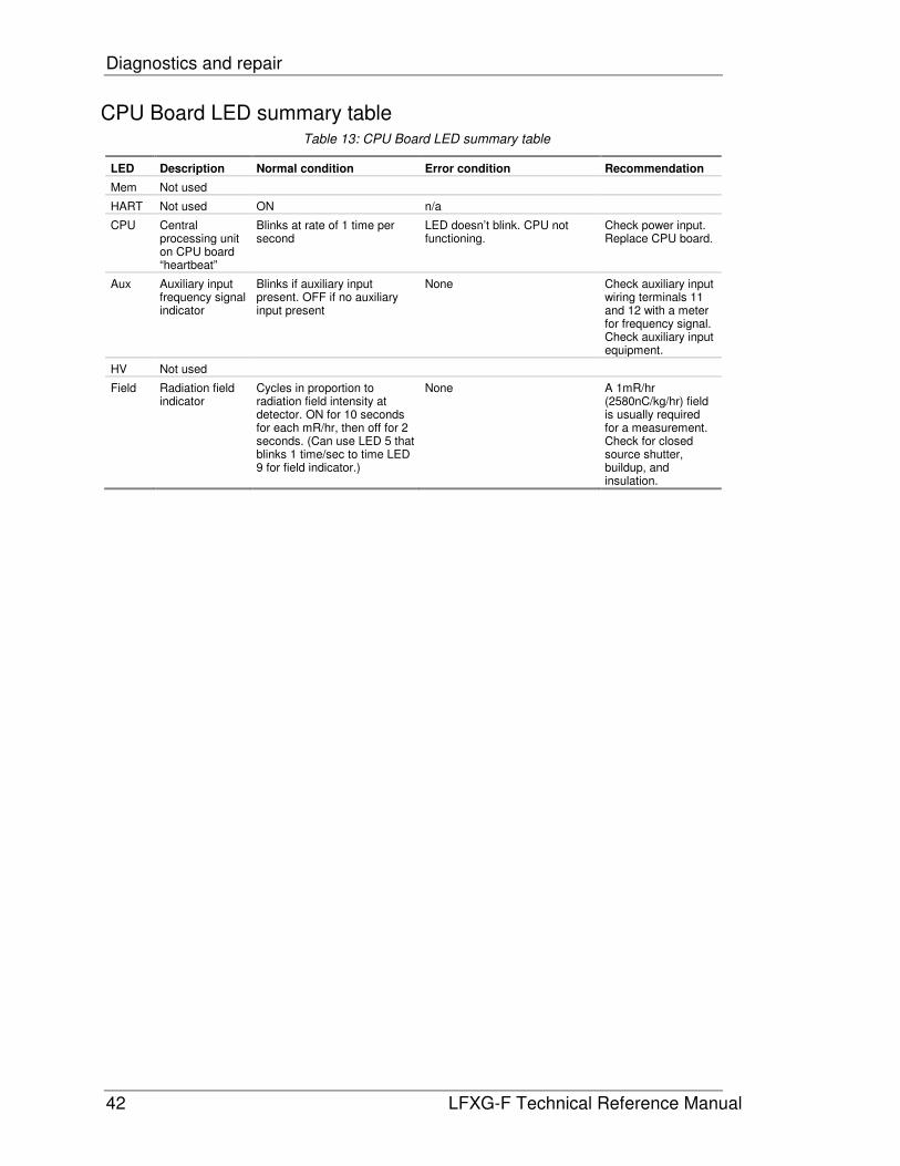
CPU Board LED summary table Table 13: CPU Board LED summary table
LED Description Normal condition Error condition Recommendation
Mem Not used
HART Not used ON n/a
CPU Central processing unit on CPU board “heartbeat”
Blinks at rate of 1 time per second
LED doesn’t blink. CPU not functioning.
Check power input. Replace CPU board.
Aux Auxiliary input frequency signal indicator
Blinks if auxiliary input present. OFF if no auxiliary input present
None Check auxiliary input wiring terminals 11 and 12 with a meter for frequency signal. Check auxiliary input equipment.
HV Not used
Field Radiation field indicator
Cycles in proportion to radiation field intensity at detector. ON for 10 seconds for each mR/hr, then off for 2 seconds. (Can use LED 5 that blinks 1 time/sec to time LED 9 for field indicator.)
None A 1mR/hr (2580nC/kg/hr) field is usually required for a measurement. Check for closed source shutter, buildup, and insulation.
Diagnostics and repair
LFXG-F Technical Reference Manual 43
Maintenance and repair
Periodic maintenance schedule
Since the VEGA LFXG-F contains no moving parts, very little periodic maintenance is required.
We suggest the following schedule to prevent problems and to comply with radiation
regulations:
Table 14: Maintenance schedule
Description Frequency Procedure
Re-cal As required by process conditions, usually at least once a month
Calibration chapter
Source holder shutter check
Every six months unless otherwise required by applicable nuclear regulatory agency
Radiation safety instructions (shipped separately with source holder and in the folder of this manual)
Source wipe Every three years unless otherwise required by applicable nuclear regulatory agency
Radiation safety instructions (shipped separately with source holder and in the folder of this manual)
Spare parts
Contact VEGA Field Service at +1 513-272-0131 for parts, service, and repairs.
Outside the U.S., contact your local VEGA representative for parts, service, and repairs.

Diagnostics and repair
44 LFXG-F Technical Reference Manual
Field repair procedures
Very few parts are field repairable, but you can replace entire assemblies or boards. The
following parts are replaceable:
• CPU circuit board
• Power supply circuit board
Use great care to prevent damage to the electrical components of the gauge. VEGA
recommends appropriate electrostatic discharge procedures.
CAUTION!
NEVER remove the two screws holding down the sensor electronics. This contains the
photomultiplier tube assembly. This component is easily damaged. Removing the sensor and
then re-installing it can cause sensor problems.
NEVER remove the bottom cover. This protects the coupling joint of the flexible scintillator.
There are no serviceable parts under the bottom cover.

Diagnostics and repair
LFXG-F Technical Reference Manual 45
Replacing the CPU or power supply board
You may have to replace a circuit board if there is damage to one of its components. Before
replacing a circuit board, check the troubleshooting flowcharts or call VEGA Field Service to be
sure a replacement is necessary.
The sensor EEPROM contains a backup of the CPU board EEPROM. After physically
replacing the CPU board, you must perform a memory backup to update the CPU board
EEPROM with the information in the sensor board EEPROM. Perform the memory back up in
the New hardware screen, from the Advanced Fxns menu.
Procedure 9: To replace the CPU or power supply board
1. Turn off power to the gauge
2. Remove the housing cover
3. Remove the plastic electronics cover
4. Remove the terminal wiring connector
5. Remove the three (3) screws holding the electronics package in place
6. Carefully pull the electronics package out of the housing.
7. Remove the appropriate board from the clamshell assembly by removing the three
(3) mounting nuts.
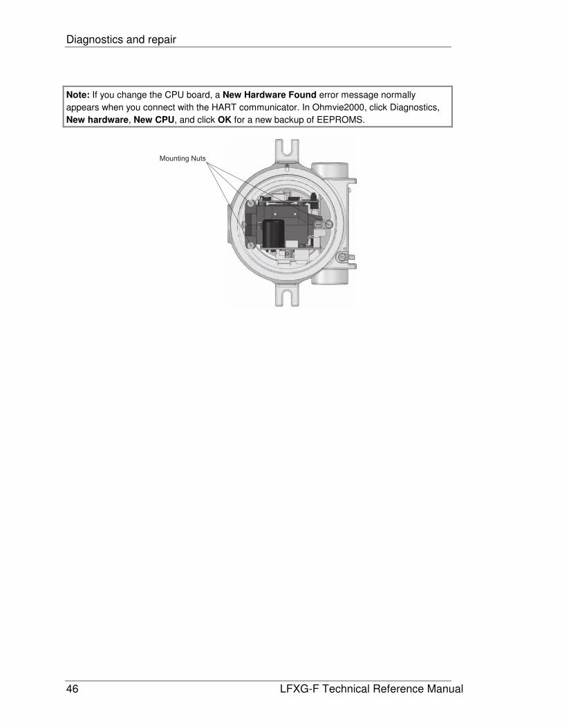
Note: If you are changing the CPU board, you must move the old firmware chip to
the new board if the new board firmware is different.
8. Carefully reconnect any ribbon cables.
9. Install the electronics package in the housing.
10. Replace the three (3) mounting nuts.
11. Reconnect the terminal wiring connector.
12. Install the plastic electronics cover.
13. Install the housing cover.
14. Turn on the power to the unit.
Diagnostics and repair
46 LFXG-F Technical Reference Manual
Note: If you change the CPU board, a New Hardware Found error message normally
appears when you connect with the HART communicator. In Ohmvie2000, click Diagnostics,
New hardware, New CPU, and click OK for a new backup of EEPROMS.
Mounting Nuts

Diagnostics and repair
LFXG-F Technical Reference Manual 47
Requesting field service
To request field service within the U.S. and Canada; call 513-272-0131 from 8:00 A.M. to
5:00 P.M. Monday through Friday. For emergency service after hours, call 513-272-0131 and
follow the voice mail instructions.
Returning equipment for repair to VEGA
When calling VEGA to arrange repair service, be ready with the following information:
� Product model that is being returned for repair
� Description of the problem
� VEGA Customer Order (C.O.) Number
� Purchase order number for the repair service
� Shipping address
� Billing address
� Date needed
� Method of shipment
� Tax information


LFXG-F Technical Reference Manual 49
Appendix I: Special applications
This chapter provides application specific information for special installations.
If your application is not in this chapter, you may find application specific information on the
certified drawings. If you have other application questions, contact VEGA Field Service in the
U.S. or Canada at 513-272-0131 or your local rep outside of the U.S. or Canada.

Appendix I: Special applications
50 LFXG-F Technical Reference Manual
Multiple detectors summation
Some applications require a measurement length longer than the maximum level detector
length.
Figure 12: Multiple detectors summation
SmartPro
Summed frequency
output to SmartPro
Frequency output to
last level detector
FiberFlex with
frequency output
LFXG-F
FiberFlex with
frequency output LFXG-F

Appendix I: Special applications
LFXG-F Technical Reference Manual 51
Special drawings from VEGA
Identification of applications that require multiple detectors occurs at the time of order. The end
user, engineering contractor (or both) receive certified drawings for the exact equipment
ordered. Refer to the drawings along with this section of the manual.
Note: If the instructions on the drawings and this manual differ, follow the drawing instructions.
They will be specific to your order.
Installation requirements
A multiple detector application consists of at least one detector that is capable of summing an
input frequency (e.g., model FiberFlex LFXG-F, or an LSF, LJF, or LNF). Follow these
installation guidelines:
• Install the summing detector at the top of the measurement range
• Offset the detectors vertically so that the end of the top detector’s active length
corresponds to the beginning of the bottom detector’s active length
• Place all detectors in the radiation beam.
Figure 13: Placement of multiple detectors

Appendix I: Special applications
52 LFXG-F Technical Reference Manual
Detector wiring
Multiple-detector applications require at least two frequency output detectors electrically linked
in a chain. Only the last detector in the chain sends an output to the SmartPro. The LFXG-F
automatically sums the frequency input (auxiliary input, pins 11/12) with the frequency it
generates in response to radiation. The summed frequency is output at pins 6/7. When no
input is present at pins 11/12, the output is only the detector’s response to the radiation.
Jumpers to reduce counts
The SmartPro cannot accept more than 32,767 counts per second. If the total counts exceeds
this, a jumper can be set on the last detector in the chain to divide the output to the SmartPro.
This must be set before calibrating. Verify the frequency is fewer than 32,767 with a meter at
the SmartPro input terminal on empty vessel condition. If the frequency exceeds 32,767, adjust
the jumper on the last detector as required, according to the table, below.
Table 15: Multiple detector jumper adjustments
J1 Divides counts by 20
J2 Divides counts by 10
J3 Divides counts by 5
J4 Divides counts by 2
No jumpers Divides counts by 1
Initial settings and calibration requirements
No special SmartPro software initial settings or calibration methods are required. The
detectors automatically sum the frequencies, so the use of multiple detectors is transparent to
the SmartPro.
Use the levels for the entire measurement span as if it were one long detector when you set
the span and calibrate the gauge.

Appendix I: Special applications
LFXG-F Technical Reference Manual 53
Vapor pressure compensation
A nuclear level gauge works on the principle that the product shields the detector from the
radiation beam, allowing more or less radiation to strike the detector as the product level falls
and rises. For an accurate level indication, the variation in the detector output should depend
only on the product level.
However, vapor pressure variations in the headspace of the vessel can cause erroneous
product level indications. This is because the vapor also blocks some of the radiation. When
the pressure is higher, more radiation is blocked; when the vapor pressure is lower, less is
blocked. Therefore, even at the same product level, the detector can receive varying amounts
of radiation, depending on the head vapor pressure.
You can compensate with a density measurement of the vapor space using an VEGA nuclear
density gauge. It monitors the vapor space density, and sends its frequency output to the
SmartPro channel 2. Input the level measurement is to the SmartPro channel 1, as usual.
Special firmware enables the elimination of the vapor density effect in the final level indication.
Figure 14: Vapor compensation system

Appendix I: Special applications
54 LFXG-F Technical Reference Manual
Installation requirements
Mount the level detector as usual. You must mount the density gauge so that it is in the
radiation beam, but is above the highest expected level. This ensures that the only process
condition affecting the density gauge is the gaseous pressure change in the vessel.
The pressure compensation algorithm in special SmartPro firmware makes use of the change
in vapor pressure to determine the amount of compensation needed to correct the level
indication.

Appendix I: Special applications
LFXG-F Technical Reference Manual 55
Detector wiring
Wire the level detector frequency output into the SmartPro TB4, pins 1 and 2. Wire the density
gauge output into SmartPro TB4, pins 5 and6.
Initial settings and calibration requirements
Note: Setting up a pressure-compensated level gauge system involves many application-
specific considerations. VEGA Field Service should be on-site to set up the system.
To set up a system with vapor pressure compensation, follow these general guidelines with the
assistance of VEGA Field Service:
Procedure 10: Vapor pressure compensation guidelines
1. At the VEGA factory, the density gauge output channel will be set up to point to
the temperature compensated raw counts location
2. Set up and calibrate the level gauge as usual. See the Calibration chapter of this
manual for instructions
3. After the level gauge is calibrated, establish a known, minimum pressure in the
vessel
4. At the SmartPro, access screen 521, item 14. This displays the counts from the
density detector when the pressure is at a minimum. Make note of the counts
5. Access screen 529, item 109. Copy the counts value from the above step to
item 109. This sets up the reference counts of the density detector
6. Access screen 529, item 110. Enter an initial gain term value at this address.
Initially, enter the value 1800 (which is a gain of 1.8). You may need to adjust
this value later to fine tune the system
7. Access screen 529, item 120. Enter a value of 1 at this address to enable the
pressure compensation feature. (A value of 0 disables the pressure
compensation.)
Pressure compensation is now set up, but you must fine-tune it for it to work properly.
Appendix I: Special applications
56 LFXG-F Technical Reference Manual
Pressure compensation fine tuning
Since variables such as the vessel geometry, process material characteristics, and pressure
change ranges affect the output, it is difficult to accurately predict the gain term needed for an
individual installation. Fine-tuning the system requires maintaining a known level of process
material, and changing the gaseous vapor pressure. By observing how the system reacts, you
can adjust the gain term value on SmartPro screen 529, item 110. Follow the general
guidelines below:
Procedure 11: Fine-tuning for pressure compensation
1. In the vessel, establish a known, repeatable minimum pressure
2. Establish a process level of approximately 30% to 60%. Make note of the initial
level indication, as displayed on the SmartPro operator screen
3. Increase and maintain pressure to some value near the maximum pressure
likely to be present inside the vessel. Do not adjust the process level in the
vessel
4. Allow time for the level measurement to stabilize
5. Compare the level measurement at maximum pressure to the measurement at
minimum pressure
• If the level indication at maximum pressure is less than at minimum
pressure, then the gain term is too large. Reduce the gain term (screen 529,
item 110) in increments of 100 until the level indication is the same as it was
at minimum pressure. With each change to the gain term, be sure to allow
time for the level measurement to stabilize
• If the level indication at maximum pressure is greater than at minimum
pressure, then the gain term is too small. Increase the gain term (screen
529, item 110) in increments of 100 until the level indication is the same as it
was at minimum pressure. With each change to the gain term, be sure to
allow time for the level measurement to stabilize
6. Connect the write-protect jumper JP17
7. When the gain term is set at a satisfactory value, do an upload to the EEPROM
to save the settings permanently
8. Disconnect the write-protect jumper JP17
9. If you need to disable the pressure compensation, access screen 529, item 120.
Enter a value of 0 at this address. (A value of 1 enables the pressure
compensation.)
Appendix I: Special applications
LFXG-F Technical Reference Manual 57
SmartPro memory locations for pressure compensation
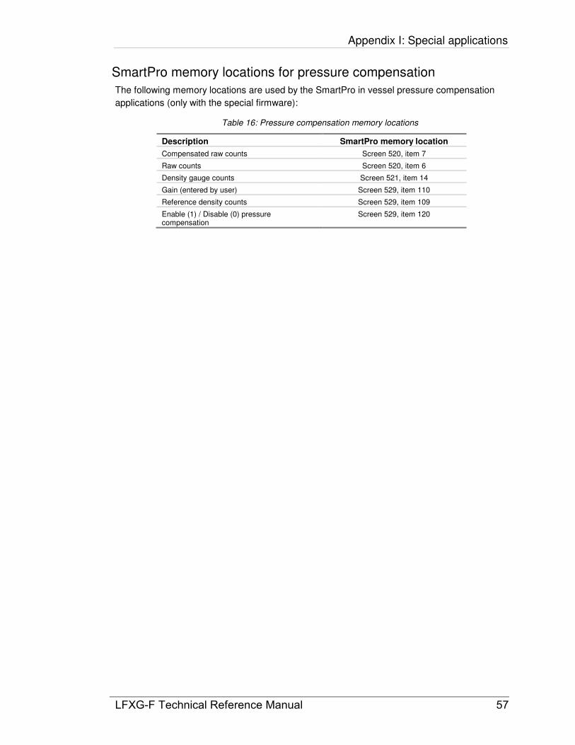
The following memory locations are used by the SmartPro in vessel pressure compensation
applications (only with the special firmware):
Table 16: Pressure compensation memory locations
Description SmartPro memory location
Compensated raw counts Screen 520, item 7
Raw counts Screen 520, item 6
Density gauge counts Screen 521, item 14
Gain (entered by user) Screen 529, item 110
Reference density counts Screen 529, item 109
Enable (1) / Disable (0) pressure compensation
Screen 529, item 120
Appendix I: Special applications
58 LFXG-F Technical Reference Manual
Internal heater kit for applications as lows as –50 °°°°C
A heater kit option is available for the LFXG-F for applications that require a –50 °C (–58 °F)
temperature rating. With the heater option, the internal temperature of the unit rises
approximately +30 °C (+54 °F) degrees.
The features of the heater are as follows:
• The heater kit does not affect the functionality of the LFXG-F in any way. There is no
requirement for special firmware
• The factory installs the internal heater kit if you order it with the LFXG-F
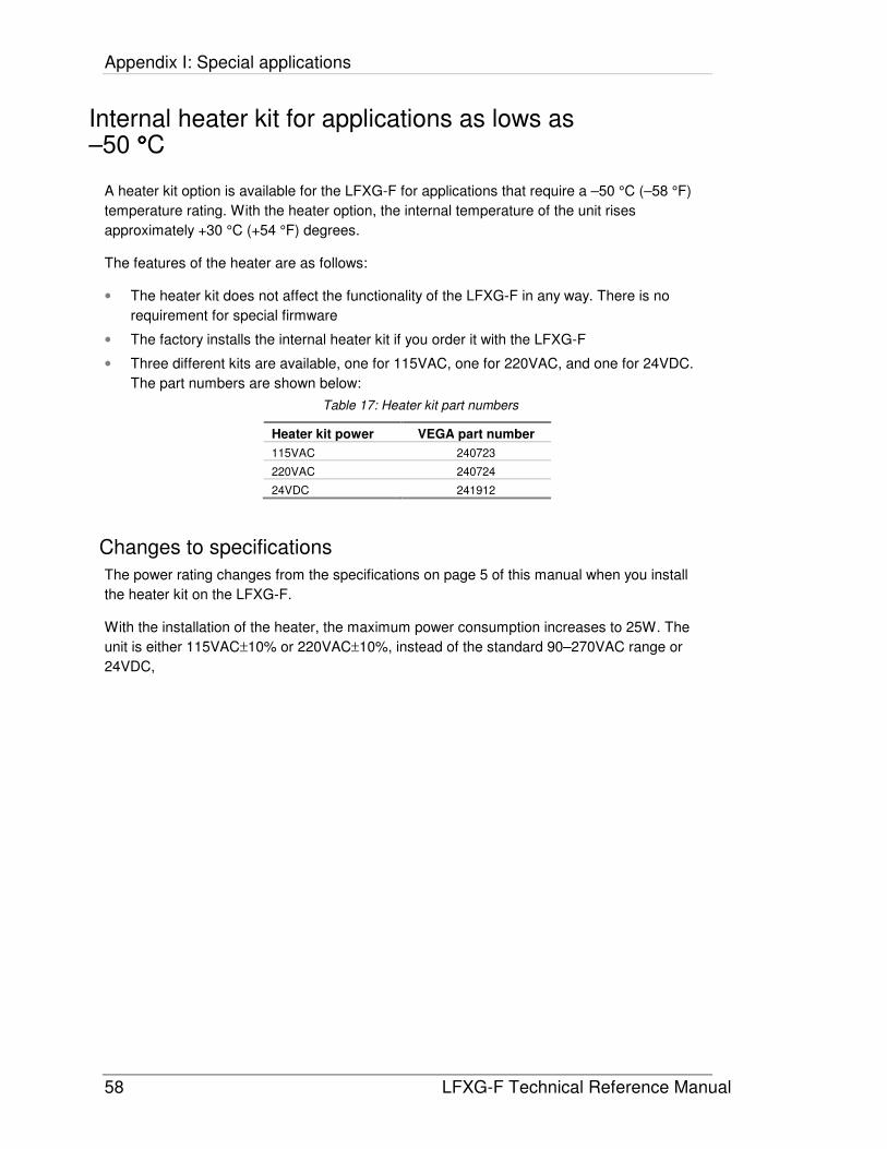
• Three different kits are available, one for 115VAC, one for 220VAC, and one for 24VDC.
The part numbers are shown below:
Table 17: Heater kit part numbers
Heater kit power VEGA part number
115VAC 240723
220VAC 240724
24VDC 241912
Changes to specifications
The power rating changes from the specifications on page 5 of this manual when you install
the heater kit on the LFXG-F.
With the installation of the heater, the maximum power consumption increases to 25W. The
unit is either 115VAC±10% or 220VAC±10%, instead of the standard 90–270VAC range or
24VDC,
LFXG-F Technical Reference Manual 59
Index
A
applications, 6
C
Cal Hi on Process, 29 Cal Lo on Process, 27 calibration
initial. See initial calibration, See initial calibration
process, 25 calibration curve, 26 Conduit, 19 CPU board
jumpers, 41 replacing, 45 test points, 39
Customer Order (C.O.) Number, 7 required for repairs, 47
D
drawings, 51
F
Field service. See VEGA Customer Service
G
ground screw, internal and external, 16
H
high/low level calibration, 31
I
initial calibration, 25, 26 new required, 35 not possible, 35
J
jumpers, 41, 52
L
low temperature application, 58
M
Max Reading, 26 Memory transfers, 24 Min Reading, 26
R
re-cal, 36 repairs
returning equipment to VEGA, 47
S
shutter check frequency, 43
source holder, 9 source holder lock, 21 source wipe
frequency, 43 spare parts, 43 specifications
FiberFlex, 5 heater kit changes, 58
storage, 3
T
test points, 39, 40 two-point calibration. See Initial calibration
V
vessel agitators effect, 13 VEGA Customer Service, 7
Field Service, 7 VEGA Field Service, 1, 47 VEGAt Parts and Repairs, 43
Notes

� � � � � � � � � � � � � �� � � � � � � � � � � � �� � � � � � � � � � � � � � � � ! �" � � � # � � � � $ � � � � � � � $ �% & # � � � � $ � � � � � � � $ $� ' � � � # � � � � � ( � � ) � � � �* * * + , - . / 0 / 1 - 2 3 4 / 5 + 4 6 1
7 8 9 9 : ; < = ; 8 8 > 7 > 8= ? @ A B C D D E C F G H I B J K D F E ? D L M K E M H E D K C BN O P Q R R S T U V W X Y Z [ \ W ] ^ V \ W V \ \ X _ V Z ` a V b Z c d R e f g gR h h Y _ X _ T S T \ _ Y W b \ W T U \ V \ i Y W b j T b k l T h V m T U n ZX j j h V W X _ V b \ Z j U X W _ V W X h o Y T Z X \ l b j T U X _ V \ i W b \ l V _ V b \ Yb k _ a T Y T \ Y b U Y X \ l j U b W T Y Y V \ i Y n Y _ T S Y W b U U T Y j b \ l_ b _ a T V \ k b U S X _ V b \ X m X V h X p h T X _ _ a T _ V S T b k j U V \ _ V \ i ]


![EECS 373 - University of Michiganweb.eecs.umich.edu/~prabal/teaching/eecs373-w15/slides/lec2-6up.pdf · EECS 373 Design of ... [ARM TRM] ARM DDI 0337E, “Cortex-M3 Technical Reference](https://static.fdocuments.in/doc/165x107/5af6d69f7f8b9a154c919139/eecs-373-university-of-prabalteachingeecs373-w15slideslec2-6uppdfeecs-373.jpg)